

Teeter Hang Ups ComforTrak Series, ComforTrak EP-560, ComforTrak EP-860, ComforTrak EP-960, ComforTrak EP-970 Assembly Instructions Manual

www.ActiveForever.com
ComforTrakTM Series
Assembly Instructions
EP-560, EP-860, EP-960 & EP-970 Models
*Inversion Table images may
vary slightly from your model.
The EP-560 is shown here.

BEFORE YOU BEGIN: Review all steps before beginning assembly and read all precautions before using the inversion table.
Carefully adhere to the Assembly Instructions and Owner’s Manual to help ensure safety and product integrity.
IMPORTANT SAFETY INSTRUCTIONS
READ ALL INSTRUCTIONS BEFORE USING THE INVERSION TABLE.
WARNING
!
WARNING - To reduce the risk of injury to persons:
• Read and understand all the instructions, view the instructional video, review all other accompanying documents, and inspect the
equipment before using the inversion table. It is your responsibility to familiarize yourself with the proper use of this equipment and the
inherent risks of inversion, such as falling on your head or neck, pinching, entrapment, or equipment failure. It is the responsibility of
the owner to ensure that all users of the product are fully informed about the proper use of the equipment and all safety precautions.
•
Close supervision is necessary when the inversion table is used near children, or by or near invalids or disabled persons.
• Use the inversion table only for its intended use as described in this manual. DO NOT use attachments not recommended by the
manufacturer.
• NEVER drop or insert any object into any opening.
• DO NOT use or store product outdoors.
• DO NOT use if you are over 6 ft 6 in (198 cm) or over 300 lbs. (136 kg). Structural failure could occur or head/neck may impact the
oor during inversion.
• DO NOT allow children to use this machine.
• Keep children, bystanders, and pets away from machine while in use.
• Keep body parts, hair, loose clothing and jewelry clear of all moving parts.
• The inversion table has no user serviceable parts.
• This product is intended for indoor home use only. DO NOT use in any commercial, rental or institutional setting.
FAILURE TO FOLLOW INSTRUCTIONS AND WARNINGS COULD RESULT IN SERIOUS INJURY OR DEATH.
SAVE THESE INSTRUCTIONS

BEFORE YOU BEGIN: Review all steps before beginning assembly and read all precautions before using the inversion table.
Carefully adhere to the Assembly Instructions and Owner’s Manual to help ensure safety and product integrity.
IMPORTANT SAFETY INSTRUCTIONS
READ ALL INSTRUCTIONS BEFORE USING THE INVERSION TABLE.
WARNING
!
• DO NOT use the equipment without a licensed physician’s approval and a review of the medical contraindications, as noted in the
Owner’s Manual.
• Failure to assemble and/or use the equipment as directed may void the manufacturer’s warranty on this product and could result in
injury or death.
• Choose a level surface for assembling and operating the table.
• Follow each step in sequence. DO NOT skip ahead.
• Make sure that all fasteners are secure.
• ALWAYS test and inspect the table. Make sure the table rotates smoothly to inverted position and back.
• ALWAYS replace defective components immediately and/or keep the equipment out of use until repair.
FAILURE TO FOLLOW INSTRUCTIONS AND WARNINGS COULD RESULT IN SERIOUS INJURY OR DEATH.
SAVE THESE INSTRUCTIONS
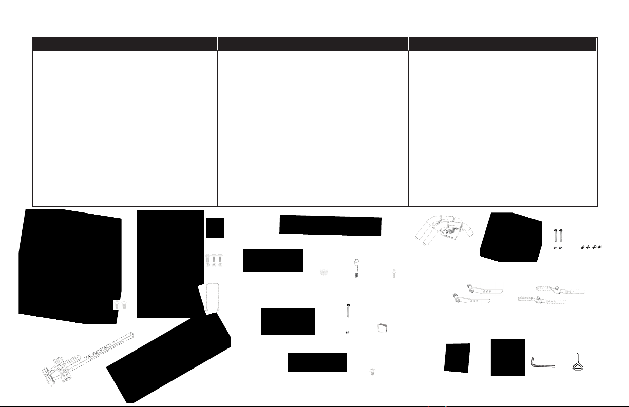
ITEMS FOR ASSEMBLY ITEM NUMBER
A-Frame
Angle T ether
EZ-AngleTM T ether (EP-860, EP-960, EP-970)
(EP-560 models)
Stability Feet (2) May come pre-assembled
Screws (2)
Table Bed
Upper Bed Portion
Lower Bed Portion & Frame
Head Pillow
Bolts & Nuts (3)
ComforTrak
TM
Bed Frame Extension
Main Shaft with EZ-Reach
(for EP-960 model only)
Main Shaft with Deluxe EZ-Reach
System
(for EP-970 model only)
TM
Ankle Lock System
TM
Ankle Lock
E6-1100
F5-1007
F5-1008
F7-1033
E1-1002
E6-1300A
E6-1300B
E6-1105
F1-1390
E6-1380
E6-1630
NX-1630B
Items for Assembly
ITEMS FOR ASSEMBLY
This column is ONLY for the Assembly of the
Main Shaft with T-Pin Ankle Lock System (E6-1600)
Main Shaft
(for EP-560 models, EP-860 only)
with T-Pin Ankle Lock System
Rear Ankle Bar
Rear Heel Cup (one pre-assembled, one separate)
Rubber Plug (1)
Bolt/Nut (1)
Screw (1)
Front Ankle Bar
Bolt (1)
Nut (1)
End Cap (1)
Ankle Comfort Dial Bar
Ankle Comfort Dials (2) (one pre-assembled, one separate)
Screw (1)
ITEM NUMBER
E6-1600
IA-1113
EP-1054
F5-1056
F5-1087
H1-1200
EP-1045B
F5-1089
H1-3007
F5-1048
IA-1119
IA-1118
IA-1123
ITEMS FOR ASSEMBLY
Handle Assembly
Strech Assist
Strech Max
Bolts & Nuts (2) (EP-860, EP-960, EP-970 ONLY)
Allen Head Screws (4)
TM
Handles (2) (EP-560 models only)
TM
Handles (2) (EP-860, EP-960, EP-970)
May come pre-assembled
Roller Hinge Assembly
3-Hole Roller Hinges (2)
Traction Handle 3-Hole Roller Hinges (2)
(EP-560 Sport, EP-960, EP-970)
(EP-560, EP-560 Ltd. EP-860)
Tools
10/13mm Wrenches (2)
Packaged with the Roller HInge Assembly
5mm Allen Wrench
Screwdriver
ITEM NUMBER
E6-1500
E6-1520
H1-1209
F5-0071
F5-1064
TR-1003
F5-1088
IA-1149
F5-1130
E6-1100
F5-1007
F5-1008
E6-1300A
F7-1033
E1-1002
E6-1630 NX-1630B
E6-1300B
E6-1105
F1-1390
E6-1380
IA-1113
EP-1054
EP-1045B
F5-1056
E6-1600
F5-1087 H1-1200
F5-1089
H1-3007
IA-1118
IA-1123IA-1119
F5-1048
EP-1105
F5-1064
H1-1209
TR-1003
F5-1088
F5-0071E6-1500 E6-1520
F5-1130IA-1149
Items are not shown to scale.


BEFORE BEGINNING
Before reading further, study the drawing below to familiarize yourself with
the important components of your new Teeter Hang Ups
Head Pillow
1
Bed Frame Extension
2
ComforTrak™ Table Bed
3
3-Hole Roller Hinges
4
Handles
5
Height-Selector Locking Pin
6
Spreader Arms
7
8
Angle Tether
9
Crossbar
10
A-Frame
11
Main Shaft
12
Ankle Lock System
13
Ankle Comfort Dial™
14
Stability Feet
What Model Do You Own?
Important: Please locate the model of your
Teeter inversion table before assembly.
The model can be found on A) the exterior of the box,
or B) the serial label located on the back of the table bed.
My Serial Number:
__________________
®
inversion table.
10
12
1
3
4
5
6
9
11
8
7
2
Don’t forget to register your
warranty
13
14
*Inversion Table images may
vary slightly from your model.
The EP-560 is shown here.

WARNING LABEL PLACEMENT
Important: Please review all labels and supporting materials before using your inversion table.
This drawing indicates the locations
of the warning labels found on your product.
If a label is missing, illegible or is removed,
contact Customer Service at the phone number or
website found at the bottom of this page to request a
complimentary replacement label.
Note: Image and labels below not shown at actual size.
If you have any questions, please contact our Customer Service Department at 1.800.847.0143
We hope you enjoy your new Teeter Hang Ups Inversion Table!

FIGURE 1
FIGURE 2
FIGURE 3
Right
1
Back
Left
Right
2
Step 1
Assemble the front Stability Feet (F7-1033) onto the A-Frame (E6-1100)
Feet may come pre-assembled.
• Lay the A-Frame on the floor with the Crossbar on the top side (Figure 1) to assemble
the front Stability Feet.
• Select the Stability Foot labeled Number 1 on the inside and place it on the RIGHT side of
the A-Frame. Insert two of the Screws (E1-1002), one through the side and one through the
bottom (Figure 2). Tighten using the Screwdriver (F5-1130) provided.
• Repeat with the Stability Foot labeled Number 2 on the LEFT side (Figure 2).
• Position the A-Frame on its feet and open it so the Spreader Arms are locked (Figure 3).
• Familiarize yourself with the Front, Back, Left and Right of the A-Frame. You may want to
refer back to this diagram for reference throughout the assembly process.
Left
1
Spreader Arms
2
Crossbar
Front

EP-560, EP-560 Sport & EP-560 Limited Models
FIGURE 4
Step 2
Depending on the model you have purchased, the items in this step will vary.
See “Which Model Do you Own?” (page 4) for more information.
FIGURE 4A
Assemble the Handles to the Table Bed (EP-1300)
Bolts/Nuts may come pre-assembled in the Handles. Simply unscrew to remove.
EP-560 models: Assemble the Stretch Assist Handles (E6-1500)
• Place each Handle (left / right) over the outside edge of the corresponding Hinge Plate.
The handles are stamped with an “L” for Left and an “R” for Right, this can be found on the
interior of the handle (Figure 4).
• Insert three Allen Head Bolts ((F5-0071) through the Hinge Plate into each Handle (Figure
4A). Tighten with the Allen Wrench provided, being careful not to overtighten.
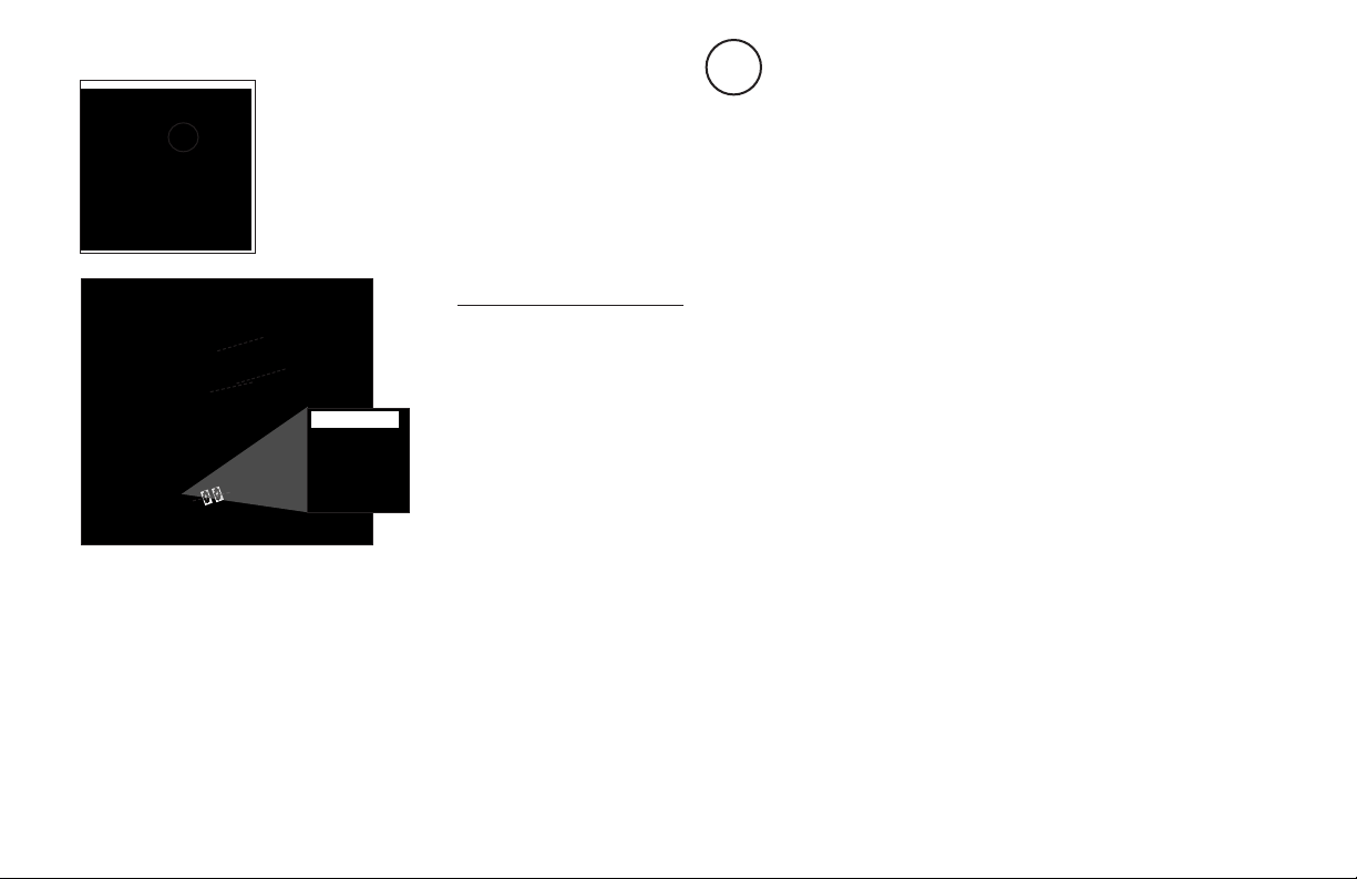
FIGURE 5
EP-860, EP-960, EP-970 Models
FIGURE 6
FIGURE 6A
Step 2
(continued)
Assemble the Handles to the Table Bed (EP-1300)
Bolts/Nuts may come pre-assembled in the Handles. Simply unscrew to remove.
EP-860, EP-960 & EP-970: Assemble the Stretch Max Handles (E6-1520)
• Assemble one side at a time. It does not matter which side (left / right) you start with.
• Using the 10/13mm Wrench (F5-1088), remove the Bolt, Nut and three Washers from where
the Spreader Arm meets the rear of the A-Frame (Figure 5). Discard the Bolt and Nut, but
keep one of the Washers.
• Place the corresponding Handle (left / right) over the outside edge of the Hinge Plate (refer
to Figure 6).
• Insert and loosely hand-tighten the three Allen Head Bolts ((F5-0071) through the Hinge
Plate into the handle (Figure 6).
• Position the lower part of the Handle between the Spreader Arm and the A-Frame leg.
Thread one Washer on the Bolt and insert from the inside of the A-Frame. Make sure the
Bolt goes through the A-Frame leg, Handle and Spreader Arm. Thread one Washer on the
end and secure with the Nut (Figure 6). Refer to Figure 6A for how the finished assembly of
this should look.
• Fully tighten all Bolts, using the Allen Wrench provided, being careful not to overtighten.
• Repeat on the other side.

FIGURE 7
FIGURE 7A
FIGURE 7B
Step 3
Depending on the model you have purchased, the items in this step will vary.
See “Which Model Do you Own?” (page 4) for more information.
EP-560 models & EP-860: Complete this step.
EP-560 Sport: Complete this step to use the standard Ankle Lock System. To use with the
EZ-Up Gravity Boots refer to either the ComforTrak DVD or the insert that can be found with
the Conversio Bar.
EP-960 & EP-970: Skip this step and proceed directly to Step 4.
Assemble the T-Pin Ankle Lock System onto the Main Shaft (E6-1600)
Install the Ankle Comfort Dial
• Slide the Ankle Comfort Dial Bar (IA-1119) with pre-assembled Ankle Comfort Dial into the
hole at the front base of the Main Shaft (Figure 7).
• The Ankle Comfort Dial is designed with a High and Low setting. Position the pre-assembled
Dial in the Low Setting (screw holes facing up) for ease of assembly. Slide the separate
Ankle Comfort Dial (IA-1118) onto the Ankle Comfort Dial Bar.
• Insert the Screw (IA-1123) (Figure 7A) and tighten with the Screwdriver (F5-1130) provided.
See Figure 7B for detailed view of Screw (IA-1123).
NOTE: Refer to the Owner’s Manual for a complete description of the Ankle Comfort Dial
settings.

FIGURE 8
FIGURE 8A
FIGURE 9
FIGURE 9A
1 Ridge
2 Ridges
Step 3
(continued)
Install the Rear Ankle Bar Assembly
• With the two ridges of the pre-assembled Heel Cup on the bottom, insert the Rear Ankle Bar
(IA-1113) into the large hole at the back of the Main Shaft (Figure 8).
• Insert the Bolt (F5-1087) from the rear of the Main Shaft to secure the Rear Ankle Bar
(Figure 8), and fasten with the Washer and Nut using the wrenches provided.
• Slide the separate Heel Cup (EP-1054), with the two ridges on the bottom, onto the open
end of the Rear Ankle Bar (Figure 8A).
TIP: To assist with assembly, repeatedly rotate the Heel Cup while pushing it onto the Rear
Ankle Bar.
• Align the pre-drilled holes of the Rubber Plug with the holes in the Rear Ankle Bar. Insert the
Rubber Plug (F5-1056) into the open end of the Rear Ankle Bar (Figure 9).
TIP: You may want to use a rubber mallet to assist with assembly.
• Secure the Rubber Plug with the Screw (H1-1200) using the Screwdriver (F5-1130) provided
(Figure 9A). If the Screw does not tighten easily, you may need to reposition the alignment of
the Rubber Plug.
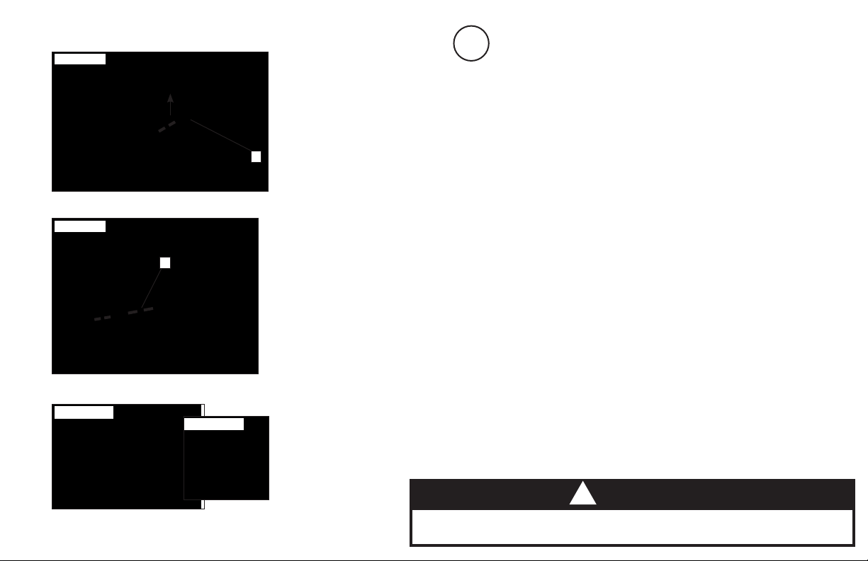
FIGURE 10
Front Ankle Bar Housing
1
FIGURE 11
1
Retainer Spring & Cable Loop
Step 3
Install the Front Ankle Bar Assembly
• With hole settings facing up, insert the Front Ankle Bar (EP-1045B) into the Front Ankle Bar
Housing (Figure 10). Pull up on the T-Pin Lock to allow the Front Ankle Bar to insert all the
way into the housing. Release the T-Pin to engage in the hole setting closest to the Front
Ankle Cups.
1
• From the reverse side, pull on the zip-tie to stretch the Retainer Spring and Cable Loop so
that they align with the holes in the back of the Front Ankle Bar Housing (Figure 11).
• Insert the Bolt (F5-1089) starting through the outer side of the housing in the following order:
hole, Retainer Spring and Cable Loop, hole (Figure 11).
• Tighten the Nut (H1-3007) using the 13mm Open Wrench (F5-1088) provided.
1
• Cut the long portion of the zip-tie with scissors (Figure 11A) so that it doesn’t interfere with
the function of the Retainer Spring. Cover the open end with the End Cap (F5-1048)
(Figure 11B).
(continued)
FIGURE 11A
FIGURE 11B
!
WARNING
Failure to assemble the T-Pin Ankle Lock System properly could
result in serious injury or death!

FIGURE 12
Center Bolt (1)
FIGURE 13
Upper Bolts/Nuts (2)
1
Bed Frame Extension - Loop
1
FIGURE 14
Step 4
Assemble the Table Bed (E6-1300) and Bed Frame Extension (E6-1380)
NOTE: This assembly will be referred to as Table Bed (E6-1300) for the remainder of the
Assembly Instructions.
• Locate the following items to assemble the Table Bed:
ComforTrak™ Bed - Upper Portion (E6-1300A) ComforTrak™ Bed Frame (E6-1300)
Bed Frame Extension (E6-1380) Bolts & Nuts (F1-1390)
5mm Allen Wrench (IA-1149) 10/13mm Wrench (F5-1088)
• Lay the ComforTrak™ Bed - Upper Portion (E6-1300A) face down on the floor.
• Place the ComforTrak™ Bed Frame (E6-1300) face down on top of the Upper Portion
and align the bolt holes.
• Reaching underneath, insert a Bolt in the center hole and hand-tighten with a Nut
(Figure 12).
• Reaching underneath, insert one of the remaining Bolts through one of the holes in the
Upper Portion and hold in place. Slide one of the Bed Frame Extension loops over the
Bolt and hand-tighten with a Nut (Figure 13).
• Repeat with remaining side (Figure 14).
• To fully tighten all three nuts to the bolts, insert the 5mm Allen Wrench (IA-1149) into
the Bolt heads and tighten the Nuts using the 10/13mm Wrench (F5-1088).
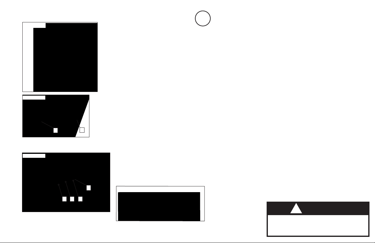
FIGURE 15
FIGURE 16
Pivot Pin
1
Cam Lock
2
FIGURE 17
Step 5
Depending on the model you have purchased, the items in this step will vary.
See “Which Model Do you Own?” (page 4) for more information.
Assemble the Roller Hinges to the Table Bed (EP-1300)
EP-560, EP-560 Ltd. & EP-860: Use 3-Hole Roller Hinges (F5-1064)
EP-560 Sport, EP-950 & EP-970: Use 3-Hole Roller Hinges with Traction Handles (TR-
1003)
• For ease-of-assembly, rest the Table Bed against the Crossbar (Figure 15).
• Open the Cam Locks on each side of the Table Bed (Figure 16).
• With the Pivot Pins facing outward, insert the Roller Hinges into the brackets on each side
of the Table Bed Assembly. The Roller Hinges must slide between the Cam Locks and the
Brackets (Figure 16).
1
2
• Engage one of the holes in the Roller Hinge over the Bracket Pin. Make sure the Roller
Hinges are in the same hole setting on both sides. Figure 17 shows the Roller Hinges
engaged correctly, with the Bracket Pin engaged in Setting C.
• Push down on the Cam Locks (Figure 18) to secure the Roller Hinges.
NOTE: Refer to the Owner’s Manual for an explanation of the hole settings.
If you are unsure, use Setting C to start.
Bracket Pin
1
1
FIGURE 18
CBA
Unlocked
Locked
!
WARNING
NEVER disassemble the Roller Hinge.

FIGURE 19
FIGURE 19A
Roller Hinge Pivot Pin
1
Self-Locking Hook
2
FIGURE 20
Step 6
Attach the Table Bed (E6-1300) to the A-Frame (E6-1100)
• Pick up the Table Bed, holding each side near the Roller Hinges, and stand in front of the
A-Frame where the Crossbar is located (refer to Figure 3 to determine A-Frame Front).
• Lower each Roller Hinge Pivot Pin into the A-Frame hinge plates, one side at a time
(Figures 19 and 19A). With pressure, the Self-Locking Hooks will open to allow the Pivot Pin
into the slot, then automatically close over the Pivot Pin.
NOTE: You may need to push outward on the A-Frame in order for the 2nd Pivot Pin
1
2
1
2
to lock in place.
• Make sure that each Pivot Pin is seated at the base of the slot of the Hinge Plate (Figure 20),
that the Self-Locking Hooks have closed over both Pivot Pins, and that the Table
Bed rotates smoothly.
Self-Locking Hook
1
Roller Hinge
2
!
WARNING
Failure of the Self-Locking Hooks to close over both Roller Hinge
Pivot Pins is an indication of improper assembly and if not corrected
could result in serious injury or death!

FIGURE 21
Step 7
Depending on the model you have purchased, the items in this step will vary.
See “Which Model Do you Own?” (page 4) for more information.
1
2
Main Shaft
1
2
Main Shaft Housing
Height-Selector Locking Pin
3
FIGURE 22
Proper Resting Position
1
Crossbar
2
FRONT
1
3
Insert the Main Shaft into the Table Bed
EP-560 and EP-860 models will use the Main Shaft with T-Pin Ankle Lock System (E6-1600)
EP-960 model will use the EZ-Reach Ratchet Ankle Lock System (E6-1630)
EP-970 model will use the Deluxe EZ-Reach Ratchet Ankle Lock System (NX-1630B)
• With the Height Adjustment Settings on the Main Shaft facing up, slide the end of the
Main Shaft into the Main Shaft Housing (Figure 21) on the Table Bed.
• Pull out the Height-Selector Locking Pin to allow the Main Shaft to slide in further and release
in the desired height setting. Refer to the Owner’s Manual for more information on selecting
your height setting.
• The Main Shaft MUST REST against the Crossbar of the A-Frame (Figure 22).
2
NOTE: The Crossbar prevents the Table Bed from rotating forward when the user steps
on the Ankle Comfort Dial. If the Main Shaft does not rest on the Crossbar as shown in
Figure 23, then the Table Bed has been assembled backwards onto the A-Frame.
This MUST BE CORRECTED before use.

!
WARNING
If your Teeter Hang Ups Inversion Table looks like either of these images, your table has been misassembled and is unfit for use.
Image A
Go back to Step 5 for instruction
Demonstrates that the Roller Hinges have been assembled
upside down into the Table Bed and must be corrected.
If you have any questions, please contact our Customer Service Department at 1.800.847.0143
Improper assembly could result in serious injury or death!
Image B
Go back to Step 6 for instruction.
Demonstrates that the Table Bed has been assembled
into the A-Frame backwards and must be corrected.
We hope you enjoy your new Teeter Hang Ups Inversion Table!

FIGURE 23
Step 8
Depending on the model you have purchased, the items in this step will vary.
See “Which Model Do you Own?” (page 4) for more information.
Assemble the Tether to the Table Bed (EP-1300)
EP-560 & EP-560 Sport: use the Angle Tether (F5-1007)
EP-860, EP-960 & EP-970: use the EZ-Angle Tether (F5-1008)
• The Tether will come pre-assembled to the A-Frame.
• Unfold the adjustable Tether and clip it to the U-Bar on the underside of the Table Bed
(Figure 23).
• The EZ-Angle Tether has color coded angles to assist in varied angles of inversion for
your experience level:
20° / Gentle Inversion
Green stripe must show in the center of the sliding buckle.
40°/ Moderate Inversion
Orange stripe must show in the center of the sliding buckle.
60° / Intermediate Inversion
Red stripe must show in the center of the sliding buckle.
This is the angle when full decompression is realized.
90° / Advanced Inversion
Remove the tether strap clip from U-Bar to enable rotation to full inversion.

FIGURE 24
FIGURE 25
Step 9
Attach the Head Pillow (EP-1105)
• Attach the Head Pillow by securing the Velcro Straps through the holes in the Table Bed
(Figure 24). The position of the pillow can be adjusted depending on the user.
Attach the Owner’s Maunal
The Owner’s Manual contains important information on how to use your Teeter Hang Ups, including how
to personalize the user settings, properly secure and release the Ankle Lock System, and test and adjust
the rotation control.
• If not already attached, thread the provided metal chain, provided, through the pre-punched
hole in the upper corner of the Owner’s Manual.
• Secure the chain to the A-Frame through the designated hole in the HInge Plate (Figure 25).
Allow the Owner’s Manual to hang freely on the outside of the A-Frame Spread Arms so it
doesn’t interfere with the rotation of the Table Bed.
IMPORTANT: Do not remove the Owner’s Manual. It should remain permanently attached
to the A-Frame of your inversion table to serve as a reference for proper adjustment and
use of the equipment.
Before Use
• Test the Inversion Table by hand for smooth and steady rotation (Figure 25) and that all
fasteners are secure.
• Please complete the warranty registration online
!
WARNING
Read the Owner’s Manual thoroughly before using your Teeter Hang Ups
Inversion Table. Improper settings could result in serious injury or death!

FIGURE 26
FIGURE 27
FIGURE 28
Adjusting the Roller Hinge Setting
Adjustments: Changing the Roller Hinge Setting
To adjust the Roller Hinge setting, you’ll need to fully remove the Table Bed from the
A-Frame.
• Remove the Angle Tether from the U-Bar located on the underside of the Table Bed.
• Pull the Height-Selector Locking Pin and slide the Main Shaft in all the way to the last
hole setting.
• Release and engage the Pin in the storage setting.
• Rotate the Table Bed opposite from use until it has turned 180° and rests against
the Crossbar of the A-Frame (Figure 26).
• With palms up, reach under and around each Roller Hinge, using your thumbs to release
the Self-Locking Hooks over the Pivot Pin (Figure 27).
• Lift both sides of the Table Bed out of the A-Frame at the same time. TIP: Rest the head
of the Table Bed on the floor for quick adjustment. Unlock the Cam Locks for each Roller
Hinge. Change the Roller Hinges to the desired setting (A, B or C).
NOTE: Refer to the Owner’s Manual for more information on finding your Roller Hinge
Setting.
• Re-lock the Cam Locks (Figure 28). Replace the Table Bed onto the A-Frame by lowering
the Roller Hinges into the hinge plates of the A-Frame.
• Rotate the Table Bed back to the use position and re-adjust the Main Shaft height settings
for use.
CBA

FIGURE 29
Maintenance/ Storage
Maintenance
• To clean the Inversion Table, wipe down with a damp cloth. Do not use abrasive
cleaners or solvents.
Storage
• Remove the Angle Tether from the U-Bar located on the underside of the Table Bed.
• Pull the Height-Selector Locking Pin and slide the Main Shaft in all the way to the
last hole setting.
• Release and engage the Pin in the storage setting.
• Rotate the Table Bed opposite from use until it has turned 180° and rests against
the Crossbar of the A-Frame.
• Pull up on the Spreader Arms to fold the A-Frame (Figure 29), leaving the A-Frame
legs open to a width of 12” for stability.
NOTE: This operation may pinch fingers if not done slowly and carefully.
!
WARNING
Tipping Hazard: For upright storage, leave A-frame open wide
enough to remain stable, or secure to the wall to prevent tipping.
In households with small children, the inversion table should be stored
at on the oor, not upright.
 Loading...