

Page 1
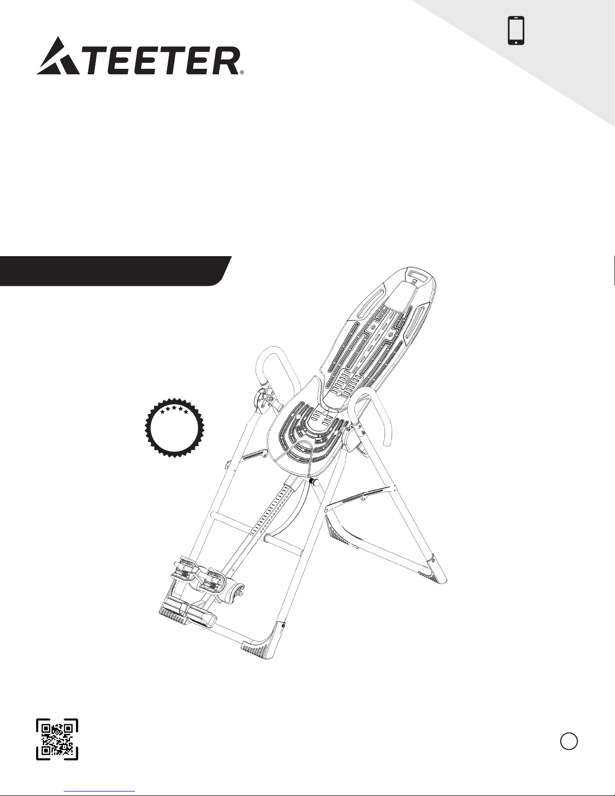
NXT-S™
Inversion Table
Assembly Instructions
NEW!
Follow along with
your smartphone
to make assembly
even easier!
5
W
FULL
YEAR
A
R
A
R
Y
T
N
* Specifications may vary from this image and
are subject to change without notice.
To download and print Teeter’s NXT-S instructions, visit the product support page at teeter.com.
Pour télécharger et imprimer le manuel du propriétaire NXT-S, visitez la page d’assistance des produits au teeter.com
EN
Page 2

Congratulations on your purchase of a Teeter NXT-S Inversion Table! This product has been carefully engineered to provide you with
precision rotation control and security to ensure the most comfortable and effective inversion experience.
In order to utilize this product to its fullest extent, it is critical that you follow the assembly instructions, read and fully understand the
Owner’s Manual attached to the equipment, and review the Getting Started DVD prior to using your new Teeter Inversion Table.
Follow the assembly steps with your smartphone! With a QR code reader app, scan the barcodes next to each assembly step
to watch the corresponding video to guide you through the instructions.
To register your product warranty, go to teeter.com/Support/Warranty-Registration
If you have any questions concerning assembly or if any parts are missing, DO NOT RETURN THE ITEM TO THE STORE
OR CONTACT THE RETAILER. Our dedicated customer service experts can help! Contact Teeter Customer Service
at 800.847.0143, or via online forms or Live Chat at teeter.com.
Assembly Instructions
Important Safety Instructions ........................1
Items for Assembly .................................. 2
Understanding Your Inversion Table ..................3
Safety Warning Labels & Product Specifications ..... 4
Before Beginning Assembly ......................... 5
Assembly Steps.................................. 6 – 13
Misassembly Check..................................14
Before Inverting .....................................15
Warranty Terms & Registration.......................16
Owner’s Manual (attached to the equipment)
Important Safety Instructions ........................1
User Settings ........................................ 2
Prepare to Invert.................................. 3 – 4
Inverting ..........................................4 – 5
Storage & Maintenance ..............................5
Get the Most out of Your Teeter .....................6
Page 3

BEFORE YOU BEGIN: Review all steps before beginning assembly and read all precautions before using the inversion table.
Carefully adhere to the Assembly Instructions and Owner’s Manual to help ensure safety and product integrity.
READ ALL INSTRUCTIONS BEFORE USING THE INVERSION TABLE
IMPORTANT SAFETY INSTRUCTIONS
!
WARNING
FAILURE TO FOLLOW INSTRUCTIONS AND WARNINGS COULD RESULT IN SERIOUS INJURY OR DEATH.
To reduce the risk of injury:
• Read and understand all the instructions, review all other accompanying documents, and inspect the equipment before using the
inversion table. It is your responsibility to familiarize yourself with the proper use of this equipment and the inherent risks of inversion
if these instructions are not followed, such as falling on your head or neck, pinching, entrapment, equipment failure, or aggravating a
pre-existing medical condition. It is the responsibility of the owner to ensure that all users of the product are fully informed about the
proper use of the equipment and all safety precautions.
• DO NOT use the equipment without a licensed physician’s approval. Carefully review the following list of medical contraindications for
inversion with your licensed physician (this is not an exhaustive list, it is intended only for reference):
• Middle ear infection
• Extreme obesity
• Pregnancy
• Hiatal or ventral hernia
• Eye conditions like glaucoma,
retinal detachment or
conjunctivitis
• Chronic sinusitis
• High blood pressure or
hypertension
• ALWAYS be certain the Ankle Lock System is properly adjusted and fully engaged, and that your ankles are secure before using
the equipment. HEAR, FEEL, SEE and TEST that the Ankle Lock System is snug, close-fitting and secure EVERY TIME you use
the equipment.
• ALWAYS wear securely tied lace-up shoes with a flat sole, such as a normal tennis-style shoe.
• DO NOT wear any footwear that could interfere with securing the Ankle Lock System, such as shoes with thick soles, boots, high-tops
or any shoe that extends above the anklebone.
• DO NOT use the inversion table until it is adjusted properly for your height and body weight. Improper settings can cause rapid
inversion or make returning upright difficult. New users, and users who are physically or mentally compromised, will require the
assistance of a spotter. Make sure the equipment is set to your unique user settings prior to each use.
• DO NOT sit up or raise head to return upright. Instead, bend knees and slide your body to the foot-end of the inversion table to change
weight distribution. If locked out in full inversion, follow the instructions for releasing from the locked position before returning upright.
• DO NOT continue using the equipment if you feel pain or become light-headed or dizzy while inverting. Immediately return to the
upright position for recovery and eventual dismount.
• DO NOT use if you are over 6 ft 6 in (198 cm) or over 300 lbs. (136 kg). Structural failure could occur or head/neck may impact the floor
during inversion.
• DO NOT allow children to use this machine. Keep children, bystanders, and pets away from machine while in use. The inversion table
is not intended for use by persons with reduced physical, sensory or mental capabilities, unless they are given supervision and
instruction concerning use of the machine by a person responsible for their safety.
• DO NOT store the inversion table upright if children are present. Fold and lay the table on the floor. DO NOT store outdoors.
• DO NOT use aggressive movements, or use weights, elastic bands, any other exercise or stretching device or non-Teeter
while on the inversion table. Use the inversion table only for its intended use as described in this manual.
• DO NOT drop or insert any object into any opening. Keep body parts, hair, loose clothing and jewelry clear of all moving parts.
• DO NOT use in any commercial, rental or institutional setting. This product is intended for indoor, home-use only.
• DO NOT operate equipment while under the influence of drugs, alcohol, or medication that may cause drowsiness or disorientation.
• ALWAYS inspect the equipment prior to use. Make sure all fasteners are secure.
• ALWAYS replace defective components immediately and/or keep the equipment out of use until repair.
• ALWAYS position equipment on a level surface and away from water or ledges that could lead to accidental immersion or falls.
• Refer to additional warning notices posted on the equipment. If a product label or Owner’s Manual should become lost, damaged or
illegible, contact Customer Service for replacement.
• Heart or circulatory disorders
• Use of anticoagulants
(including high doses of
aspirin)
• Weakness, frailty, or mobility
issues
• Dizziness, trouble with
coordination or head-down
disorientation
• Vertigo, motion sickness or
inner ear disorders
• Brain injury or recent head
trauma
• Recent stroke or transient
ischemic attack
• Spinal injury or conditions
impacting the spinal cord
• Cerebral sclerosis
• Medical conditions associated
with the weight-bearing joints
• Acutely swollen joints
• Bone weakness (osteoporosis)
• Recent or unhealed fractures
• Medullary pins or surgically
implanted orthopedic supports
• Any other medical condition
that may be made more
severe by an elevation of blood
pressure, intracranial pressure
or the mechanical stress of the
inverted position
®
attachments
SAVE THESE INSTRUCTIONS
1
Page 4
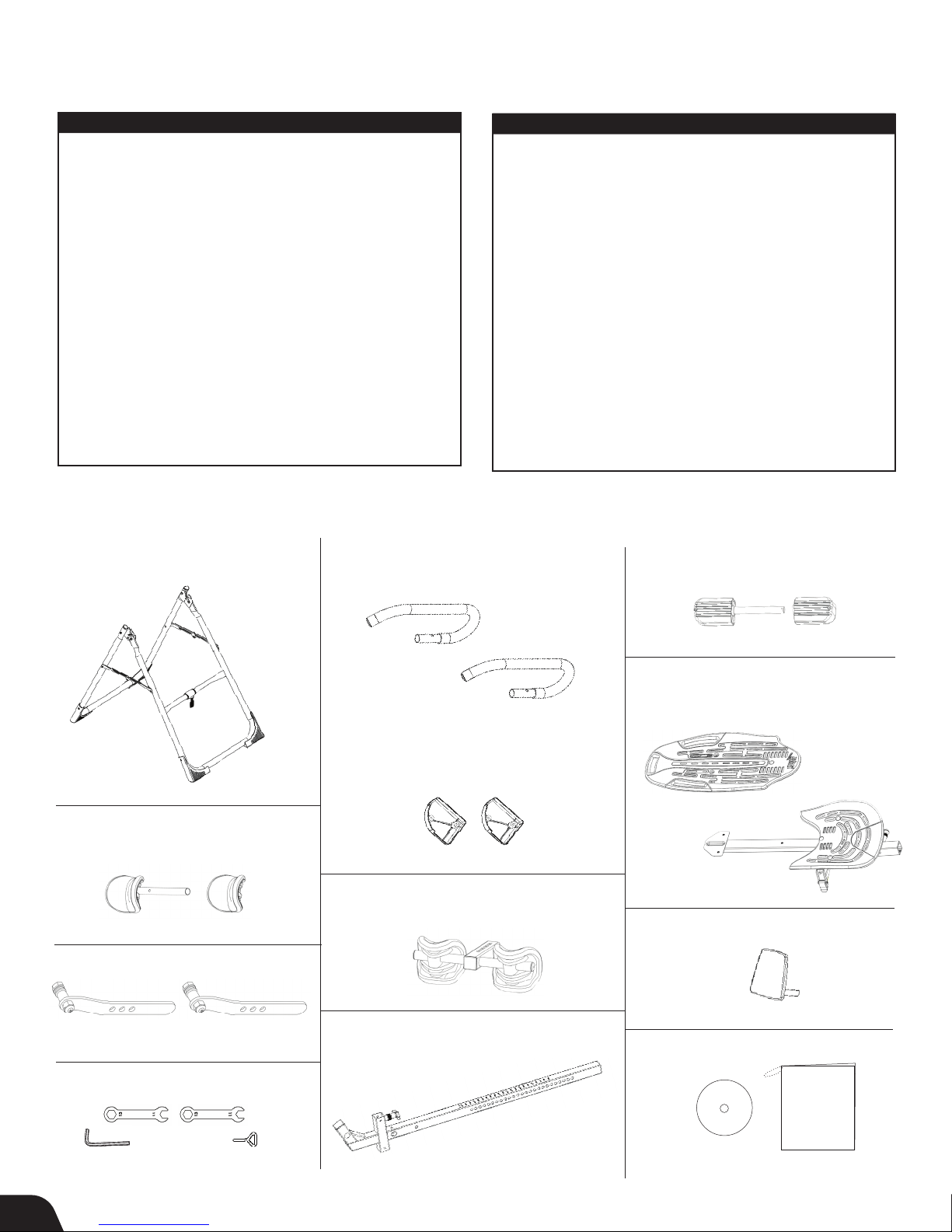
Items for Assembly
Items not shown to scale. Hardware drawings located on the insert inside each Hardware Kit.
ITEM NO. ITEM NAME
A-Frame Base Assembly
NX1105 A-Frame
F51007 Angle Tether
pre-assembled to A-Frame
Handle & Hinge Cover Assembly
NX1550 Support Handles (2)
HK1009 Handle Assembly Hardware Kit
F11250 Hinge Covers (2)
HK1002 Hinge Cover Assembly Hardware Kit
Ankle Comfort Dial Assembly
IA1119 Ankle Comfort Dial
HK1005 Ankle Comfort Dial Assembly Hardware Kit
Rear Ankle Bar Assembly
IA1113 Rear Ankle Bar
HK1003 Rear Ankle Bar Assembly Hardware Kit
Front Ankle Bar Assembly
EP1045 Front Ankle Bar
HK1004 Front Ankle Bar Assembly Hardware Kit
with pre-assembled Angle Tether
Base Assembly
Support Handle Assembly
use Support Handle Assembly
Hardware Kit (HK1009)
ITEM NO. ITEM NAME
Table Bed Assembly
E61301A Upper Portion
E61300B Lower Portion
HK1006 Table Bed Assembly Hardware Kit
Roller Hinge Assembly
F51064 3-Hole Roller Hinges
Main Shaft
E61600 with T-Pin Ankle Lock System
Optional Accessories
E61105 Head Pillow
Tools Provided for Assembly
F51088 10/13mm Open-Ended Wrenches (2)
IA1149 5mm Allen Wrench (1)
F51130 Screwdriver (1)
Product Support
NX1730 Getting Started DVD
NX1750 Owner’s Manual
(attached to A-Frame)
Ankle Comfort Dial Assembly
use Ankle Comfort Dial Assembly
Hardware Kit (HK1005)
NX1105
F51007
Rear Ankle Bar Assembly
use Rear Ankle Bar Assembly
Hardware Kit (HK1003)
IA1113
Roller Hinge Assembly
F51064
NX1550
Hinge Cover Assembly
use Hinge Cover Assembly
Hardware Kit (HK1002)
F11250
Front Ankle Bar Assembly
use Front Ankle Bar Assembly
Hardware Kit (HK1004)
EP1045
Main Shaft
with T-Pin Ankle Lock System
IA1119 IA1118
ComforTrak Table Bed Assembly
use Table Bed Assembly
Hardware Kit (HK1006)
E61301A
E61300B
Optional Accessories
E61105
Product Support
Tools Provided for Assembly
F51088
IA1149 F51130
2
E61600
NX1730
NX1750
Page 5
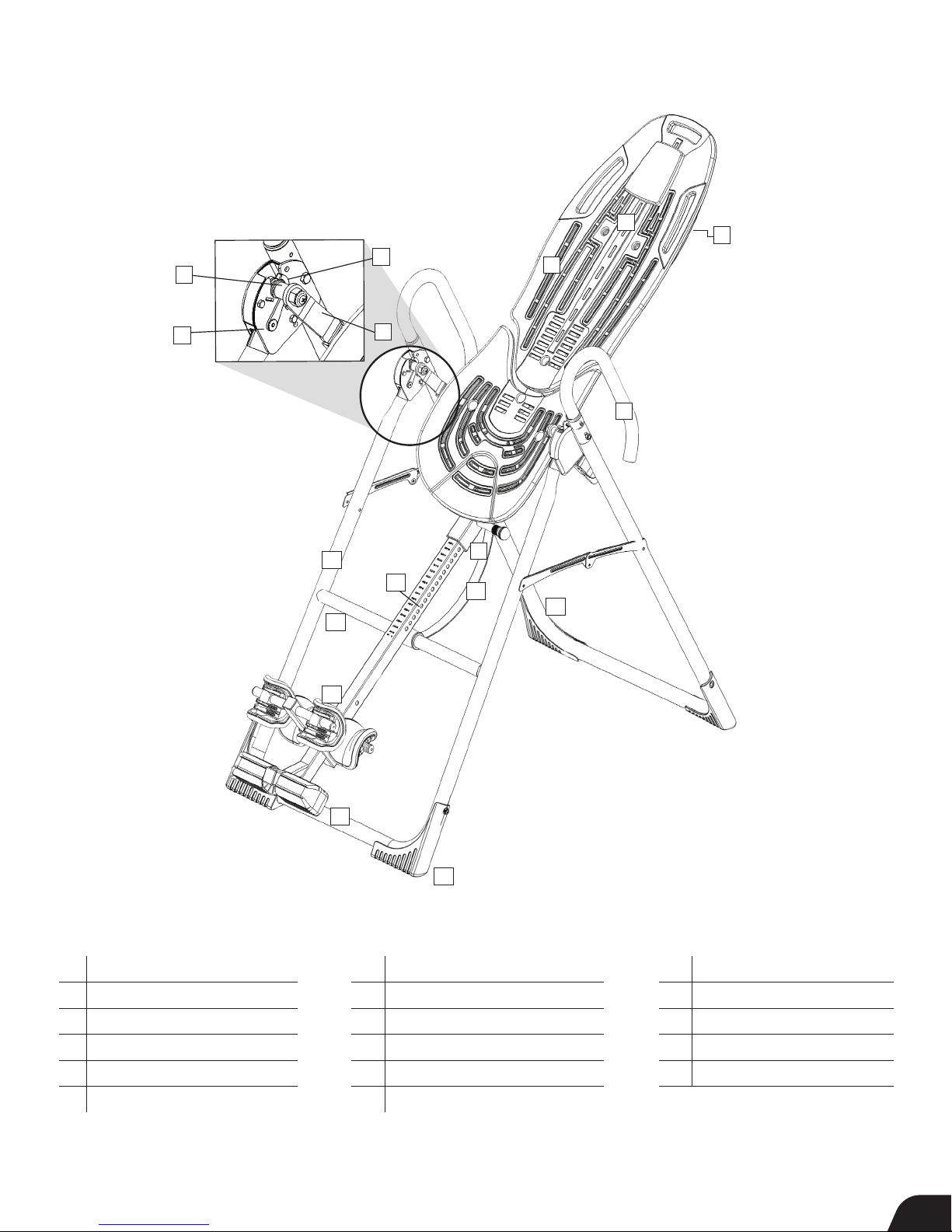
Understanding Your Inversion Table
Before reading further, study the drawing below to familiarize yourself with the
important components of your Teeter Inversion Table.
1
6
4
5
13
12
7
9
14
11
3
8
10
Located on
2
back of table
bed.
15
16
Identifying Parts and Components
1 Head Pillow
2 Bed Frame Extension
3 Table Bed
4 Pivot Pins
5 Hinge Plates
6 Self-Locking Hooks
7 3-Hole Roller Hinges
8 Support Handles
9 Height-Selector Locking Pin
10 Spreader Arms
11 Angle Tether
12 Crossbar
17
13 A-Frame
14 Main Shaft
15 Ankle Lock System
16 Ankle Comfort Dial
17 Non-Skid Stability Feet
™
3
Page 6
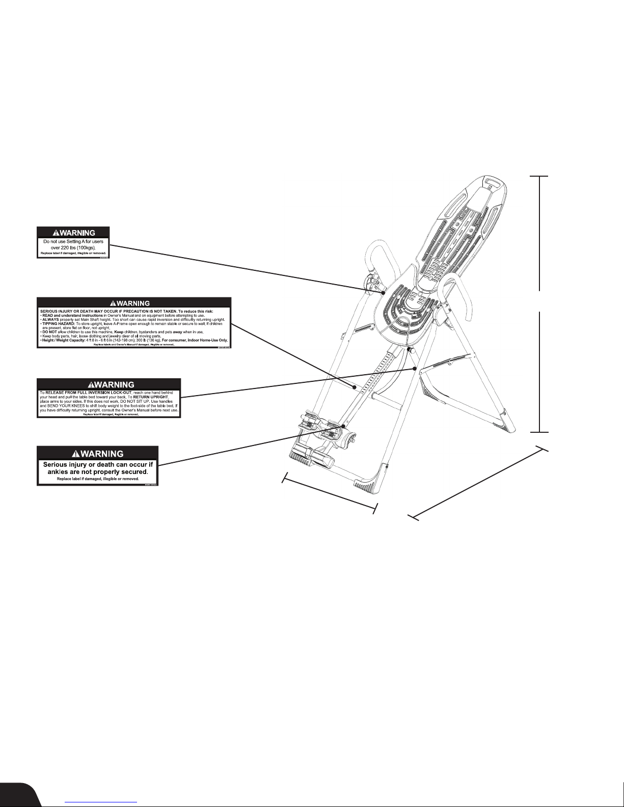
Safety Warning Labels & Product Specifications
Important: Please review all labels and supporting materials before using your inversion table.
This drawing indicates the locations of the warning labels found on your product. If a label is missing, illegible or is removed,
contact Teeter Customer Service to request a complimentary replacement label.
Note: Image and labels below not shown at actual size.
57 in (144.8 cm)
28.8 in (73 cm)
Assembled Non-Use Dimensions: 60.0 (L) x 28.8 (W) x 57.0 in (H) (152.4 x 73.0 x 144.8 cm)
Maximum In-Use Dimensions: 84.0 (L) x 28.8 (W) x 86.0 in (H) (213.4 x 73.0 x 218.4 cm)
Storage Dimensions: 22.0 (L) x 28.0 (W) x 66.0 in (H) (55.9 x 71.1 x 167.6 cm)
Weight
(approx.): 69.4 lbs (31.5 kg)
60 in (152.4 cm)
4
Page 7

Before Beginning Assembly
Unpack and Prepare Your Workspace
• If possible, set up the product at or near the space in which you intend to use it to avoid moving it later.
• Unpack all parts and support materials. Follow the unpacking instructions included in the box. Set aside packing materials
and clear your work area.
• Locate the Hardware Kits, packaged with the manuals. They are labeled to correspond with the assembly process.
• The Getting Started DVD provides step-by-step instruction on how to assemble your product. You may find it helpful to follow along
with the DVD by watching it on either your TV or computer. The DVD is divided into the following sections:
• Assembly - Follow step-by-step instruction on how to assemble your inversion table.
• User Settings - Personalize your inversion experience by adjusting four customizable settings.
• Use Instructions - Learn how to test your balance and rotation control, and how to properly invert and return upright.
• Advanced Stretching & Exercises - Use your Teeter for rotational stretches, sit ups, squats and more!
• BONUS Healthy Back Routines*
Dr. Shawn leads you through 5 original Healthy Back Routines, including one designed specifically for
use with your inversion table!
*Not available in French or Spanish.
Follow the Assembly Steps with Your Smartphone!
With a QR code reader app, scan the barcodes next to each assembly step to watch the corresponding
video to guide you through the instructions.
5
Page 8
STEP 1
REV.
DESCRIPTION
D
E
F
G
H
1
2
3
4
5
6
7
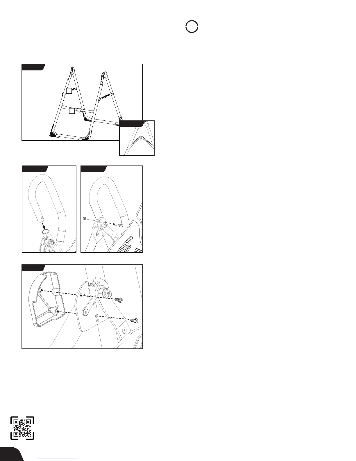
Assemble A-Frame Base & Support Handles
FIGURE 1
RIGHT
1
2
FRONT
1 - Spreader Arms 2 - Crossbar
FIGURE 2
FIGURE 2a
REAR
LEFT
FIGURE 1a
UNLOCKED
• On a level surface, position the A-Frame so that it is standing upright
and the Stability Feet are on the ground.
• Gently push down on the Spreader Arms to ensure they are fully open
and in the “locked” position (Figure 1).
• Look for temporary circular assembly assistance labels on the
A-Frame. RIGHT, LEFT, FRONT, and REAR indicate your position while
using the equipment, not facing it. These labels can be removed easily
upon completion of assembly.
Assemble Support Handles
• Locate the Handle Assembly Hardware Kit (HK1009)
• Insert the handles into the A-Frame (Figure 2), so that the long part
of the handles are parallel with the rear legs of the A-Frame.
• Insert the Bolts from the inside through the Hinge Plates and
Handles. Hand tighten with the nuts on the outside of the A-Frame
(Figure 2a).
• Tighten with the wrenches provided.
FIGURE 3
Assemble Hinge Covers to Hinge Plates
• Locate the Hinge Cover Assembly Hardware Kit (HK1002).
• Select the corresponding Hinge Covers for the left and right sides of
the A-Frame by aligning each with the shape of the Hinge Plate
(Figure 3).
• Secure with (2) Allen Head Bolts for each side using the 5mm
Allen Wrench provided. Be careful not to overtighten.
6
Page 9
STEP
2
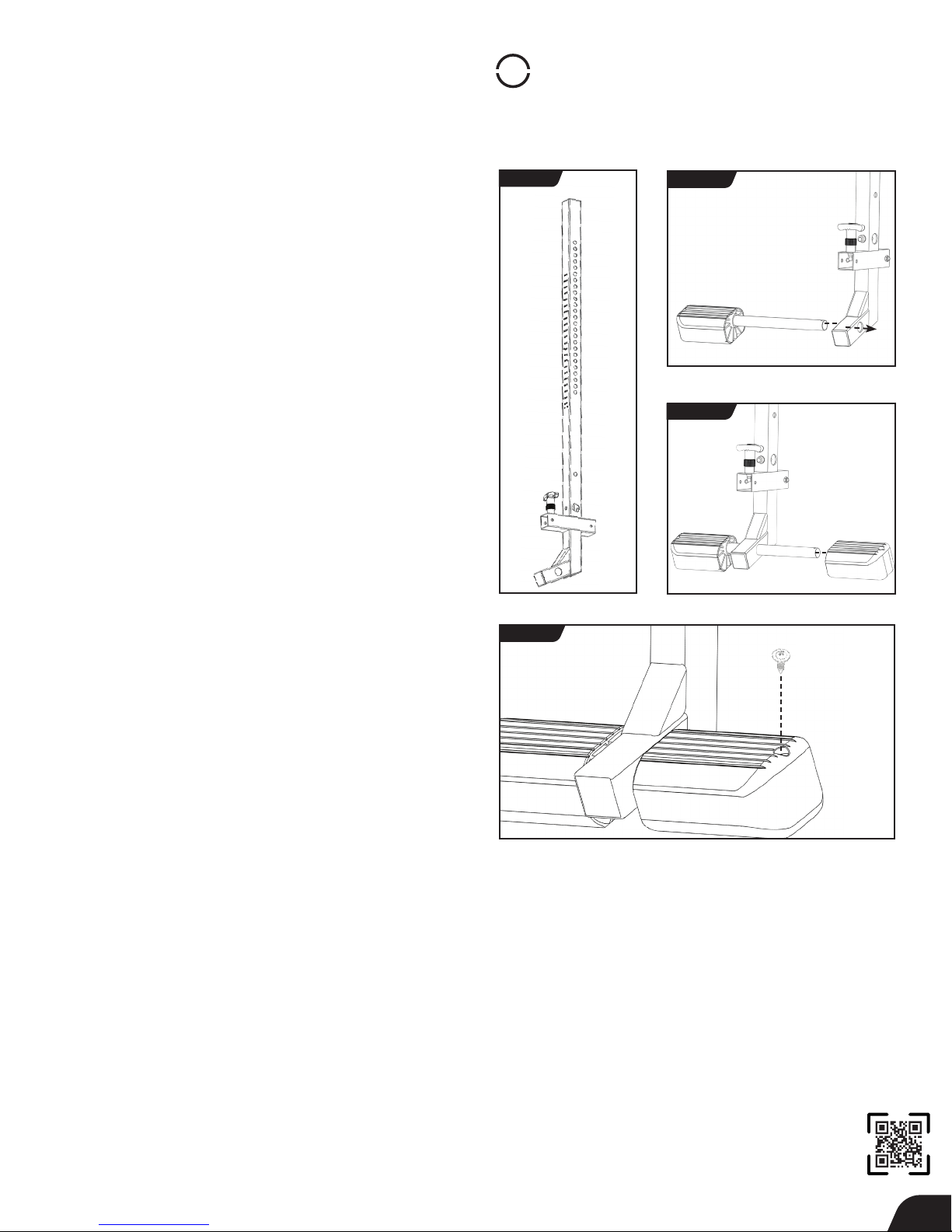
Assemble Ankle Comfort Dial
• Locate the Ankle Comfort Dial Assembly Hardware Kit
(HK1005).
• Slide the Ankle Comfort Dial Bar with pre-assembled Ankle
Comfort Dial into the hole at the front base of the Main
Shaft (Figure 4a).
• The Ankle Comfort Dial is designed with a High and Low
setting. Position the pre-assembled Dial in the Low Setting
(screw holes facing up) for ease of assembly.
• Slide the separate Ankle Comfort Dial onto the Ankle
Comfort Dial Bar (Figure 4b) and align the screw holes.
• Secure with the screw and tighten with the screwdriver
provided (Figure 5).
NOTE: Refer to the Owner’s Manual for a complete
description of the Ankle Comfort Dial settings.
FIGURE 4
FIGURE 4a
FIGURE 4b
FIGURE 5
7
Page 10
STEP
3
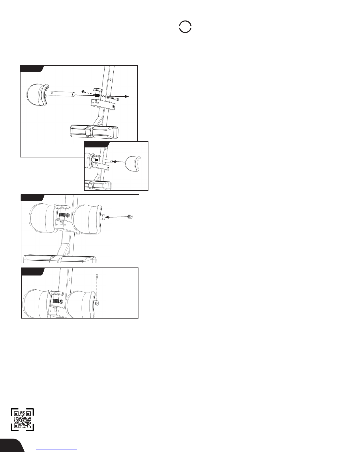
Assemble Rear Ankle Bar
FIGURE 6
FIGURE 7
FIGURE 6a
• Locate the Rear Ankle Bar Assembly Hardware Kit (HK1003).
• Insert the Rear Ankle Bar into the large hole at the back of the
Main Shaft. Ensure that the embossed Ergo Embrace logo on the
preassembled Heel Cup is on top (Figure 6).
• Insert the bolt from the rear of the Main Shaft to secure the Rear
Ankle Bar (Figure 6), and fasten with the washer and nut using the
wrenches provided.
• Slide the separate heel cup, with the embossed Ergo Embrace
logo on top, onto the open end of the Rear Ankle Bar (Figure 6a).
TIP: To assist with assembly, repeatedly rotate the Heel Cup while
pushing it onto the Rear Ankle Bar.
• Align the pre-drilled screw hole in the Rubber Plug with the screw
hole in the Rear Ankle Bar. Insert the Rubber Plug into the open
end of the Rear Ankle Bar (Figure 7).
TIP: You may want to use a rubber mallet to assist with assembly.
• Secure the Rubber Plug with the screw using the screwdriver
provided (Figure 8). If the screw does not tighten easily, you may
need to reposition the alignment of the Rubber Plug.
™
FIGURE 8
8
Page 11
STEP
4
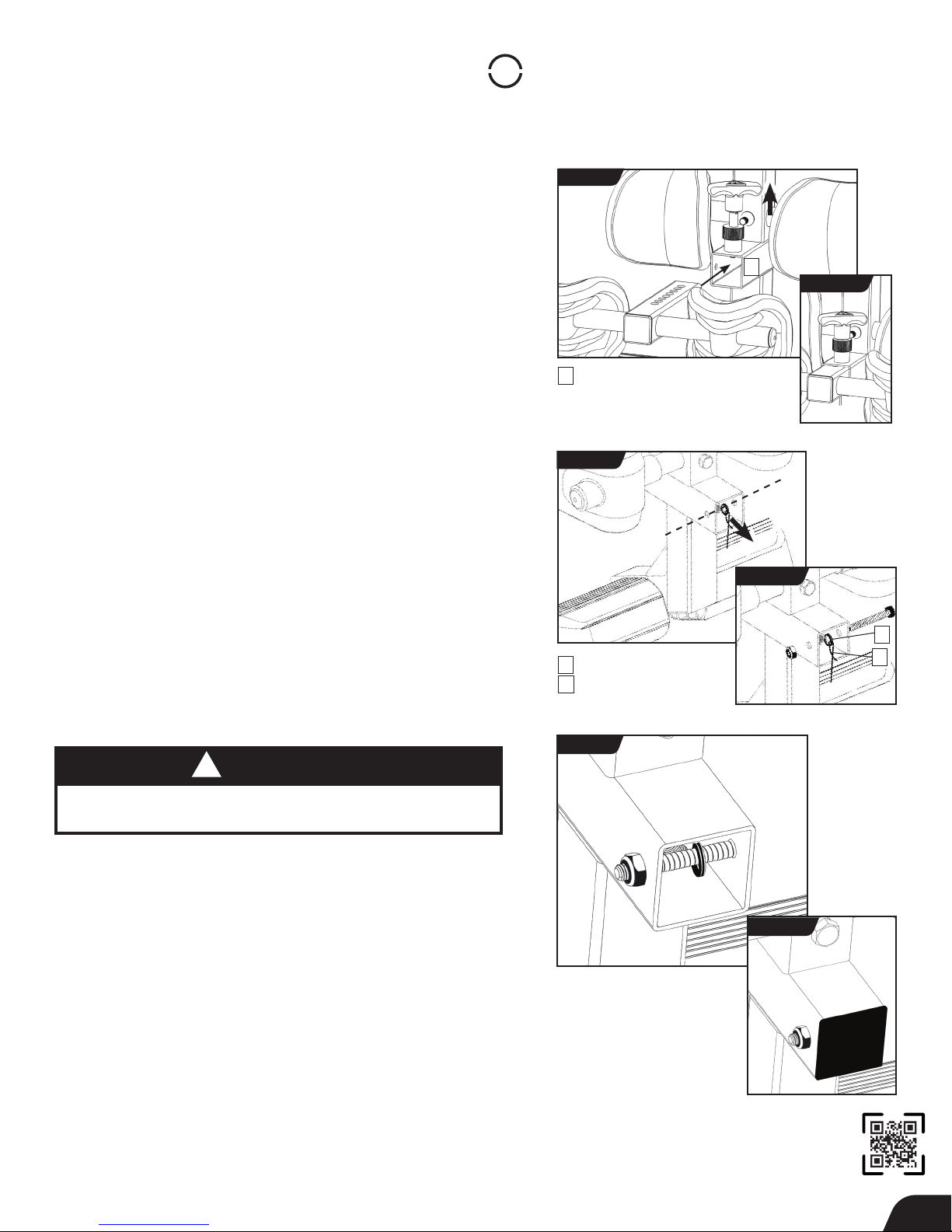
Assemble Front Ankle Bar to Main Shaft
NOTE: Extending out from the Front Ankle Bar, you will see a
temporary plastic zip-tie fastened to the loops of the Retainer
Spring with Cable. This is provided to assist with the
assembly process.
• With hole settings of the Front Ankle Bar facing up, insert the
temporary plastic zip-tie and Front Ankle Bar into the Front Ankle
Bar housing (Figure 9) of the Main Shaft.
• Pull up on the T-Pin Lock to allow the Front Ankle Bar to insert all
the way into the housing. Release the T-Pin to engage in the hole
setting closest to the Front Ankle Cups (Figure 9a).
• Turn over the Main Shaft (Figure 10). From the back side of the Front
Ankle Bar housing, pull the plastic zip-tie to stretch the Retainer
Spring and Cable Loops so that they align with the bolt holes in the
back of the Front Ankle Bar housing.
• Insert the Bolt through the hole in the outer side of the housing,
through both the Retainer Spring and Cable Loops, and through the
hole in the other side of the housing (Figure 10a).
• Release your hold on the plastic zip-tie. Secure the Bolt with the
Nut (Figure 11) using the 10/13mm Open-Ended Wrenches provided.
FIGURE 9
Front Ankle Bar Housing
1
FIGURE 10
1
FIGURE 9a
FIGURE 10a
• Cut the long segment of zip-tie off so that it will not interfere with
the function of the Retainer Spring. Be careful not to damage the
Retainer Spring or Cable.
• Cover the open end of the Front Ankle Bar Housing with the End
Cap (Figure 11a).
!
WARNING
Failure to assemble the T-Pin Ankle Lock System
properly could result in serious injury or death!
Retainer Spring & Cable Loop
1
Temporary Zip-Tie
2
FIGURE 11
FIGURE 24
1
2
FIGURE 11a
9
Page 12
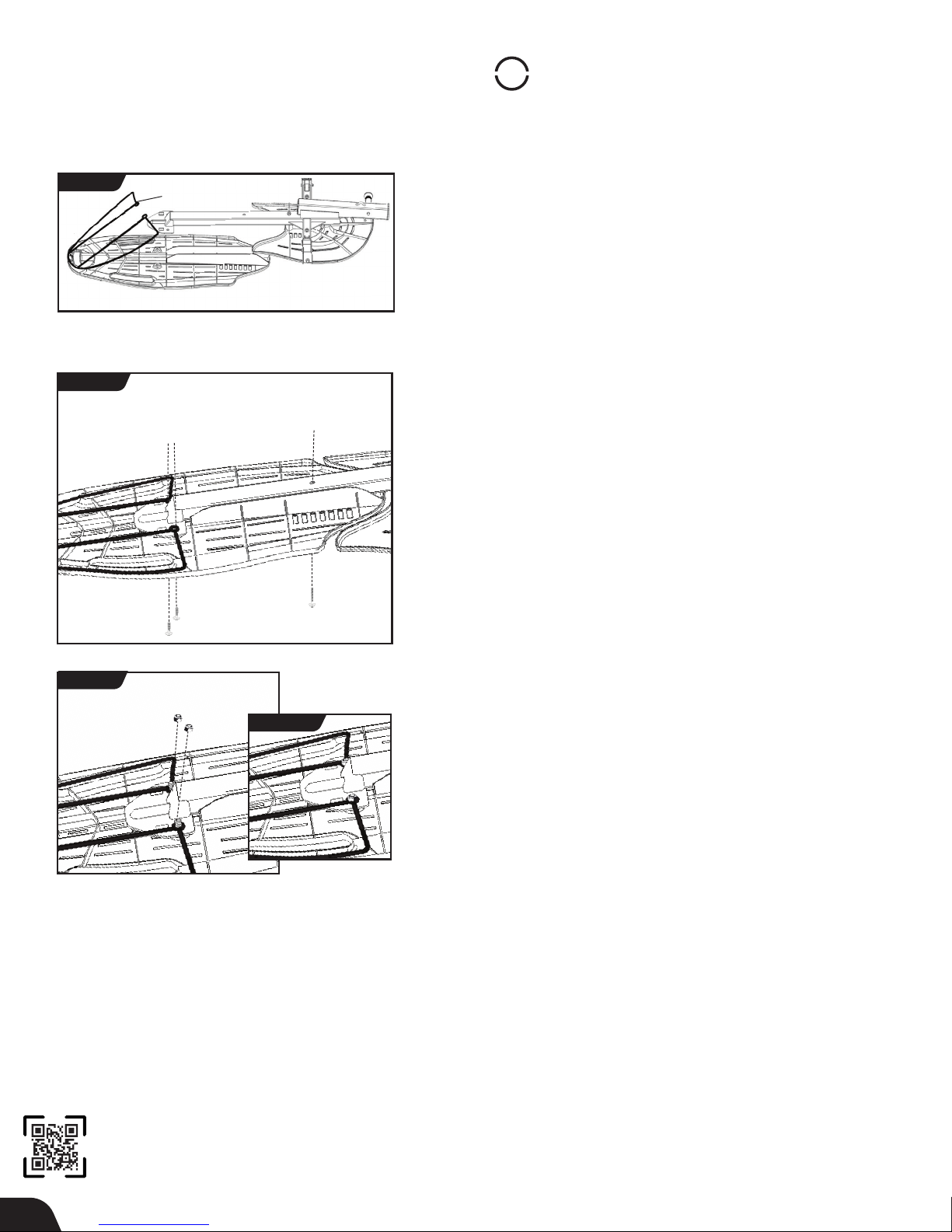
STEP
5
Table Bed Assembly
FIGURE 12
FIGURE 13
Bed Frame Extension
Upper Portion
Upper Holes / Shorter Bolts
Lower Portion
Lower Hole / Longer Bolt
NOTE: Do not detach the Bed Frame Extension from the clips.
• Locate the Table Bed Assembly Hardware Kit (HK1006)
• Lay the Upper and Lower Portions face down on the floor (Figure 12).
• Gently lift the base of the pre-assembled Bed Frame Extension to
slide the Lower Portion and Frame onto the Upper Portion. Align the
shaft of the frame into the plastic track of the Upper Portion
(Figure 13).
• Align the bolt holes of the upper part of the frame (triangle-shaped
area) to the bolt holes on the Upper Portion. Release the Bed Frame
Extension so that it rests on top of the bolt holes (Figure 14).
• Reaching underneath, insert one of the shorter bolts through one
of the holes in the Upper Portion and hold in place. Slide one of the
Bed Frame Extension loops over the bolt and hand-tighten with a nut
(Figures 14 & 14a). Repeat with the other shorter bolt.
• Reaching underneath, insert the longest bolt into the lower hole and
hand-tighten with a nut.
• To fully tighten all three nuts to the bolts, insert the Allen Wrench into
the bolt heads and tighten the nuts using a 10/13mm Open-Ended
Wrench.
FIGURE 14
FIGURE 14a
10
Page 13
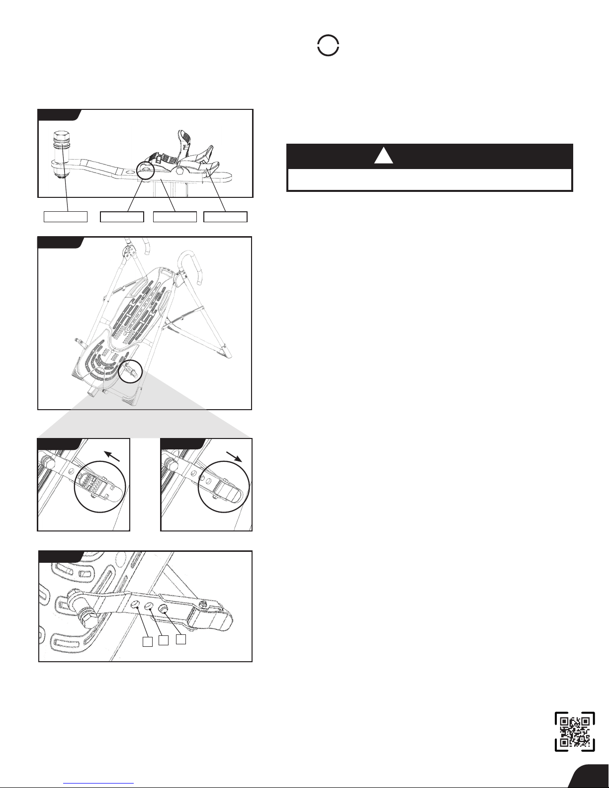
STEP
6
Assemble Roller Hinges to Table Bed
FIGURE 15
Pivot Pin
FIGURE 16
UNLOCKED
Bracket Pin
Bracket
LOCKED
Cam Lock
• Familiarize yourself with the 3-Hole Roller Hinge and Cam Lock
terms (Figure 15).
!
WARNING
NEVER disassemble the Roller Hinge Pivot Pin.
• For ease of assembly, rest the Table Bed against the Crossbar
(Figure 16) at the front of the A-Frame.
• On one side of the Table Bed, lift and hold the Cam Lock up all
the way to unlock (Figure 17).
• In your other hand, hold one Roller Hinge near the Pivot Pin.
With the Pivot Pin facing out (away from the Table Bed), slide the
bottom of the Roller Hinge between the Cam Lock and the Bracket.
TIP: Make sure that the Cam Lock is completely open when inserting
the Roller Hinge, otherwise assembly will be more difficult.
• Engage one of the holes in the Roller Hinge over the Bracket Pin.
Figure 19 shows the Roller Hinge installed correctly, with the
Bracket Pin engaged in Setting C.
NOTE: Refer to the Owner’s Manual for an explanation of the hole
settings. If you are unsure, use Setting C to start.
FIGURE 17
FIGURE 19
UNLOCK
A
FIGURE 18
C
B
• Push down on the Cam Lock (Figure 18) to lock it and secure the
Roller Hinge.
• Repeat on other side. Make sure the Roller Hinges are in the
same hole setting on both sides.
LOCK
11
Page 14
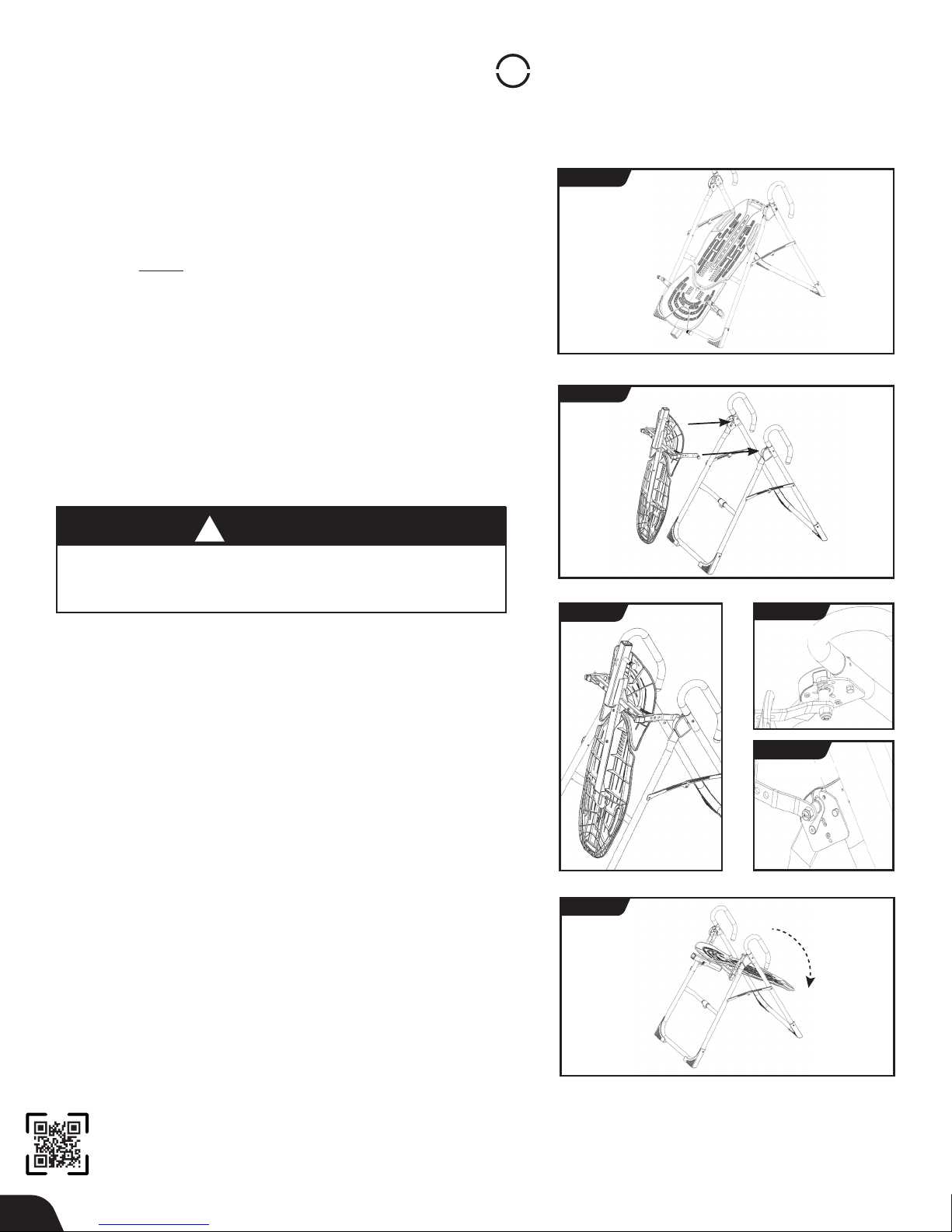
STEP
7
Assemble Table Bed to A-Frame
• Face the front of the A-Frame where the Crossbar is located (Figure 20).
• Grasp both Roller Hinges, right above the Cam Lock, and lift the
Table Bed. Allow the top of the Table Bed to rotate toward the floor,
so that the back of the Table Bed is now facing you and the top of the
Table Bed is in front of the Crossbar (Figure 21).
• Lower each Roller Hinge Pivot Pin into the A-Frame hinge plates, one
side at a time (Figure 22). The Self-Locking Hooks will open to allow the
Pivot Pin into the Hinge Plate slot, then automatically snap closed
over the Pivot Pin.
TIP: You may need to push outward on the Hinge Plate in order for
the second Pivot Pin to lock in place.
• Make sure that each Pivot Pin is seated at the base of the slot in the
Hinge Plates, and that the Self-Locking Hooks have closed over both
Pivot Pins (Figures 22a & 22b).
!
WARNING
Failure of the Self-Locking Hooks to close over both Roller Hinge
Pivot Pins is an indication of improper assembly and if not corrected
could result in serious injury or death!
• Rotate the Table Bed into the use position (Figure 20). Ensure that
it rotates smoothly. See also Image A on Page 12 to ensure
correct assembly.
FIGURE 20
FRONT
FIGURE 21
FIGURE 22
REAR
FIGURE 22a
TOP VIEW
FIGURE 20
FIGURE 22b
INSIDE VIEW
12
Page 15
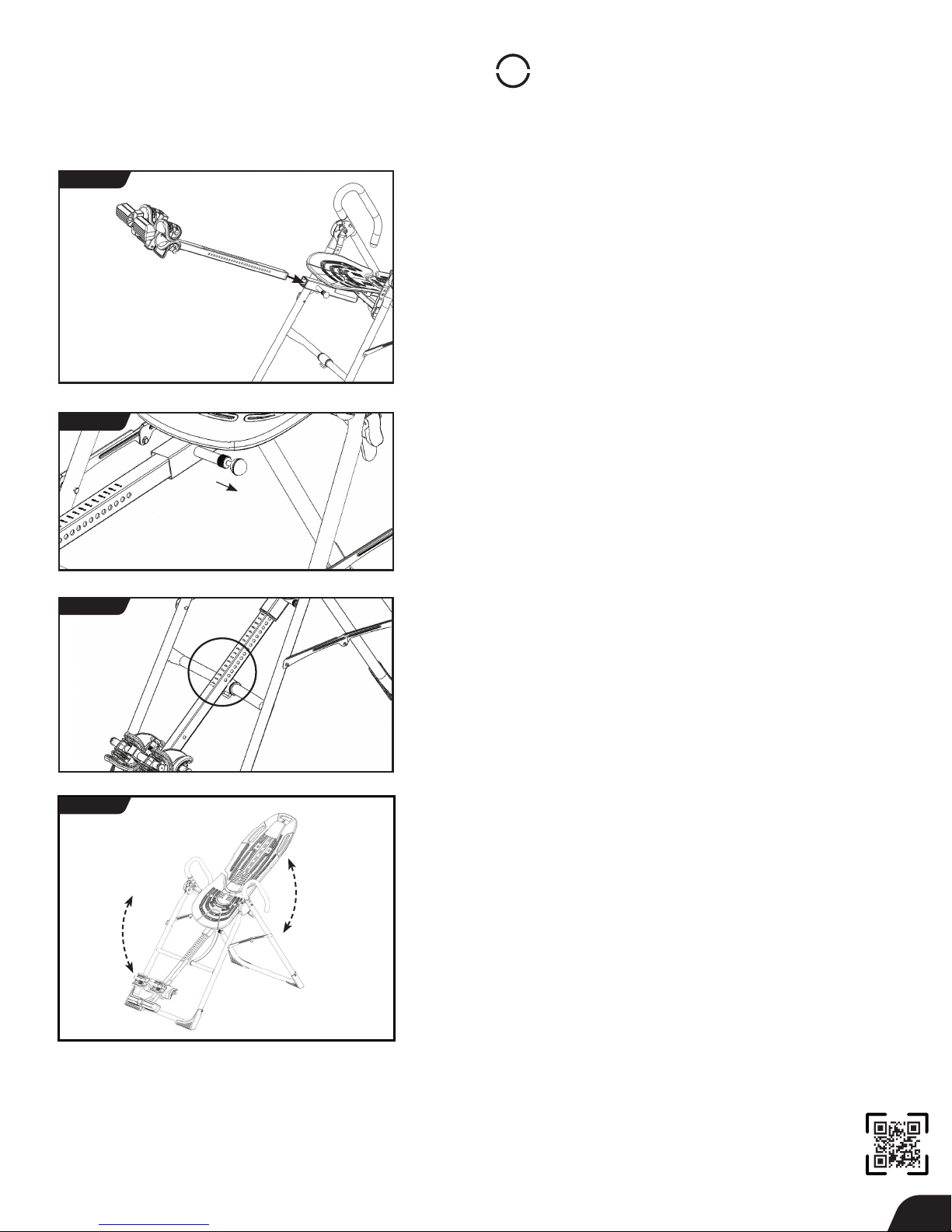
STEP
8
Assemble Main Shaft to Table Bed
FIGURE 24
FIGURE 25
FIGURE 26
• Facing the front of the A-Frame, hold the Main Shaft in your left hand
with the height markings facing up. Slide the end of the Main Shaft
into the Main Shaft Housing (Figure 24), located at the base of the
Table Bed.
• With your right hand, pull out the Height-Selector Locking Pin
(Figure 25) to allow the Main Shaft to slide in further and release
in the desired height setting. Refer to the Owner’s Manual for more
information on selecting your height setting.
• The Main Shaft MUST REST against the Crossbar bumper on the
A-Frame (Figure 26).
IMPORTANT: The Crossbar prevents the Table Bed from rotating
forward when the user steps on the Ankle Comfort Dial. If the
Main Shaft does not rest on the Crossbar bumper as shown in
Figure 26, then the Table Bed has been assembled backwards
onto the A-Frame.
This MUST BE CORRECTED before use. See also Image B on Page 14
to ensure correct assembly.
• Test the inversion table by hand for smooth and steady rotation
(Figure 27) and ensure that all fasteners are secure.
FIGURE 27
13
Page 16
STEP
9
Attach Angle Tether & Head Pillow
Attach Angle Tether
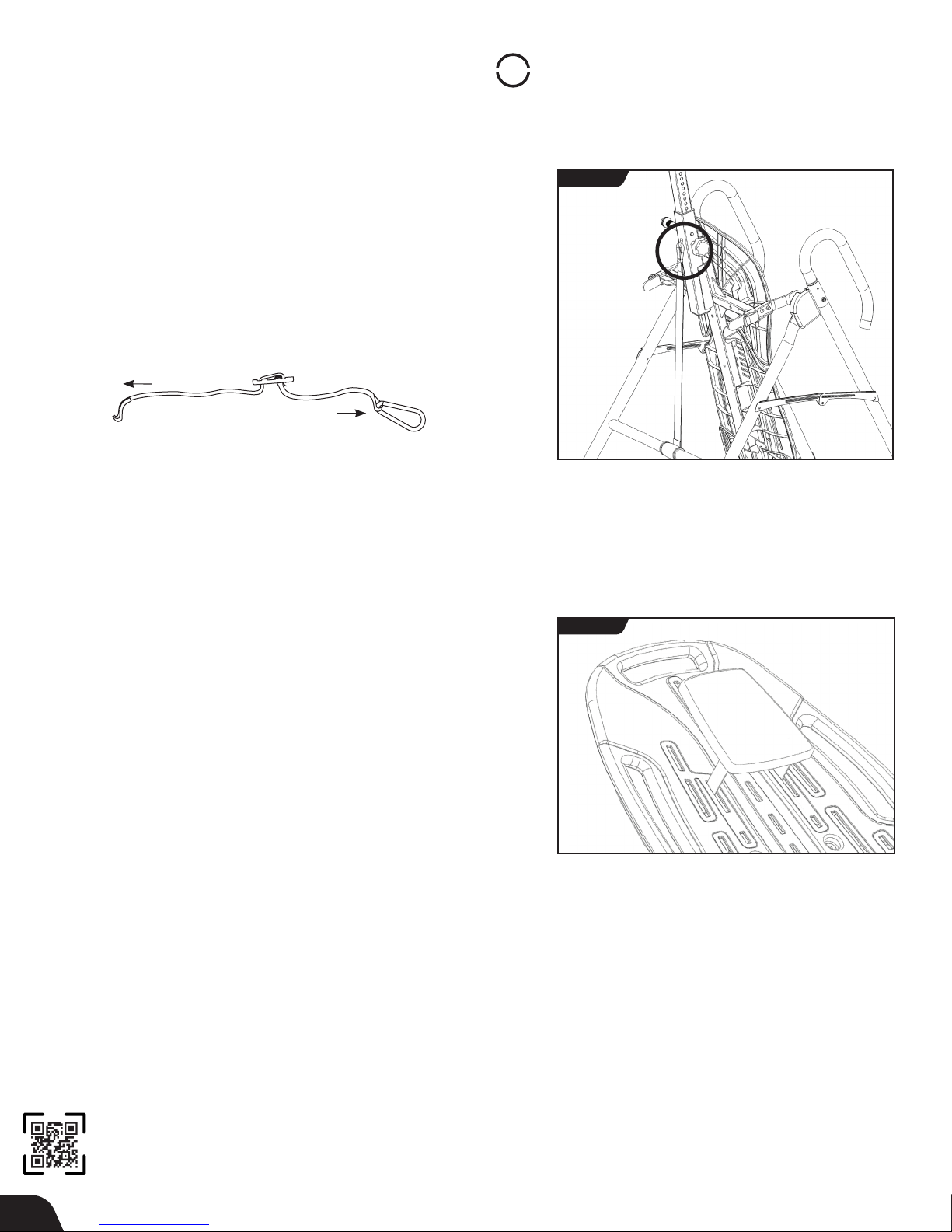
• The tether will come pre-assembled to the A-Frame.
• Unfold the adjustable tether and clip it to the U-Bar on the
underside of the Table Bed (Figure 28).
• Slide the buckle to lengthen or shorten the strap depending on
your desired maximum angle of inversion.
SHORTEN
LENGTHEN
Attach Head Pillow
FIGURE 28
FIGURE 29
Attach the Head Pillow by securing the Velcro Straps through the holes
in the Table Bed (Figure 29). You may customize the position depending
on your preference.
14
Page 17
Misassembly Check
!
WARNING
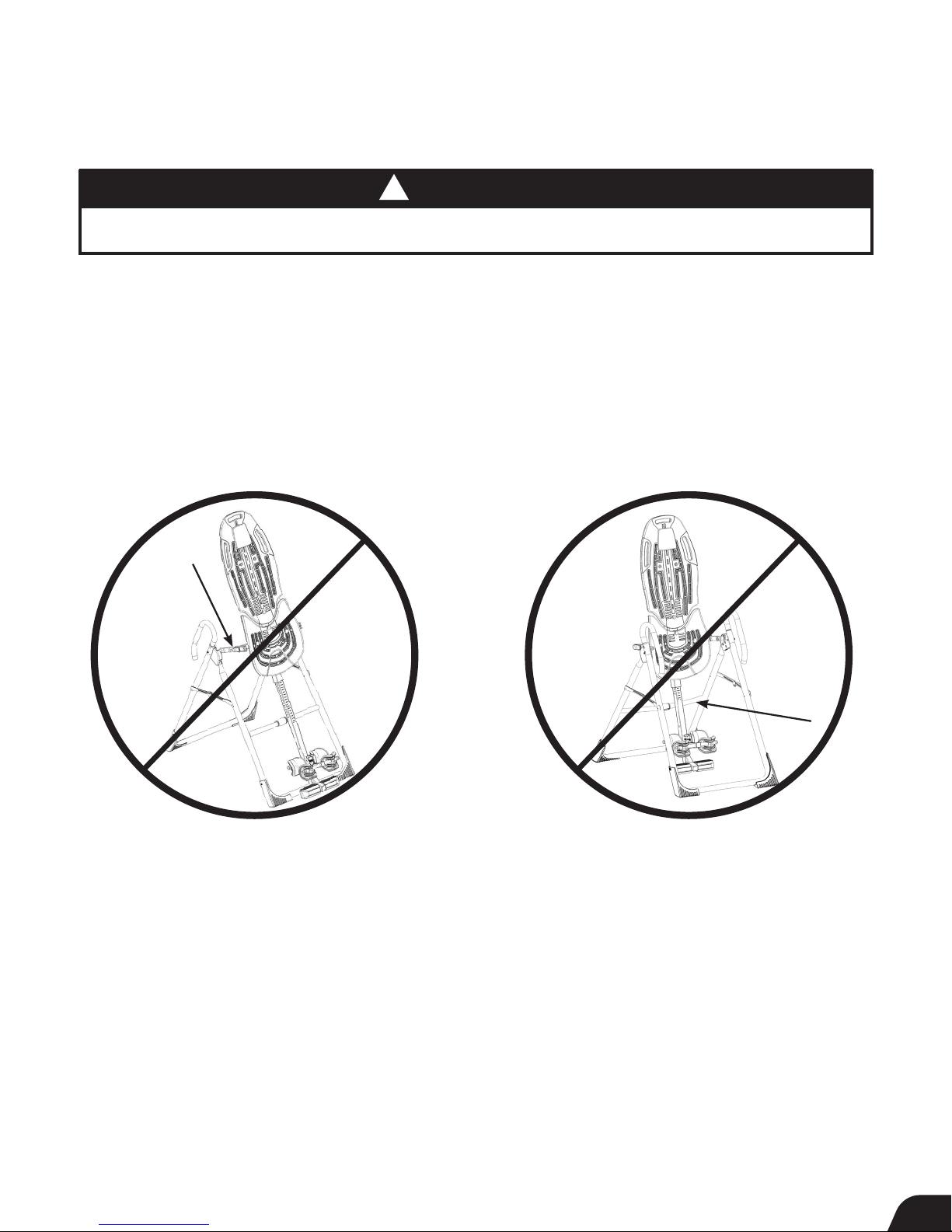
If your Teeter Inversion Table looks like either of these images, your inversion table has
been misassembled and is unfit for use. Improper assembly could result in serious injury or death!
Image A
Go back to Step 6 for instruction.
Demonstrates that the Roller Hinges have been
assembled upside down into the Table Bed
and must be corrected.
Image B
Go back to Step 7 for instruction.
Demonstrates that the Table Bed has been
assembled into the A-Frame backwards so the
Main Shaft is not resting on the Crossbar and must be corrected.
15
Page 18
Before Inverting
FIGURE 24
FIGURE 27
FIGURE 27a
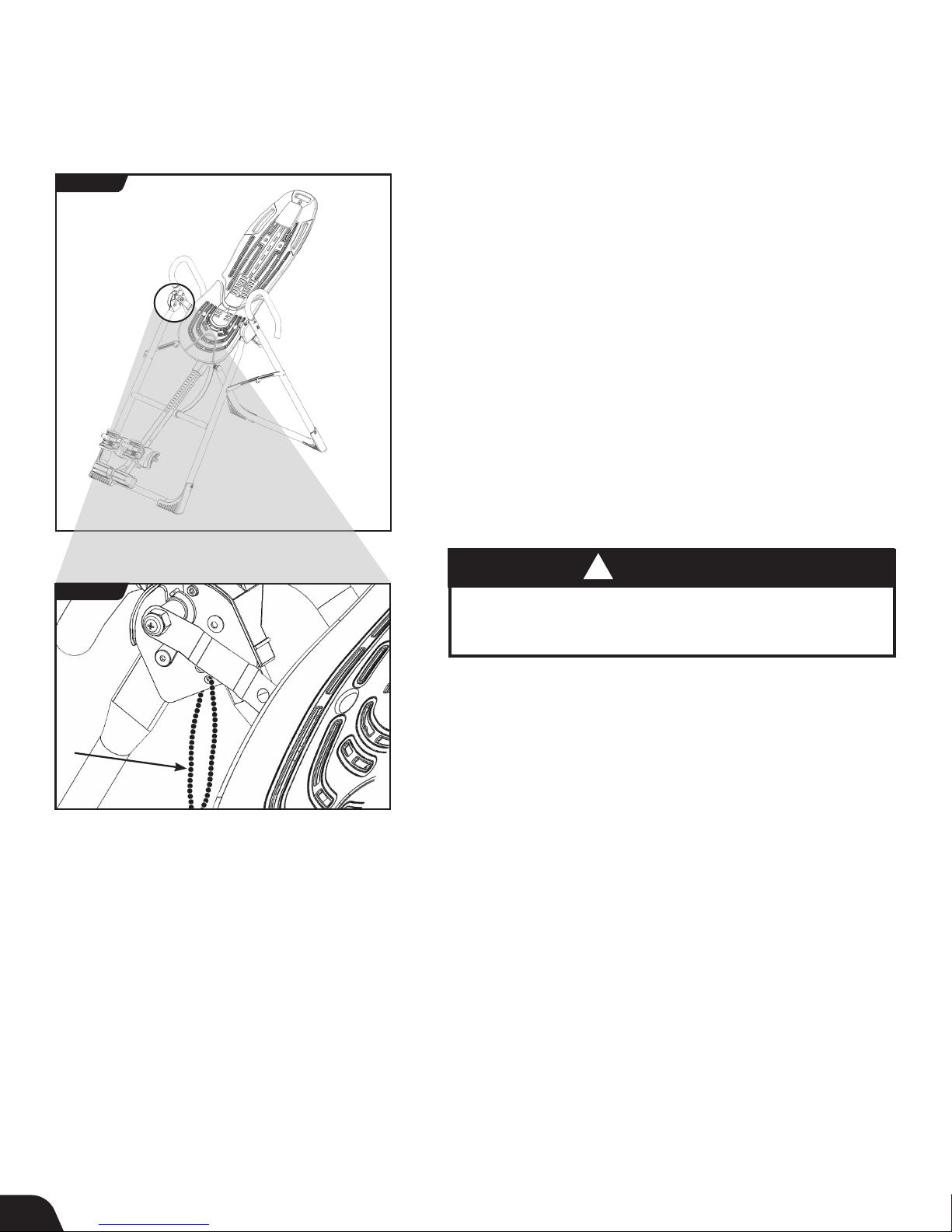
Ensure Owner’s Manual is Attached
The Owner’s Manual contains important information on how to use your
Teeter Inversion Table, including how to personalize the user settings,
properly secure and release the Ankle Lock System, and test and adjust
the rotation control.
• If not already attached, thread the provided metal chain through
the pre-punched hole in the upper corner of the Owner’s Manual.
• Secure the chain to the A-Frame through the designated hole in the
Hinge Plate (Figure 27 & 27a). Allow the Owner’s Manual to hang freely
on the outside of the A-Frame Spreader Arms so it doesn’t interfere
with the rotation of the Table Bed.
IMPORTANT: Once attached to the A-Frame, DO NOT remove the
Owner’s Manual. It should remain permanently attached to your
inversion table to serve as a reference for all users in regards to proper
adjustment and use of the equipment.
!
WARNING
Read the Owner’s Manual thoroughly before using your
Teeter Inversion Table. Improper settings could result
in serious injury or death!
View the Remainder of the DVD
The Getting Started DVD is a helpful supplement to the Owner’s Manual,
with easy-to-follow instructions on user settings, how to invert, storage and
maintenance, and even stretching and exercises you can do with
your Teeter.
16
Page 19
The Teeter warranty set forth below and on Teeter’s website applies to US and Canadian customers only.
FULL 5 YEAR WARRANTY
For international customers, please consult your local distributor for warranty information which will vary
depending on country.
During the period starting with the day of retail purchase and continuing for five (5) years, Teeter
FULL
YEAR
5
W
A
Handling and transportation costs related to product warranty service only are covered by this warranty. This warranty does
not cover damage resulting from improper handling, assembly, or installation, repairs made by others, accident, misuse,
or abuse. Under no circumstances shall Teeter, or any other party involved in the sale of this product, have any liability for
incidental or consequential damage arising from breach of an express or implied warranty on any Teeter product.
EXCEPT AS SET FORTH ABOVE, NO WARRANTY IS GIVEN WITH RESPECT TO ANY TEETER PRODUCT, AND ALL EXPRESS
WARRANTIES ARE DISCLAIMED. This warranty shall be governed by the laws of the State of Washington, USA. To
the extent this warranty is found not to be enforceable, it shall be deemed revised to the extent necessary to make it
enforceable. This warranty and any controversy or claim arising out of this warranty or its interpretation shall be governed
by the laws of the State of Washington, USA. Any controversy or claim arising out of or relating to this warranty, its
interpretation, or any alleged breach thereof, which cannot be amicably settled between Teeter and the owner within
sixty (60) days of written notice by the aggrieved party to the other, shall be finally settled by arbitration submitted to
three (3) arbitrators selected from the panels of the arbitrators of the American Arbitration Association located closest to
Teeter’s principal place of business.
Y
T
N
R
A
R
extends to the owner a repair and replacement warranty against manufacturing defects in
materials, workmanship, fabrics and padding. Teeter will repair or replace any such defect and will
pay the costs of all parts, labor and transportation. If a repair or replacement is not commercially
practical or cannot timely be made, then Teeter will, at the original Purchaser’s option, replace
with a comparable product or refund the purchase price.
Some states do not allow the exclusion of incidental or consequential damage from a warranty, so the above limitation or
exclusion may not apply to you. Some states do not allow limitations on how long an implied warranty lasts, so the above
limitation may not apply to you. This warranty gives you specific legal rights, and you may also have other rights which may
vary from state to state. This warranty is completely transferable to any and all future owners of this product, provided no
alterations have been made to the product.
HOW TO SUBMIT YOUR REGISTRATION:
Step 1
Fill out this information for your own records.
Step 2
Go online to teeter.com to register your warranty.
Date of Purchase
Product & Model
Dealer Name
Serial No.
If you are unable to go online, you can request a warranty card to be mailed to you by calling Customer Service at 800-847-0143.
Please DO NOT mail this to Teeter.
PLEASE RETAIN THIS FOR YOUR RECORDS
17
Page 20

This product is Listed by
Underwriters Laboratories Inc.
Representative samples of this
product have been evaluated
by UL and meet applicable
safety standards.
This product is Listed by
Underwriters Laboratories Inc.
Representative samples of this
product have been evaluated
by UL and meet applicable
safety standards.
This product is Listed by
Underwriters Laboratories Inc.
Representative samples of this
product have been evaluated
by UL and meet applicable
safety standards.
Roger Teeter
Founder & Innovator
If you have any trouble assembling the equipment, or questions
about its use, please contact customer service.
Check out the selection of products and accessories
available at teeter.com!
U.S. and Foreign Patents Apply. Teeter and Teeter logo are registered trademarks of Teeter. Specifications subject to change without notice.
© COPYRIGHT 2015 Teeter. International Law Prohibits Any Copying. NX1725 0615-2
USA: Teeter
nd
9902 162
Puyallup, WA 98375
Toll Free: 800-847-0143
Fax: 800-847-0188
teeter.com | [email protected]
St. Ct. E.
Any modification to this device will void the UL Listing.
Underwriters Laboratories Inc.
Representative samples of this
This product is Listed by
product have been evaluated
by UL and meet applicable
safety standards.
International: Teeter International, Ltd.
Gor-Ray House
758 Great Cambridge Rd
Enfield
Middlesex EN1 3GN
United Kingdom
teeterintl.com | [email protected]
EC
Medical Device Safety Service
GmbH
Schiffgraben 41
30175 Hannover
Germany
Tel. +49 511 62628630
REP
 Loading...