

Page 1
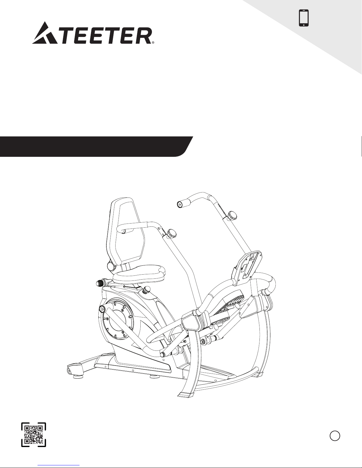
FreeStep™
Elliptical Recumbent Cross Trainer
Assembly Instructions & User Guide
For Zero-Impact Cardio and Muscle Toning Workouts
NEW!
Follow along with
your smartphone
to make assembly
even easier!
To download and print Teeter FreeStep™ instructions, visit the product support page at teeter.com.
* Specications may vary from this image and
are subject to change without notice.
EN
Page 2

Congratulations on your purchase of the Teeter FreeStep
follow, read, and fully understand the Assembly Instructions & User Guide. The FreeStep
use, intended to provide a comfortable, zero-impact workout for adults.
For step-by-step, 3D interactive instructions, download BILT (a FREE mobile app) to your smartphone to follow along.
See Page 5 for instructions on how to download BILT.
To register your product warranty, go to teeter.com/Support/Warranty-Registration
If you have any questions concerning assembly or if any parts are missing, DO NOT RETURN THE ITEM TO THE STORE
OR CONTACT THE RETAILER. Our dedicated customer service experts can help! Contact Teeter Customer Service
at 800.847.0143, or via online forms or Live Chat at teeter.com.
™
! In order to utilize this product to its fullest extent, it is critical that you
™
is a multiple user, reusable device for home
Assembly Instructions
Important Safety Instructions ........................ 1
Items for Assembly ...................................2
Understanding Your FreeStep
Safety Warning Labels and Product Specications ...4
Before Beginning Assembly ..........................5
Assembly Steps...................................6 – 11
™
.......................3
User Guide
Use Instructions .................................12 – 15
Warranty and Registration...........................16
Page 3
BEFORE YOU BEGIN: Review all steps before beginning assembly and read all precautions before using the Teeter FreeStep™.
Carefully adhere to the Assembly Instructions and User Guide to help ensure safety and product integrity.
READ ALL INSTRUCTIONS BEFORE USING THE TEETER FREESTEP
IMPORTANT SAFETY INSTRUCTIONS
!
WARNING
FAILURE TO FOLLOW INSTRUCTIONS AND WARNINGS COULD RESULT IN SERIOUS INJURY OR DEATH.
To reduce the risk of injury:
• Read and understand all the instructions, review all other accompanying documents, and inspect the equipment before use.
It is your responsibility to familiarize yourself with the proper use of this equipment and the inherent risks of exercise equipment
if these instructions are not followed, such as, pinching, entrapment, equipment failure, or aggravating a pre-existing medical
condition. It is the responsibility of the owner to ensure that all users of the product are fully informed about the proper use of
the equipment and all safety precautions.
• ALWAYS consult with your doctor before beginning any exercise or weight-loss program, especially if you are over the age of
35 or have any known pre-existing medical problems. This may include injury or illness, but also the side effects of any drug or
supplement (prescribed or over-the-counter).
• The instructions and advice presented in this User Guide are in no way intended as a substitute for medical advice or counseling.
• DO NOT continue using the equipment if you feel pain, discomfort, shortness of breath, chest tightness, or become light-headed
or dizzy while exercising. STOP and seek medical advice. Call 911 if you are having an emergency health condition.
• DO NOT use if you are over 300 lbs. (136 kg). Structural failure and physical injury could occur.
• ALWAYS ensure that all adjustable features are accurately adjusted to the users’ body proportions and all parts are fully tightened
and secured before use. ALWAYS hold the Handles or Seat Handles when mounting, dismounting, or using equipment.
• DO NOT place hands or feet near linkages while in use. The linkages are ywheel driven and can cause serious injury, entrapment,
or death. DO NOT allow pets or children to approach the linkage while it is moving.
• DO NOT place any objects within a 24” (61cm) radius of the machine. Do not place any objects or body parts behind the pivot area
of the pedals.
• ALWAYS reduce pedal speed in a controlled manner. Pedals continue to spin when you stop pedaling.
• DO NOT allow children to use this machine. Keep children, bystanders, and pets away from machine at all times and DO NOT
allow children to be left unattended in the same room at the equipment. The FreeStep
reduced physical, sensory or mental capabilities, unless they are given supervision and instruction concerning use of the machine
by a person responsible for their safety.
• ALWAYS wear appropriate clothing while exercising with the machine. DO NOT wear loose clothing that could get entangled in
the equipment. ALWAYS wear athletic shoes to protect feet while exercising with the machine.
• ALWAYS store indoors and on a level surface. This equipment is not intended for outdoor use.
• DO NOT use in any commercial, rental or institutional setting. This product is intended for home-use only.
• ALWAYS use this equipment only for its intended use as described in this manual. DO NOT use attachments not recommended
by manufacturer.
• DO NOT drop or insert any object into any opening or place any sharp objects near the equipment. Keep body parts, hair, loose
clothing and jewelry clear of all moving parts.
• DO NOT operate equipment while under the inuence of drugs, alcohol, or medication that may cause drowsiness or disorientation.
• ALWAYS inspect the equipment prior to use. Make sure all fasteners are secure and adjustable settings are secure.
• ALWAYS replace defective components immediately and/or keep the equipment out of use until repair.
• ALWAYS position equipment on a level surface and away from water or ledges that could lead to accidental immersion or falls.
• ALWAYS use a damp cloth when cleaning. DO NOT use abrasive soaps or solvents to clean as this could cause damage to the machine.
• Refer to additional warning notices posted on the equipment. If a product label or User Guide should become lost, damaged or
illegible, contact Customer Service for replacement.
™
is not intended for use by persons with
™
1
SAVE THESE INSTRUCTIONS
Page 4
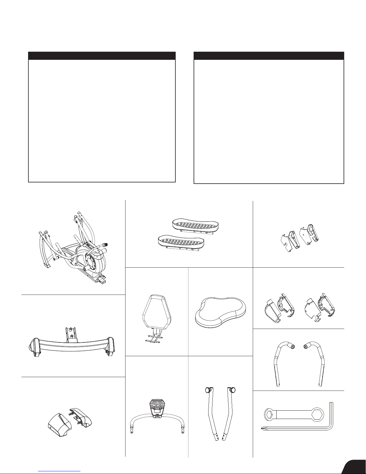
Items for Assembly
Items not shown to scale. Hardware drawings located on the Hardware Kit insert.
ITEM NO. ITEM NAME
Base
SE1101 Base
Rear Stabilizer
SE1102 Rear Stabilizer
HK1042 Step 1a Hardware Kit
Rear Stabilizer Cover Set
SE1103 Rear Stabilizer Cover (2)
HK1043 Step 1b Hardware Kit
Pedals
SE1104 Pedal (2)
HK1044 Step 2 Hardware Kit
Seat Back Assembly
SE1105 Seat Back Assembly
HK1045 Step 3a Hardware Kit
Lower Seat
SE1106 Lower Seat
HK1046 Step 3b Hardware Kit
Base
ITEM NO. ITEM NAME
Console Front Support Bar
SE1107 Console Front Support Bar
HK1047 Step 4a Hardware Kit
Handle Support Tubes
SE1108 Handle Support Tube (2)
HK1048 Step 4b Hardware Kit
Pedal Arm Joint Cover Sets
SE1109 Pedal Arm Joint Cover (4)
HK1049 Step 5 Hardware Kit
Upper Front Leg Cover Set
SE1110 Upper Front Leg Cover (4)
HK1049 Step 5 Hardware Kit
Handles
SE1111 Handle (2)
Tools
SE1112 Allen Wrench / Screwdriver
SE1113 Box-Ended Wrench
Pedals
Use with Step 2 Hardware Kit (HK1044)
Pedal Arm Joint Cover Sets
Use with Step 5 Hardware Kit
(HK1049)
SE1101
Rear Stabilizer
Use with Step 1a Hardware Kit (HK1042)
SE1102
Rear Stabilizer Cover Set
Use with Step 1b Hardware Kit (HK1043)
Seat Back Assembly
Use with Step 3a
Hardware Kit (HK1045)
SE1105
Console Front
Support Bar
Use with Step 4a
Hardware Kit (HK1047)
SE1104
Lower Seat
Use with Step 3b
Hardware Kit (HK1046)
SE1106
Handle Support Tubes
Use with Step 4b
Hardware Kit (HK1048)
SE1109
Upper Front Leg Cover Sets
Use with Step 5 Hardware Kit
(HK1049)
SE1110
Handles
SE1111
Tools Provided for Assembly
SE1103
Allen Wrench /
Screwdriver
SE1107 SE1108 SE1112 SE1113
Box-Ended
Wrench
2
Page 5
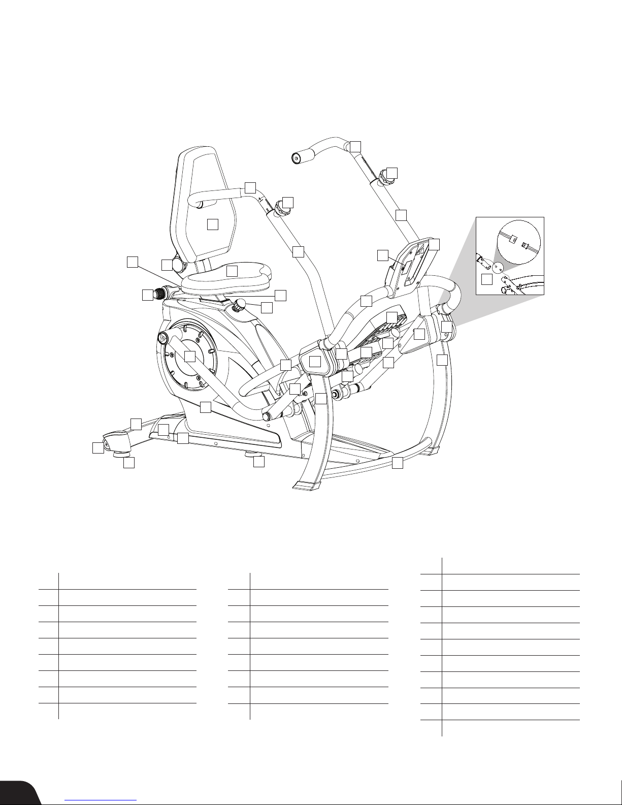
Understanding Your Teeter FreeStep
Before reading further, study the drawing below to familiarize yourself with the
important components of your Teeter FreeStep
™
.
™
24
23
24
23
18
12
25
7
Back
3
27
29
28
4
18
14
13
11
17
5
6
15
9
21
20
10
26
16
21
20
19
22
9
10
19
22
1
Left
2
27
Right
8
Front
Identifying Parts and Components
1 Base
2 Main Support Tube
3 Rear Stabilizer
4 Rear Stabilizer Cover Set
5 Seat Post
6 Height Adjustment Knob
7 Seat Handle
8 Front Crossbar
9 Pedals
3
10 Base Pedal Arms
11 Lower Seat
12 Seat Back Assembly
13 Console
14 Battery Compartment
15 Console Front Support Bar
16 Lower Console Support Tube
17 Speed Sensor Wire
18 Handle Support Tubes
19 Upper Pedal Arm
20 Pedal Arm Joint Cover Sets
21 Upper Front Leg Cover Sets
22 Upper Front Leg
23 Handle Adjustment Knobs
24 Handles
25 Transport Wheels
26 Linkage
27 Leveling Feet
28 Seat Back Adjustment Knob
29 Resistance Adjustment Knob
Page 6
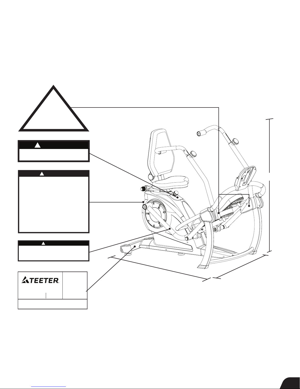
Safety Warning Labels and Product Specications
SE1053 1017-0
Important: Please review all labels and supporting materials before using your FreeStep™.
This drawing indicates the locations of the warning labels found on your product. If a label is missing, illegible or is removed,
contact Teeter Customer Service to request a complimentary replacement label.
Note: Image and labels below are not shown in actual size.
!
WARNING
PINCH POINT - DO NOT PLACE
HANDS OR FEET HERE
!
Ensure that the knob is fully tightened
WARNING
into a hole setting before use.
Replace labels if damaged, illegible or removed.
SE1052 1017-0
!
SERIOUS INJURY OR DEATH MAY OCCUR IF
PRECAUTION IS NOT TAKEN. To reduce this risk:
• READ and understand the Assembly & User Instructions
before attempting to use.
• ALWAYS consult a physician before starting an exercise
regimen. DO NOT continue to use if you feel unusual pain,
dizziness, shortness of breath, chest tightness or discomfort.
• DO NOT allow children to use this machine or leave them
unattended with the product. Keep children, bystanders
and pets away when in use.
• ALWAYS reduce pedal speed in a controlled manner.
Pedals continue to spin when you stop pedaling.
• Keep body parts, hair, loose clothing and jewelry clear of
all moving parts.
• Weight Capacity: 300 lb (136 kg). For consumer,
indoor Home-Use Only.
SERIOUS INJURY OR DEATH MAY OCCUR IF PRECAUTION IS
NOT TAKEN. To reduce this risk:
• DO NOT allow children or pets to approach the equipment while in use.
NEVER place hands or feet near linkages while in use. The linkages are
flywheel driven and can cause serious injury, entrapment or death.
9713 233rd Avenue East
Bonney Lake, WA 98391
SERIAL # / EN SÉRIE / NÚMERO DE SERIE
SSE-
WARNING
ALWAYS use on a level surface.
Replace labels if damaged, illegible or removed.
!
WARNING
Replace labels if damaged, illegible or removed.
FreeStep
™
800.847.0143
teeter.com
SE1050 1017-0
SE1054 1017-0
US Pats: 7,815,551,
8,562,491, US Patent Pending:
2013/14048302
Canada: Pats Approved
Application 2696901
(issues 11-2015)
Europe: Application 08830164.3
CN (Utility):
ZL 201220191127.2;
ZL 201420589095.0
CN (Design):
ZL 201233139551.8
Int’l PCT/US2008/076264
SE1070 1117-0
38.0 in (96.5 cm)
54.0 in (137.2 cm)
52.5 in (133.4 cm)
Dimensions: 52.5 x 54.0 x 38.0 in (133.4 x 137.2 x 96.5 cm)
Weight
(approx.): 110.0 lb (50.0 kg)
4
Page 7
Before Beginning Assembly
Unpack and Prepare Your Workspace
• Follow the instructions on the outside of the box for the easiest unpacking process.
• If possible, set up the product at or near the space in which you intend to use it to avoid moving it later.
• Unpack all parts and support materials. Set aside packing materials and clear your work area.
• Locate the Hardware Kit inside the box. It is labeled to correspond with the assembly process.
Plan for:
45
MIN
ASSEMBLY
Making Assembly Even Easier with
For step-by-step, 3D interactive instructions, download BILT (a FREE mobile app) to your
smartphone to follow along. Simply download the BILT app by scanning the QR code
below and then search for your product within the BILT app to get started!
5
Page 8
STEP
1
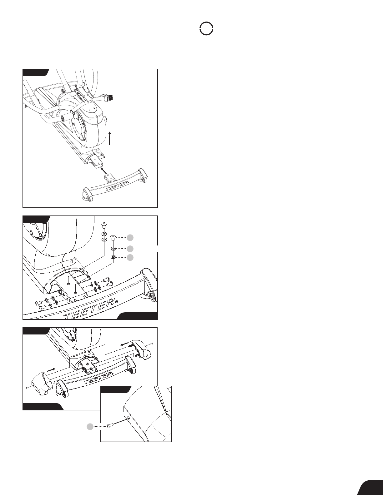
Assemble Rear Stabilizer
FIGURE 1
FIGURE 2
Insert
Lift
Bolt
10 8
Spring Washer
9
Washer
8
NOTE:
• Always hand tighten all the bolts or screws in each step before
fully tightening with the wrench or screwdriver.
• For reference, the Front, Back, Right and Left of the equipment
is labeled on Page 3, Understanding Your FreeStep
™
.
Attach Rear Stabilizer
• Remove the Base from the packaging and position it on a level
surface on the floor.
• Remove the wooden plug from the Main Support Tube in the
back of the Base and discard it.
• Lift the Base slightly from the back and insert the Rear Stabilizer
into the Main Support Tube at the back of the Base (Figure 1).
• Use the Step 1a Hardware Kit to attach the Rear Stabilizer.
First hand tighten 6 × Bolts with 6 × Spring washers and
6 × Washers on the Rear Stabilizer Joint. The Spring Washers should
always be on the outside and closer to the bolt than the Washers.
Use the Allen wrench to fully tighten each bolt (Figure 2).
Attach Rear Stabilizer Cover Set
FIGURE 3
Step 1b Hardware
Machine Screw
• Locate the Rear Stabilizer Cover Set, noting the Right and Left
markings, and the Step 1b Hardware Kit.
• Attach the Right Rear Stabilizer Cover by loosely tightening the 1
x Machine Screw (Figure 3).
Step 1a Hardware
• Attach the Left Rear Stabilizer Cover to the Right by joining the
alignment pegs and pushing together for a snug fit.
• Insert 1 x Machine Screw to secure the Left Rear Stabilizer, then
finish tightening both Machine Screws with the Screwdriver.
FIGURE 3a
61
6
Page 9
STEP
PARTS LIST
ITEM
QTY
NET DIMENSIONS/DESCRIPTION
NOTE
MATERIAL
SHT
5 3 16 248 7
5 3 16 248 7
ITEM
QTY
NET DIMENSIONS/DESCRIPTION
5 3 16 248 7
5 3 16 248 7
2
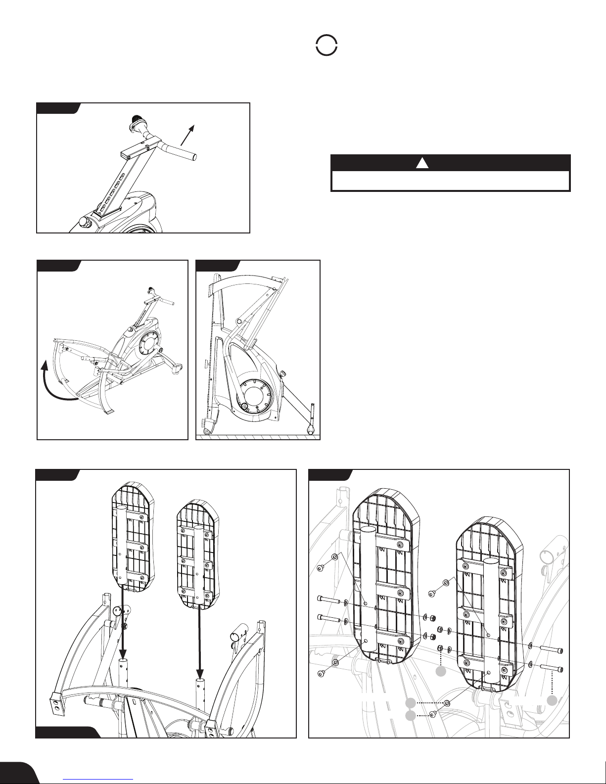
Assemble Pedals
FIGURE 4
FIGURE 5
Pedal Installation
• Locate the Seat Post and raise it to the highest position
by pulling up on the Seat Handle (Figure 4).
!
Pull Handle
Use caution to avoid tipping and when lifting heavy objects.
• To have better access while installing the pedals, position
the FreeStep
Front Crossbar and rotating on the Rear Stabilizer until the
™
to rest on its back side by lifting up on the
Seat Post is resting on the ground (Figure 5 and Figure 6).
FIGURE 6
• Locate the Pedals, noting Right and Left markings. Insert
both Pedals onto the corresponding Base Pedal Arm
(Figure 7).
• Use the Step 2 Hardware Kit to attach the Pedals.
Hand tighten 4 × Large Bolts with 4 × Curved Washers and
4 × Nuts with 4 × Curved Washers as shown (Figure 8).
The Curved Washers should wrap around the shape of the
Base Pedal Arm and Pedal Mount Tube.
• Proceed to hand tighten 4 × Bolts with 4 × Washers as
shown (Figure 8). Proceed to fully tighten all the nuts and
bolts with Allen and Box-Ended wrenches (Figure 8).
CAUTION
Lift and Flip
• Once the Pedals are installed, return the FreeStep
the upright position by lowering the Front Crossbar and
rotating on the Rear Stabilizer.
FIGURE 7 FIGURE 8
10
Nut
™
to
Step 2 Hardware
7
Curved Washer
Bolt
109
10 8
Large Bolt
111
Page 10
STEP
PARTS LIST
ITEM
QTY
NET DIMENSIONS/DESCRIPTION
NOTE
MATERIAL
3
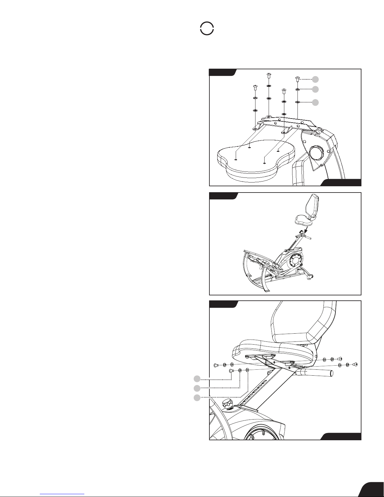
Assemble Seat
Seat Installation
• Locate the Lower Seat and place it upside-down on a flat
surface, such as the edge of a table. Locate the Seat Back
Assembly and line it up with the Lower Seat.
• Use the Step 3a Hardware Kit to assemble the seat parts.
Hand tighten 4 × Bolts with 4 × Spring Washers and 4 × Washers
as shown. Proceed to fully tighten the Bolts with the Allen
Wrench (Figure 9).
• Before attaching the assembled Seat to the Seat Post, make
sure the Seat Post is fully raised for better access, then line the
Seat up with the Seat Post (Figure 10).
• Use the Step 3b Hardware Kit to attach the Seat. Hand tighten
4 × Bolts with 4 × Spring Washers and 4 × Washers as shown.
Proceed to fully tighten the Bolts with the Allen Wrench (Figure 11).
FIGURE 9
FIGURE 10
Bolt
10 8
Spring Washer
9
Washer
8
Step 3a Hardware
Bolt
Spring Washer
Washer
FIGURE 11
10 8
9
8
Step 3b Hardware
8
Page 11
STEP
4
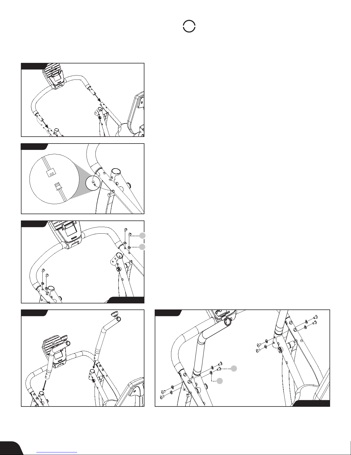
Assemble Supports
FIGURE 12
FIGURE 13
FIGURE 14
Console Front Support Bar Installation
IMPORTANT: Do not pull or pinch the Speed Sensor Wire during
the Console Front Support Bar Installation.
• Locate the Batteries (AA 1.5 V Alkaline) and install them in the
back of the Console in the Battery Compartment, noting
(+) and (-) symbols.
• Ensure that the Speed Sensor Wires remain on the outside. Align
both ends of the Console Front Support Bar with the Lower
Console Support Tube and insert (Figure 12).
• Carefully connect the Speed Sensor Wires (Figure 13).
• Use the Step 4a Hardware Kit to attach the Console Front
Support Bar. Hand tighten 4 × Bolts with 4 × Curved Washers as
shown. The Curved Washers should wrap around the shape of
the Lower Console Support Tube. Proceed to fully tighten the
Bolts with the Allen Wrench (Figure 14).
Handle Support Tube Installation
• Locate the Handle Support Tubes, noting Right and Left
10 8
Bolt
markings. Insert the bottom of each Handle Support Tube into
the top of the Upper Pedal Arm (Figure 15).
109
Curved Washer
Step 4a Hardware
FIGURE 15 FIGURE 16
• Use the Step 4b Hardware Kit to attach the Handle Support
Tubes. Hand tighten 8 × Bolts with 8 × Curved Washers as shown.
The Curved Washers should wrap around the shape of the Upper
Pedal Arms. Proceed to fully tighten the Bolts with the Allen
Wrench (Figure 16).
10 8
Bolt
109
Curved Washer
Step 4b Hardware
9
Page 12
STEP
5
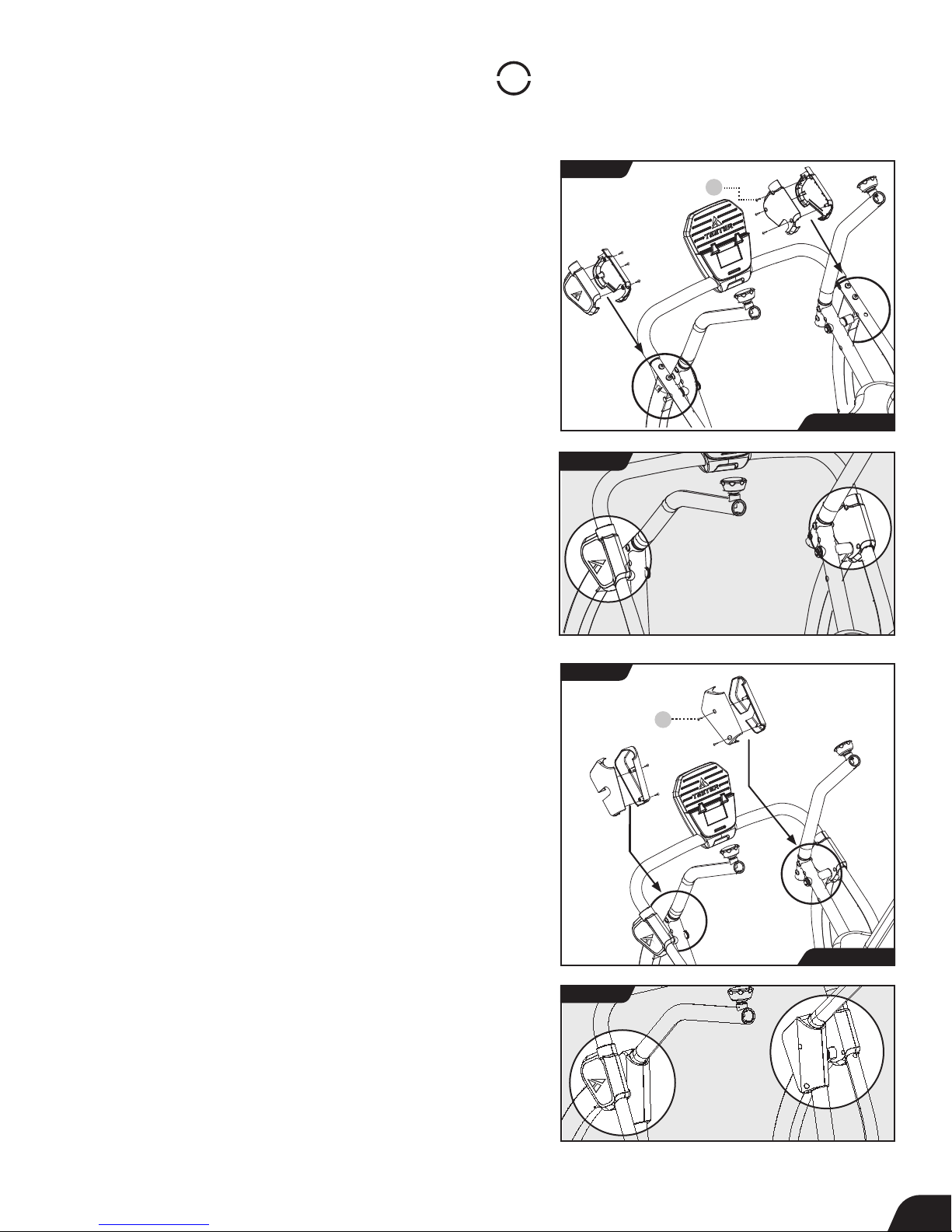
Assemble Cover Sets
Upper Front Leg Cover Sets Installation
IMPORTANT: Make sure the Speed Sensor Wire sits under the Left
Upper Front Leg Cover Set and is not pinched during installation.
TIP: In order to gain better access to the screw holes while
assembling the Upper Front Leg Cover Sets, adjust the position of
the Pedal Arm Joints by pushing forward or pulling backward on
the Handle Support Tubes.
• Locate the Upper Front Leg Cover Sets, noting Right and Left
markings. Pair each set over the corresponding Right and Left
Upper Front Leg (Figure 17).
• Use the Step 5 Hardware Kit to install the Upper Front Leg
Cover Sets. Partially tighten 3 × Phillips Head Screws using the
Screwdriver provided on each set as shown. Ensure they are
properly aligned and proceed to fully tighten the Phillips Head
Screws with the Screwdriver
(Figure 17 and Figure 18).
FIGURE 17
FIGURE 18
Phillips Head
Screw
60
Step 5 Hardware
Pedal Arm Joint Cover Sets Installation
• Locate the Pedal Arm Joint Cover Sets, noting Right and Left
markings. Pair each set over the corresponding Right and Left
Pedal Arm Joints (Figure 19).
• Use the Step 5 Hardware Kit to install the Pedal Arm Joint Cover
Sets. Partially tighten 2 × Phillips Head Screws on each set as
shown. Ensure they are properly aligned and proceed to fully
tighten the Phillips Head Screws with the Screwdriver
(Figure 19 and Figure 20).
FIGURE 19
Phillips Head
Screw
FIGURE 20
60
Step 5 Hardware
10
Page 13
STEP
6
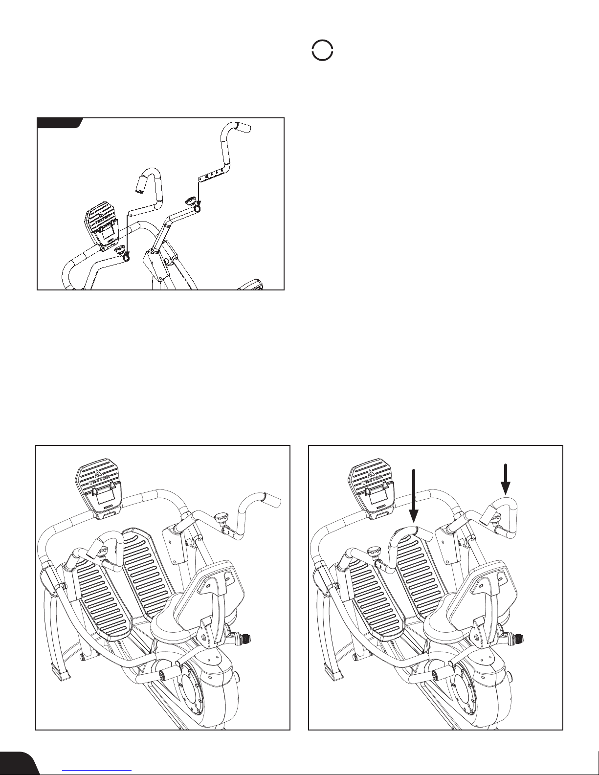
Assemble Handles
FIGURE 21
CORRECT
The Right and Left Handles are
assembled correctly.
Handle Installation
• Loosen the Handle Adjustment Knobs on the right and left
Handle Support Tubes by turning the knobs counter-clockwise,
then pulling outward (Figure 21).
• Locate the Handles, noting Right and Left markings. With the
top of the handles pointing outward, insert both Handles into
the corresponding Handle Support Tube. Adjust Handles as
desired and tighten Handle Adjustment Knobs by releasing into
a hole setting and then rotating clockwise (Figure 21).
INCORRECT
The Right and Left Handles are
switched and need to be corrected.
11
Page 14
User Guide
FIGURE 22
FIGURE 23
Leveling
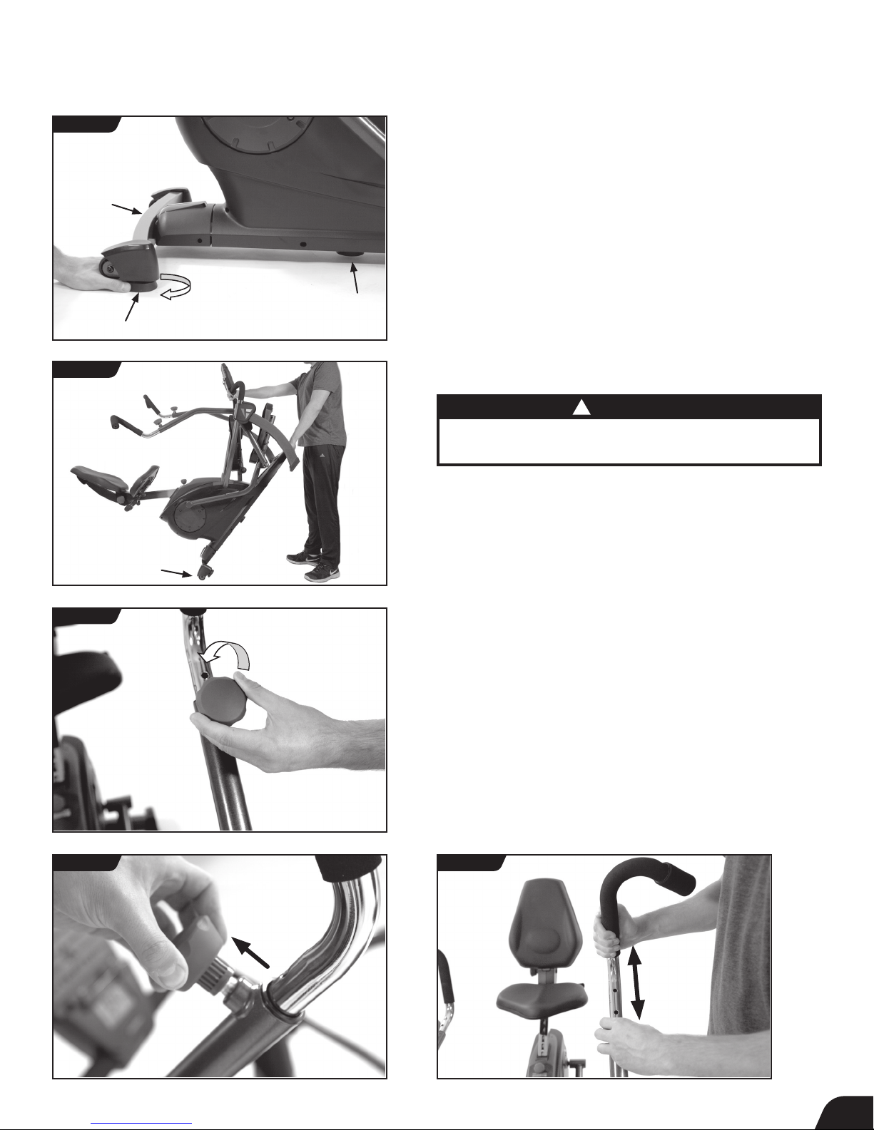
• Make sure your FreeStep™ is on a flat, stable surface. Locate the
3 × Leveling Feet as shown. If any of the feet are not resting flat on
the ground, rotate them clockwise to lower them until they reach
the ground (Figure 22).
Transporting
!
CAUTION
The FreeStep™ weighs 110.0 lb (50.0 kg) and should be lifted
with caution. Lifting heavy objects can cause injury.
• The Transport Wheels are located on the back of the Rear
Stabilizer. To transport, first lift from the Console Front Support
Bar and then from the Front Crossbar. Move the FreeStep
rolling on the Transport Wheels as shown (Figure 23).
™
by
FIGURE 24
Adjust Handles: Height
• Loosen the Handle Adjustment Knob by turning
counter-clockwise (Figure 24).
• The Handle Adjustment Knob is spring loaded, allowing you to
pull the knob outward and then auto-lock it into a hole setting
when released (Figure 25).
• Pull the Handle Adjustment Knob outward while pulling or
pushing on the handle to adjust the height (Figure 26).
• Once both handles are adjusted as desired, turn the Handle
Adjustment Knobs clockwise to secure in place.
FIGURE 25 FIGURE 26
12
Page 15
User Guide
FIGURE 27
FIGURE 28a
OUTWARD SETTING INWARD SETTING INWARD SETTING OUTWARD SETTING
Highest Position Highest Position Lowest PositionLowest Position
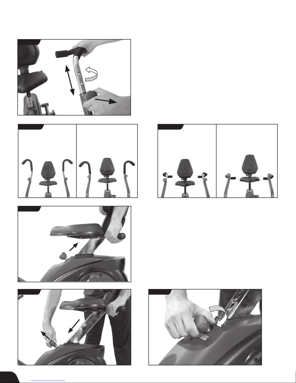
Adjust Handles: Rotation
• To rotate the Handles, loosen the Handle Adjustment Knob and
release by pulling outward. Rotate the Handle and lock the knob
back into place (Figure 27).
• The Handles can be locked into outward and inward settings
with 4 height adjustments each, allowing up to 8 positions total
(Figure 28a and Figure 28b).
FIGURE 28b
FIGURE 29
FIGURE 30 FIGURE 31
Adjust Seat: Height
• To raise the Seat height, simply pull up on the Seat Handle
(Figure 29).
• To lower the Seat height, pull out on the Height Adjustment
Knob and push down on the Seat Handle. Release the Knob in
your desired position, then pull or push on the Handle to ensure
the Seat locks into a hole setting (Figure 30).
• To secure the Seat setting, turn the Height Adjustment Knob
clockwise (Figure 31).
13
Page 16
User Guide
Adjust Seat: Rotation
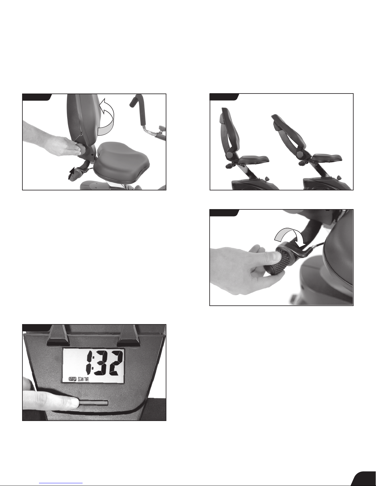
• To recline the Seat, push in on the Seat Back Adjustment Knob
and pull on the Seat Back. Make sure that the Seat Back locks
into a hole setting (Figure 32 and Figure 33).
FIGURE 32
Adjust Resistance
• To increase resistance, rotate the Resistance Adjustment Knob
clockwise, and to decrease resistance, rotate it counter-clockwise
(Figure 34).
FIGURE 33
FIGURE 34
Fully
Upright
Fully
Reclined
FIGURE 35
Using the Console
• When you begin to pedal, the Console will display readings based
on your performance, showing the time in seconds (TMR), calories
burned (CAL), distance in miles (DST), and speed in miles per
hour (SPD) (Figure 35).
• SCAN: While pedaling, the Console will automatically scan
through all the settings. To stop scanning automatically and to
cycle through to the setting you want to see, press the Console
Button. (Figure 35).
• RESET: To start at zero, holding down the Console button will
reset your settings.
• STOP: When you stop pedaling, the STOP will flash until you
begin pedaling again. If you are done with your workout, the
Console will automatically shut off.
14
Page 17
User Guide
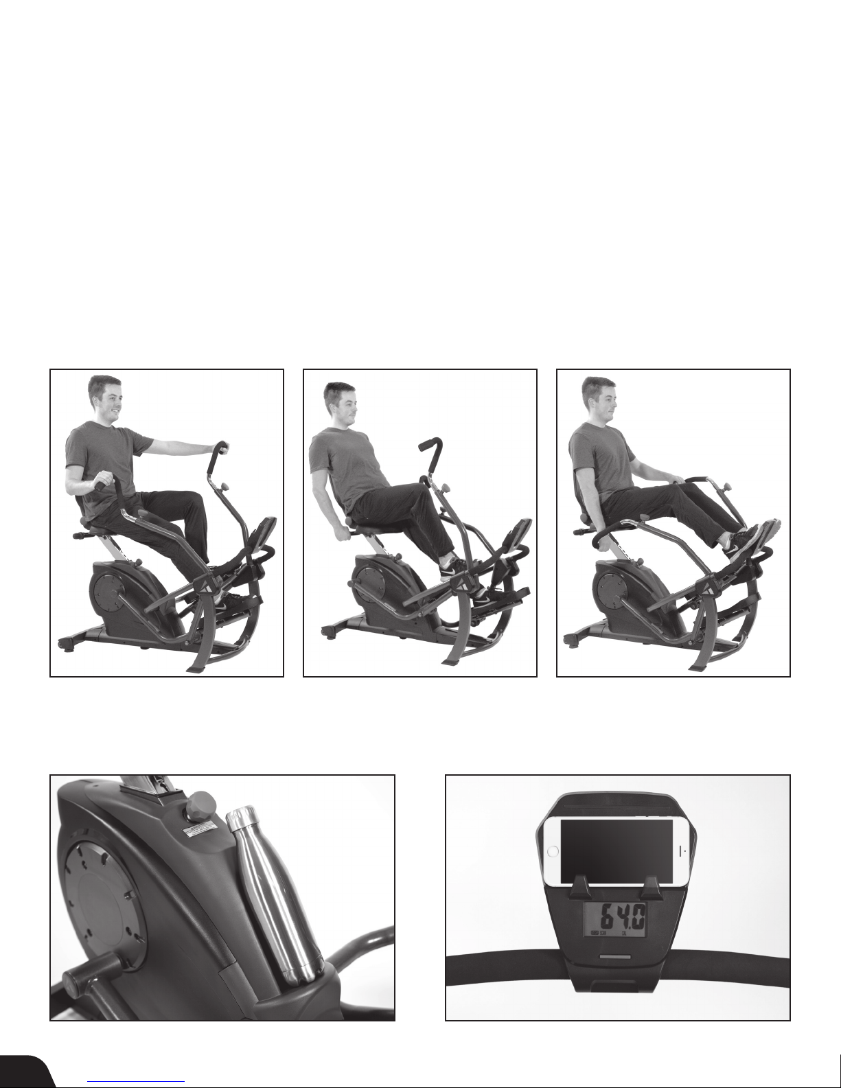
SUGGESTED USE
Standard Use
• For a balanced, full-body workout, use
both your arms and legs to power
the FreeStep
• Adjust the handles to the outward
position. Adjust the Seat Height so your
knees are at a slight angle during the
maximum downward pedal position.
Align the Seat Back to support a straight,
upright posture.
™
.
Legs Only
• Target and tone leg muscles by
powering the FreeStep
your legs.
• Adjust the Seat Height so your knees are
at a slight angle during the maximum
downward pedal position. Align the Seat
Back to a slightly reclined position to
target the glutes and quadriceps. Hold
onto the Seat Handles behind the Seat.
™
with only
Arms Only
• Target and tone arm muscles by
powering the FreeStep
your arms.
• Adjust the handles to the inward position.
Adjust the Seat Height so your knees are
at a slight angle while feet are resting on
the Console Front Support Bar. Align the
Seat Back to support a straight, upright
posture. Target triceps with an overhand
grip as shown, or switch to an underhand
grip to target biceps.
™
with only
Water Bottle Holder Device Holder
15
ADDITIONAL FEATURES
Page 18
WARRANTY & REGISTRATION
The Teeter warranty set forth below and on Teeter’s website applies to US and Canadian customers only.
For international customers, please consult your local distributor for warranty information, which will vary
depending on country.
Teeter warrants this product to be free from defects in workmanship and material, under
A
W
R
D
R
E
A
T
I
M
I
L
N
T
1 YEAR /
90 DAYS
P
A
R
Handling and transportation costs related to product warranty service only are covered by this warranty. This warranty does
not cover damage resulting from improper handling, assembly, or installation, repairs made by others, accident, misuse,
or abuse. Under no circumstances shall Teeter, or any other party involved in the sale of this product, have any liability for
incidental or consequential damage arising from breach of an express or implied warranty on any Teeter product.
EXCEPT AS SET FORTH ABOVE, NO WARRANTY IS GIVEN WITH RESPECT TO ANY TEETER PRODUCT, AND ALL EXPRESS
WARRANTIES ARE DISCLAIMED. To the extent this warranty is found not to be enforceable, it shall be deemed revised
to the extent necessary to make it enforceable. This warranty and any controversy or claim arising out of this warranty or
its interpretation shall be governed by the laws of the State of Washington, USA. Any controversy or claim arising out of or
relating to this warranty, its interpretation, or any alleged breach thereof, which cannot be amicably settled between Teeter
and the owner within sixty (60) days of written notice by the aggrieved party to the other, shall be nally settled by arbitration
submitted to three (3) arbitrators selected from the panels of the arbitrators of the American Arbitration Association located
closest to Teeter’s principal place of business.
O
B
T
S
A
L
&
normal use and service conditions, during the period starting with the day of retail purchase and
continuing for: ninety (90) days for the base of the product (including the drive mechanism and all
Y
moving parts therein) and one (1) year for the rest of the product (excluding the base), including
any defects in materials, workmanship, fabrics and padding. If a repair or replacement is not
R
commercially practical or cannot timely be made, then Teeter will, at the original Purchaser’s
option, replace the product or the applicable portion of the product with a comparable product or
refund the purchase price.
Some states do not allow the exclusion of incidental or consequential damage from a warranty, so the above limitation or
exclusion may not apply to you. Some states do not allow limitations on how long an implied warranty lasts, so the above
limitation may not apply to you. This warranty gives you specic legal rights, and you may also have other rights which may
vary from state to state. This warranty is completely transferable to any and all future owners of this product, provided no
alterations have been made to the product.
HOW TO SUBMIT YOUR REGISTRATION:
Step 1
Fill out this information for your own records.
Step 2
Go online to teeter.com to register your warranty.
Date of Purchase
Product & Model
Dealer Name
Serial No.
If you are unable to go online, you can request a warranty card to be mailed to you by calling Customer Service at 800-847-0143.
Please DO NOT mail this to Teeter.
16
Page 19

Find These Great Products and More at teeter.com!
EP-970™ Inversion Table
The premier Teeter Inversion Table
featuring the Deluxe EZ-Reach
Handle to reduce the need for
bending, Traction Handles to enhance
decompression at lesser angles
and Stretch Max Handles for added
support and stretching options.
Sit-Stand™ Desk
Sit, stand and keep moving during
your workday to boost productivity,
comfort and good posture habits.
Core Restore
Soothe your tired, aching back with
this multi-functional lumbar support
and core training tool designed to
help relieve back pain and strengthen
supporting muscles.
T3™ Massager
Countless options for self-massage,
trigger point therapy, and myofascial
release to resolve tension and pain gently
and naturally.
Roger Teeter
Founder & Innovator
USA: Teeter
9713 233rd Avenue East
Bonney Lake, WA 98391
Toll Free: 800-847-0143
Fax: 800-847-0188
teeter.com | [email protected]
U.S. and Foreign Patents Apply. Teeter and Teeter logo are registered trademarks of Teeter. Specications subject to change without notice.
© COPYRIGHT 2017 Teeter. International Law Prohibits Any Copying. SE1040 1117-0
If you have any trouble assembling the equipment, or questions
about its use, please contact customer service.
Check out the selection of products and accessories
available at teeter.com!
International: Teeter International, Ltd.
Gor-Ray House
758 Great Cambridge Rd
Eneld
Middlesex EN1 3GN
United Kingdom
teeterintl.com | [email protected]
 Loading...