

TeemLosi XXX-4 Graphite Plus Owner's Manual

OWNER'S
MANUAL
Carefully read through all instructions to familiarize yourself with the parts, construction techniques, and
tuning tips outlined in this manual. Being able to grasp the overall design of your new XXX-4 Graphite
Plus Buggy before beginning the construction process will ensure a smooth assembly.
Take your time and pay close attention to detail. Keep this manual for future reference.
Team losi, Division of Horizon Hobby inc.,
4710 Gausti Rd., Ontario CA 91761
Phone: (909) 390-9595 / Fax: (909) 390-5356
www.TeamLosi.com / feedback@TeamLosi.com
MADE IN THE UNITED STATES OF AMERICA
P/N 800-0208
10/01/2003
JAC/RWW
Welcome Team Losi XXX-4 Owner!
Thank you for selecting Team Losi and the XXX-4 Graphite Plus as your new racing buggy. As you will see, we have
made every effort to design and produce a kit that is not only the most competitve, but easy to build and maintain. The simple
bag-by-bag assembly sequence and unmatched easy to follow instructions, combined with Team Losi's world famous qualityfitting parts, should make building your new XXX-4 Graphite Plus a most enjoyable project.
Before you open the first bag or start any assembly, please take a few moments to read completely through the following
instructions. This will familiarize you with the various parts as well as the tools you will need. Taking an extra moment before
starting can save you a good deal of time and assure proper assembly.
Once again, thank you for choosing Team Losi.
Good luck and good racing!
1. INTRODUCTION
XXX-4 GRAPHITE PLUS COMPLETED KIT DIMENSIONS
Overall Length: 15-3/8" Front Width: 9-3/4" Rear Width: 9-5/8" Height: 5-3/8"
Wheelbase: 10-3/4" All dimensions at ride height. Weight will vary depending on accessories.
NOTES & SYMBOLS USED
Step A-1
This is a common Step sequence found at the beginning of each
new illustration throughout the manual.
q 1. Each step throughout the entire manual has a check box to the
left of it. As you complete each step, mark the box with a check. If you
need to take a break and return to building at a later time you will be
able to locate the exact step where you left off.
This is a common note. It is used to call attention to specific
details of a certain step in the assembly.
IMPORTANT NOTE: Even if you are familiar with Team
Losi kits, be sure and pay attention to these notes. They point out
very important details during the assembly process. Do not ignore
these notes!
In illustrations where it is important to note which
direction parts are facing, a helmet like this one will be included in the
illustration. The helmet will always face forward in the car as the
driver would. Any reference to the right or left side will relate to the
direction of the helmet.
KIT/MANUAL ORGANIZATION
The kit is composed of different bags marked A through H. Each
bag contains all of the parts necessary to complete a particular sec-
tion of the XXX-4 Graphite Plus. Some of these bags have subas-
sembly bags within them. It is essential that you open only one bag
at a time and follow the correct assembly sequence, otherwise you
may face difficulties in finding the correct part. It is helpful to read
through the instructions for an entire bag prior to beginning assembly. Key numbers (in parenthesis) have been assigned to each part
and remain the same thoughout the manual. In some illustrations,
parts which have already been installed are not shown so that the
current steps can be illustrated more clearly.
For your convenience, an actual-size hardware identification
guide is included with each step. To check a part, hold it against the
silhouette until the correct part is identified. In some cases extra
hardware has been supplied for parts that may be easy to lose.
The molded parts in the XXX-4 Graphite Plus are manufactured
so that they interlock. When screws are tightened to the point of
being snug, the parts are held firmly in place. For this reason it is
very important that screws not be overtightened in any of the plastic
parts.
To ensure that parts are not lost during construction, it is recommended that you work over a towel or mat to prevent parts from
rolling away.
IMPORTANT SAFETY NOTES
1. Select an area for assembly that is away from the reach of small
children. Some parts in this kit are small and can be swallowed by
children, causing choking and possible internal injury.
2. The shock fluid and greases supplied should be kept out of
childrens' reach. They are not intended for human consumption!
3. Exercise care when using any hand tools, sharp instruments,
or power tools during construction.
4. Carefully read all manufacturer's warnings and cautions for
any glues, chemicals, or paints that may be used for assembly and
operating purposes. When you are using glues, chemicals, and paints
you should always wear eye protection and a mask.
i

TOOLS REQUIRED
Team Losi has supplied all necessary Allen Wrenches and two special assembly wrenches that are needed for slipper adjustment, assembly and
Tierod adjustments. The following common tools will also be required: Needle-nose pliers, regular pliers, medium grit sandpapper, hobby knife,
scissors, and body cutting/trimming tools. A soldering iron may be necessary for electrical installation. 3/16", 1/4", and 11/32" nut drivers are
optional.
RADIO/ELECTRICAL
A suggested radio layout is provided in this manual. Your high-performance R/C center should be consulted regarding specific questions
pertaining to radio/electrical equipment.
HARDWARE IDENTIFICATION
When in question, use the hardware identification guide in each step. For screws, the prefix number designates the screw size and number of
threads per inch (i.e. 4-40 is #4 screw with 40 threads per inch). The second number or fraction, designates the length of the screw. For cap head
and button head screws, this number refers to the length of the threaded portion of the screw. For flat head screws, this number refers to the
overall length of the screw. Bearings and bushings are referenced by the (inside diameter) x (outside diameter) (ie. 3/16 x 3/8). Shafts and pins
are referred to by diameter x length. Washers are described by inside diameter or the screw size that will pass through the inside diameter. E-clips
are sized by the shaft diameter that they attach to.
MOTORS AND GEARING
The XXX-4 G+ includes an 92-tooth, 48-pitch spur gear. The internal drive ratio of the XXX-4 G+ is 2.10. The pinion gear that is used will
determine the final drive ratio. To calculate the final drive ratio, first divide the spur gear size by the pinion gear size. For example, if you are using
a 20-tooth pinion gear, you would divide 92 (spur gear size) by 20 (pinion gear size). 92/20 = 4.60. This tells you that 4.60 is the external drive ratio.
Next, multiply the internal drive ratio (2.10) by the external drive ratio (in this case 4.60). 2.10 x 4.60 = 9.66:1. This means that by using a 20-tooth
pinion gear with the standard 92-tooth spur gear, the final drive ratio is 9.66:1.
Consult you high-performance shop for recommendations to suit your racing style and class. The chart below lists some of the more
common motor types and recommended initial gearing for that motor. Ratios can be adjusted depending on the various track layouts, tire sizes,
and battery types.
RECOMMENDED INITIAL GEARING FOR COMMON MOTORS
TYPE OF MOTOR PINION SPUR
24º (Depending on motor and track size) 17-20 92
8-Turn Modified 16 92
9-Turn Modified 17 92
10-Turn Modified 18 92
11-Turn Modified 19 92
12-Turn Modified 20 92
13-Turn Modified 21 92
14-Turn Modified 22 92
15-Turn Modified 23 92
TABLE OF CONTENTS
1. INTRODUCTION ................................................................................ i
Completed Kit Dimensions .............................................................. i
Notes & Symbols .............................................................................. i
Kit/Manual Organization ................................................................. i
Important Safety Notes .................................................................... i
Tools Required ................................................................................. ii
Radio/Electrical ................................................................................ ii
Hardware Identification .................................................................. ii
Motors and Gearing ........................................................................ ii
2. BAG A ............................................................................................... 1-7
3. BAG B ...............................................................................................8-11
4. BAG C ..........................................................................................12-15
5. BAG D ........................................................................................ 16-20
6. BAG E ......................................................................................... 21-25
7. BAG F ......................................................................................... 26-28
8. BAG G ................................................................................................ 29
9. BAG H ........................................................................................ 30-34
10. Checklist Before Your First Run ................................................ 35
11. Tips From the Team .................................................................. 35-37
12. Spare Parts List ........................................................................ 38-41
Team Losi is continually changing and improving designs; therefore, the actual part may appear slightly different than the illustrated part. Illustrations of parts and
assemblies may be slightly distorted to enhance pertinent details.
ii
BAG A
19
108
CLEAR DIFF
GREASE (172)
STOP! There are two, complete Differential assemblies in the XXX-4 G+ kit. The Front - Plastic Differential, shown in steps A1 thru A-9 and The Rear - Steel Differential, shown in steps A-10 thru A-19. The XXX-4 G+ kit was designed using the stock 42T
Drive Pulleys in the front and rear of the car. There is an optional 41T Pulley included in Bag H of this kit, this feature can be used
to apply under-drive or over-drive in the vehicle. See "Final Checklist" at the end of this manual.
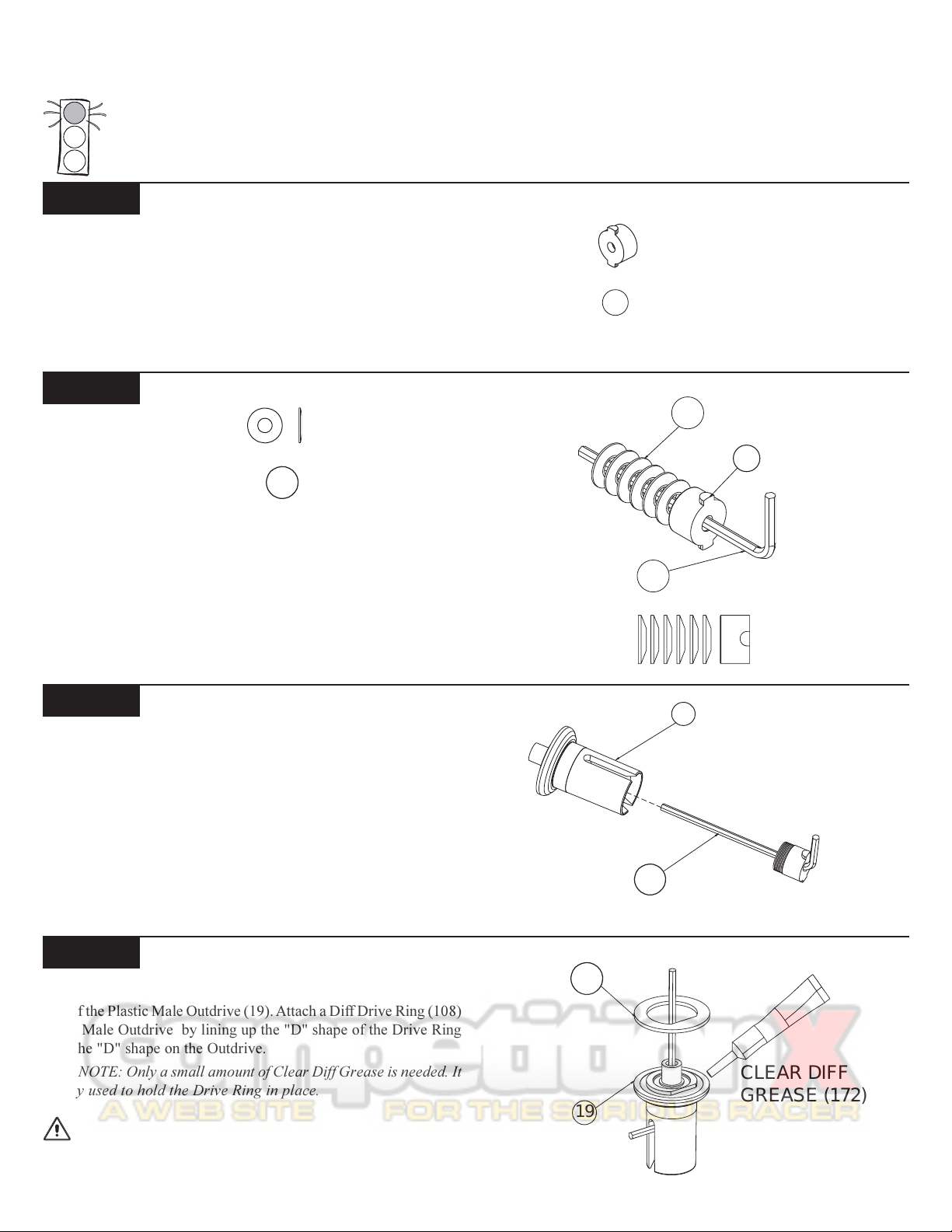
Step A-1
Diff Nut Carrier:
q 1. Locate the Diff Nut (27).
Step A-2
Diff Nut With Belleville Washers:
154
q 1. Locate the 1/16" Allen Wrench (125) supplied with the kit.
Place the Diff Nut (27), "T" side first, over the Allen Wrench towards
the "L"end.
q 2. Stack the six 1/8" Belleville Washers (154) over the Wrench
and up against the Diff Nut. The Washers should all point the same
direction and open away from the Diff Nut as shown in Figure 2B.
Figure 1
27
154
27
Figure 2A
125
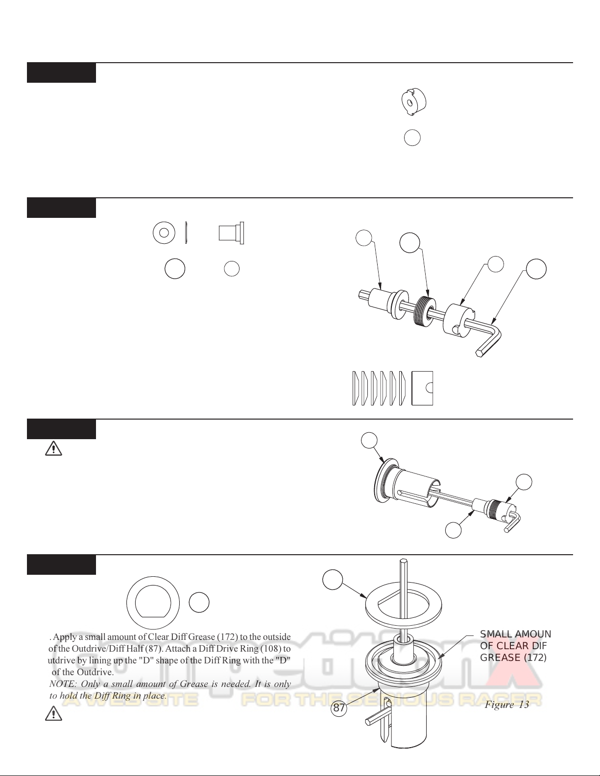
Step A-3
Diff Nut to Male Outdrive:
q 1. Insert all of the parts that are stacked on the Wrench (125) into
the Plastic Male Outdrive/Diff Half (19) (the one with the post). Line
up the tabs on the Diff Nut (27) with the slots in the Male Outdrive.
Press the parts all the way into the Male Outdrive.
Step A-4
Diff Drive Ring to Male Outdrive:
q 1. Apply a small amount of Clear Diff Grease (172) to the outside
ring of the Plastic Male Outdrive (19). Attach a Diff Drive Ring (108)
to the Male Outdrive by lining up the "D" shape of the Drive Ring
with the "D" shape on the Outdrive.
*NOTE: Only a small amount of Clear Diff Grease is needed. It
is only used to hold the Drive Ring in place.
Figure 2B
19
125
Figure 3
IMPORTANT NOTE: Do not glue the Drive Rings to the
Outdrive/Diff Halves. Doing so may not allow the Rings to mount flat
on the Outdrive.
Figure 4
1
BAG A (Continued)
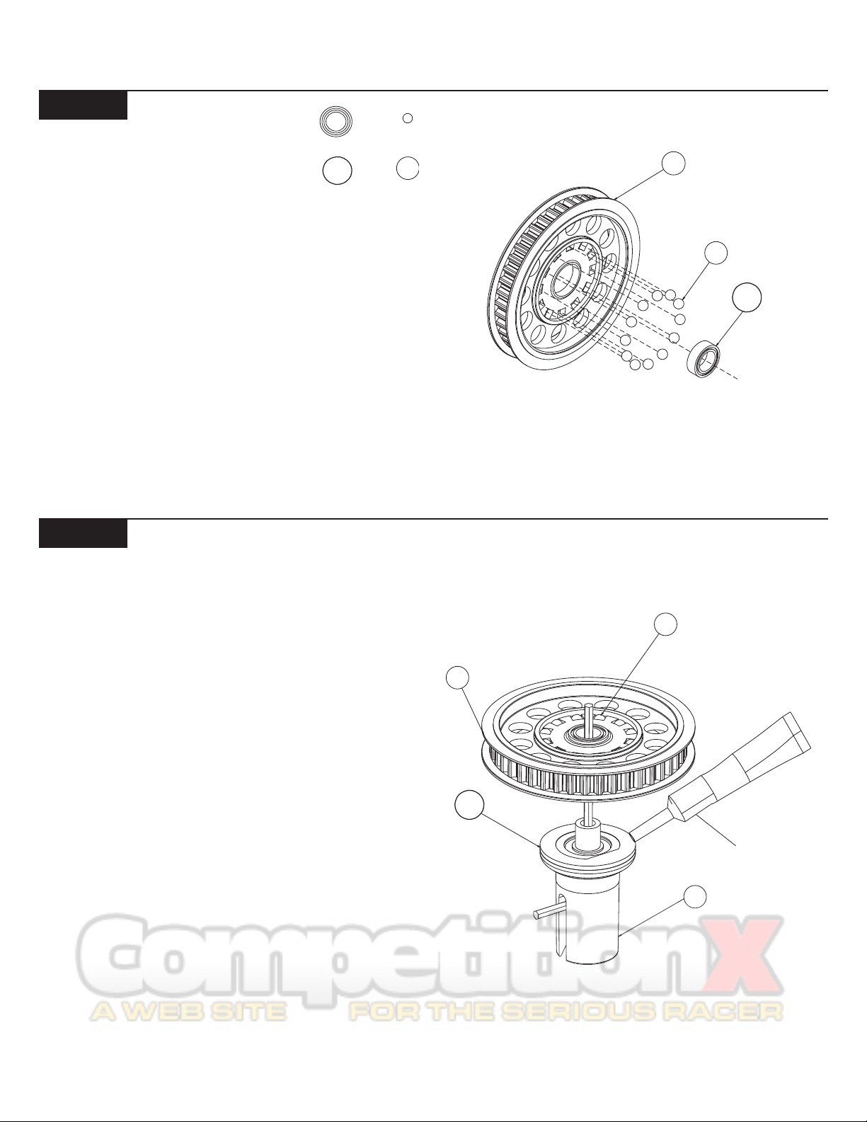
Step A-5
Diff Pulley:
117
82
q 1. Insert a 5mm x 8mm Bearing (117) into the center of the 42T Diff
Pulley (42).
q 2. Press a 3/32" Diff Ball (82) into each of the twelve small holes
in the Diff Pulley as indicated in Figure 5.
42
82
117
Figure 5
Step A-6
Diff Pulley to Male Outdrive:
q 1. Apply a moderate coat (continuous bead) of Clear Diff Grease
(172) to the exposed side of the Diff Ring (108) that is already attached to the Male Outdrive (19).
q 2. Carefully place the Diff Pulley (42) over the post on the
Outdrive so that the Diff Balls (82) and Diff Pulley rest against the
Greased Drive Ring. Leave the assembly with the 1/16" Allen Wrench
(125) standing as shown in Figure 6.
42
108
82
Figure 6
CLEAR DIFF
GREASE (172)
19
2
BAG A (Continued)
F
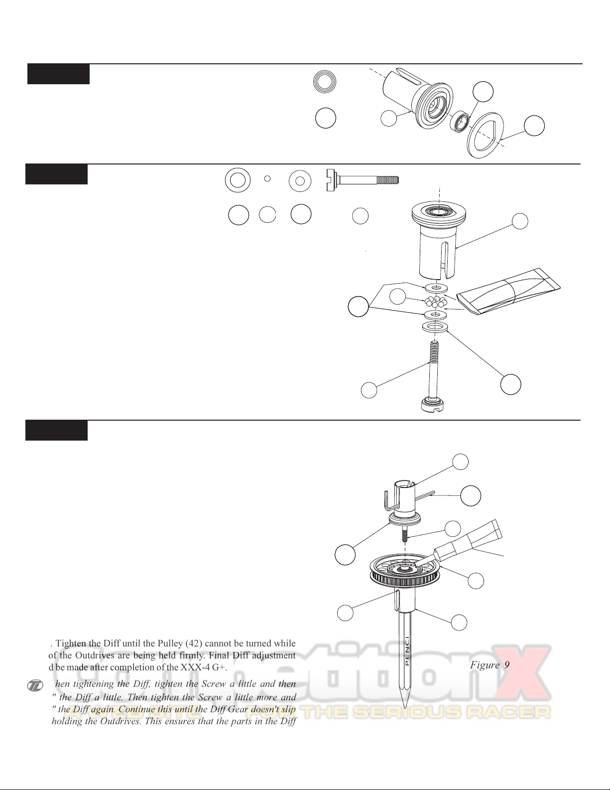
Step A-7
Bearing to Female Outdrive:
q 1. Press a 5mm x 8mm Bearing (117) into the center area of the
Female Plastic Outdrive/Diff Half (20) as indicated. The edge of the
Bearing should be flush with the front of the Outdrive.
q 2. Apply a small amount of Clear Diff Grease (172) to the outer
ring of the Outdrive. Install the second Drive Ring (108), again aligning the "D" shape of the Outdrive and the Drive Ring.
Step A-8
Female
Outdrive Assembly:
186
q 1. Place the foam Thrust Bearing Seal (186) over the shoulder of
the Diff Adjusting Screw (91).
q 2. Place one of the 3mm x 8mm Thrust Bearing Washers (149)
over the Diff Screw.
q 3. Using the MIP RED Grease (157), apply a fairly heavy coat of
Grease to the Thrust Washer and position the eight 5/64" Thrust
Balls (95) in a circular pattern around the Diff Screw. Apply another
coat of RED MIP Grease over the Thrust Balls and place the second
Thrust Bearing Washer over the Diff Screw and up against the Thrust
Balls.
q 4. Insert the Diff Screw into the Female Outdrive (20). Pull the
threaded end of the Diff Screw until the Thrust assembly rests against
the inside of the Outdrive.
95
149
117
Figure 7
91
149
Figure 8
91
117
20
108
20
95
MIP RED
GREASE
(157)
186
Step A-9
Male to Female Outdrive Assembly:
q 1. Carefully replace the Allen Wrench (125) from the Male Outdrive
(19) with a pen or pencil, and place it in the slot of the Female Outdrive
(20) containing the Diff Screw (91). The pen will be used to hold the
Diff Nut (27) assembly in the bottom side.
q 2. Apply a good amount of Clear Diff Grease (172) (enouth to
cover the Balls completely) to the exposed side of the Balls in the Diff
Pulley (42) on the Male Outdrive.
q 3. While holding the Female Outdrive with Allen Wrench inserted,
carefully assemble it to the Male Outdrive.
q 4. Make sure that the slot in the Diff Screw is lined up with the
slot in the Female Half and then while holding the Male Half slowly
turn the Female Outdrive until the threads of the Diff Screw engage
on the threads of the Diff Nut. Remove the pencil from the Male Half
and thread the two Outdrives together until the Screw just starts to
snug up.
q 5. Tighten the Diff until the Pulley (42) cannot be turned while
both of the Outdrives are being held firmly. Final Diff adjustment
should be made after completion of the XXX-4 G+.
When tightening the Diff, tighten the Screw a little and then
"work" the Diff a little. Then tighten the Screw a little more and
"work" the Diff again. Continue this until the Diff Gear doesn't slip
while holding the Outdrives. This ensures that the parts in the Diff
are properly seated. Refer to Tech Tips for final adjustment. "Working" the Diff is done by rotating the Outdrives in opposite directions.
20
125
91
108
27
19
PENCIL
3
CLEAR DIF
GREASE
42
Figure 9
(172)
BAG A (Continued)
Step A-10
Diff Nut Carrier:
q Locate the Diff Nut (27).
Step A-11
Diff Tube Assembly:
154
86
q 1. Locate the 1/16" Allen Wrench (125) supplied with the kit.
Place the Diff Nut (27), "T" side first, over the Allen Wrench towards
the "L-end."
q 2. Stack the six 1/8" Belleville Washers (154) over the Wrench
and up against the Diff Nut. The Washers should all point the same
direction and open away from the Diff Nut as shown in Figure 11B.
86
27
Figure 10
154
Figure 11A
27
125
q 3. Place the Diff Tube (86) over the Wrench, large side first, so
that it rests against the Belleville Washers as shown in Figure 11A.
Step A-12
IMPORTANT NOTE: Male Outdrive defined as: Outdrive
containing Diff Tube assembly (Figure 11A). Female Outdrive defined as: Outdrive containing Thrust assembly (Figure 17).
Diff Tube Assembly to Outdrive:
q 1. Insert all of the parts that are stacked on the Wrench (125) into
the steel Outdrive/Diff Half (87). Line up the tabs on the Diff Nut (27)
with the slots in the Outdrive. Press the parts all the way into the
Outdrive, so that the Diff Tube (86) is seated inside the Outdrive.
Step A-13
Diff Drive Ring to Male Outdrive:
108
q 1. Apply a small amount of Clear Diff Grease (172) to the outside
ridge of the Outdrive/Diff Half (87). Attach a Diff Drive Ring (108) to
the Outdrive by lining up the "D" shape of the Diff Ring with the "D"
shape of the Outdrive.
*NOTE: Only a small amount of Grease is needed. It is only
there to hold the Diff Ring in place.
IMPORTANT NOTE: Do not glue the Diff Ring to the
Outdrive/Diff Halves. Doing so may not allow the Rings to mount flat
on the Outdrive.
Figure 11B
87
27
Figure 12
108
87
4
86
SMALL AMOUNT
OF CLEAR DIFF
GREASE (172)
Figure 13
BAG A (Continued)
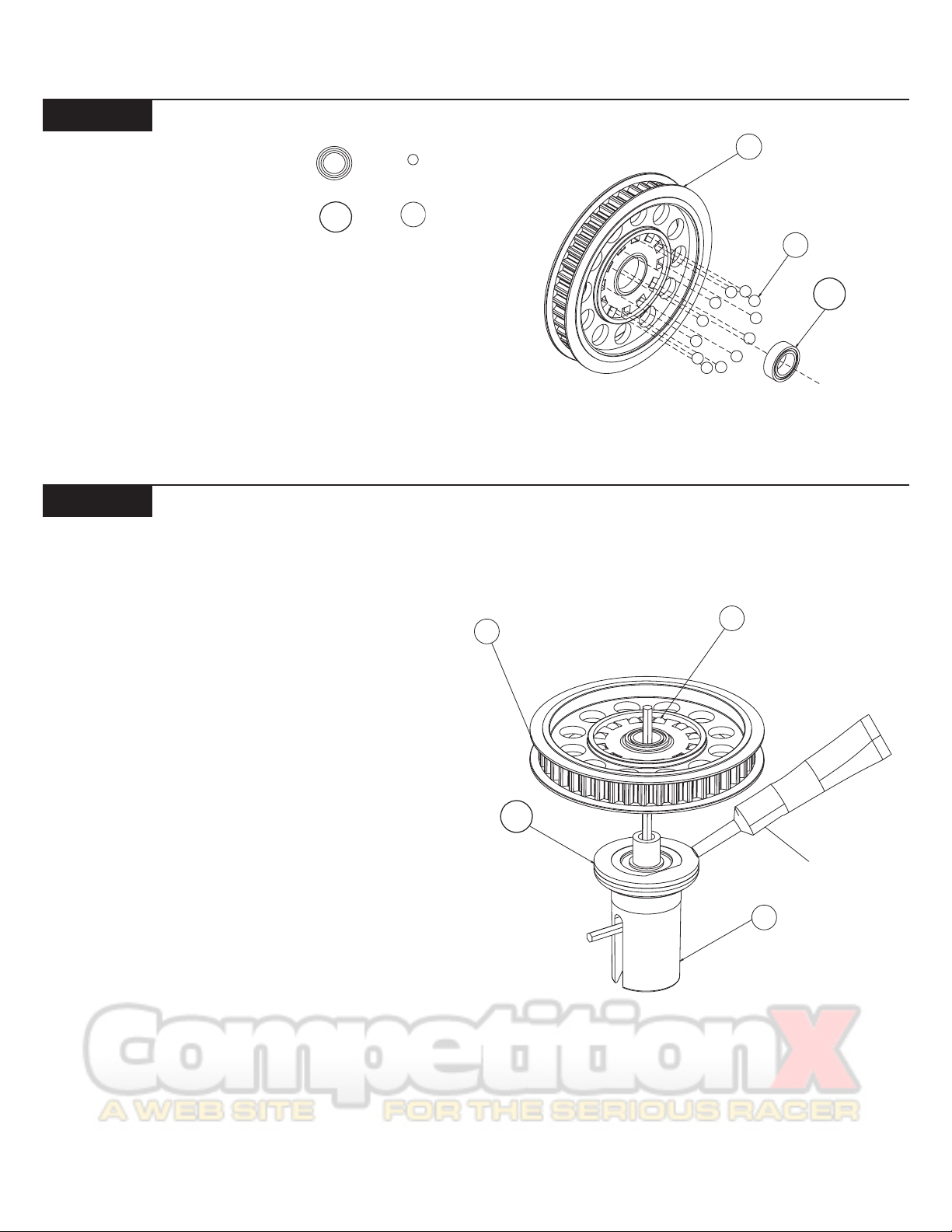
Step A-14
Diff Pulley:
117
82
q 1. Insert a 5mm x 8mm Bearing (117) into the center of the 42T Diff
Pulley (42).
q 2. Press a 3/32" Diff Ball (82) into each of the small holes in the
Diff Pulley as indicated in Figure 14.
Step A-15
Diff Pulley to Diff Tube:
42
82
117
Figure 14
q 1. Apply a moderate coat (continuous bead, same as step A-9) of
Clear Diff Grease (172) to the exposed side of the Diff Ring (108) that
is already attached to the Male Outdrive (87).
q 2. Carefully place the Diff Pulley (42) over the post on the
Outdrive so that the Diff Balls (82) and Diff Pulley rest against the
Greased Diff Ring. Leave the assembly with the 1/16" Allen Wrench
(125) standing as shown in Figure 15.
42
82
Figure 15
108
CLEAR DIFF
GREASE (172)
87
FIGGIGUREFASDF
5
BAG A (Continued)
Step A-16
Female Outdrive Bearing Install:
153
117
q 1. Insert a 5mm x 8mm Bearing (117) into the second Outdrive/
Diff Half (87). Make sure that the Bearing is pushed all the way into
the Outdrive. A pencil or the handle of a hobby knife can be used to
push the Bearing into place.
q 2. Apply a slight amount of Clear Diff Grease (172) to the
1/4" x 5/16" Shim (153). Insert the Shim into the Outdrive/Diff Half
next to the 5mm x 8mm Bearing. Make sure that the Shim is flat against
the Bearing. Be extra careful not to bend this Shim!
*NOTE: Only a small amount of Grease is needed. It is only
needed to hold the Shim in place next to the Bearing.
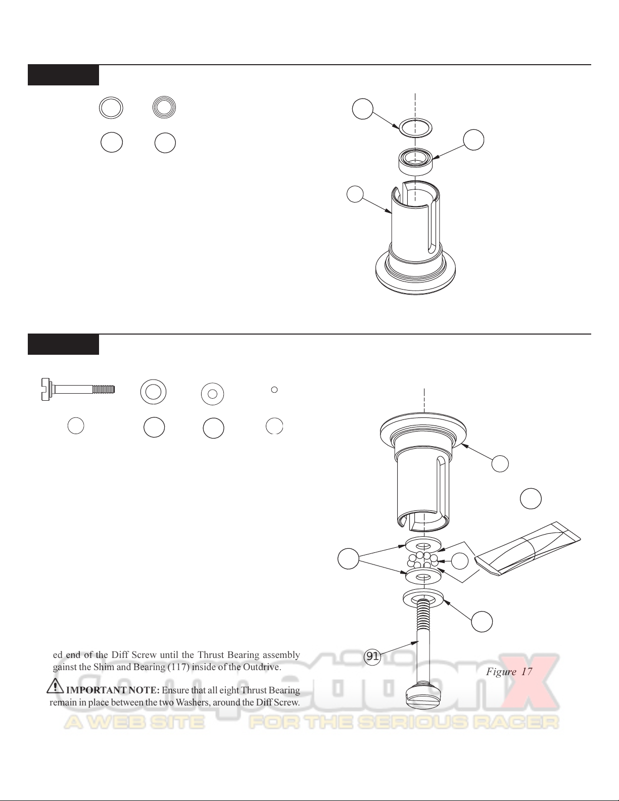
Step A-17
Diff Adjusting Screw Assembly:
153
117
87
Figure 16
91
186
149
95
q 1. Locate the Diff Adjusting Screw (91) and place the Foam Thrust
Bearing Seal (186) over the shoulder of the Screw.
q 2. Place one of the 3mm x 8mm Thrust Bearing Washers (149)
over the Diff Screw.
*NOTE: The Thrust Bearing Washers are packaged in a small
bag along with the eight 5/64" Thrust Bearing Balls.
q 3. Grease the Thrust Washer well with MIP RED Thrust Bearing
Grease (157) and place the eight 5/64" Thrust Bearing Balls (95) on
top of the Washer, around the Diff Screw. Apply more RED Thrust
Bearing Grease to the tops of the Thrust Bearing Balls. Place the
second Thrust Washer over the Screw and against the Thrust Bearing Balls.
q 4. Very carefully insert the Diff Screw, with the Thrust Bearing
assembly installed, into the Female Outdrive (87). Be very careful not
to bend or pinch the Shim (153) while inserting the Diff Screw. Pull the
threaded end of the Diff Screw until the Thrust Bearing assembly
rests against the Shim and Bearing (117) inside of the Outdrive.
IMPORTANT NOTE: Ensure that all eight Thrust Bearing
Balls remain in place between the two Washers, around the Diff Screw.
149
91
87
MIP RED
THRUST BEARING
GREASE
95
186
Figure 17
157
6
BAG A (Continued)
F
Step A-18
Diff Drive Ring to Female Outdrive:
108
q 1. Locate the smallest of the Allen Wrenches, 0.050 (128), and
place it through the slot in the Outdrive/Diff Half (87) containing the
Diff Screw (91). Slide the Wrench all the way against the Screw. By
handling the Outdrive/Diff Half with the Wrench inserted, the Diff
Screw will be held in place while finishing the assembly of the Differential.
q 2. Apply a small amount of Clear Diff Grease (172) to the outer
ridge of the Outdrive. Install the remaining Diff Ring (108), again
lining up the "D" shape of the Outdrive/Diff Half with the "D" shape
of the Ring.
IMPORTANT NOTE: Do not glue the Diff Rings to the
Outdrive/Diff Halves. Doing so may not allow the Rings to mount flat
on the Outdrive.
91
87
108
SMALL AMOUNT
OF CLEAR DIFF
GREASE (172)
128
Figure 18
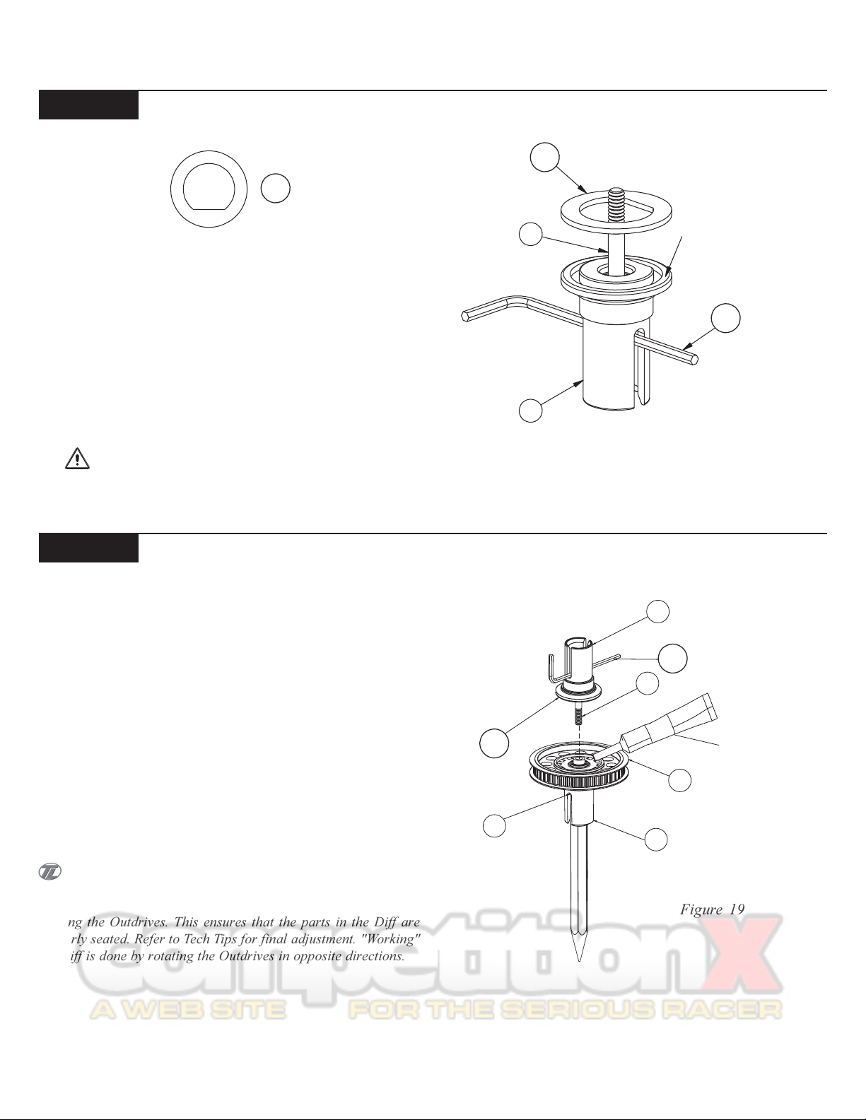
Step A-19
Outdrive Assembly:
q 1. Carefully replace the Allen Wrench (125) with a pen or pencil
from the Male Outdrive (87). The pen will be used to hold the Diff Nut
(27) assembly in the bottom side.
q 2. Apply a fairly heavy coat of Clear Diff Grease (172) to the
exposed side of the Diff Ring (108) on the Female Outdrive.
q 3. While holding the Female Outdrive with Allen Wrench inserted,
carefully assemble it to the Male Outdrive.
q 4. Make sure that the slot in the Diff Screw is lined up with the
slot in the Female Half and then while holding the Male Half, slowly
turn the Female Outdrive until the threads of the Diff Screw engage
on the threads of the Diff Nut (27). Remove the pencil from the Male
Half and thread the two Outdrives together until the Screw just starts
to snug up.
q 5. Tighten the Diff until the Pulley (42) cannot be turned while
both of the Outdrives are being held firmly. Final Diff adjustment
should be made after completion of the XXX-4 G+.
When tightening the Diff, tighten the Screw a little and then
"work" the Diff a little. Then tighten the Screw a little more and
"work" the Diff again. Continue this until the Diff doesn't slip while
holding the Outdrives. This ensures that the parts in the Diff are
properly seated. Refer to Tech Tips for final adjustment. "Working"
the Diff is done by rotating the Outdrives in opposite directions.
108
27
PENCIL
87
91
87
128
42
Figure 19
CLEAR DIF
GREASE
(172)
7
BAG B
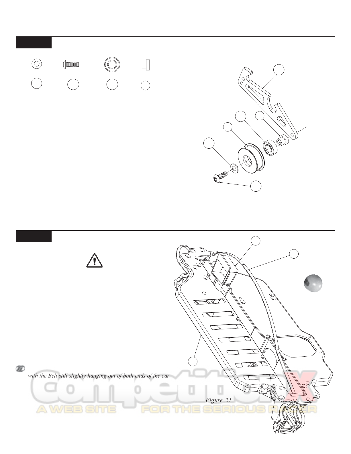
Step B-1
152
Tensioner Arm Assembly:
146
116
98
q 1. Snap a 3/16" x 3/8" Bearing (116) into the right side of the Idler
Pulley (44). The Bearing will snap past the ridge and stop.
q 2. Place the Idler Pulley Shaft (98) through the Idler Pulley from
the Bearing side.
q 3. Slide a #4 x .020 Washer (152) over the 4-40 x 5/16" Button
Head Screw (146).
q 4. Insert the 4-40 x 5/16" Button Head Screw through the Idler
Pulley and thread it into the Belt Tensioner Arm (110) positioned as
shown in Figure 20.
152
44
116
Figure 20
110
98
146
Step B-2
NEVER OVER TIGHTEN THE SCREWS IN THE
CHASSIS - Team Losi has designed interlocking
features into the XXX-4 G+ Chassis. Only tighten the
Screws to the point of being snug, so the parts are held
Belt Installation:
*NEVER PINCH THE BELT*
firmly in place.
q 1. Position the Chassis (46) upside-down on your work bench.
Insert the Belt (77) and pull it through both ends of the Chassis.
q 2. Pull the Belt out, just slightly, through the bottom of the Chas-
sis and insert the Steering Tunnel (29), tall end forward, into the slot
in the front of the Chassis. Press into position as indicated in Figure
21.
The Steering Tunnel should now be located in between the
Belt, with the Belt still slightly hanging out of both ends of the car.
29
77
46
Figure 21
8
BAG B (Continued)
20
42
62
129
77
46
134
SIDE WITH
DIFF NUT (27)
118
19
Step B-3
Front Diff
Install:
118
134
Note:Use the Plastic Diff assembly for the Front of the
XXX-4 G+.
There is a short Thread-Cutting Screw included in the Wrench
bag. This Screw can be used to tap threads in the holes in the Main
Chassis and the bottom of the Diff Covers. Pre-tapping these holes
makes it easier to install the Screws during assembly.
q 1. Slide one 1/2" x 3/4" Bearing (118) over each of the Outdrive
Cups (19),(20) with the teflon seal facing away from the Diff Pulley
(42).
q 2. Pull the Belt (77) slightly out through the front of the Chassis
(46) and install a Diff assembly into the slots as indicated in Figure 22.
Pull the slack from the Belt through the rear of the Chassis.
The head of the Diff Adjustment Screw should always be on
the drivers left side of the Chassis.
q 3. Secure the Diff assembly by installing the front Diff Cover (62)
with two 4-40 x 1/2" Cap Head Screws (129) through the Diff Cover
into the two counter-bored holes in the Chassis.
q 4. Flip the Chassis over and install the two 4-40 x 3/8" Flat Head
Screws (134) through the bottom of the Chassis into the front Diff
cover as indicated in Figure 22.
129
Figure 22
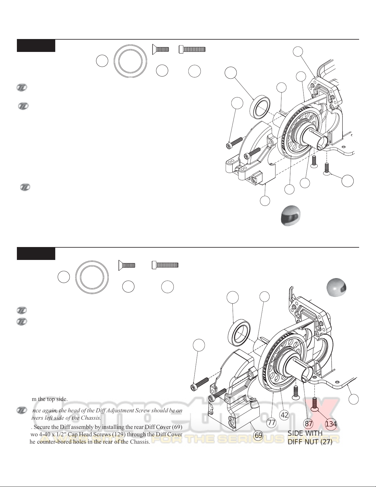
Step B-4
Note: Use the Steel Diff assembly for the rear of the XXX-4 G+.
There is a short Thread-Cutting Screw included in the Wrench
bag. This Screw can be used to tap threads in the holes in the Main
Chassis and the bottom of the Diff Covers. Pre-tapping these holes
makes it easier to install the Screws during assembly.
q 1. Slide one 1/2" x 3/4" Bearing (118) over each of the Outdrive
Cups (87),(87) with the Teflon Seal facing away from the Diff Pulley
(42) on the remaining Differential.
Rear Diff Install:
118
134
q 2. Spread the Belt (77) apart and install the Diff assembly into the
slots of the Chassis (46) as indicated in Figure 23. Once the Diff
assembly is in place, pull the slack up through the center of the Chassis from the top side.
Once again, the head of the Diff Adjustment Screw should be on
the drivers left side of the Chassis.
q 3. Secure the Diff assembly by installing the rear Diff Cover (69)
with two 4-40 x 1/2" Cap Head Screws (129) through the Diff Cover
into the counter-bored holes in the rear of the Chassis.
q 4. Flip the Chassis over and install the two 4-40 x 3/8" Flat Head
Screws (134) through the bottom of the Chassis into the rear Diff
Cover as indicated in Figure 23.
129
118
87
129
46
42
77
69
87
SIDE WITH
134
DIFF NUT (27)
Figure 23
9
BAG B (Continued)
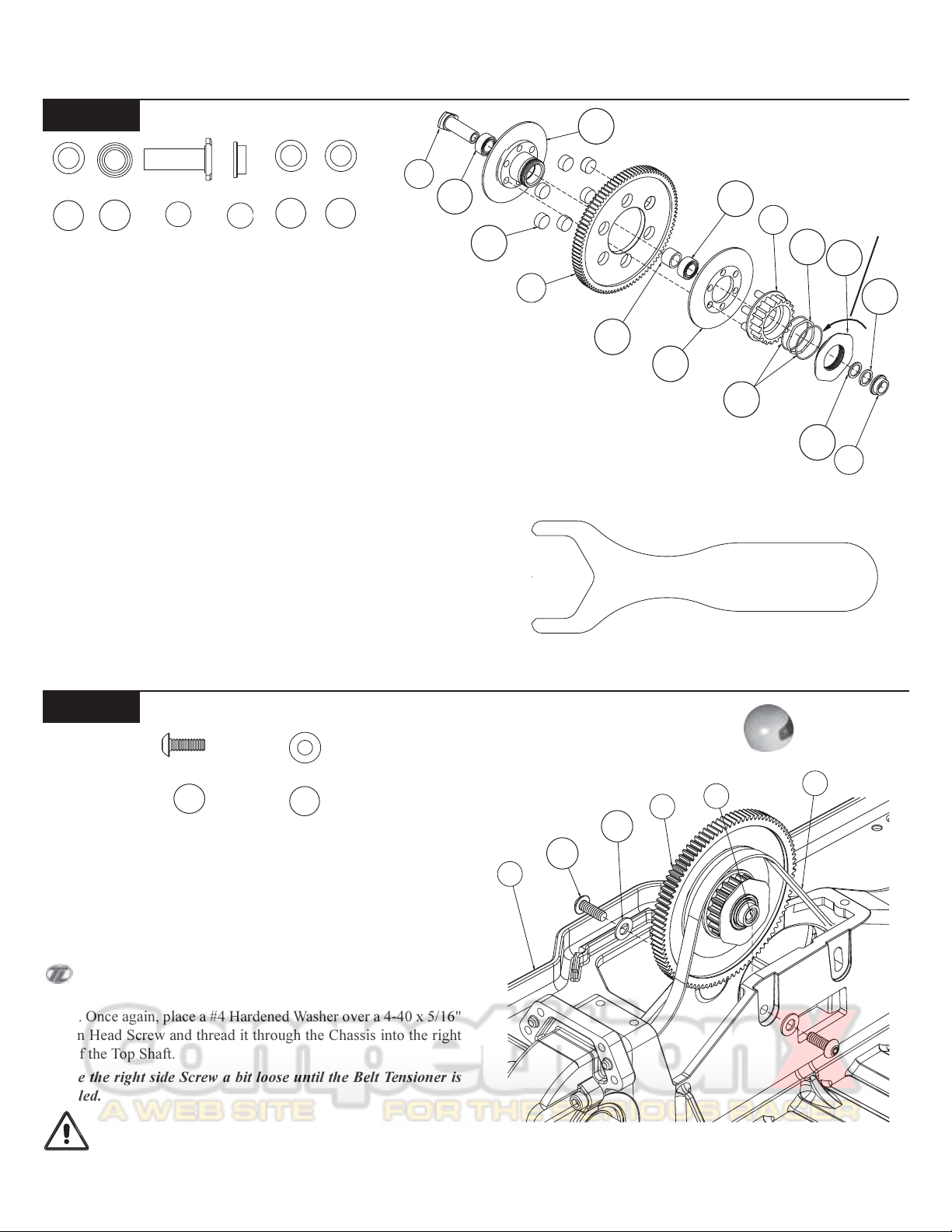
Step B-5
Slipper Clutch Assembly:
99
119
106
119
99
96
196 197
q 1. Press a 3/16" x 5/16" Bearing (119) into the Slipper Hub (103)
from the outside/large face. Slide the Top Shaft (99) through the Bearing in the Slipper Hub.
q 2. Place the Spur Gear (71) onto the Slipper Hub and place all six
of the Slipper Pucks (156) into the holes in the Spur Gear.
q 3. Fr om t he " Dri ve P ull ey" (70) side of the Slipper Clutch assem-
bly, slide the Slipper Bearing Spacer (106) over the Top Shaft. Place
the second 3/16" x 5/16" Bearing over the Top Shaft and press the
Bearing into the Slipper Hub.
q 4. Place the flat face of the Slipper Plate (104) against the Slipper
Pucks in the Spur Gear. Then press the 6 pins of the Drive Pulley (70)
through the holes in the Slipper Plate continuing through the center
hole of the Spur Gear and into the 6 holes in the Slipper Hub.
q 5. Insert A Slipper Spring Shim (155) followed by the Slipper Wave
Spring (123), then another Slipper Spring Shim, into the Slipper Drive
Pulley and thread the Slipper Flange (105) Counter Clockwise onto
Slipper Hub until it is "finger tight". Place one .005 Shim (196) and
one 0.015 Shim (197) on the Top Shaft next to the Bearing. Slide the
Tensioner Bushing (96), large side toward Slipper Hub, over the Top
Shaft, against the Shims.
q 6. The Slipper Wrench will be used for the final adjustment of the
Clutch assembly in the Final Checklist section in the back of this
manual.
Step B-6
Slipper Clutch Insert:
156
71
Figure 24A
Figure 25
103
106
119
104
155
Slipper Wrench
Figure 24B
70
123
196
Tighten
105
197
96
146
151
q 1. While holding the Slipper Clutch assembly, with your thumb
and index finger, pull the Belt (77) up through the Chassis (46) and
insert the assembly into the large opening in the top of the Chassis
lining up the Top Shaft (99) with the holes in the Chassis.
q 2. Place a #4 Hardened Washer (151) over a 4-40 x 5/16" Button
Head Screw (146) and thread it through the left side of the Chassis
into the Top Shaft.
You may need to slightly pinch the Chassis to install the 4-40 x
5/16" Button Head Screws.
q 3. Once again, place a #4 Hardened Washer over a 4-40 x 5/16"
Button Head Screw and thread it through the Chassis into the right
side of the Top Shaft.
Leave the right side Screw a bit loose until the Belt Tensioner is
installed.
IMPORTANT NOTE: Never pinch the Belt, as it will result
in a shorter life of the Belt and cause your vehicle to stop running!
10
46
146
151
71
99
77
BAG B (Continued)
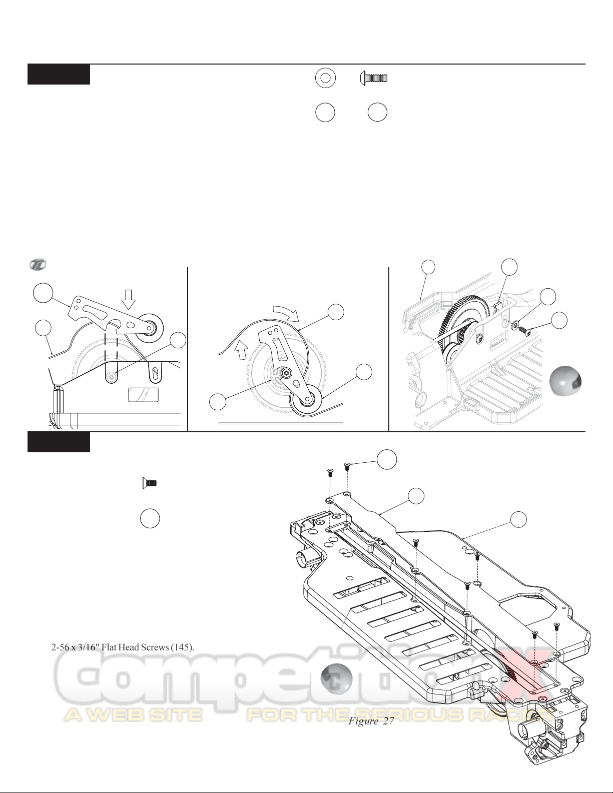
Step B-7
Tensioner Arm Installation:
151
146
q 1. Slide the Tensioner Arm assembly (110) down over the Belt (77) and connect the slot in the Tensioner Arm with the Slipper Clutch
assembly's Belt Tensioner Bushing (96) as indicated in Figure 26A.
q 2. Slowly start rotating the Tensioner Arm assembly around the Belt Tensioner Bushing in a clockwise direction as shown in Figure 26B.
While rotating the Tensioner Arm assembly, slightly pull upward to keep the Tensioner Arm locked and rotating around the Belt Tensioner
Bushing. The Belt should be positioned between the Slipper Drive Pulley (70) and the Tensioner Arm.
q 3. Place a #4 Hardened Washer (151) over a 4-40 x 5/16" Button Head Screw (146).
q 4. Once you have the belt wrapped around the Slipper Drive Pulley, and Belt Tensioner is in position, as shown in Figure 26C, secure the
Tensioner assembly by threading the 4-40 x 5/16" Button Head Screw, with Washer through the Chassis (46) and into the upper hole in the
Tensioner Arm. With the Screw about one turn loose, push down on the flat part of the Tensioner and set the desired Belt tension, tighten the
Screw.
The belt should move 1/8" (3mm) to 1/4" (7.5mm) up and down for the ideal tension.
Figure 26A
110
77
96
Figure 26B
77
Figure 26C
46
110
151
146
70
Step B-8
Bottom Cover Installation:
145
q 1. With the Chassis facing upside down, seal the drivetrain by
placing the Bottom Chassis Cover (61) with the flat side towards the
Bottom of the Chassis (46). Secure the Bottom Chassis Cover with
seven 2-56 x 3/16" Flat Head Screws (145).
44
145
61
46
11
Figure 27
 Loading...