

USER GUIDE
RADION 8140
Automatic sprayer control
Software version 1.05

Safety information
TeeJet Technologies is not responsible for damage or physical harm caused by failure to adhere to the following safety
requirements. As the operator of the vehicle, you are responsible for its safe operation. The Radion 8140 in combination with any
assisted/auto steering device is not designed to replace the vehicle’s operator. Do not leave a vehicle while the Radion 8140 is engaged.
Ensure the area around the vehicle is clear of people and obstacles before and during engagement. The Radion 8140 is designed to support
and improve efciency while working in the eld. The driver has full responsibility for the quality and work related results. Disengage or
remove any assisted/auto steering device before operating on public roads.

iii
98-01467-EN R1
Radion 8140 automatic sprayer control
Table of Contents
NO.1 POWER ON, SWITCHES 1
Boom sections & Switches ........................................................................................................................................1
NO.2 OPERATION SCREEN 2
Operation menu ..............................................................................................................................................................................................2
Information bar ...............................................................................................................................................................................................3
Regulation modes ..........................................................................................................................................................................................3
Manual regulation mode ............................................................................................................................................3
NO. 3 GO TO HOME 4
1 SET UP THE LOCAL CULTURAL SETTINGS 4
2 SET UP THE JOB PARAMETERS 4
Establish preset target application rates ....................................................................................................................4
3 SET UP THE MACHINE 5
Operation ..........................................................................................................................................................................................................5
Implement parameters .................................................................................................................................................................................6
Section configuration .................................................................................................................................................6
Nozzle preset setup ..................................................................................................................................................6
Establish nozzle presets ............................................................................................................................................7
Calibrations .......................................................................................................................................................................................................7
NO. 4 START NEW JOB OR CONTINUE JOB 9
Jobs ......................................................................................................................................................................................................................9
SENSOR CALIBRATIONS 10
Implement speed sensor .........................................................................................................................................10
Flow sensor.............................................................................................................................................................10
Liquid pressure sensor ............................................................................................................................................ 11
Fill flow sensor ........................................................................................................................................................13
Tank level sensor ....................................................................................................................................................14
OPERATION SCREEN 17
INFORMATION BAR 17
Selectable information .............................................................................................................................................................................. 17
Application rate ............................................................................................................................................................................................ 18
Select target application rate ...................................................................................................................................18
Target rate percentage increase/decrease ...............................................................................................................19
Change application rate step ...................................................................................................................................19

iv
www.teejet.com
Radion 8140 automatic sprayer control
NOZZLE SELECTION 20
Selecting the current nozzle ....................................................................................................................................20
Presetting nozzles ...................................................................................................................................................20
TANK 21
ALARM WARNING 21
PRESSURE GAUGE 22
BOOM SECTIONS & SWITCHES 22
ALARM CONFIGURATIONS 23
1
98-01467-EN R1
Radion 8140 automatic sprayer control
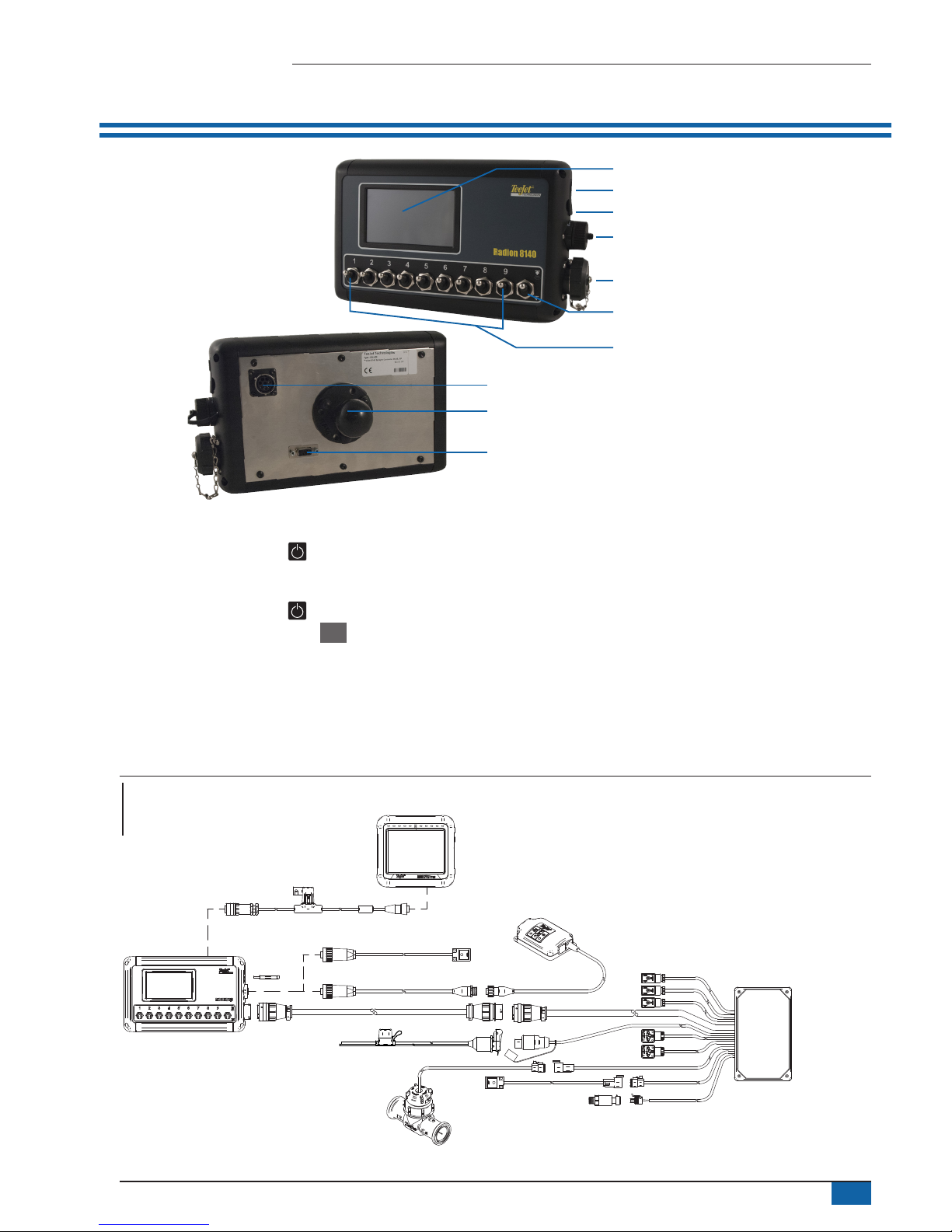
NO.1 POWER ON, SWITCHES
Integrated RAM mount
(assembly required)
Power button
USB port with rubber cover
Speed cable connection
Main cable connection
Serial connection
Master switch
Bright touch screen
CAN connection
Boom section controls
(switches 1 to 5 or 1 to 7 or 1 to 9,
depends on console)
Power On/Off Button
On – Press the POWER button to power on the console. Upon
power up, the Radion will begin its start up sequence. Once start up
is complete, the Operation screen appears.
Off – Press the POWER button . On the conrmation screen to
acknowledge shut down mode, press Yes to power off the console.
WARNING! Wait 10 seconds before restarting the console.
Boom sections & Switches
The console operates with nine (9), seven (7) or ve (5) section
switches (depending on console model) and one (1) Master switch.
Each section switch is associated with one of up to the same number
of sections on the boom and illustrated on the Operation screen.
►Switches – control individual boom sections
◄On – Flip the switch up
◄Off – Flip the switch down
►Master switch – opens/closes the main product valves and
enables/disables power to individual boom section on/off
switches
Figure 1: System diagram
Radion 8140 sprayer controller
(available in 5 sections,
7 sections or 9 sections)
98ET05-S13-4
Extension for
main cable, 4 m
Spray cable -
flow/pressure/speed
199-315: 5 section, 8 m
199-311: 7 section, 8 m
199-319: 9 section, 8 m
* Unlock code necessary to activate
the BoomPilot function, contact TeeJet Technologies.
** Only one speed source at the same time.
Flow meter
Pressure sensor
570-001: 10 bar ¼ NPT
570-002: 25 bar ¼ NPT
96ET10-8D **
Speed sensor
proximity, 8 m
96ET14 Cable,
battery to COBO,
4 m
98-50139
USB stick
99ET017-6** Speed sensor proximity, 6 m
90-02371 GPS speed sensor
198-669 ** GPS speed adapter cable
Matrix Pro console
Cable, BoomPilot adapter cable,
Radion to Matrix Pro
197-100*: Direct
197-101*: CAN/power/data cable
Radion
Matrix Pro & BoomPilot
Optional Accessory
2
www.teejet.com
Radion 8140 automatic sprayer control
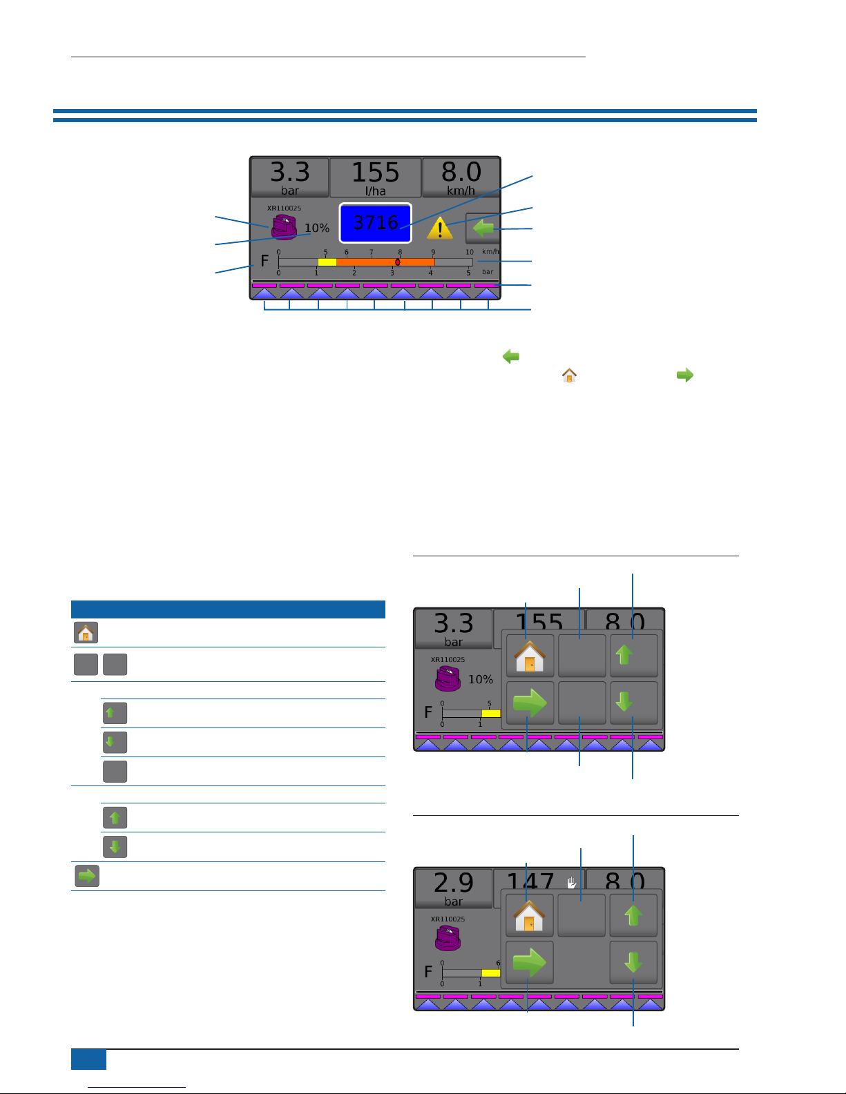
NO.2 OPERATION SCREEN
Boom sections
Spray status
Pressure gauge
Current nozzle
Information bar
Current droplet size
Tank contents / lling options
Alarm warning
Options tab
Application rate change
►Information bar – displays application rates and selectable
information
►Current nozzle – displays current nozzle and accesses ve (5)
preset nozzle types
►Application rate change – displays rate changes (if in
Automatic regulation mode)
►Tank – displays remaining tank contents and accesses lling
options
◄Filling – establishes actual/desired tank material/density
►Alarm warning – displays active alarm conditions
►Options tab – accesses the Operation menu
◄Displays Home button , Close Menu button ,
regulation modes and target rate options
►Pressure gauge – displays current pressure range compared
with recommended pressure range
◄Droplet size – displays selected droplet size
►Boom sections – displays congured boom sections
◄Spray status – displays active/inactive for section
Operation menu
The Options tab is always available on the Operation screen. This
tab accesses the Operation menu where the Home button, regulation
modes and target rate options display.
Operation menu buttons
Home
Auto
reg
Man
reg
Change between automatic/manual regulation
modes
Automatic regulation mode
5%
Target rate boost percent increase
5%
Target rate boost percent decrease
0%
Return to target rate
Manual regulation mode
Regulation valve manual open
Regulation valve manual close
Close menu
Figure 2: Options tab – Automatic mode
0%
Man
reg
5%
5%
Regulation mode
Target rate reset
Boost/step percent increase
Boost/step percent decrease
Home
Close menu
Figure 3: Options tab – Manual mode
Auto
reg
Regulation mode
Valve open
Valve close
Home
Close menu
3
98-01467-EN R1
Radion 8140 automatic sprayer control
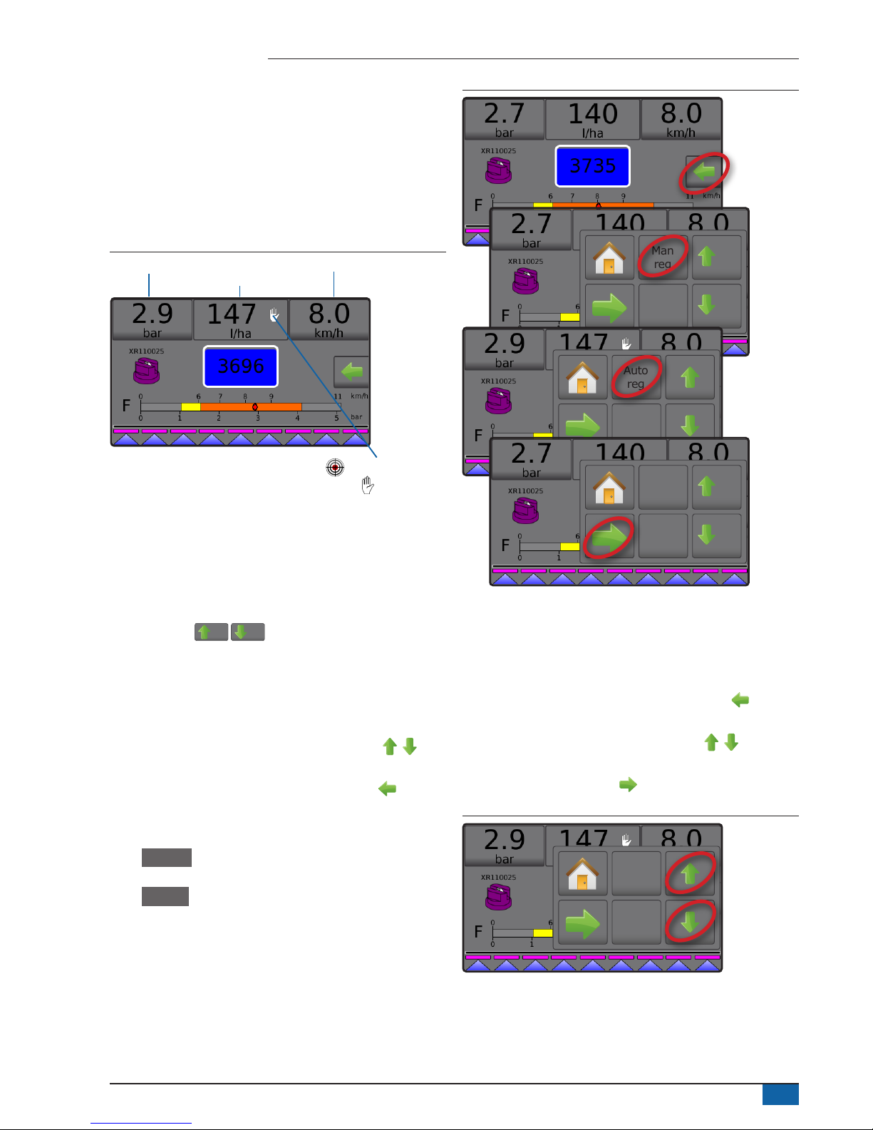
Information bar
The information bar displays:
►Application rate – displays the actual application rate or target
application rate and accesses the preset target application
rates options menu.
►Selectable information – displays user-selected information
including volume applied, ow rate, ow pressure, speed, total
area applied and job number.
Figure 4: Information bar
Selectable information Selectable information
Application rate
Target application rate
Manual mode
Regulation modes
Automatic regulation mode will automatically adjust the application
rate based on the current speed in reference to the target rate. The
target rate can be adjusted using the Boost/step percent increase/
decrease buttons
5%/5%
on the Operation menu. Preset
application rates dene up to three (3) target rates for product being
applied per hectare/acre. These can be toggled using the Application
rate section on the Information bar on the Operation screen.
Manual regulation mode will retain an established regulation valve
setting regardless of speed. The regulation valve setting can be
adjusted using the Regulation valve open/close buttons on
the Operation menu.
1. From the Operation screen, press the OPTIONS tab to display
the Operation menu.
2. Select from:
► Auto reg to change from Manual regulation mode to
Automatic regulation mode:
► Man reg to change from Automatic regulation mode to
Manual regulation mode:
NOTE: The Regulation button displays the regulation mode that may
be selected not the active regulation mode.
Figure 5: Regulation options: Automatic / Manual
0%
Man
reg
5%
5%
Auto
reg
0%
Man
reg
5%
5%
Manual regulation mode
Manual regulation mode will retain an established regulation valve
setting regardless of speed.
To open/close the valve:
1. From the Operation screen, press the OPTIONS tab to display
the Operation menu.
2. Press the Regulation valve open/close buttons to
manually turn the valves on/off.
3. Press the Close menu button .
Figure 6: Manual regulation mode
Auto
reg
4
www.teejet.com
Radion 8140 automatic sprayer control
NO. 3 GO TO HOME
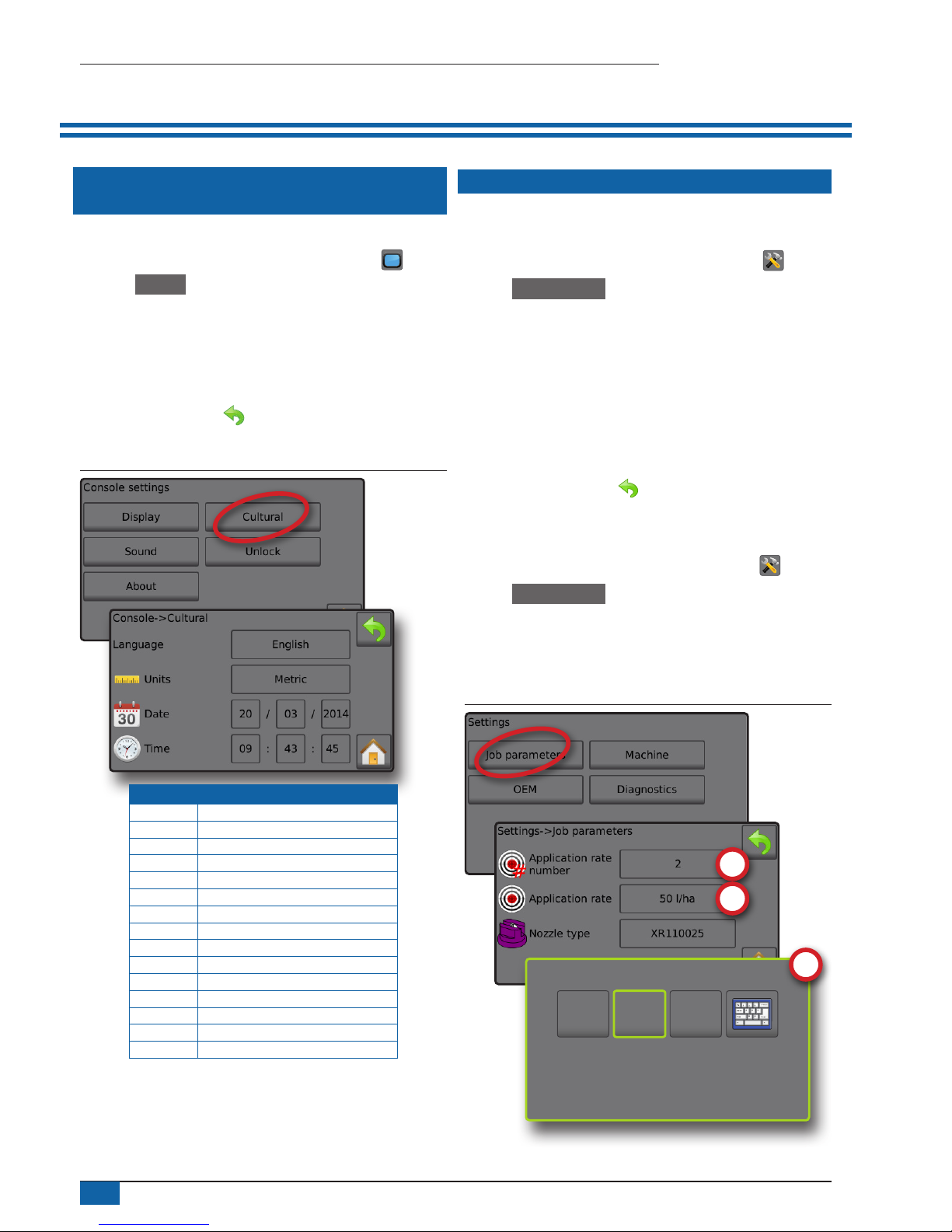
1 SET UP THE LOCAL CULTURAL
SETTINGS
Cultural congures language, units, date and time settings.
1. From the Home screen, press the CONSOLE button .
2. Press Cultural .
3. Select from:
►Language – denes the system language
►Units – denes the system measurements
►Date – establishes the date
►Time – establishes the time
4. Press RETURN arrow to return to the main Console settings
screen.
Figure 7: Cultural options
Code Language
cs Czech
da Danish
de-DE German
en-GB English (international)
en-US English (USA)
es-ES Spanish (Europe)
es Spanish (Central/South America)
fr-FR French
hu Hungarian
it-IT Italian
nl Dutch
pl Polish
pt-BR Portuguese (Brazil)
ru Russian
sk Slovak
NOTE: Some languages listed may not be available on the console.
2 SET UP THE JOB PARAMETERS
Job parameters congures the target application rate settings and
current nozzle. Selections are also active on the Operation screen.
1. From the Home screen, press the SETTINGS button .
2. Press Job parameters .
3. Press a setting value to adjust settings as needed.
◄ Target application rate number – species up to three (3)
target application rate presets from which to select
◄ Target application rate – denes the target rate of product to
apply for the selected number (these settings will be the same
for all active jobs)
◄ Nozzle type – selects the current nozzle type from the ve (5)
nozzle presets
4. Press the RETURN arrow to return to the main Settings
screen.
Establish preset target application rates
1. From the Home screen, press the SETTINGS button .
2. Press Job parameters .
3. Select Application rate number 1 .
4. Select an application rate to be associated with number 1.
5. Repeat steps 3 and 4 for Application rate numbers 2 and 3.
Figure 8: Establish preset target application rate 2
225
l/ha
50
l/ha
100
l/ha
5
98-01467-EN R1
Radion 8140 automatic sprayer control
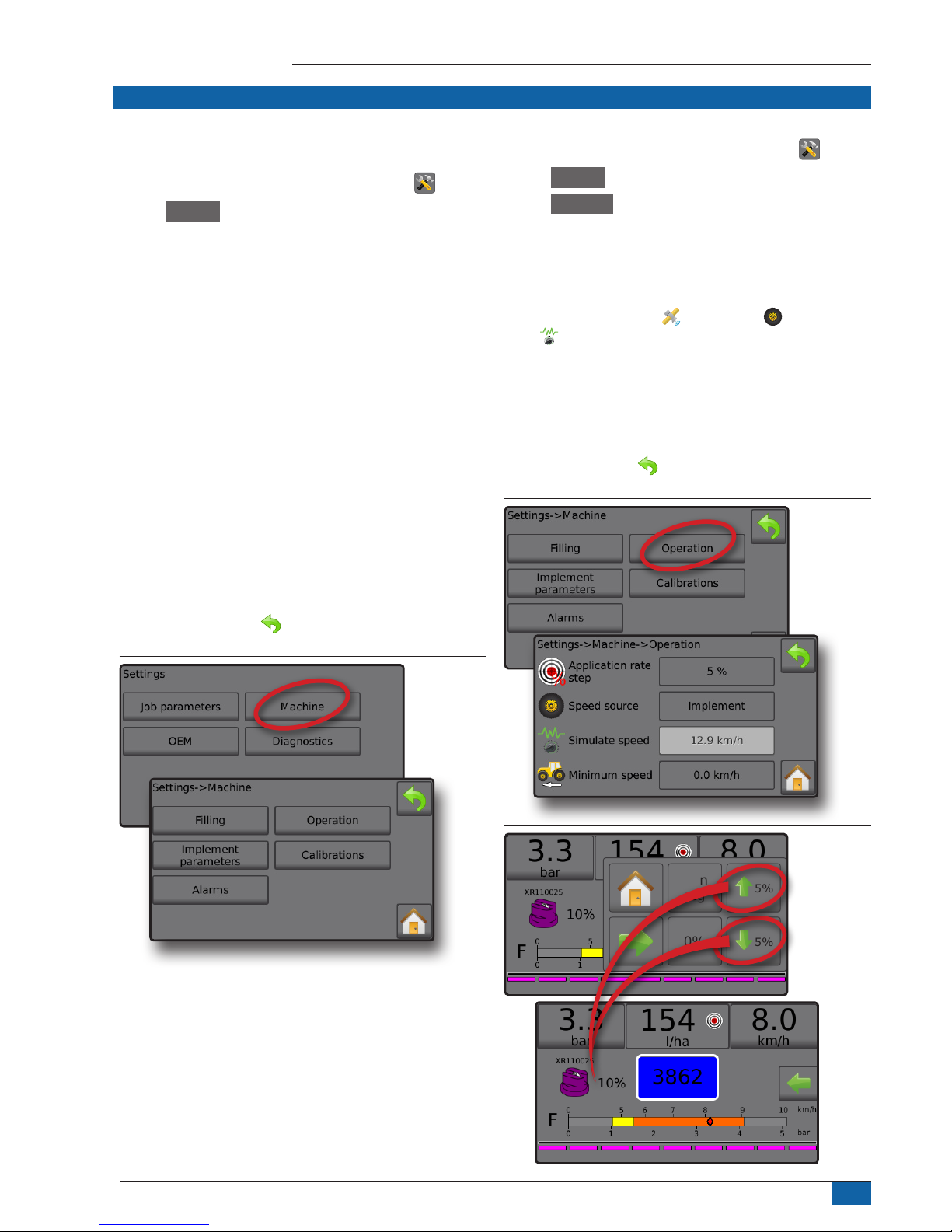
3 SET UP THE MACHINE
Machine congures machine settings. Options include Filling,
Operation, Implement parameters, Calibrations and Alarms.
1. From the Home screen, press the SETTINGS button .
2. Press Machine .
3. Select from:
►Filling – establishes the amount of actual and desired material
in the tank and the density of that material
►Operation – establishes application rate step, speed source,
simulated speed and minimum speed
►Implement parameters
◄ Section conguration – sets the number of nozzles on
the boom which determines the spraying width during
application
◄ Nozzle preset setup – establishes options for up to ve (5)
nozzles including series, capacity, low/high pressure limits,
reference ow and reference pressure
◄ Regulation parameters – adjusts valve calibration and
nozzle spacing and selects a regulation mode
►Calibrations – establishes either manual/automatic settings
of the Implement speed sensor, Flow sensor, Liquid pressure
sensor, Fill flow sensor and Tank level sensor
►Alarms – establishes alarms on/off and sets their trigger levels
4. Press RETURN arrow to return to the main Settings screen.
Figure 9: Machine
Operation
1. From the Home screen, press the SETTINGS button .
2. Press Machine .
3. Press Operation .
4. Press setting value to adjust settings as needed:
◄Application rate step – the percent of increase/decrease boost
of the active application rate at which the product is applied
◄Speed source – selects whether to base the machine speed
on input from the CAN , an Implement or a Simulated
source
◄Simulated speed – establishes a speed for using the
Simulated speed source
◄Minimum speed – establishes the minimum forward speed at
which the system should automatically switch the main valve
off
5. Press RETURN arrow to return to the Machine screen.
Figure 10: Operation
Figure 11: Application rate step on Operation screen
0%
Man
reg
5%
5%

6
www.teejet.com
Radion 8140 automatic sprayer control
Implement parameters
1. From the Home screen, press the SETTINGS button .
2. Press Machine .
3. Press Implement parameters .
4. Select from:
►Section conguration – sets the number of nozzles on the
boom which determines the spraying width during application
►Nozzle preset setup – where up to ve (5) sets of nozzle
options can be established to set the nozzle series, capacity,
low/high pressure limit, reference ow and reference pressure
►Regulation parameters – where adjustments to the valve
calibration, nozzle spacing and regulations mode can be
established
5. Press RETURN arrow to return to the Machine screen.
Figure 12: Implement parameters
Section configuration
Section conguration sets the number of nozzles on the boom which
determines the spraying width during application.
1. From the Home screen, press the SETTINGS button .
2. Press Machine .
3. Press Implement parameters .
4. Press Section conguration .
5. Press setting value to adjust settings as needed:
◄Section number – establishes the current section number to
which changes can be made. Sections are numbered from left
to right while facing in the machine forward direction
◄Number of nozzles – establishes the number of nozzles in the
current section number
◄Copy section – sets all Number of nozzles counts to the same
count for all boom sections based upon the current Section
number
◄Section width – displays the width for the current section
6. Press RETURN arrow to return to the Implement parameters
screen.
Establish number of nozzles
1. From the Home screen, press the SETTINGS button .
2. Press Machine .
3. Press Implement parameters .
4. Press Section conguration .
5. Select Section number .
6. Set the number of nozzles for the selected section number.
7. Repeat steps 5 and 6 for additional Section numbers as available.
8. OPTIONAL: If all sections have the same number of nozzles,
press Copy to set all sections to the current number of
nozzles.
Figure 13: Establish number of nozzles
Nozzle preset setup
Nozzle preset setup establishes up to ve (5) sets of nozzle options
setting the nozzle type, capacity, low/high pressure limit, reference
ow and reference pressure.
NOTE: Settings on both screen 1 and screen 2 are specific to the
currently selected Nozzle preset number.
1. From the Home screen, press the SETTINGS button .
2. Press Machine .
3. Press Implement parameters .
4. Press Nozzle preset setup .
5. Press setting value to adjust settings as needed:
◄Nozzle preset (number)
◄Nozzle series
◄Nozzle capacity
◄Factory settings
◄Low pressure limit
◄High pressure limit
◄Reference ow
◄Reference pressure
6. Press RETURN arrow to return to the Implement parameters
screen.

7
98-01467-EN R1
Radion 8140 automatic sprayer control
Establish nozzle presets
1. From the Home screen, press the SETTINGS button .
2. Press Machine .
3. Press Implement parameters .
4. Press Nozzle preset setup .
5. Select Nozzle preset number 1 .
6. Select Nozzle series .
7. Select Nozzle capacity .
8. Repeat steps 5, 6 and 7 for Nozzle preset numbers 2 to 5.
9. OPTIONAL: Press NEXT PAGE arrow to adjust the
settings for Low pressure limit, High pressure limit, Reference ow
and Reference pressure. Each of these settings are specic to the
current nozzle preset number.
Figure 14: Establish nozzle presets
Calibrations
For detailed instructions on sensor calibrations, see the Sensor
calibrations section of this guide.
1. From the Home screen, press the SETTINGS button .
2. Press Machine .
3. Press Calibrations .
4. Select from:
►Implement speed sensor – establishes the wheel impulses
over a specied distance
►Flow sensor – establishes the impulses per litre through the
Flow sensor
►Liquid pressure sensor – establish the maximum pressure limit
and no pressure calibration for the liquid pressure sensor
◄Calibrate each option in the following order:
No pressure
Maximum pressure
►Fill ow sensor – establishes the impulses per litre through the
Fill ow sensor
►Tank level sensor – establishes the empty, minimum and
maximum levels for the tank and calibrates the tank shape
◄Calibrate each option in the following order:
Empty tank
Minimum tank level
Maximum tank level
Tank shape
5. Press the RETURN arrow to return to the Machine screen.
Figure 15: Calibrations – Tank level sensor and Fill flow sensor

8
www.teejet.com
Radion 8140 automatic sprayer control
SETTINGS MENU STRUCTURE
| | | |
Job parameters Machine OEM Diagnostics
Application rate number Filling Sensor presence Test inputs
Application rate Actual content Flow sensor Implement wheel sensor
Nozzle type *Full tank Liquid pressure sensor Tractor wheel sensor
Density type Fill ow sensor Supply voltage
Density factor Tank sensor Flow sensor
Implement speed sensor Desired content Implement parameters Fill ow sensor
Calibration number Automatic lling Number of sections Liquid pressure sensor
Automatic calibration Operation Circulation Tank level sensor
*Flow sensor Application rate step Section conguration Valve setup Remote master signal
Calibration number Speed source Section number Regulation valve type Master switch
Low ow limit Simulate speed Number of tips Section valve type Section switches
High ow limit Minimum speed Copy section Section valve behaviour Test outputs
Automatic calibration Implement parameters Section width Tank setup Liquid valve PWM duty cycle
*Liquid pressure sensor Calibrations Nozzle preset setup Maximum tank content Master valve
No pressure Alarms Nozzle preset Minimum tank content Fill valve
No pressure calibration Minimum tank content Nozzle series Automatic lling Section number
Maximum pressure Flow/pressure cross check Nozzle capacity Automatic lling offset Section valve state
Maximum pressure Section output low Factory settings Regulation details All sections off
Reference pressure Low pressure limit Minimum regulation pressure Test boompilot
Automatic calibration High pressure limit Maximum regulation pressure Connection
*Fill ow sensor Reference ow Regulation valve time Mode
Calibration number Reference pressure Minimum regulation voltage Section input
Automatic calibration Regulation parameters Regulation deadband Alarm log
*Tank level sensor Course value calibration Regulation valve capacity Save alarm log
Empty tank Fine value calibration Regulation start delay
Automatic calibration Nozzle spacing Manual regulation speed
Minimum tank level Regulation mode Restrictor plate ow
Minimal tank level Clear totals
Automatic calibration Area counter
Maximum tank level Volume counter
Maximum tank level Time counter
Automatic calibration Clear all total counters
Tank shape Import/export calibrations
Maximum tank level
Start calibration
Import/export calibrations
OEM menu is password protected.
*Menu settings directly related to fitted OEM equipment.

9
98-01467-EN R1
Radion 8140 automatic sprayer control
NO. 4 START NEW JOB OR CONTINUE JOB
The Data option, provides an overview of various system
counters including job counters, campaign counters and total
counters. From Data options screens, export as either PDF or
CSV reports.
6. From the Home screen, press the DATA button
7. Select from:
►Jobs – displays, deletes and reports on job information
►Campaign – displays and deletes campaign information
►Totals – displays all counter information
►CSV – compiles a CSV report of counters for all jobs, and for
the campaign and console totals, then saves reports to a USB
drive
Figure 16: Data management options
Jobs
One of up to ten (10) jobs may be selected to view job information.
The current job, displayed/active on the Operation screen, may be
exported as a PDF report.
Job information includes:
◄Job number of information displayed
◄Current date
◄Applied area
◄Volume of material applied
◄Distance travelled
◄Time travelled
1. From the Home screen, press the DATA button .
2. Press Jobs .
3. Press Job number to view information for a different job.
◄Enter any number to display another job
4. Press RETURN arrow to return to the main Data screen.
Figure 17: Job data
Job data report
The PDF button compiles active job information to be exported as a
PDF report.
1. From the Home screen, press the DATA button .
2. Press Jobs .
3. Select the job from which to create a report.
4. Insert USB drive into the console and wait for PDF button
PDF
to
activate.
5. Press PDF button
PDF
.
6. Press RETURN arrow to return to the main Data screen.
NOTE: The PDF icon
PDF
is not available for selection (greyed out)
until a USB drive is inserted properly.
Figure 18: Job data

10
www.teejet.com
Radion 8140 automatic sprayer control
SENSOR CALIBRATIONS
Implement speed sensor
The Implement speed sensor establishes the wheel impulses over
a specied distance. Establish the value manually or automatically
calibrate the value.
►Calibration number –
◄Automatic calibration will determine the number of impulses
counted while driving 100 metres and convert the calibration
number to the correct units.
◄Manual calibration, enter the calibration number in impulses
per 100 meters
►Automatic calibration – establishes the impulses using the
automatic calibration function.
Figure 19: Implement speed sensor
Implement speed sensor automatic calibration
1. Press Calibrate to start an automatic sensor calibration.
2. Drive a distance of 100 metres.
3. Press Done when complete.
To cancel the calibration, press Cancel , RETURN arrow or the
Home button .
The counted wheel impulses will be displayed during the automatic
calibration.
Flow sensor
The Flow sensor establishes the impulses per litre. Establish the
value manually or automatically calibrate the value.
►Calibration number – enter the amount of impulses counted
while running 1 litre of water through the ow sensor. Use
Automatic calibration to calculate impulses automatically.
Manual calibration establishes the calibration and limits based
on user-entered values.
►Low ow limit – enter the ow sensors low limit value.
►High ow limit – enter the ow sensors high limit value.
►Automatic calibration – establishes the calibration and limits if
the number of impulses per litre for the ow meter is unknown
or to make sure the value is correct.
►Impulse count – shows the number of impulses during
calibration. Minimum of 10 impulses needed to do a
calibration.
►Collected volume – enter the volume passed through the
ow sensor during the calibration. Once encoded, a new ow
sensor calibration value is calculated.
►Master switch status / Cancel – shows if the Master switch is
off or on .
Press the Cancel to cancel the calibration and return to the
Flow sensor screen.
Figure 20: Flow sensor

11
98-01467-EN R1
Radion 8140 automatic sprayer control
Flow sensor automatic calibration
1. Press Calibrate to enter automatic calibration mode.
2. Prepare to collect the ‘medium’ via the Flow sensor (minimum
100 litres).
3. Make sure the controller is in manual mode and ow is not
regulated down.
4. Turn on the Master switch to start ow and calibration.
◄Impulses counted display during the automatic calibration
5. Once at the minimum 100 litres has distributed, turn off
Master switch to stop calibration.
6. Press the Collected volume value .
7. Enter the precise volume which passed through the ow sensor
during the calibration.
Once encoded, a new ow sensor calibration value is calculated.
To cancel the calibration, press Cancel , RETURN arrow or the
Home button .
Figure 21: Automatic calibration
Liquid pressure sensor
The liquid pressure sensor settings establish the maximum pressure
limit and no pressure calibration for the liquid pressure sensor.
1. From the Home screen, press the SETTINGS button .
2. Press Machine .
3. Press Calibrations .
4. Press Liquid pressure sensor .
5. Calibrate each option in the following order:
No pressure
Maximum pressure
6. Press RETURN arrow to return to the Calibrations screen.
Figure 22: Liquid pressure sensor
No pressure
Liquid pressure sensor->No pressure establishes the calibration
while NO pressure is applied to the liquid pressure sensor.
1. Remove all pressure from the system.
2. Press Calibrate to record a new calibration value and nalise the
calibration.
NOTE: Manual calibration is not available.
Figure 23: Liquid pressure sensor->No pressure

12
www.teejet.com
Radion 8140 automatic sprayer control
Maximum pressure
Liquid pressure sensor->Maximum pressure establishes the
maximum allowed pressure limit for the liquid pressure sensor.
The automatic calibration is based on the recommended maximum
pressure level and a tested reference pressure level.
►Maximum pressure – enter the maximum allowed pressure
limit for the liquid pressure sensor. Use Automatic calibration
to calculate the maximum pressure automatically.
►Reference pressure – enter the pressure value used as
reference for the actual liquid pressure sensor calibration.
The reference pressure can be changed, but not while in the
calibration mode.
►Automatic calibration – if the maximum pressure is not known,
or to make sure the value is correct, automatic calibration
establishes the calibration.
►Complete calibration – apply constant reference pressure to
the sensor. Press “Done” when complete.
►Master switch status / Pressure adjustment –
Shows if the Master switch is off or on .
Press the UP/DOWN arrows to increase/decrease
the pressure until reaching and maintaining the reference
pressure.
►Minimum/maximum pressure bar – illustrates the change in
pressure from minimum to maximum.
Figure 24: Liquid pressure sensor->Maximum pressure
Maximum pressure automatic calibration
IMPORTANT: Make sure all section valves are open before opening
the Master valve; otherwise, the pressure could build and
damage the system.
1. Press the Reference pressure value .
2. Enter the pressure value used as reference for the actual liquid
pressure sensor calibration.
3. Press Calibrate to start an automatic calibration of the sensor.
4. Turn on Master switch .
5. Press the UP/DOWN arrows to increase/decrease the
pressure until reaching and maintaining the reference pressure.
6. Apply constant reference pressure to the sensor.
7. Press Done when complete.
8. Turn off Master switch to stop calibration.
To cancel the calibration, press the RETURN arrow or the Home
button .
Figure 25: Automatic maximum pressure

13
98-01467-EN R1
Radion 8140 automatic sprayer control
Maximum pressure manual calibration
1. Press the Maximum pressure value .
2. Enter the maximum allowed pressure limit for the liquid pressure
sensor.
Figure 26: Manual maximum pressure
Fill flow sensor
The Fill ow sensor establishes the impulses per litre. The Fill ow
value can be established manually or automatically calibrated.
►Calibration number – enter the amount of impulses counted
while running one (1) litre of water through the Fill ow
sensor. Use Automatic calibration to calculate the impulses
automatically. Manual calibration establishes the calibration
and limits based on user entered values.
►Automatic calibration – establishes the calibration if the
number of impulses per litre for the Fill ow meter is unknown,
or to make sure the value is correct.
►Impulse count – number of impulses calculated during
automatic calibration.
►Collected volume – enter the collected volume.
►Automatic calibration done – to complete the automatic
calibration, press “Done” when collected volume has been
entered.
Figure 27: Fill flow sensor
Fill flow sensor automatic calibration
1. Press Calibrate to enter automatic calibration mode.
2. Prepare to collect the ‘medium’ via the Fill ow sensor (minimum
of 100 litres).
3. Turn on Master switch to start ow.
4. Press START CALIBRATION button .
◄Impulses counted display during automatic calibration
5. Once the desired amount has distributed, press the STOP
CALIBRATION button .
6. Turn off the Master switch .
7. Press the Collected volume value .
8. Enter the precise volume passed through the Fill ow sensor
during the calibration.
9. Press Done to complete the automatic calibration.
To cancel the calibration, press RETURN arrow or the Home
button .

14
www.teejet.com
Radion 8140 automatic sprayer control
Figure 28: Fill flow sensor automatic calibration
Tank level sensor
Tank level sensor establishes the empty, minimum and maximum
levels for the tank and calibrates the tank shape. Tank level sensor
calibration settings can be exported to a USB drive and recalled for
future use.
NOTE: Manual calibration is not available for any Tank level sensor
calibrations.
1. From the Home screen, press the SETTINGS button .
2. Press Machine .
3. Press Calibrations .
4. Press Tank level sensor .
5. Calibrate each option in the following order:
Empty tank
Minimum tank level
Maximum tank level
Tank shape
6. Press RETURN arrow to return to the Calibrations screen.
Figure 29: Tank level sensor

15
98-01467-EN R1
Radion 8140 automatic sprayer control
Empty tank – Automatic calibration
Empty tank establishes the empty tank value.
IMPORTANT: The tank should be completely empty.
1. Press Calibrate to record a new calibration value and nalise the
calibration.
◄The low-high graph should be empty
Figure 30: Tank level sensor – Empty tank
Minimum tank level – Automatic calibration
Minimum tank level establishes the minimum level of water on the
tank sensor.
IMPORTANT: Make sure the tank is filled with the contents displayed
on the screen. The amount displayed is established in
Settings->OEM->Tank setup->Minimum tank content.
1. Press Calibrate to record a new calibration value and nalise the
calibration.
◄The low-high graph should display approximately 5% full
Figure 31: Tank level sensor – Minimum tank level
Maximum tank level – Automatic calibration
Maximum tank level establishes the maximum level of water on the
tank sensor.
IMPORTANT: Ensure the tank is filled with the contents displayed on
the screen. The amount displayed is established in Settings
-
>OEM->Tank setup->Maximum tank content.
1. Press Calibrate to record a new calibration value and nalise the
calibration.
◄The low-high graph should display 100% full
Figure 32: Tank level sensor – Maximum tank level

16
www.teejet.com
Radion 8140 automatic sprayer control
Tank shape – Automatic calibration
Tank shape establishes the tank shape.
1. Flip Master switch to start calibration.
◄Tank level sensor graph will go from high to low as the
calibration proceeds
◄When Calibration progress graph reaches 100%, calibration
will record a new calibration value and nalise the calibration
To pause the calibration process, ip the Master switch.
To cancel the calibration, press RETURN arrow or press the
Home button .
Figure 33: Tank level sensor – Tank shape
Import / export
Tank level sensor calibration settings can be exported to USB drive
and recalled for future use.
NOTE: The import/export buttons are not available for
selection and are greyed out until a USB drive is inserted
properly.
To import the calibration settings:
1. Insert USB drive.
2. Press IMPORT button .
To export the calibration settings:
1. Insert USB drive.
2. Press EXPORT button .
NOTE: Only one (1) tank calibration settings file can be saved on
a USB drive at one time. If there is an existing file it will be
overwritten.
Figure 34: Tank level sensor – Import/export

17
98-01467-EN R1
Radion 8140 automatic sprayer control
OPERATION SCREEN
INFORMATION BAR
The information bar displays user selected information and
application rate information.
Figure 35: Information bar
Selectable information Selectable information
Application rate
Selectable information
Selectable information displays user-selected information.
1. Press either the left or right Selectable information section.
2. Select one (1) of six (6) available options to display for each side
(options depend upon equipment in use).
►Volume applied – displays volume applied for the current job
number
►Flow rate – displays current ow rate
►Flow pressure – displays current ow pressure
►Speed – displays vehicle speed
►Area applied – displays applied area for the selected job
number
►Job number – displays the current job number
Figure 36: Selectable information
Figure 37: Selectable information options
3450
l
0.2
l/min
20.0
bar
50
ha
5
Job No.
9.0
km/h
Flow rate
Job number
Volume applied
Area applied
Flow pressure
Speed
Selecting a job number
One of up to ten (10) jobs may be selected to view job information.
1. From the Operation screen, press the OPTIONS tab .
2. Press the HOME button .
3. From the Home screen, press the DATA button .
4. Press Jobs .
5. Press Job number to select current job number.
6. Press the HOME button .
7. From the Home screen, press the OPERATION button .
Figure 38: Selecting a job number
0%
Man
reg
5%
5%

18
www.teejet.com
Radion 8140 automatic sprayer control
Application rate
Application rate displays or give access to:
►Application rate – while application is active, displays the
actual application rate
►Target application rate – while application is inactive, displays
the target rate of product to apply.
◄Automatic regulation mode – Target application rate symbol
will be active
Use the Boost/step percent increase/decrease
buttons
5%/5%
to adjust the target application rate
◄Manual regulation mode – manual regulation symbol will
remain active
►Preset target application rates options menu – denes the
target rate of product to apply for the selected number. These
settings will be the same for all active jobs. Range is 0 to
6,554 litres/hectare.
Select target application rate
1. Press the Application rate section.
2. Select one (1) of up to three (3) preset application rates.
Figure 39: Select target application rate
140
l/ha
225
l/ha
180
l/ha
Change preset target application rate
The selected target rate can be changed either on the Operation
screen or in Settings->Job parameters.
Operation
1. Press the Application rate section.
2. Select the target application rate to be changed.
3. Press KEYBOARD button .
4. Select an application rate.
NOTE: Value must be between 0 and 6,554 litres/hectare.
Figure 40: Application rate number
140
l/ha
225
l/ha
180
l/ha
140
l/ha
225
l/ha
180
l/ha
Application rate (l/ha)
1 2 3
165
Clear
4 5 6 <--
7 8 9
0 . +/-
140
l/ha
225
l/ha
165
l/ha

19
98-01467-EN R1
Radion 8140 automatic sprayer control
Settings
1. From the Home screen, press the SETTINGS button .
2. Press Job parameters .
3. Select Application rate number 1 .
4. Select an application rate to be associated with number 1.
5. Repeat steps 3 and 4 for Application rate numbers 2 and 3.
Figure 41: Establish preset target application rate 2
225
l/ha
50
l/ha
100
l/ha
Target rate percentage increase/decrease
Target rate boost/step percent increase/decrease buttons increase/
decrease the application target rate per the established percentage
set in the Settings->Machine->Operation setup screen under
Application rate step.
Figure 42: Target rate boost/step percent
Increase/decrease percentage
1. From the Operation screen, press the OPTIONS tab to display
the Operation menu.
2. Press the Boost/step percent increase/decrease
buttons
5%/5%
to adjust application rates.
3. Press the Close menu button .
Return to preset target rate
1. From the Operation screen, press the OPTIONS tab to display
the Operation menu.
2. Press 0% to return to the preset target rate.
3. Press the Close menu button .
Figure 43: Application rate step
0%
Man
reg
5%
5%
Change application rate step
Application rate step is the percent of increase/decrease boost of the
active application rate at which the product is applied. Range is 1 to
20%.
1. From the Home screen, press the SETTINGS button .
2. Press Machine .
3. Press Operation .
4. Press Application rate step value .
5. Select an application rate step.
6. Press RETURN arrow to return to the Machine screen.
Figure 44: Operation

20
www.teejet.com
Radion 8140 automatic sprayer control
NOZZLE SELECTION
Nozzles must be preset to be available for current nozzle selection. Presets allow saving of up to ve (5) nozzles for quick recall.
Selecting the current nozzle
1. From the Operation screen, press the CURRENT NOZZLE to
display the Preset nozzle menu.
2. Select a nozzle type from among ve (5) nozzle presets.
NOTE: Current nozzle can also be selectable on the
Settings->Job parameters screen.
Figure 45: Nozzle type on Operation screen
XR110025
XR11001
TT11004
XR110015 XR8001
Presetting nozzles
Nozzle preset setup establishes up to ve (5) sets of nozzle options
setting the nozzle type, capacity, low/high pressure limit, reference
ow and reference pressure. For more information see Settings->
Machine->Implement parameters->Nozzle preset setup.
1. From the Home screen , press the SETTINGS button .
2. Press Machine .
3. Press Implement parameters .
4. Press Nozzle preset setup .
5. Select Nozzle preset number 1 .
6. Select Nozzle series .
7. Select Nozzle capacity .
8. Repeat steps 5, 6 and 7 for Nozzle preset numbers 2 to 5.
9. OPTIONAL: Press NEXT PAGE arrow to adjust the
settings for Low pressure limit, High pressure limit, Reference ow
and Reference pressure. Each of these settings are specic to the
current nozzle preset number.
Figure 46: Establish nozzle presets

21
98-01467-EN R1
Radion 8140 automatic sprayer control
TANK
Tank displays or give access to:
►Actual content – displays the current volume of content in
the tank. Manual adjustment is directly relate to OEM tted
equipment. The volume cannot be manually adjusted if a Tank
sensor is active.
►Tank lling – establishes the amount of actual and desired
material in the tank and the density of that material. Options
displayed directly relate to OEM tted equipment. Different
options will be available depending upon if a Tank sensor or
Fill ow sensor is active. See Settings->Machine->Filling for
additional information.
1. Press TANK
100
.
2. Press setting value to adjust settings as needed:
◄Actual content (unavailable when Tank sensor is active)
◄Full tank (unavailable when Tank sensor or Fill ow sensor is
active)
◄Density type
◄Density factor (available when Density type is Fertiliser)
◄Desired content (available when Tank sensor or Fill ow
sensor is active)
◄Automatic lling (available when Tank sensor or Fill ow
sensor is active)
3. Press RETURN arrow to return to the Operation screen.
Figure 47: Tank filling
ALARM WARNING
If there is an active alarm, an Alarm warning icon will appear next to
the Tank. For a list of Alarm message codes see Appendix C – Alarm
congurations.
1. Press ALARM WARNING icon to display a list all active
alarms.
Figure 48: Active alarm warning list
Set up alarms
1. From the Home screen, press the SETTINGS button .
2. Press Machine .
3. Press Alarms .
4. Press setting value to adjust settings as needed:
◄Minimum tank content
◄Flow/pressure cross check (alarm active only when both a
Flow sensor and Liquid pressure sensor are active)
◄Section output low
5. Press RETURN arrow to return to the Machine screen.
Figure 49: Alarms

22
www.teejet.com
Radion 8140 automatic sprayer control
PRESSURE GAUGE
The Pressure gauge displays current pressure compared with the
recommended pressure range. Pressure sensor options are used to
enter the sensor manufacturer maximum pressure rating and to set
high and low user-determined pressure alarms.
Figure 50: Pressure gauge example
Speed
Pressure
Current working
pressure
Recommended pressure range
Current droplet size
Recommended pressure range
Displays the recommended pressure range for the selected nozzle.
The pressure range will change depending upon the selected
nozzle, target application rate (including boost/step percent increase/
decrease) and working speed.
IMPORTANT! Always refer to the recommended pressure range as
failure to do so may result in uneven spray patterns.
Current working pressure
Displays the current working pressure.
NOTE: This pressure range should not exceed the recommended
pressure range.
IMPORTANT! Always refer to the recommended nozzle pressure
values when setting nozzle pressure.
Current droplet size
A single nozzle can produce different droplet size classications
at different pressures. The colours displayed in the recommended
pressure range are directly associated with the current droplet
sizes. The droplet size displays as one (1) of eight (8) classication
categories.
Table 1: Droplet size chart
Category Symbol Colour code
Extremely ne XF Violet
Very ne VF Red
Fine F Orange
Medium M Yellow
Coarse C Blue
Very coarse VC Green
Extremely coarse XC White
Ultra coarse UC Black
BOOM SECTIONS & SWITCHES
The console operates with nine (9), seven (7) or ve (5) section
switches (depending on console model) and one (1) Master switch.
Each section switch is associated with one of up to the same number
of sections on the boom and illustrated on the Operation screen.
►Switches – control individual boom sections
◄On – Flip the switch up
◄Off – Flip the switch down
►Master switch – opens/closes the main product valves and
enables/disables power to individual boom section on/off
switches
◄Cannot be activated outside of the Operation screen
►Boom sections spray status – displays the status of the
section switches in association to the master switch. Number
of sections shown is established in Settings-> OEM->
Implement parameters.
◄Section on, master switch on – spray is blue
◄Section off, master switch on – spray is white
◄Master switch off – spray not shown
Figure 51: Master switch, 9 section switches
Master switchSection switchs
Figure 52: Boom sections
Boom section spray status
Master switch off
Section on, master switch on Section off, master switch on

23
98-01467-EN R1
Radion 8140 automatic sprayer control
ALARM CONFIGURATIONS
Code Message / condition Possible solution Console path
1 No ow impulses
Check ow sensor from test menu. Check components and
programming steps related to ow.
Settings->Diagnostics->Test inputs (1)->
Flow sensor
2 Low liquid pressure
Check ow sensor from test menu. Check components and
programming steps related to ow.
Settings->Machine->Implement parameters->
Nozzle preset setup (2) or Settings->Machine->
Calibrations or Settings->Diagnostics->Test inputs
(2)->Liquid pressure sensor
4 Calibration error
Check components and programming steps related to
implement or process registering a calibration error.
Settings->Machine->Calibrations - check sensors
5
Density not equal to water
(1 kg/l or 8.34 lb/gal)
Select Water for tank contents or change fertiliser density No..
Check components and programming steps related to content.
Operation->Filling (1) or Settings->Machine->
Filling (1)
6 Below minimum speed
Increase speed. Check components and programming steps
related to speed.
Settings->Machine->Operation or Settings->
Machine-> Calibrations->Implement speed sensor
7 Pressure based
Check components and programming steps related to
implement or process registering a pressure error.
Settings->Diagnostics->Test inputs or Settings->
Machine->Implement parameters->Nozzle preset
setup (2)
8 Low ow
Increase speed. Check or clean nozzles. Check components
and programming steps related to ow.
Settings->Diagnostics->Test inputs or Settings->
Machine->Implement parameters->Nozzle preset
setup (2)
9 Tank almost empty
Rell tank. Check all components and programming steps
related to contents.
Operations->Tank->Filling (1) or Settings->
Machine-> lling (1) and (2) or Settings->
Machine-> Alarms-> Minimum tank contents
10 Target rate impossible to reach
Select a new target rate. Use larger nozzles. Check
components and programming steps related to rates.
Operation->Target rates or Settings->Job
parameters
11 Actual rate too high
Select a lower target rate. Check components and
programming steps related to rates.
Operation->Target rates or Settings->Job
parameters
12 Minimum regulation pressure
Check components and programming steps related to
pressure.
Settings->Machine->Implement parameters->
Regulation parameters
13 Maximum regulation pressure
Check components and programming steps related to
pressure.
Settings->Machine->Implement parameters->
Regulation parameters
14 Pressure too low
Check components and programming steps related to
pressure.
Settings->Machine->Implement parameters->
Nozzle preset setup (2)
15 Pressure too high
Check components and programming steps related to
pressure.
Settings->Machine->Implement parameters->
Nozzle preset setup (2)
16 Pressure/ow check Check components and programming steps related to ow.
Settings->Diagnostics->Test inputs or Settings->
Machine->Calibrations
19 Liquid pressure too low
Check ow sensor from test menu. Check components and
programming steps related to pressure.
Settings->Machine->Implement parameters->
Nozzle preset setup (2) or Settings->Machine->
Calibrations or Settings->Diagnostics->Test inputs
(2)->Liquid pressure sensor
20 Liquid pressure too high
Check ow sensor from test menu. Check components and
programming steps related to pressure.
Settings->Machine->Implement parameters->
Nozzle preset setup (2) or Settings->Machine->
Calibrations
21 No speed signal Check components and programming steps related to speed.
Settings->Machine->Calibrations->Implement
speed sensor
31 Work not possible
34 Save error Insert or reset a USB device if saving to a USB port.
36 CAN speed missing
Check GNSS source for power/satellite reception. If no
GNSS source, change speed source. Check components and
programming steps related to speed.
Settings->Machine->Operation->Speed source
45 BoomPilot unit not responding Check BoomPilot for power. Test BoomPilot under test menu. Settings->Diagnostics->Test BoomPilot
46 BoomPilot unit in manual mode
Current operation mode is different than standard operation. If
this is undesired, change mode to automatic under test menu.
Settings->Diagnostics->Test BoomPilot
47 Not all sections on
Current operation mode is different than standard operation. If
this is undesired, check section switches are ipped up (ON).
Check sections under test menus. Congure sections. Check
components and programming steps related to power.
Settings->Diagnostics->Test outputs (2) or
Settings-> Diagnostics->Test inputs (3)->Section
switches or Settings->Machine->Implement
parameters->Section conguration
49 Section output failure Check components and programming steps related to sections. Settings->Diagnostics->Test outputs (2)
50 Master output failure
Check Master switch if ipped up (ON). Check all components
and programming steps related to Master switch.
Settings->Diagnostics->Test inputs (3)->Master
switch
51 Fill valve output failure
Check ll valve under test menus. Check components and
programming steps related to ll valve.
Settings->Diagnostics->Test outputs (2)->Fill valve
52 Low supply voltage Check voltage supply under Diagnostics. Settings->Diagnostics->Supply voltage

www.teejet.com
RADION 8140
USER GUIDE
98-01467-EN-A4 R1 English International
© TeeJet Technologies 2016
Copyrights
© 2016 TeeJet Technologies. All rights reserved. No part of
this document or the computer programmes described in
it may be reproduced, copied, photocopied, translated, or
reduced in any form or by any means, electronic or machine
readable, recording or otherwise, without prior written
consent from TeeJet Technologies.
Trademarks
Unless otherwise noted, all other brand or product names
are trademarks or registered trademarks of their respective
companies or organizations.
Limitation of Liability
TEEJET TECHNOLOGIES PROVIDES THIS MATERIAL
“AS IS” WITHOUT WARRANTY OF ANY KIND, EITHER
EXPRESSED OR IMPLIED. NO COPYRIGHT LIABILITY
OR PATENT IS ASSUMED. IN NO EVENT SHALL TEEJET
TECHNOLOGIES BE LIABLE FOR ANY LOSS OF
BUSINESS, LOSS OF PROFIT, LOSS OF USE OR DATA,
INTERRUPTION OF BUSINESS, OR FOR INDIRECT,
SPECIAL, INCIDENTAL, OR CONSEQUENTIAL DAMAGES
OF ANY KIND, EVEN IF TEEJET TECHNOLOGIES HAS
BEEN ADVISED OF SUCH DAMAGES ARISING FROM
TEEJET TECHNOLOGIES SOFTWARE.
NO.1 POWER ON
NO.2 OPERATION SCREEN
NO. 3 GO TO HOME
1 SET UP THE LOCAL CULTURAL SETTINGS
2 SET UP THE JOB PARAMETERS
3 SET UP THE MACHINE
1) Operation
2) Implement parameters
3) Verify sensor calibrations
NO. 4 START NEW JOB OR CONTINUE JOB
 Loading...