

Page 1

AU
VOYAGER® 570G
U S E R M A N U A L
I N S T A L L A T I O N M A N U A L
AUTO BOOM SECTION CONTROL
Berthoud TELEVOLUX
Page 2

This installation manual covers installation of MATRIXTM or CenterLine 230BP with Berthoud
TELEVOLUX Switcbox. We have endeavoured to deliver a fault free product. To ensure optimal
use of the equipment, we ask you to pay great attention when reading this manual. Regarding
responsibility for use of the product, we refer to our sales and delivery terms - especially paragraph
7, which follows:
Product usage.
7.1 Any use of the product is at the sole risk of the buyer. The buyer
is therefore not entitled to any form for compensation caused by, for
example, any of the following:
• Disturbance to/from any electronic services or products that do
not confirm to the standards for CE marking,
• Missing or poor signal coverage or a succession hereof from
external transmitters/receivers, used by the buyer,
• Functional faults, which apply to or from a PC-program or PCequipment, not delivered by the seller.
• Faults that may arise from the buyers negligence to react to
warnings and fault messages from the product, or which can be
traced to negligence and/or absent constant control of the work
carried out in comparison to the planned job.
7.2 When implementing any new equipment the buyer must take great care
and pay attention. Any doubts as to correct operation/use should result
in contacting TeeJet Technologies.
INTRODUCTION TO MATRIX
TM
AND CL230
The MATRIXTM and Centerline 230BP are combined Guidance and Automatic Boom Section Control
(ABSC) devices that features control of up to 15 boom sections. The MATRIXTM or the Centerline
230BP connects in parallel to the existing wiring loom to the section valves.
Principle of Operation
The MATRIX
TM
or Centerline 230BP control the sections valves according to the GPS position and
the GPS guidance makes it possible to avoid overlaps or skips.
The MATRIX
TM
or Centerline 230BP controls the section valves in automatic mode, and the section
switches should be set to off unless the operator wants to override the auto mode and thus force
spraying.
The MATRIX
TM
or Centerline 230BP monitors the section switches that controls the valves in manual
mode. The Master switch can be used both in automatic mode as well as in manual mode.
2
www.teejet.com
Page 3
REQUIRED PARTS AND KIT SELECTION
To add Automatically Boom Section Control to a Berthoud TELEVOLUX Switch Box, the following
part numbers are required:
MATRIXTM:
Part no. Description
TM
* xxx-xxx MATRIX
** 990-898
** 990-899
Berthoud TELEVOLUX ABSC kit, for ‘New Sa’ or ‘Pneumatic’ valve type
(Pos. 4, 5, 6, 8 /System Overview)
Berthoud TELEVOLUX ABSC kit, for ‘Old Sa’ or ‘ARAG’ valve type
(Pos. 4, 5, 6, 8, 9 /System Overview)
45-05626 Power/CAN/Data cable for MATRIX
45-05648 Power Cable, w/COBO connector (Pos. 7 /System Overview)
* Refer to the MATRIXTM pricelist, ** 990-898 or 990-899
CL230:
Guidance controller kit
TM
(Pos. 2 /System Overview)
Part no. Description
* xxx-xxx
** 990-898
** 990-899
* Refer to the CL230BP pricelist, ** 990-898 or 990-899
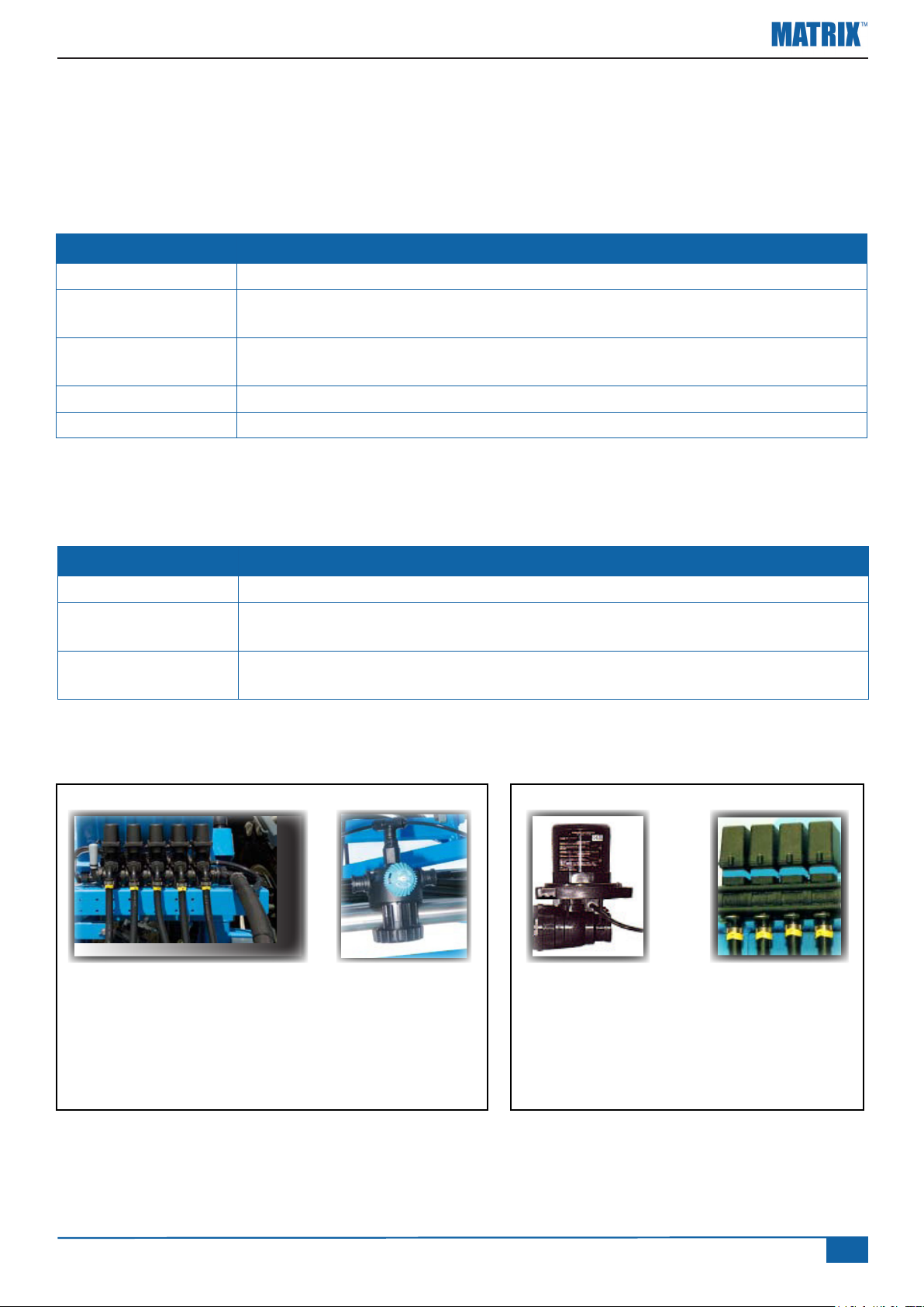
NEW SAFI PNEUMATIC OLD SAFI ARAG
- 3 wire connection
- Permanent 12V and Gnd
- Switching input 12V = ON
CL230 Guidance controller kit
Berthoud TELEVOLUX ABSC kit, for ‘New Sa’ or ‘Pneumatic’ valve type
(Pos. 3-6 /System Overview)
Berthoud TELEVOLUX ABSC kit, for ‘Old Sa’ or ‘ARAG’ valve type
(Pos. 3-5 /System Overview)
- 2 wire connection
- Permanent Gnd
- 3 wire connection
- Permanent Gnd
- 2 Switching input
1. 12V = ON
- 2 wire connection
- Changeover polarity to
open and close
Kit no. 990-898 Kit no. 990-899
www.teejet.com
3
Page 4
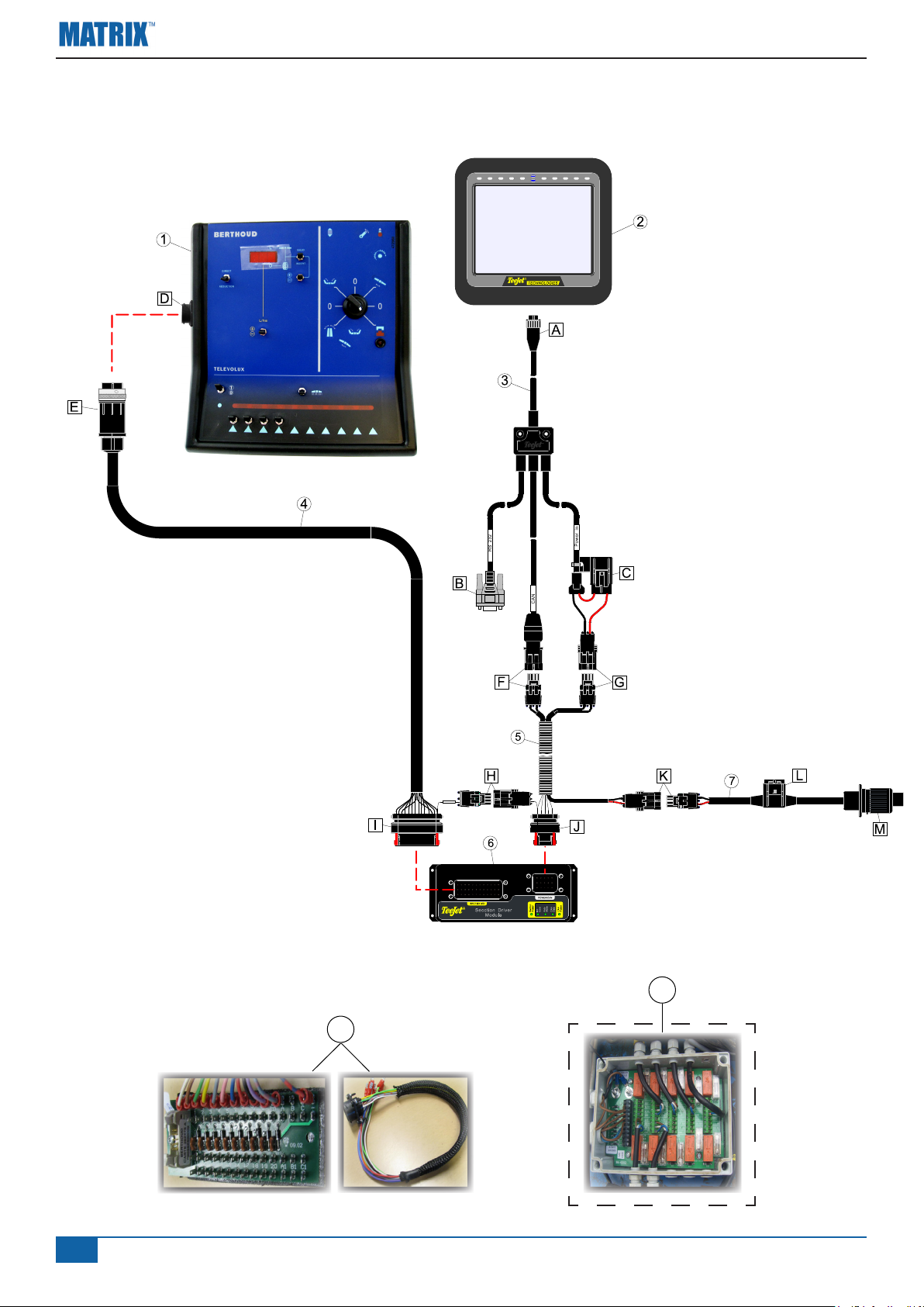
SYSTEM OVERVIEW, MATRIX
TM
1008-0203
A B
A
Section Power
BBA
BA
9
8
4
www.teejet.com
Page 5
SYSTEM DESCRIPTION, MATRIX
TM
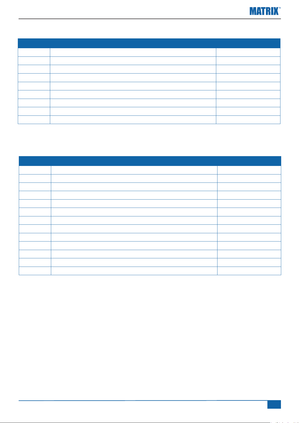
Pos. Description Part Number
1 Berthoud TELEVOLUX Switch Box 2 MATRIX
3 Power/CAN/Data Cable, MATRIX
TM
Guidance Controller * xxx-xxx
TM
45-05626
4 BoomPilot cable (Sections) 198-417
5 BoomPilot cable (CANBUS & Power) 198-413
6 Section Driver Module 78-05072
7 Power Cable, w/COBO connector 45-05648
8 Berthoud ABSC Interface 902-422
9 Relay box ** 902-356
* Depending on MATRIX
Only kit no. 990-899 for ‘OLD SAFI’ & ‘ARAG’ valves
**
TM
Kit,
Connectors and fuses:
Pos. Description Part Number
A 8P Connector (Power/CAN/Data to Matrix)
B 9P Connector (Data in/out, Sub.D. Female)
C Fuse (3A) 166-603
D 19P connector, from the Berthoud ABSC interface
E 19P connector, BoomPilot cable
F 4P Connector (CAN, Matrix and Section Driver Module)
G 2P Connector (Power to Matrix Controller)
H 2P connector, section power
I 35P Connector (Boom Section I/O to Section Driver Module)
J 14P connector, SDM module
K 2P Connector (System Power)
L Fuse (3A) 39-00000
M 3P COBO connector
www.teejet.com
5
Page 6
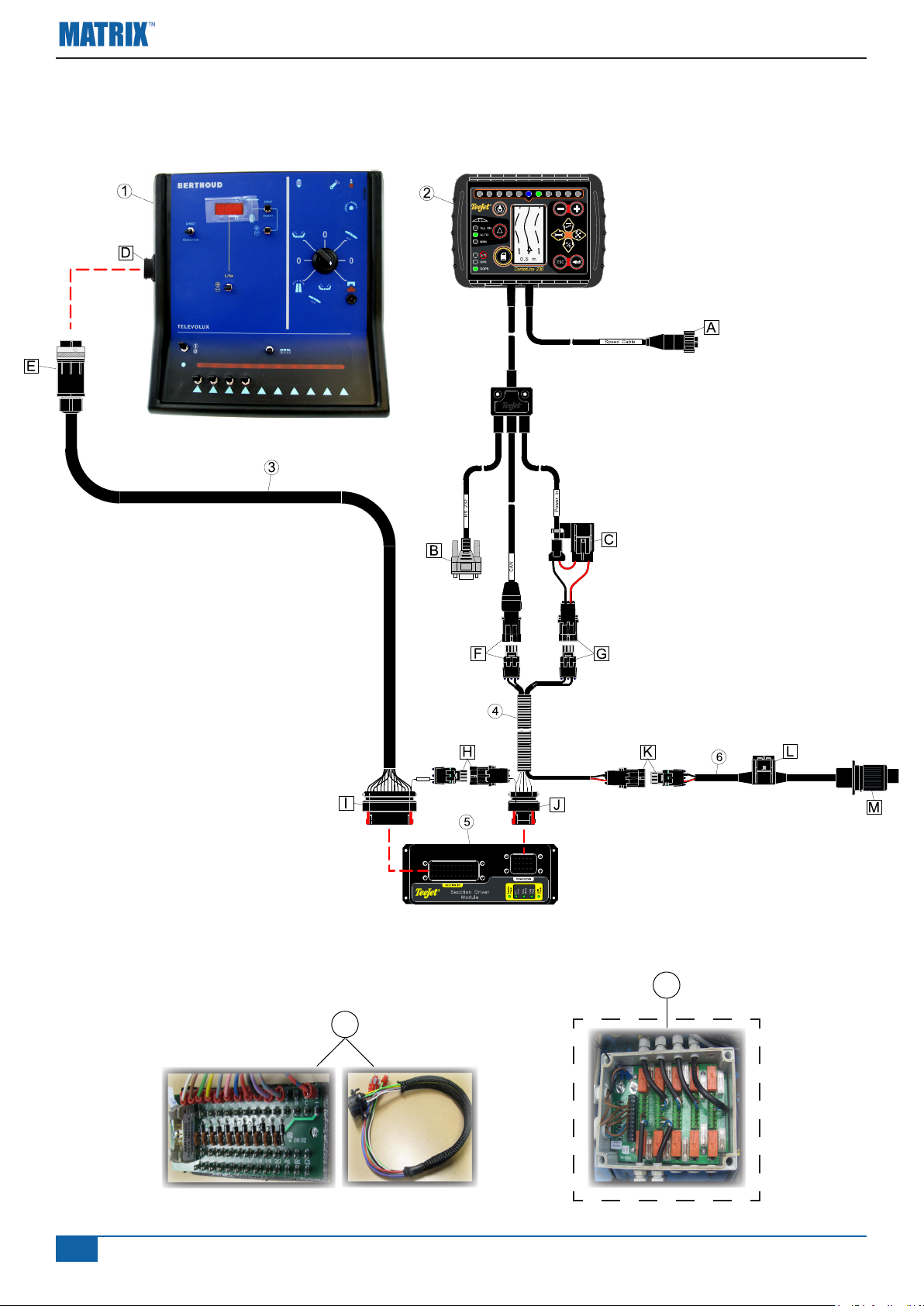
SYSTEM OVERVIEW, CL230
1008-0203
A B
A
Section Power
BBA
BA
8
7
6
www.teejet.com
Page 7
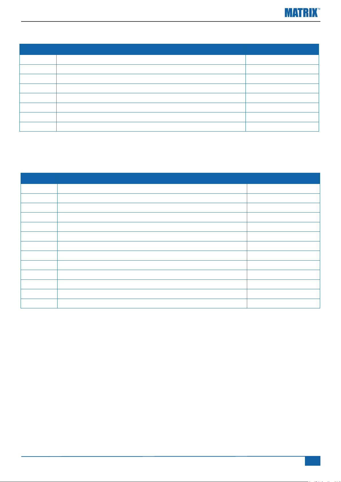
SYSTEM DESCRIPTION, CL230
Pos. Description Part Number
1 Berthoud TELEVOLUX Switch Box 2 CL230 Guidance Controller * xxx-xxx
3 BoomPilot cable (Sections) 198-417
4 BoomPilot cable (CANBUS & Power) 198-413
5 Section Driver Module 78-05072
6 Power Cable, w/COBO connector 45-05648
7 Berthoud ABSC Interface 902-422
8 Relay box ** 902-356
* Depending on CL230 Kit,
Only kit no. 990-899 for ‘OLD SAFI’ & ‘ARAG’ valves
**
Connectors and fuses:
Pos. Description Part Number
A 4P connector, speed output
B 9P Connector (Data in/out, Sub.D. Female)
C Fuse (3A) 166-603
D 19P connector, from the Berthoud ABSC interface
E 19P connector, BoomPilot cable
F 4P Connector (CAN, Matrix and Section Driver Module)
G 2P Connector (Power to Matrix Controller)
H 2P connector, section power
I 35P Connector (Boom Section I/O to Section Driver Module)
J 14P connector, SDM module
K 2P Connector (System Power)
L Fuse (3A) 39-00000
M 3P COBO connector
www.teejet.com
7
Page 8
INSTALLING THE BERTHOUD TELEVOLUX KIT
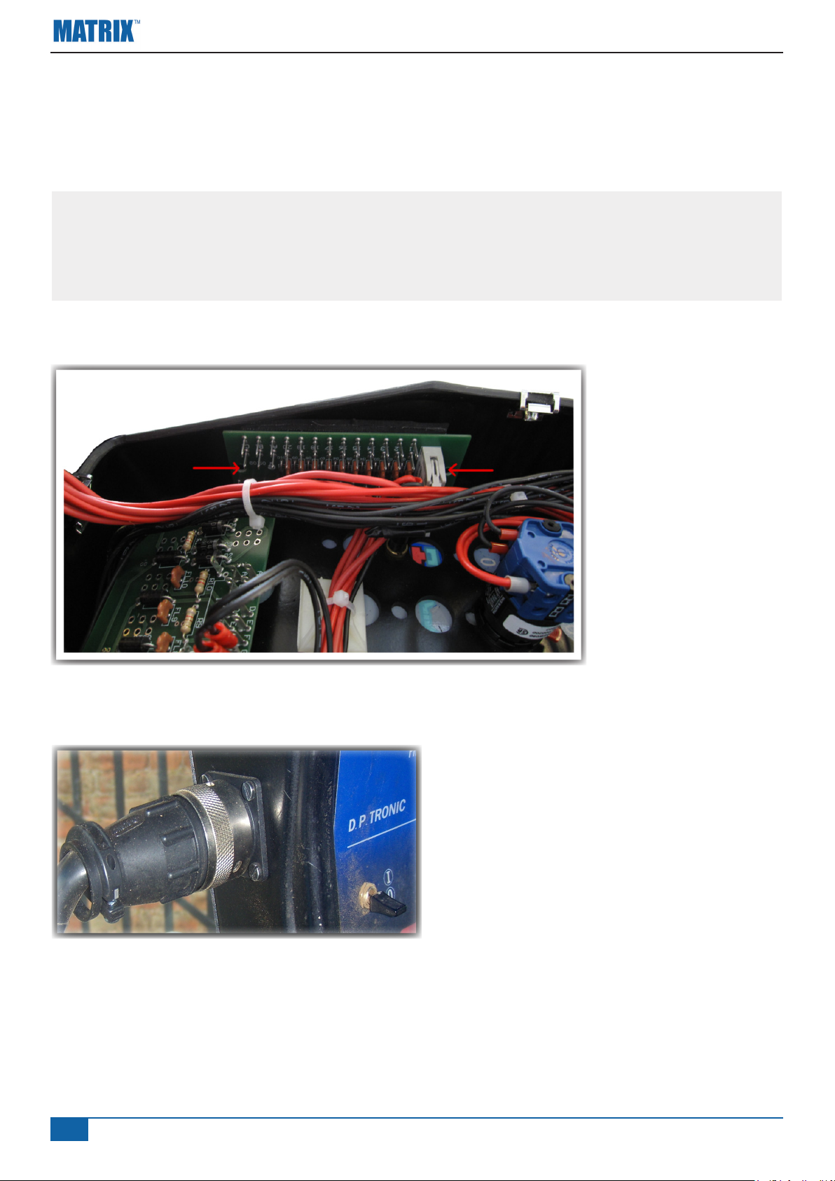
To get electrical contact with the Sections and the Master switch in the Berthoud TELEVOLUX
Switch Box, it’s necessary to install a Berthoud ABSC Interface (See pos. 7 and 8 on the two System
Overview drawings). Before starting the installation, make sure that the power is disconnected.
This is a critical operation and must only be conducted of persons with the
necessary skills. In case the Berthoud TELELUX Switch Box is damaged during
the installation, it's on the buyers sole risk and therefore the buyer is not entitled
to any form for compensation.
Installing the Interface Circuit board:
Place the interface in
the right part of the box
as shown on the picture.
Drill two ø3.5 mm holes
in the plastic housing
with a distance of 95
mm.
It’s practical to install the wires on the interface before installing it (See diagram next page).
Installing the Connector:
Make a hole in the left part of the plastic
housing and install the round connector. The
Hole should be ø25 mm and xing holes ø3.2
mm.
Connect the Automatic Boom section kit as show on the system overview drawings. The kit includes
all necessary connectors to get electrical contact with the Berthoud TELEVOLUX Switch Box.
8
www.teejet.com
Page 9
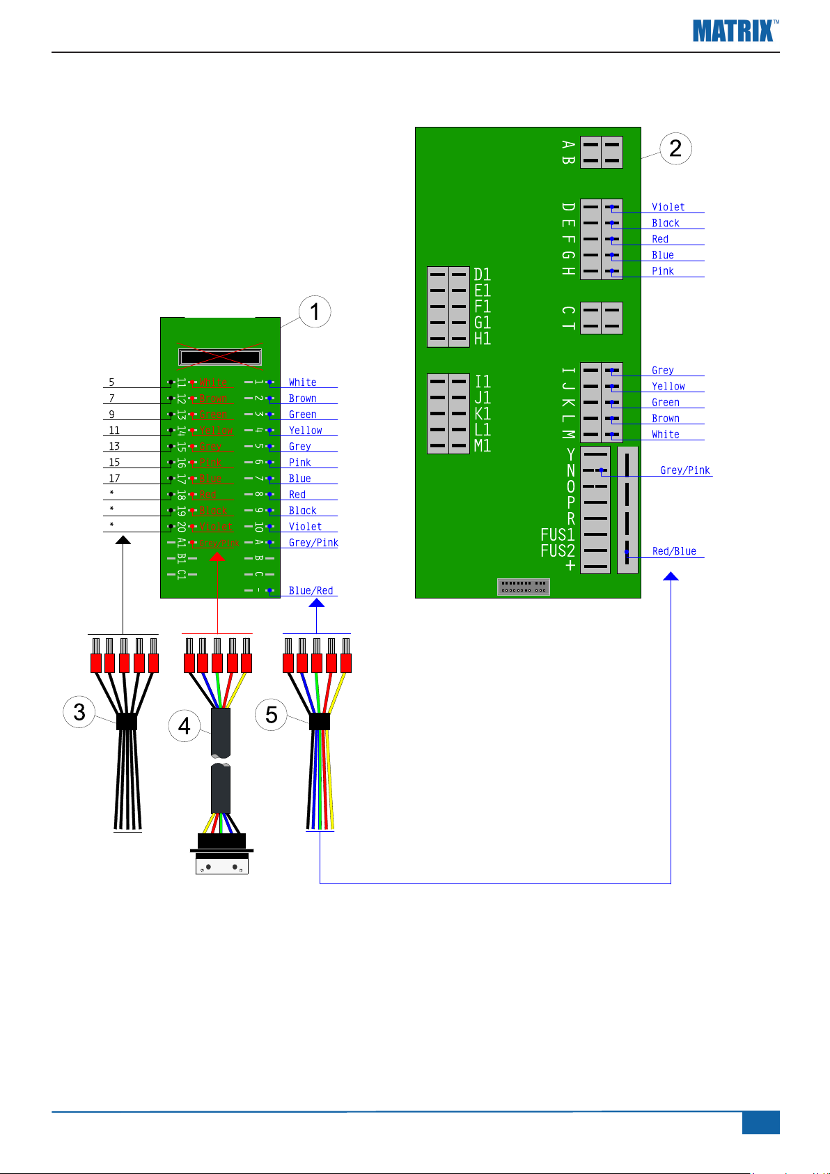
WIRING DIAGRAM
Carte pulve
1. Connect the external connector cable (4) to the interface (1), in the middle row.
2. Disconnect the wires (3) from the "Carte Pulvé" board (2) and connect them to the interface (1).
3. Connect the wires (5) to the interface (1) and to the “Carte Pulve” board (2).
www.teejet.com
9
Page 10
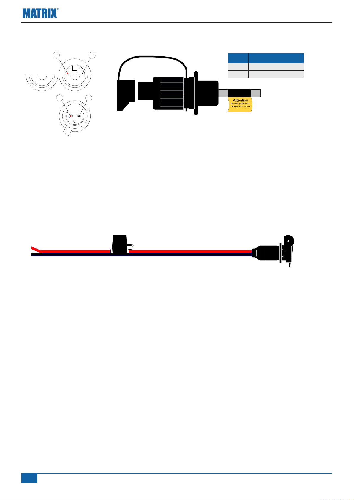
CONNECTING POS. M TO POWER
1
+
1
15/30
2
-
POS DESCRIPTION
1 +12V (15/30)
2 Ground (31)
2
31
82
! When connecting the system to 12V
power it's very important that the polarity
is correct, if not the system will be
damaged.
BATTERY CABLE (OPTION):
The power supply must be strong enough to operate the Section and Master valves. The total current will depend on the used valve type.
If a power connector (Socket) isn't available in the tractor cabin, a optional battery cable can be
used (PN 96ET14).
10
www.teejet.com
Page 11
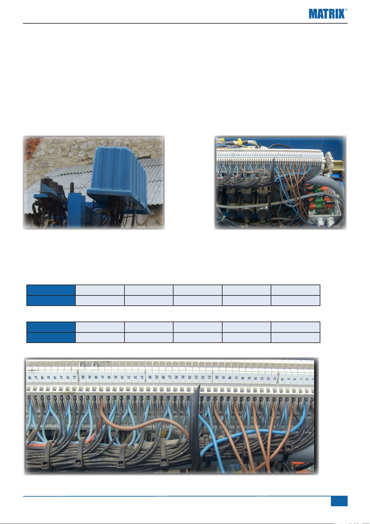
VALVES CONNECTION
Berthoud sprayers with New Sa or pneumatic valves:
- No particular connection has to be done. Original cabling is ok.
Berthoud sprayers with Old Sa or Arag valves:
- Relay box installation
Take out the blue cover above the boom
Fix the relay box to the frame
Driving wires connection to relay box
Connect loose wires to the connection bloc. Below a informative table but verify that the
respective connections are giving out 12 V when section is ON.
Name S1 S2 S3 S4 S5
Pin 8 11 14 17 20
Name S6 S7 S8 GND 12V
Pin 23 27 30 6 37
www.teejet.com
11
Page 12
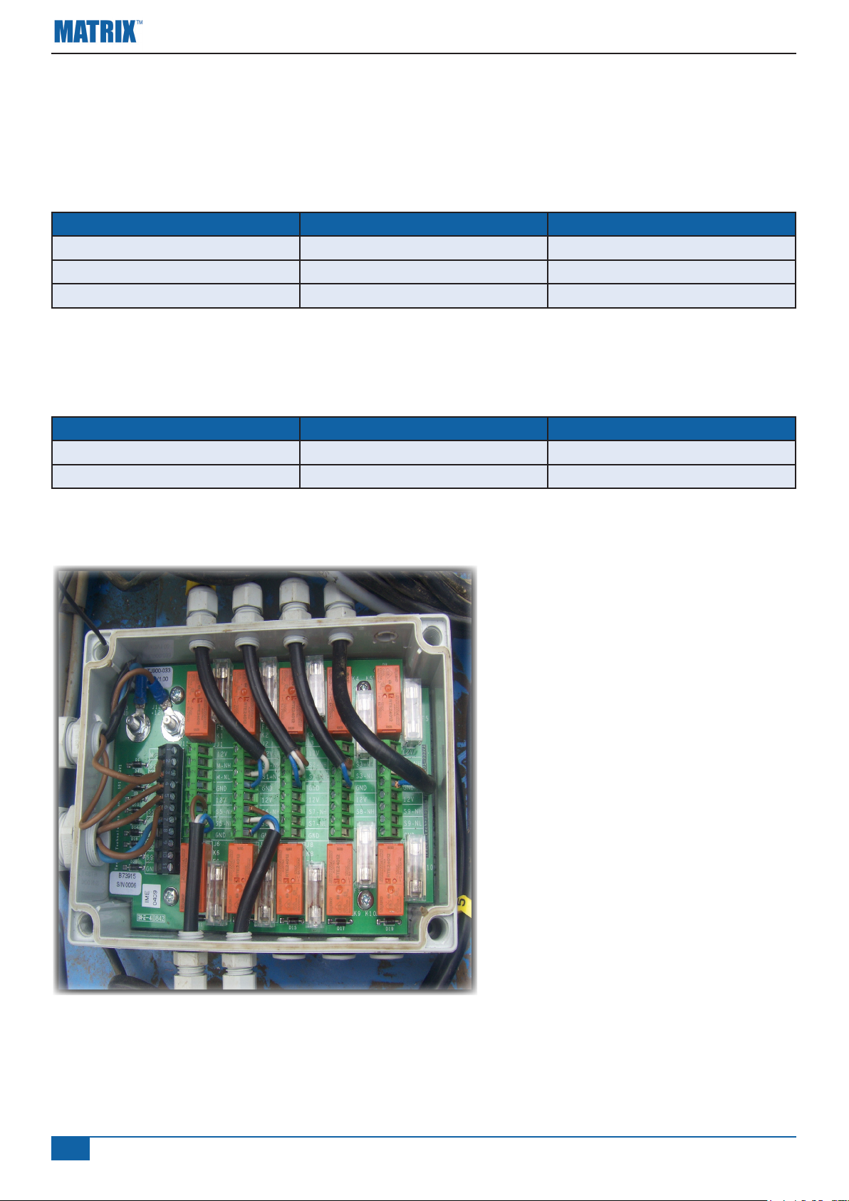
Valves connections to relay box
Disconnect the valves from the connection bloc and connect them into the relay box.
For old SAFI valves:
Wire Color Connection Function
Brown NH 12 V for closing
White NL 12 V for opening
Blue GND Permanent Ground
For ARAG valves:
Wire Color Connection Function
Brown NH 12 V for closing
Blue NL 12 V for opening
12
www.teejet.com
Page 13
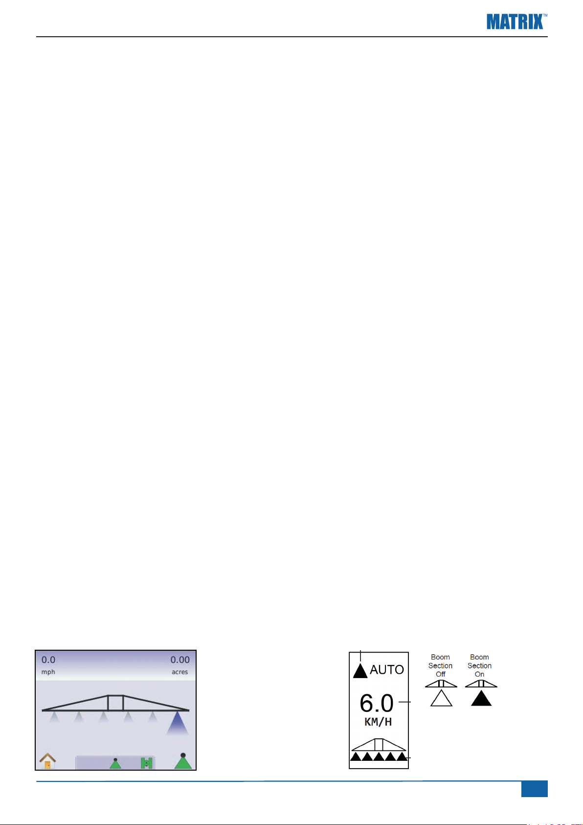
SYSTEM CHECK
After connecting the power connector, it's time to make a system check. To check the system it's
necessary to have full GPS signal so the vehicle must be placed outside.
Check AUTO mode:
Berthoud TELEVOLUX:
• Section switches should be in OFF position when working in Automatic mode.
• The Master switch will control the sprayer and should be ON to enable automatic switching of
the sections.
MATRIXTM or CL230:
• Turn the Guidance controller on
• Encode the number of sections and the width of each
(Refer to the MATRIXTM or CL230 user manual)
• Wait for GPS signal
• Set the mode to AUTO
• Drive forward (> 2 km/h)
• Observe that all sections and the master valve open.
• Check that the Master valve closes when the Master switch is set off.
Check MANUAL mode:
MATRIXTM or CL230:
• Set the ABSC mode to MANUAL
Check in the ‘Boom Section Control Screen’ (Matrix or CL230) that the section icons turn off and
on according to the valve/switch status.
Berthoud TELEVOLUX:
• Set the section switch's on
• Set the Master switch on
• Observe that all sections and the master valve open.
MATRIXTM: CL230:
www.teejet.com
13
Page 14
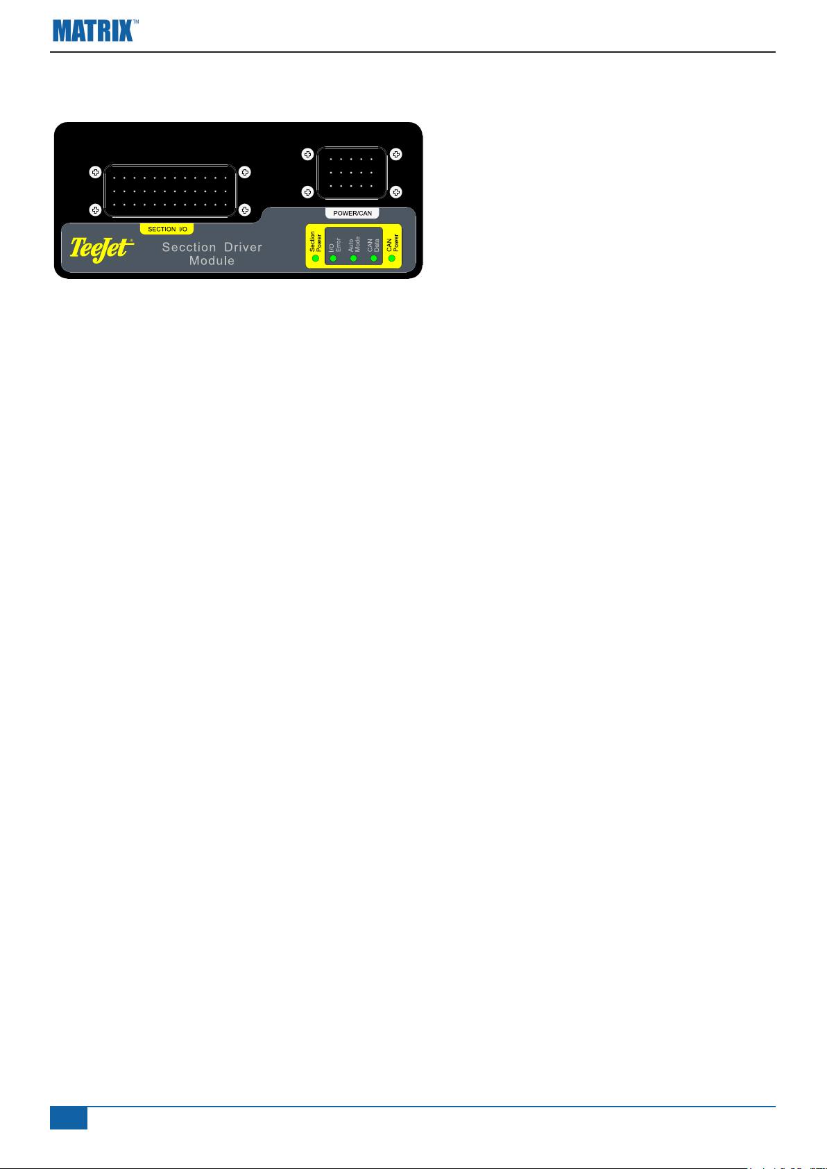
LED’S ON THE SECTION DRIVER MODULE
Section Power: ON when power is available for the section drivers.
I/O error: Should normally be OFF
(Auto Mode: ON when automatic boom switching is active).
CAN Data: ON is ashing when it communicates with the CenterLine 230.
CAN Power: ON when power is applied to the CenterLine 230 and the SDM.
14
www.teejet.com
Page 15

www.teejet.com
15
Page 16

I N S T A L L A T I O N M A N U A L
Matrix Guidance: Exclusive Features
• RealView™ Guidance Over Video
◄GuidanceSuperimposedOverVideo
◄GuidanceOnly
◄VideoOnly
• BrightDaylightReadableScreen
• Easy-to-Use3DGraphicalGuidance
• CoverageMapping/DataExport
Mølhavevej 2
9440 Aabybro
Denmark
Tel: +45 96962500
Fax: +45 96962501
www.teejet.com
020-047-UK R1
© TeeJet Technologies 2009
 Loading...