

BOOMPILOT®
INSTALLATION MANUAL
Automatic boom section control installation manual
for use with Amazone Amatron+ & Amatron 3
controllers w/Matrix® Pro

Copyrights
© 2014 TeeJet Technologies. All rights reserved. No part of this document or the computer programs described in it may be reproduced,
copied, photocopied, translated, or reduced in any form or by any means, electronic or machine readable, recording or otherwise, without
prior written consent from TeeJet Technologies.
Trademarks
Unless otherwise noted, all other brand or product names are trademarks or registered trademarks of their respective companies or
organizations.
Limitation of Liability
TEEJET TECHNOLOGIES PROVIDES THIS MATERIAL “AS IS” WITHOUT WARRANTY OF ANY KIND, EITHER EXPRESSED OR
IMPLIED. NO COPYRIGHT LIABILITY OR PATENT IS ASSUMED. IN NO EVENT SHALL TEEJET TECHNOLOGIES BE LIABLE FOR ANY
LOSS OF BUSINESS, LOSS OF PROFIT, LOSS OF USE OR DATA, INTERRUPTION OF BUSINESS, OR FOR INDIRECT, SPECIAL,
INCIDENTAL, OR CONSEQUENTIAL DAMAGES OF ANY KIND, EVEN IF TEEJET TECHNOLOGIES HAS BEEN ADVISED OF SUCH
DAMAGES ARISING FROM TEEJET TECHNOLOGIES SOFTWARE.
Safety Information
TeeJet Technologies is not responsible for damage or physical harm caused by failure to adhere to the following safety
requirements.
As the operator of the vehicle, you are responsible for its safe operation.
The BoomPilot is not designed to replace the vehicle’s operator.
Do not leave a vehicle while the BoomPilot is engaged.
Be sure that the area around the vehicle is clear of people and obstacles before and during engagement.
The BoomPilot is designed to support and improve efciency while working in the eld. The driver has full responsibility for the quality and
work related results.
Disengage BoomPilot before operating on public roads or when not in use to prevent loss of vehicle control.

1
98-05328-EN
BoomPilot
®
Table of contents
INTRODUCTION TO MATRIX PRO GS - BOOMPILOT 2
Principle of operation ........................................................................................................................................................2
Features ...............................................................................................................................................................................2
Software version .................................................................................................................................................................2
REQUIRED COMPONENTS 2
INSTALLATION 5
1. CONSOLE ............................................................................................................................................................................................................ 5
2. ANTENNA ............................................................................................................................................................................................................ 5
3. BOOMPILOT INTERFACE ............................................................................................................................................................................... 6
4. CAN/POWER/DATA CABLE & CAN TERMINATION............................................................................................................................... 6
5. POWER ................................................................................................................................................................................................................. 7
Optional Battery Cable ...................................................................................................................................................................7
6. COMPLETE ELECTRONIC INSTALLATION ............................................................................................................................................... 7
TRANSPORT MODE NOTES 8
SYSTEM CHECK 9
Amatron .................................................................................................................................................................................9
Matrix Pro GS ........................................................................................................................................................................9
2
www.teejet.com
BoomPilot
®
INTRODUCTION TO MATRIX PRO GS - BOOMPILOT
Principle of operation
The Matrix Pro GS controls the sprayer according to the GPS
position as well as the GPS guidance to avoid overlaps or skips. The
Matrix Pro GS controls the sprayer in automatic mode and monitor
the sprayer in manual mode. The operator is always able to override
the control of the sprayer via the master key on the Amatron rate
controller.
Features
The Matrix Pro GS and the Amazone BoomPilot interface, in
combination with Amatron+ or Amatron-3, adds ‘Automatic boom
section control’ to Amazone sprayers.
Software version
The Amatron and the Matrix Pro GS communicates via a special
interface using the Amaclick CAN bus protocol. The software version
in the Amazone job-computer must be v7.07.16 or higher. If the
job-computer software is older than 7.07.12, please contact your
Amazone dealer.
NOTE: Messages on AMABUS system as to if the BOOM/TOWER
is active/inactive while in the transport position were not
implemented prior to version 7.07.12.
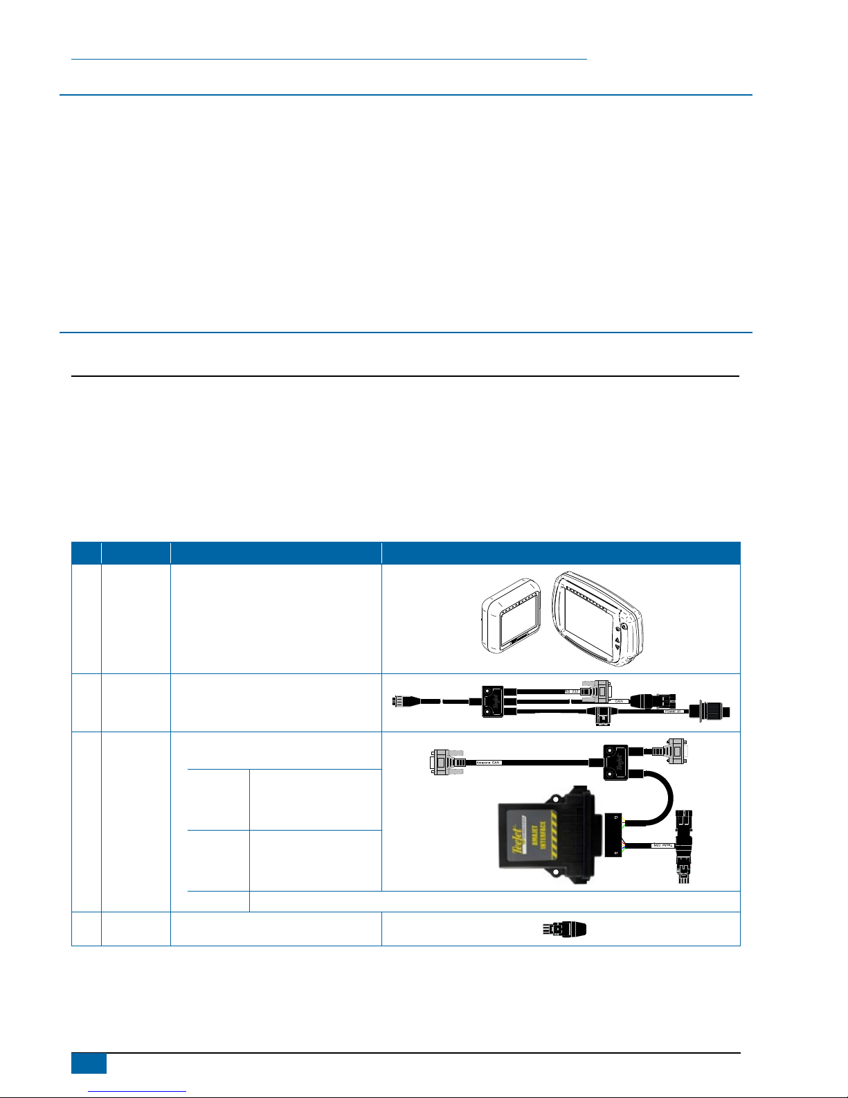
REQUIRED COMPONENTS
Unpack the installation kit and identify the required parts for your installation.
Item Part Number Description Quantity
A 90-xxxxx* Matrix Pro GS guidance controller kit ..............................................................................................................................1
B 45-05826 Power/CAN/Data cable w/COBO connector ....................................................................................................................1
C 90-02883 Amatron+ / Amatron-3 BoomPilot interface with harness. ...............................................................................................1
45-05919 Harness, Amazone Interface .......................................................................................................................................1
78-05108 Interface, Amazone BoomPilot ....................................................................................................................................1
98-05328 Installation manual, Amazone Amatron+ / Amatron-3 Controller .................................................................................1
D 45-08101 CAN bus termination ........................................................................................................................................................1
*Part number is dependent on kit contents
Item Part # Description Illustration
A
Part
number is
dependent
on kit
contents
Matrix Pro GS guidance controller kit
Matrix Pro 570G
Matrix Pro 840G
B 45-05826
Power/CAN/data cable w/COBO
connector.
C 90-02883
Amatron+ / Amatron-3 BoomPilot
Interface with harness.
45-05919
Harness, Amazone
Interface
78-05108
Interface, Amazone
BoomPilot
98-05328 Installation manual, Amazone- Amatron+ / Amatron-3 Controller.
D 45-08101 CAN bus termination.

3
98-05328-EN
BoomPilot
®
The Amazone system can include a joy-stick or/and a Amaclick switch box, so your system may vary from the system overview drawing, see
the possible combinations on the next page.
Figure 1: System diagram
Power
Amazone
Power
Matrix
Matrix
BoomPilot Interface
CAN <> CAN
Amatron+ / Amatron-3
Amazone Job-computer
1008-0276
A B

4
www.teejet.com
BoomPilot
®
The TeeJet BoomPilot interface communicates with the Amatron via the Amaclick protocol using the same CAN bus-id. The Amaclick
and the BoomPilot interface cannot be connected at the same time.
AMACLICK is an optional ergonomic CAN bus switch box, typical used in special crops which often require manual on/off control of the
individual sections. When the BoomPilot interface is connected, manual on/off control of the individual sections must be done via the joy-stick
or Amatron.
Figure 2: Possible combinations
Amatron+
Amatron-3
TeeJet BoomPilot
Interface
Amatron+
Amatron-3
TeeJet BoomPilot
Interface
Amazone
Joy-stick
Amatron+
Amatron-3
TeeJet BoomPilot
Interface
Amazone
Amaclick
Amatron+
Amatron-3
TeeJet BoomPilot
Interface
Amazone
Joy-stick
Amazone
Amaclick
A
B
C
D

5
98-05328-EN
BoomPilot
®
INSTALLATION
If there are questions concerning the installation of the BoomPilot system on this vehicle, or due to the changes in component
specications the parts supplied in the kit are not exactly as presented in this document, please contact your dealer or TeeJet
Customer service representative for clarication before installation. TeeJet Technologies is not responsible for misuse or incorrect
installation of the system.
NOTE: All references to left and right are stated as if the user is seated in the driver’s seat.
NOTE: BE VERY CAREFUL TO ABSOLUTELY SECURE ALL CABLES THAT THEY DON’T INTERFERE WITH THE MANY MOVING PARTS
OF THE MACHINE.
1. CONSOLE
A secure, mechanical mounting solution needs to be employed for permanent mounts within an operating vehicle.
Figure 3: Recommended console placement
Console
2. ANTENNA
The GPS Antenna base is magnetic. Position the antenna in the centre of the vehicle at the highest point with a clear view of the sky. A metal
plate with adhesive strips has been included in the kit for easy mounting and installation.
Figure 4: Antenna placement
Centre of Plate
Centre of Vehicle
GPS
It is STRONGLY recommended to use this metal plate underneath the antenna as it will improve signal acquisition. Once the
antenna has been positioned, route the antenna cable carefully to avoid damage.

6
www.teejet.com
BoomPilot
®
3. BOOMPILOT INTERFACE
Connect the BoomPilot interface cable to the Amazone CAN bus, as
the last item before the Amatron controller.
Figure 5: BoomPilot interface cable to the Amazone CAN bus
BoomPilot Interface
CAN <> CAN
Amatron+ / Amatron-3
A B
Amatron CAN bus
4. CAN/POWER/DATA CABLE & CAN
TERMINATION
Connect the BoomPilot interface cable to the TeeJet CAN bus via the
CAN/Power/Data cable. The CAN bus termination ends the CAN bus.
The TeeJet system can include other CAN bus modules like camera
selector module or similar, so the your system may vary from the
picture shown in the example.
Figure 6: CAN/Power/data cable & CAN termination
Power
Matrix
Matrix
BoomPilot Interface
CAN <> CAN
A B

7
98-05328-EN
BoomPilot
®
5. POWER
Connect the Matrix Pro GS to constant power via the 3P connector (Only the big pins no. 15/30 and no. 31 are used).
Warning: When connecting the system to 12V power it’s very important that the polarity is correct, if not the system will be damaged.
+
-
15/30
82
31
+12V (15/30) +12V (15/30) Ground (31)Ground (31)
Pos. Description
1 +12V (15/30)
2 Ground (31)
Optional Battery Cable
If your tractor doesn’t support two power sockets, TeeJet offer an ‘Y-Power cable’, PN 198-332 (Contact your TeeJet dealer).
6. COMPLETE ELECTRONIC INSTALLATION
Refer to the Matrix Pro GS BoomPilot Setup in the full user manual for further instructions on setting up and using your Matrix Pro GS for
automatic boom section control.
If not using a Matrix Pro GS, please refer to the owner’s manual supplied with the guidance system to complete the electronic installation
and setup.

8
www.teejet.com
BoomPilot
®
TRANSPORT MODE NOTES
When in transport mode with the boom locked and tower locked, all jobs on the Matrix Pro GS console should be closed.
Figure 7: Amatron work screen with boom locked and tower locked

9
98-05328-EN
BoomPilot
®
SYSTEM CHECK
After connecting to power, it is time to make a system check. To check the system, it is necessary to have full GPS signal, the vehicle must be
placed outside.
Amatron
Refer to the Amatron setup guide for further instructions on setting up
the Amatron, if not already done.
1. Turn on the Amatron. It’s important the Amatron is turned on
before the Matrix Pro GS.
2. Unfold the boom so the Amatron is unlocked.
3. Select the work screen.
Matrix Pro GS
Refer to the Matrix Pro GS user manual for further instructions on
setting up and using your Matrix Pro GS for automatic boom section
control.
1. Turn on the Matrix Pro GS console.
2. Encode the number of sections and the width of each and other
necessary settings like distance from antenna to boom, overlap%
etc.
3. Wait for GPS signal and start a new job.
4. Set the BoomPilot mode to AUTOMATIC (Press the
icon).
◄Matrix Pro GS status bar Icon will change to green
.
◄Amatron manual boom section keys on the work screen will
disappear
Figure 8: Automatic to all booms on mode
7,2
km/h
2,07
ha
> 0,0 <
A
A
Figure 9: Amatron work screen,
when the Matrix Pro GS is in MANUAL mode
Figure 10: Amatron work screen
when the Matrix Pro GS is in AUTO mode
5. Drive forward (> 1.2 km/h).
6. Observe that all boom section valves open and the boom
indication in the Matrix Pro GS shows ON (White)
7. Check that the valves close when the master key is set to OFF
in the Amatron, or by spraying over an applied area, check the
boom indication in the Matrix Pro GS, shows OFF (Transparent).

BOOMPILOT
®
INSTALLATION MANUAL
TeeJet Aabybro
Mølhavevej 2
DK 9440 Aabybro
Danmark
www.teejet.com
A series of equipment-specic installation kits have been developed to work
in conjunction with your automated boom section control system. This kit
contains the necessary components and instructions to install BoomPilot
on a Amazone Amatron+ / Amatron-3 controller. Please review this manual
thoroughly before beginning the installation process.
98-05328-EN-A4 R0 English
© TeeJet Technologies 2014
 Loading...