

TeeJet Technologies Aeros 9040 User Manual
AEROS 9040
USER MANUAL
Software version 4.31

Copyrights
© 2017 TeeJet Technologies. All rights reserved. No part of this document or the computer programs described in it may be reproduced, copied,
photocopied, translated, or reduced in any form or by any means, electronic or machine readable, recording or otherwise, without prior written
consent from TeeJet Technologies.
Trademarks
Unless otherwise noted, all other brand or product names are trademarks or registered trademarks of their respective companies or organizations.
Limitation of liability
TEEJET TECHNOLOGIES PROVIDES THIS MATERIAL “AS IS” WITHOUT WARRANTY OF ANY KIND, EITHER EXPRESSED OR IMPLIED.
NO COPYRIGHT LIABILITY OR PATENT IS ASSUMED. IN NO EVENT SHALL TEEJET TECHNOLOGIES BE LIABLE FOR ANY LOSS OF
BUSINESS, LOSS OF PROFIT, LOSS OF USE OR DATA, INTERRUPTION OF BUSINESS, OR FOR INDIRECT, SPECIAL, INCIDENTAL, OR
CONSEQUENTIAL DAMAGES OF ANY KIND, EVEN IF TEEJET TECHNOLOGIES HAS BEEN ADVISED OF SUCH DAMAGES ARISING FROM
TEEJET TECHNOLOGIES SOFTWARE.
Safety information
TeeJet Technologies is not responsible for damage or physical harm caused by failure to adhere to the following safety requirements.
As the operator of the vehicle, you are responsible for its safe operation.
The Aeros 9040 in combination with any assisted/auto steering device is not designed to replace the vehicle’s operator.
Do not leave a vehicle while the Aeros 9040 is engaged.
Be sure that the area around the vehicle is clear of people and obstacles before and during engagement.
The Aeros 9040 is designed to support and improve efciency while working in the eld. The driver has full responsibility for the quality and work
related results.
Disengage or remove any assisted/auto steering device before operating on public roads.
Aeros 9040 eld computer
Table of contents
CHAPTER 1 INTRODUCTION 1
Product upgrades available ........................................................................................................................................................................1
SYSTEM COMPONENTS 1
Aeros 9040 console ........................................................................................................................................................................................1
Buttons .....................................................................................................................................................................2
RealView® camera ...........................................................................................................................................................................................2
Additional information .................................................................................................................................................................................2
BASIC SCREEN USE 3
Bottom tab keys ........................................................................................................................................................3
Unavailable options when job is active ......................................................................................................................3
Console screen colours .............................................................................................................................................4
Simple or advanced mode .........................................................................................................................................4
Warnings and information pop-ups ............................................................................................................................5
Setup option information ...........................................................................................................................................5
Drop-down menu selections ......................................................................................................................................5
Scrolling screens .......................................................................................................................................................5
Keyboard entry screen ..............................................................................................................................................6
Next page .................................................................................................................................................................6
Checkboxes ..............................................................................................................................................................6
HOMESETUPGUIDANCE FULL SCREENIMPLEMENT INTRODUCTIONGNSSRATE CONTROLAPPENDIX
CHAPTER 2 JOBS / HOME SCREEN 7
Simple mode .............................................................................................................................................................7
Advanced mode ........................................................................................................................................................7
SIMPLE MODE 8
New job ..............................................................................................................................................................................................................8
Continue job .....................................................................................................................................................................................................8
Close job ............................................................................................................................................................................................................8
ADVANCED MODE 8
New job ..............................................................................................................................................................................................................8
Start job .............................................................................................................................................................................................................. 8
Close job ............................................................................................................................................................................................................8
CHAPTER 3 FULL SCREEN VIDEO VIEW 9
Camera snapshot ......................................................................................................................................................................................... 10
VSM camera options ................................................................................................................................................................................... 10
CHAPTER 4 SYSTEM SETUP 11
Overview ......................................................................................................................................................................................................... 11
98-05304-EN R2
i
Aeros 9040 eld computer
CONFIGURATION 12
Implement ...................................................................................................................................................................................................... 13
Single section setup ...............................................................................................................................................13
Section(s) with ISOBUS sprayer/spreader setup ......................................................................................................14
Multiple sections with SDM/SFM setup ....................................................................................................................15
Droplet size monitor ................................................................................................................................................16
HOME SETUP GUIDANCEFULL SCREEN IMPLEMENTINTRODUCTION GNSS RATE CONTROL APPENDIX
Nozzle selection ......................................................................................................................................................16
Reverse sense options ............................................................................................................................................17
Mapping and guidance ............................................................................................................................................................................. 17
Mapping and guidance [console only] ......................................................................................................................17
Mapping and guidance using an external lightbar ....................................................................................................18
User entered mapping location ................................................................................................................................19
GNSS ................................................................................................................................................................................................................. 20
Video ................................................................................................................................................................................................................ 21
Sensors ............................................................................................................................................................................................................ 21
Input/output module pressure sensor.......................................................................................................................22
Nozzle ow monitor ................................................................................................................................................................................... 23
ISOBUS ............................................................................................................................................................................................................. 23
Product ............................................................................................................................................................................................................ 24
AutoSteer ........................................................................................................................................................................................................ 25
FieldPilot [using a SCM] ..........................................................................................................................................25
FieldPilot Pro / UniPilot Pro [using a SCM Pro] ........................................................................................................25
Tilt correction ................................................................................................................................................................................................ 27
DATA MANAGEMENT 28
Job data ........................................................................................................................................................................................................... 28
Transfer ..................................................................................................................................................................29
Manage ...................................................................................................................................................................29
Reports ............................................................................................................................................................................................................ 31
Options (Job mode) .................................................................................................................................................................................... 32
Machine settings .......................................................................................................................................................................................... 33
Transfer ..................................................................................................................................................................33
Manage ...................................................................................................................................................................34
CONSOLE 35
About ............................................................................................................................................................................................................... 35
Display ............................................................................................................................................................................................................. 36
Cultural ............................................................................................................................................................................................................ 36
Audio volume ................................................................................................................................................................................................ 37
Demo GNSS ................................................................................................................................................................................................... 37
Restart Demo GNSS ...............................................................................................................................................38
Feature unlock .............................................................................................................................................................................................. 38
TOOLS 39
Upload software ........................................................................................................................................................................................... 39
Extras ................................................................................................................................................................................................................ 40
ii
www.teejet.com
Aeros 9040 eld computer
CHAPTER 5 GNSS RECEIVER CONFIGURATION 41
GNSS ................................................................................................................................................................................................................. 41
GNSS type ..............................................................................................................................................................42
GNSS port...............................................................................................................................................................42
Programme .............................................................................................................................................................44
PRN ....................................................................................................................................................................... 44
Show refresh GNSS position button ........................................................................................................................45
GNSS glossary ............................................................................................................................................................................................... 45
CHAPTER 6 IMPLEMENT SETUP 47
Multiple section output modules .......................................................................................................................................................... 47
IMPLEMENT TYPE 48
Section numbers .....................................................................................................................................................48
Straight ............................................................................................................................................................................................................ 48
Single section .........................................................................................................................................................48
Multiple sections with SDM or SFM .........................................................................................................................49
Multiple sections with ISOBUS sprayer setup ..........................................................................................................50
Spreader – TeeJet ......................................................................................................................................................................................... 51
Single section .........................................................................................................................................................51
Multiple sections .....................................................................................................................................................52
Spreader – OEM ............................................................................................................................................................................................ 54
Single section .........................................................................................................................................................54
Multiple sections .....................................................................................................................................................54
Staggered ....................................................................................................................................................................................................... 55
Multiple sections .....................................................................................................................................................55
HOMESETUPGUIDANCE FULL SCREENIMPLEMENT INTRODUCTIONGNSSRATE CONTROLAPPENDIX
APPLICATION OR WORKING WIDTH 57
Single section .........................................................................................................................................................57
Multiple sections .....................................................................................................................................................57
ISOBUS SPRAYER OFFSETS 58
Self-propelled – front mount ....................................................................................................................................58
Self-propelled – rear mount .....................................................................................................................................59
Three point hitch – front mount ................................................................................................................................59
Three point hitch – rear mount ................................................................................................................................60
Trailed – always rear mount ....................................................................................................................................61
IMPLEMENT LATERAL OFFSET DISTANCE ADJUSTMENT 62
GNSS offset adjustment calculation.........................................................................................................................62
Implement lateral offset adjustment .........................................................................................................................63
REVERSE SENSE 64
Reverse on guidance screens .................................................................................................................................64
NOZZLE SELECTION 65
Preset .....................................................................................................................................................................65
Current nozzle .........................................................................................................................................................66
98-05304-EN R2
iii
Aeros 9040 eld computer
DROPLET SIZE MONITOR 66
Setup ................................................................................................................................................................................................................ 66
Enable/disable DSM ................................................................................................................................................66
Nozzle selection / current nozzle .............................................................................................................................66
Input/output module pressure sensor.......................................................................................................................66
Operation ....................................................................................................................................................................................................... 67
HOME SETUP GUIDANCEFULL SCREEN IMPLEMENTINTRODUCTION GNSS RATE CONTROL APPENDIX
BOOMPILOT SECTION CONTROL 68
CHAPTER 7 GUIDANCE AND MAPPING 69
GUIDANCE BAR 74
Status bar ...............................................................................................................................................................67
Guidance bar ..........................................................................................................................................................67
Overview ......................................................................................................................................................................................................... 69
Screens options ............................................................................................................................................................................................ 70
Navigation activity & Boom status ...........................................................................................................................74
Selectable Information.............................................................................................................................................74
STATUS BAR 75
Status/information screens ...................................................................................................................................................................... 76
NAVIGATION SCREENS 78
Vehicleview ................................................................................................................................................................................................... 78
Fieldview ........................................................................................................................................................................................................ 79
RealView guidance ...................................................................................................................................................................................... 80
GUIDANCE MODES 81
Straight AB guidance.................................................................................................................................................................................. 81
Curved AB guidance ................................................................................................................................................................................... 81
Adaptive curve AB guidance ................................................................................................................................................................... 81
Circle pivot guidance ................................................................................................................................................................................. 81
Last pass guidance ...................................................................................................................................................................................... 81
NextRow guidance ...................................................................................................................................................................................... 82
No guidance .................................................................................................................................................................................................. 82
GUIDELINES 82
Marking A and B points ............................................................................................................................................................................. 82
A+ nudge feature ....................................................................................................................................................83
Next guideline feature ............................................................................................................................................................................... 84
Last pass guidelines .................................................................................................................................................................................... 84
NextRow guidelines .................................................................................................................................................................................... 85
Azimuth degree ........................................................................................................................................................................................... 85
RETURN TO POINT 86
Marking a return point .............................................................................................................................................86
Delete the return point .............................................................................................................................................86
Guidance to a return point .......................................................................................................................................86
iv
www.teejet.com
Aeros 9040 eld computer
BOOMPILOT 87
No Section control module ...................................................................................................................................................................... 87
ISOBUS sprayer ............................................................................................................................................................................................. 88
ISOBUS spreader .......................................................................................................................................................................................... 89
With TeeJet section control module and switchbox or ISM ......................................................................................................... 90
With TeeJet section control module ..................................................................................................................................................... 90
CURVED LOOKAHEAD 90
REFRESH GNSS POSITION 91
NOZZLE FAULT RESET 91
BOUNDARIES AND POLYGONS 92
Boundaries ..................................................................................................................................................................................................... 92
Establishing an exterior or interior boundary ...........................................................................................................92
Delete last marked boundary ...................................................................................................................................94
Boundary on status bar ...........................................................................................................................................94
Polygons ......................................................................................................................................................................................................... 94
Establishing a polygon ...........................................................................................................................................94
Delete last marked polygon .....................................................................................................................................95
MAPPING OPTIONS 96
Polygon mapping ........................................................................................................................................................................................ 96
Rate control mapping ................................................................................................................................................................................ 96
APPLICATION CONTROL OPTIONS 97
HOMESETUPGUIDANCE FULL SCREENIMPLEMENT INTRODUCTIONGNSSRATE CONTROLAPPENDIX
ZOOM IN/OUT 97
Vehicleview ................................................................................................................................................................................................... 97
Fieldview ........................................................................................................................................................................................................ 97
PAN MODE 98
REALVIEW SPECIFIC OPTIONS 98
RealView guidance options ..................................................................................................................................................................... 99
Camera snapshot ......................................................................................................................................................................................... 99
VSM camera options ................................................................................................................................................................................... 99
CHAPTER 8 RATE CONTROL 101
Ready for operation ..................................................................................................................................................................................102
ISOBUS configuration options ............................................................................................................................... 102
NAVIGATION SCREEN OPTIONS 103
Guidance bar ........................................................................................................................................................103
Current pressure ...................................................................................................................................................103
98-05304-EN R2
v

Aeros 9040 eld computer
Application control options ....................................................................................................................................103
Mapping options .................................................................................................................................................... 104
MAPPING OPTIONS 104
Coverage map .............................................................................................................................................................................................105
Polygons map .............................................................................................................................................................................................105
Prescription map ........................................................................................................................................................................................106
HOME SETUP GUIDANCEFULL SCREEN IMPLEMENTINTRODUCTION GNSS RATE CONTROL APPENDIX
Application and target rate maps .......................................................................................................................................................106
Application map ...................................................................................................................................................106
Target rate map ..................................................................................................................................................... 107
Colour range selection ..........................................................................................................................................107
APPENDIX A SYSTEM CONFIGURATIONS 109
APPENDIX B AEROS CONSOLE MENU SETTINGS 112
APPENDIX C UNIT SPECIFICATIONS 116
APPENDIX D SETTING RANGES 116
APPENDIX E UTM COORDINATES AND ZONES 117
vi
www.teejet.com
Aeros 9040 eld computer
CHAPTER 1 INTRODUCTION
The Aeros 9040 eld computer allows the management of multiple connected modules plus GNSS mapping, guidance, FieldPilot®,
BoomPilot®, ISOBUS Rate Control, Nozzle Flow Monitor, and data collection in a single console using CAN bus technology. This replaces
multiple consoles in the cab with one robust system.
Product upgrades available
• FieldPilot® Pro auto steering
• Fieldware® Link enhanced data organization application
HOMESETUPGUIDANCE FULL SCREENIMPLEMENT GNSSRATE CONTROLAPPENDIX INTRODUCTION
• UniPilot® Pro assisted steering
• BoomPilot® automated boom section control
• Tilt gyro module
• Video selection modules for up to 8 cameras
• External GNSS receiver or antenna upgrades
• Pressure sensor interface kit for droplet size monitor
• ISOBUS rate control
• Reverse sense module
• Nozzle ow monitoring
SYSTEM COMPONENTS
Aeros 9040 console
The Aeros 9040 is designed to provide years of service under typical agricultural operating conditions. A tight tting enclosure, combined
with rubber covers for all connectors mean that typical dusty environments will not cause operational problems. While occasional splashing
of water will not damage the unit, the Aeros 9040 is not designed for direct exposure to rain. Take care not to operate the Aeros 9040 in wet
conditions.
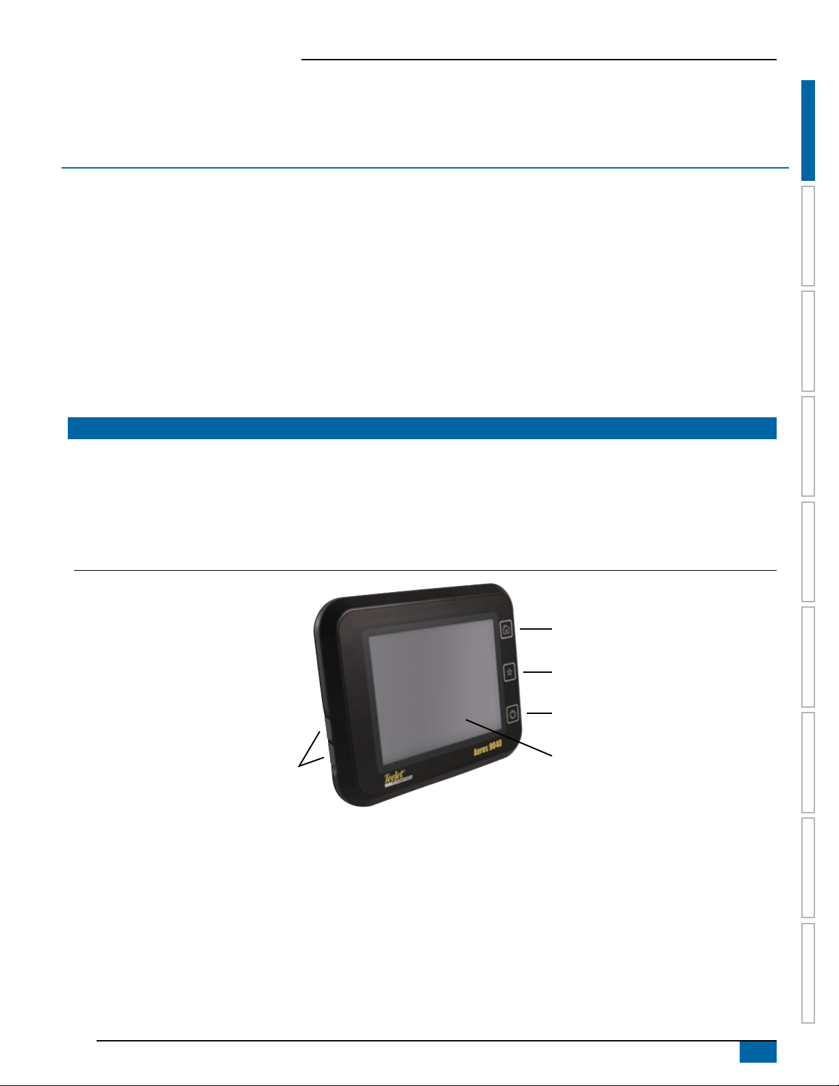
Figure 1-1: Aeros 9040 console front
Home button
Favorites button
USB ports with rubber covers
Power button
Bright touch screen
98-05304-EN R2
1
Aeros 9040 eld computer
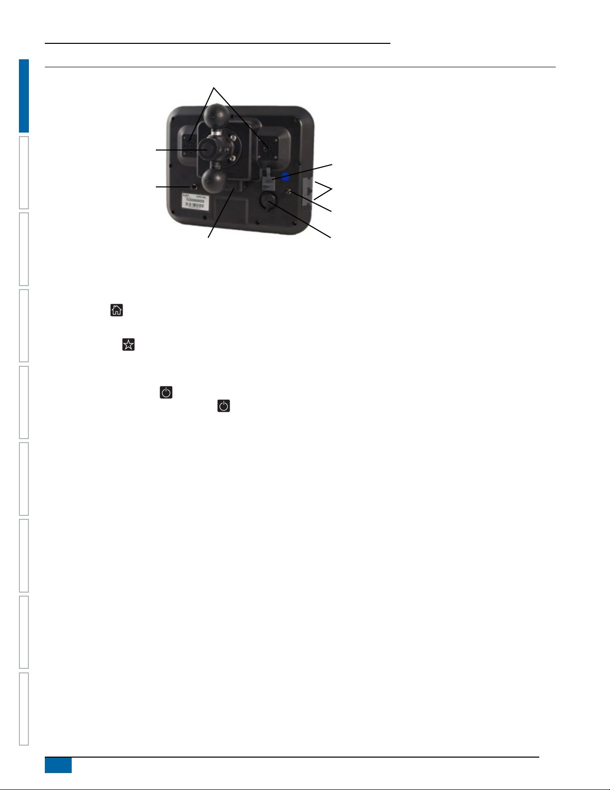
Figure 1-2: Aeros 9040 console back
Speakers
Integrated RAM mount
HOME SETUP GUIDANCEFULL SCREEN IMPLEMENTGNSS RATE CONTROL APPENDIXINTRODUCTION
(assembly required)
Speed digital (LAN) connection
with rubber cover
WiFi antenna connection
Power connection
USB ports with rubber covers
GNSS antenna connection
Camera connection
with rubber cover
Buttons
Home
The Home button provides a shortcut to the Home screen.
Favorites
The Favorites button provides a shortcut to a frequently used console bottom tab. To assign a tab to the button, navigate to that tab’s
screen, then press and hold the Favorites button until it beeps.
Power on/off
On – Press the POWER button to power on the console. Upon power up, the Aeros will begin its start up sequence.
Off – Press and briey hold the POWER button until a conrmation screen acknowledges shut down mode.
WARNING! Wait 10 seconds before restarting the console.
RealView® camera
The TeeJet Technologies RealView camera allows video images to be displayed on the Aeros screen. The camera can be pointed forward to
enable RealView guidance over video, or it can be positioned to view other operational aspects of your equipment. The camera is equipped
with a exible RAM mount, integral sun shade and provides infrared illumination, allowing clear video images even in dark conditions.
Additional information
All changes are saved automatically.
The console needs to be cycled off and back on when changing or attaching equipment to the Aeros system.
Start up sequence
The console takes approximately two-three minutes to power up. During this time a series of screens will be displayed, LEDs will power on
and off, and brightness levels will uctuate. Once the power up sequence has completed, the Home screen will appear.
Recommended antenna installation
The GNSS antenna should be mounted as far forward as possible on top of the cab on a metal surface of at least 10 cm × 10 cm.
USB ports
Only one USB port can be used at any given time.
2
www.teejet.com
Aeros 9040 eld computer
BASIC SCREEN USE
The Aeros 9040 can be used as a simple current job system or advanced multi-job system. Regardless of which mode the console is in, the
basic screen functions are the same.
• Bottom tabs and side tabs access the various screens and sub-screens
• Warnings and information pop-ups inform user of console activities and details on setup or guidance functions
• Setup options can easily be set using the drop-down menus or keyboard entry screens
To quickly nd a setup feature, see “Aeros console menu settings” in this manual.
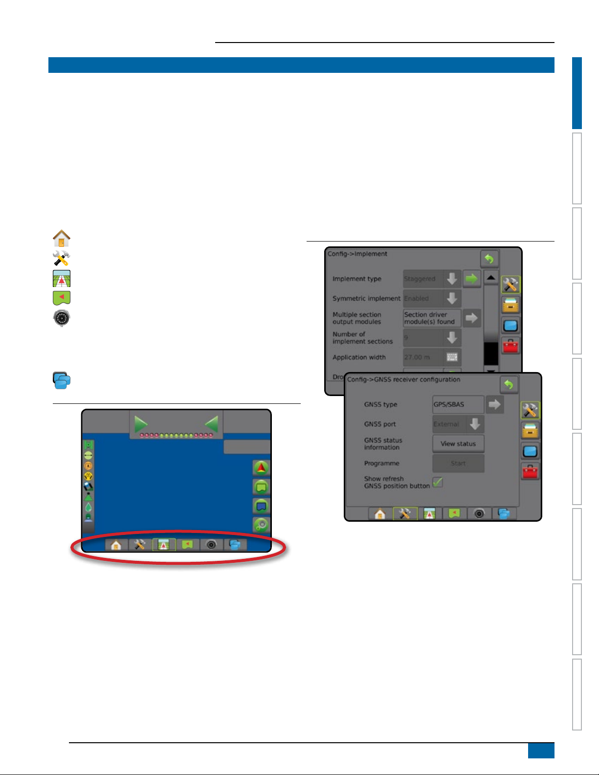
Bottom tab keys
The bottom tab keys are always available on screen. These keys
give access to jobs, setup options, and navigation.
Home/job screen
System setup
Vehicle view guidance
Field view guidance
RealView guidance or
RealView camera full screen video view
NOTE: RealView Guidance options are only available with a
camera installed on the system.
ISOBUS universal terminal
Figure 1-3: Bottom tab keys
0.00
ha
0.0
0.0
km/h
3.5
(bar)
Unavailable options when job is active
When a job is active some setup options are unavailable: see “Aeros
console menu settings” in this manual.
Figure 1-4: Examples of unavailable options
HOMESETUPGUIDANCE FULL SCREENIMPLEMENT GNSSRATE CONTROLAPPENDIX INTRODUCTION
98-05304-EN R2
3
Aeros 9040 eld computer
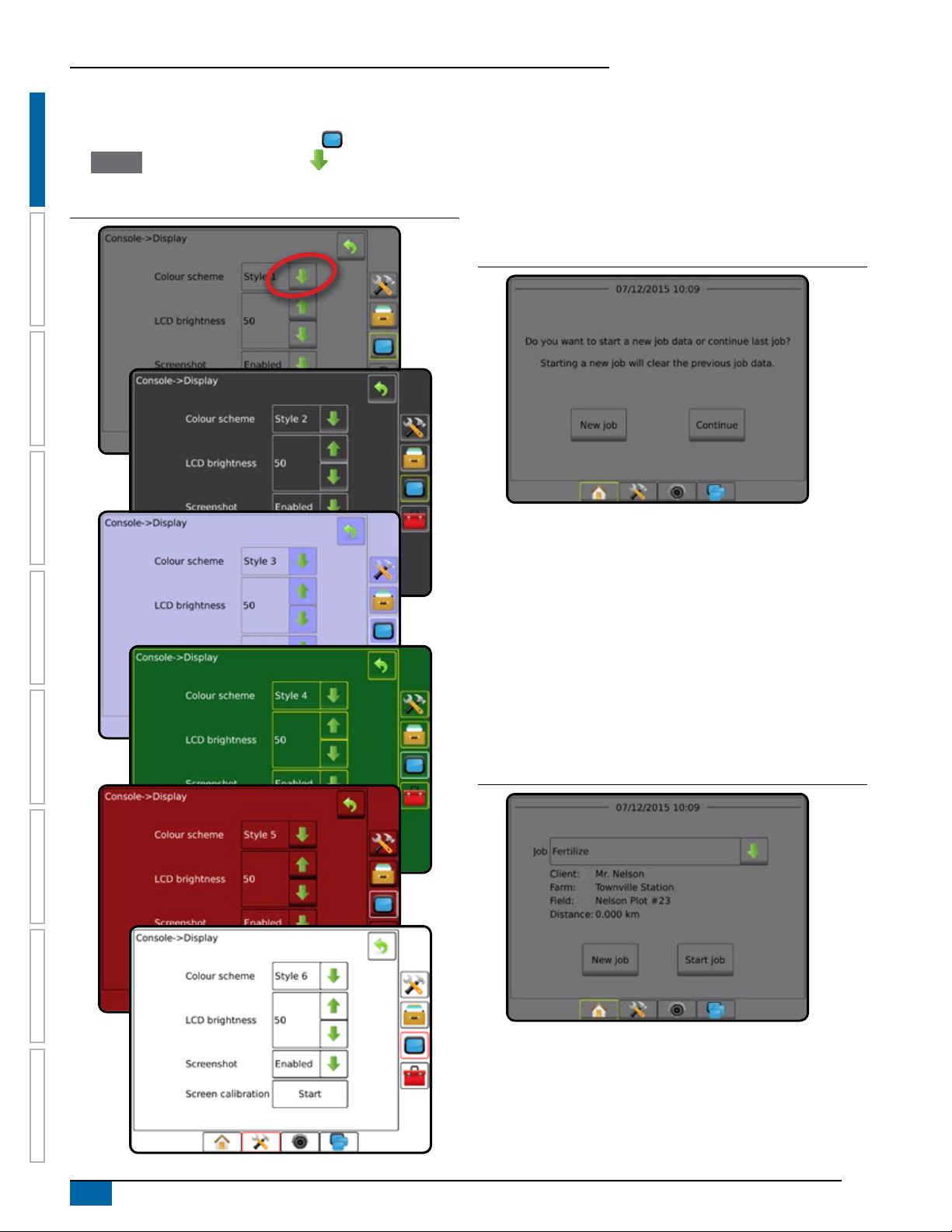
Console screen colours
The console is available in six colour schemes. From the System
setup bottom key, press CONSOLE side tab and enter
the Display options. Press DOWN arrow to access the Colour
scheme options to select colour mode.
Figure 1-5: Colour schemes
HOME SETUP GUIDANCEFULL SCREEN IMPLEMENTGNSS RATE CONTROL APPENDIXINTRODUCTION
Simple or advanced mode
To change between simple mode and advanced mode, see the
conguration chapter under Data –> Options.
In simple mode, only one job will be available at a time. Only
bounded area and coverage areas are displayed on the home
screen. Only the current job is available for saving in Reports. Use
with Fieldware Link is not available.
Figure 1-6: Simple mode home screen
In advanced mode, more than one job will be available at any time.
Client, farm, eld and job names; bounded and coverage areas;
application time; and distance from selected job are displayed on the
home screen. All saved job proles can be exported as a PDF, SHP
or KML le to a USB drive using Data -> Reports.
Client information, farm information, eld information, and
prescription maps can only be inputted using Fieldware Link. A job
name can only be edited using Fieldware Link.
A user can duplicate jobs for reuse of guidelines, boundaries, applied
data, prescription map and/or polygons using Fieldware Link or
Data -> Job data -> Manage in the console.
Figure 1-7: Advanced mode home screen
4
www.teejet.com
Aeros 9040 eld computer
Warnings and information pop-ups
A pop-up warning or information box will be displayed for
approximately ve (5) seconds. To remove the information box, tap
anywhere on the screen.
Figure 1-8: Example of information text box
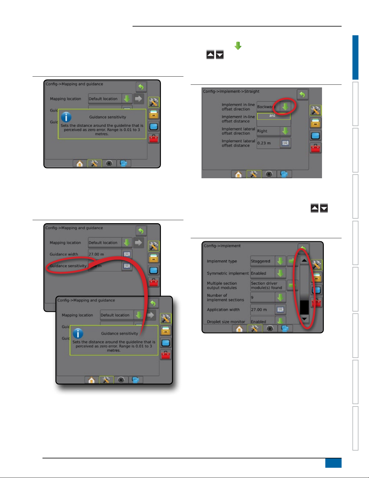
Setup option information
Press the option’s icon or option’s name of any menu item to display
a denition and range values of that item. To remove the information
box, press anywhere on the screen.
Figure 1-9: Example of information text box
Drop-down menu selections
Press DOWN arrow to access the options. Use the UP/DOWN
arrows or slide bar if necessary to scroll through the extended
list. Select the appropriate option. To close the list without selecting an
option, tap anywhere on the screen outside the drop-down menu.
Figure 1-10: Example of drop-down menu
HOMESETUPGUIDANCE FULL SCREENIMPLEMENT GNSSRATE CONTROLAPPENDIX INTRODUCTION
Backward
Forward
Scrolling screens
Some screens have more information or options that are visible
beyond the current screen. Use the UP/DOWN arrows or
slide bar to access additional options or information not currently
visible on the screen.
Figure 1-11: Example of scrolling screen
98-05304-EN R2
5
Aeros 9040 eld computer
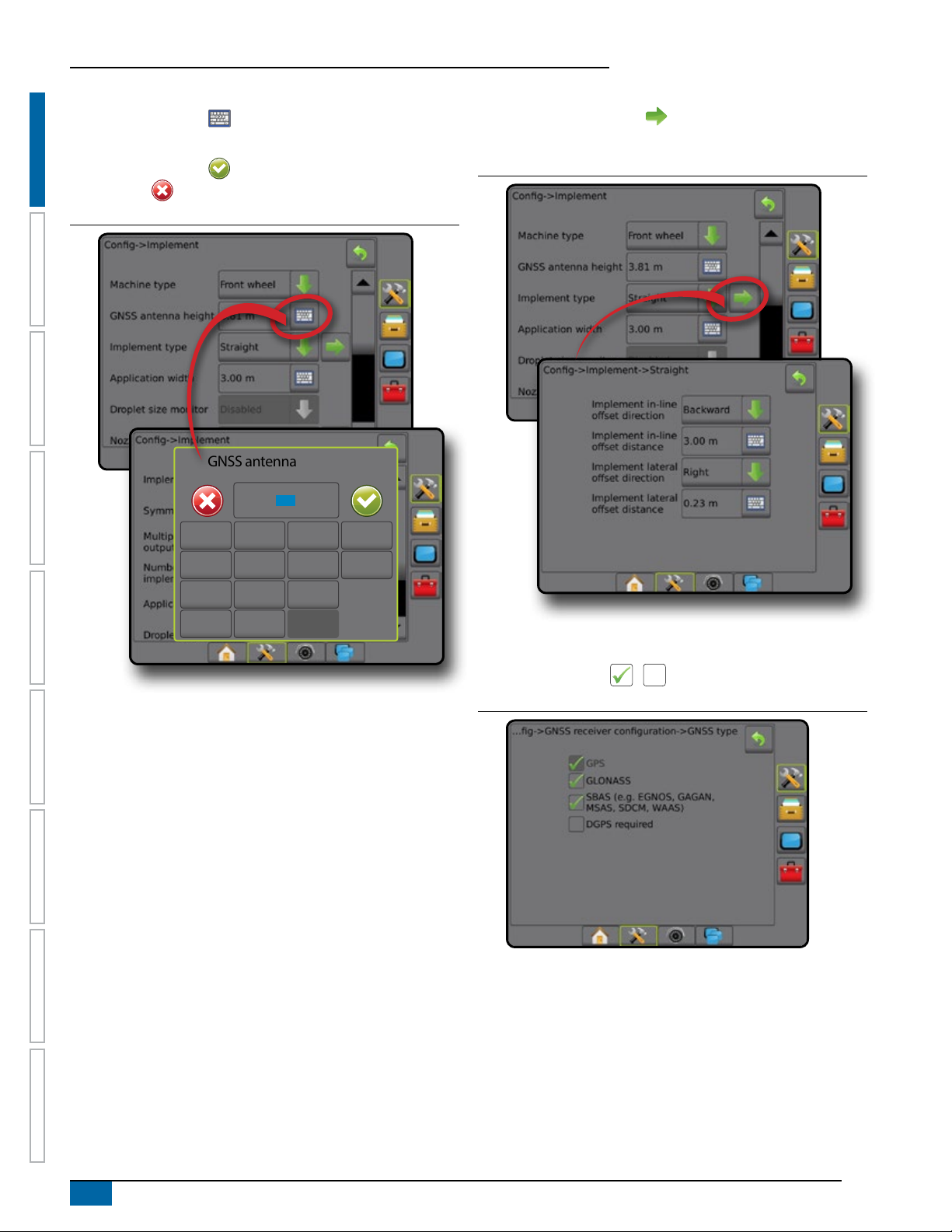
Keyboard entry screen
Press the KEYPAD icon . Use the numeric keypad to enter
a value.
Press the ACCEPT icon to save the settings or the
CANCEL icon to leave the keypad without saving.
Figure 1-12: Example of keyboard
HOME SETUP GUIDANCEFULL SCREEN IMPLEMENTGNSS RATE CONTROL APPENDIXINTRODUCTION
GNSS antenna height (m)
3.50
1 2 3
Next page
Press the NEXT PAGE arrow to set up additional options for the
selected item.
Figure 1-13: Example of next page
Clear
4 5 6 <--
7 8 9
0 . +/-
Checkboxes
Press the CHECKBOX / to select or deselect.
Figure 1-14: Example of checkboxes
6
www.teejet.com
Aeros 9040 eld computer
CHAPTER 2 JOBS / HOME SCREEN
Once the power up sequence has completed and the console is receiving GNSS, the Home screen will appear with the option to start a new
job or continue an existing job.
Setup for the specic machine and its components must be completed before starting a job. Once a job is
active, some setup options can no longer be changed. See “Aeros console menu settings” in the appendix of this manual.
To change between simple and advanced mode, go to Data-> Options-> Job mode in the System setup.
Simple mode
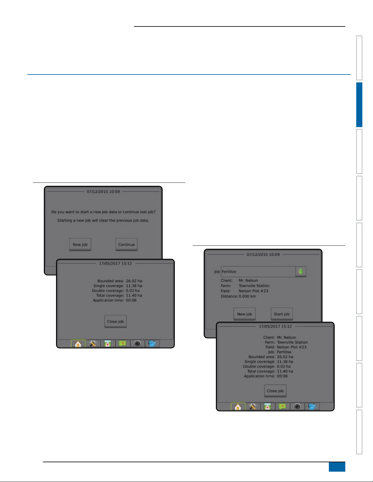
In simple mode, only one job will be available at a time. Only
bounded area, coverage areas, and application time are displayed
on the home screen. Only the current job is available for saving in
Reports. Use with Fieldware Link is not available.
Figure 2-1: Simple mode home screen
Advanced mode
In advanced mode, more than one job will be available at any time.
Client, farm, eld and job names; bounded and coverage areas;
application time; and distance from selected job are displayed on the
home screen. All saved job proles can be exported as a PDF, SHP
or KML le to a USB drive using Data -> Reports.
Client information, farm information, eld information, and
prescription maps can only be inputted using Fieldware Link. A job
name can only be edited using Fieldware Link.
A user can duplicate jobs for reuse of guidelines, boundaries, applied
data, prescription map and/or polygons using Fieldware Link or
Data -> Job data -> Manage in the console.
Figure 2-2: Advanced mode home screen
SETUPGUIDANCE FULL SCREENIMPLEMENT INTRODUCTIONGNSSRATE CONTROLAPPENDIX HOME
98-05304-EN R2
7
Aeros 9040 eld computer
SIMPLE MODE
Once the power up sequence has completed, the Home screen will
appear with the option to start a new job or continue an existing job.
The console must have GNSS before starting or continuing a job.
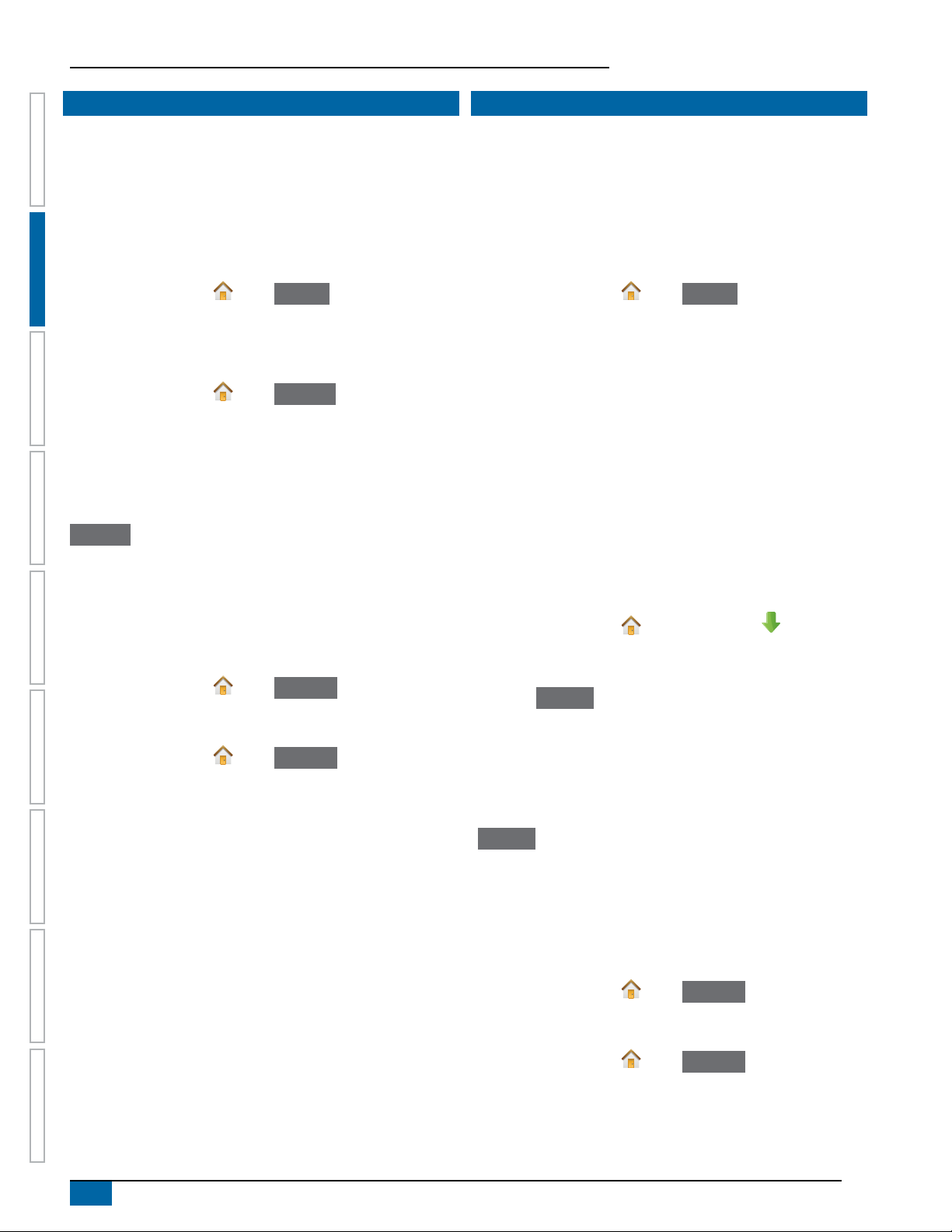
New job
Starting a new job will clear the previous job data.
To start a new job:
1. On the Home screen , press New job .
The console will jump to Vehicle View.
Continue job
To continue the existing job:
1. On the Home screen , press Continue .
The console will jump to Vehicle view and begin providing navigation
information.
Distance
SETUP GUIDANCEFULL SCREEN IMPLEMENTINTRODUCTION GNSS RATE CONTROL APPENDIXHOME
If a selected job is in a UTM zone other than the current or adjacent
UTM zone, “Out of range” will be displayed next to Distance, and
Continue will be disabled.
NOTE: For more information, see the UTM zone appendix.
If a selected job has no recorded information, Distance will show “No
data”.
Close job
To close a job:
1. On the Home screen , press Close job .
To create a report of the job when closing a job:
1. Insert a USB drive into the USB port of the console.
2. On the Home screen , press Close job .
3. Select:
►Yes – to create a report of the last job
►No – to return to the Home screen without saving
ADVANCED MODE
Once the power up sequence has completed, the Home screen will
appear with the option to start a new job or continue an existing job.
The console must have GNSS before starting or continuing a job.
New job
Starting a new job will clear the previous job data.
To start a new job:
1. On the Home screen , press New job .
2. Press:
►Yes – to automatically generate a name
►No – to enter a name using the on screen keyboard
Client, farm, and eld information are inputted using Fieldware Link.
The console will jump to Vehicle view.
Start job
The Aeros 9040 is programmed with a eld nder tool to assist the
user in nding the job closest to the vehicle’s location. With GNSS
acquired, the job pick list will be updated every ten seconds. During
this update, the list of jobs is sorted by distance and the closest two
jobs are displayed on the top of the list. The remaining jobs are listed
beneath these.
To continue the existing job:
1. On the Home screen , press DOWN arrow to access the
list of jobs saved in the console.
2. Select the job name to be started/continued.
3. Press Start job .
The console will jump to Vehicle View and begin providing navigation
information.
Distance
If a selected job is in a UTM zone other than the current or adjacent
UTM zone, “Out of range” will be displayed next to Distance, and
Start job will be disabled.
8
www.teejet.com
NOTE: For more information, see the UTM zone appendix.
If a selected job has no recorded information, Distance will show “No
data”.
Close job
To close a job:
1. On the Home screen , press Close job .
To create a report of the job when closing a job:
1. Insert a USB drive into the USB port of the console.
2. On the Home screen , press Close job .
3. Select:
►Yes – to create a report of the last job
►No – to return to the Home screen without saving
Aeros 9040 eld computer
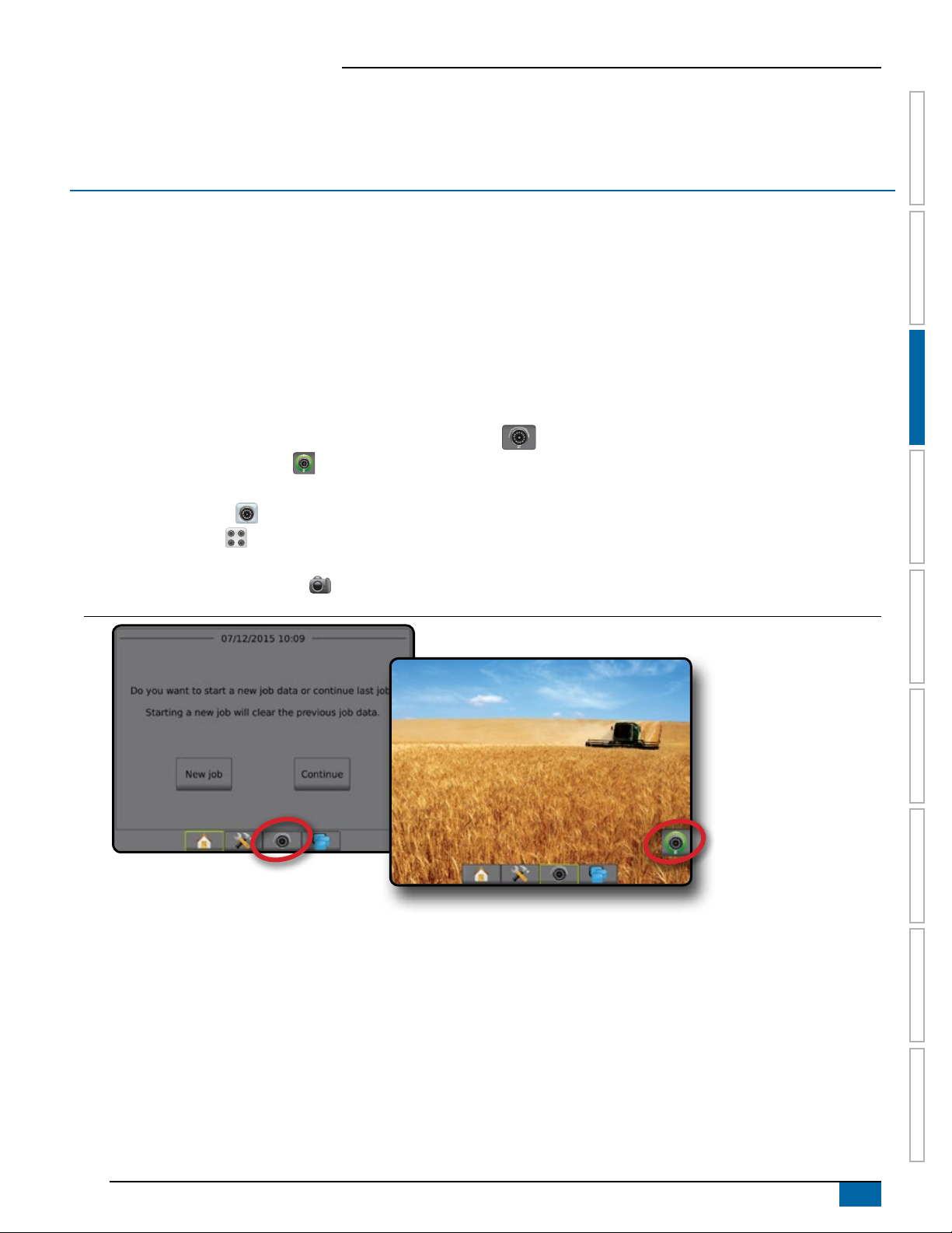
CHAPTER 3 FULL SCREEN VIDEO VIEW
RealView full screen video view allows live video input to be displayed. View video feed(s) and setup cameras without GNSS available.
Options for RealView guidance are not available on this screen.
►Single camera – a single camera is directly attached to the console
►Video selection module – if a Video Selection Module (VSM) is installed on the system, two (2) video options are available:
• One camera view – one of up to eight camera inputs can be selected to change the view of the video input.
• Split camera view – one of two sets of four camera inputs (A/B/C/D or E/F/G/H) can be selected to divide the screen into four
separate video feeds.
To adjust the camera view [reverse, upside down], go to Setup-> Conguration-> Video.
To enter Full screen video mode:
1. Press REALVIEW CAMERA FULL SCREEN VIDEO VIEW bottom tab .
2. Press REALVIEW OPTIONS tab to display RealView options.
3. Select from:
►Single camera view [VSM only] – one (1) of up to eight (8) camera inputs can be selected to change the view of the video input
►Split camera view [VSM only] – one (1) of two (2) sets of four (4) camera inputs (A/B/C/D or E/F/G/H) can be selected to divide the
screen into four separate video feeds
►RealView camera image capture – saves a still photo of the current view on the screen to a USB drive
Figure 3-1: RealView full screen video view
HOMESETUPGUIDANCE IMPLEMENT INTRODUCTIONGNSSRATE CONTROLAPPENDIX FULL SCREEN
98-05304-EN R2
9
Aeros 9040 eld computer
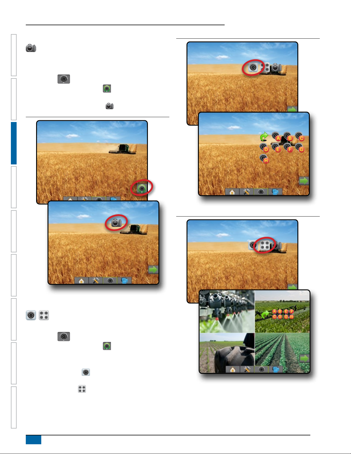
Camera snapshot
RealView camera snapshot saves a still photo of the current
view on the screen to a USB drive.
1. Insert USB drive.
2. Press REALVIEW CAMERA FULL SCREEN VIDEO VIEW
bottom tab .
3. Press REALVIEW OPTIONS tab to display RealView
HOME SETUP GUIDANCEIMPLEMENTINTRODUCTION GNSS RATE CONTROL APPENDIXFULL SCREEN
options.
4. Press CAMERA SNAPSHOT icon .
Figure 3-2: RealView camera full screen video view
Figure 3-3: Single camera selection with VSM
VSM camera options
If a Video selection module (VSM) is installed on the
system, two (2) video options are available:
1. Press REALVIEW CAMERA FULL SCREEN VIDEO VIEW
bottom tab .
2. Press REALVIEW OPTIONS tab to display RealView
options.
3. Select from:
►Single camera view – one (1) of up to eight (8) camera
inputs can be selected to change the view of the video input.
►Split camera view – one (1) of two (2) sets of four (4)
camera inputs (A/B/C/D or E/F/G/H) can be selected to divide
the screen into four separate video feeds.
Figure 3-4: Select split view with VSM
10
www.teejet.com
Aeros 9040 eld computer
CHAPTER 4 SYSTEM SETUP
System Setup is used to congure the console, the machine and its implements. Four side tabs access options for Machine/Implement
Conguration, Data management, Console settings, and Tools.
Overview
Four side tabs access setup options for:
Conguration
• Implement (straight, spreader, or staggered implement
congurations; nozzle selection information including droplet
size monitor, reverse conguration)
• Mapping and Guidance (mapping location, guidance sensitivity,
external lightbar)
• GNSS receiver conguration
• Video conguration
• Sensors (Input/output module (IOM) pressure sensor)
• Nozzle ow monitor
• ISOBUS conguration
• Product conguration
• AutoSteer
◄FieldPilot (valve setup, steering settings, valve test, valve
diagnostics, steering wheel sensor, steering angle sensor)
◄FieldPilot Pro / UniPilot Pro (manage vehicle, calibrations,
adjustments, select qi values, transport mode, service mode)
• Tilt correction
HOMEGUIDANCE FULL SCREENIMPLEMENT INTRODUCTIONGNSSRATE CONTROLAPPENDIX SETUP
Data management
• Job data (transfer, manage)
• Reports
• Options (job mode)
• Machine settings (transfer, manage)
Console settings
• About (system information)
• Display
• Cultural
• Audio volume
• Demo GNSS
• Feature unlock
Tools
• Upload software
• Extras (calculator, units converter)
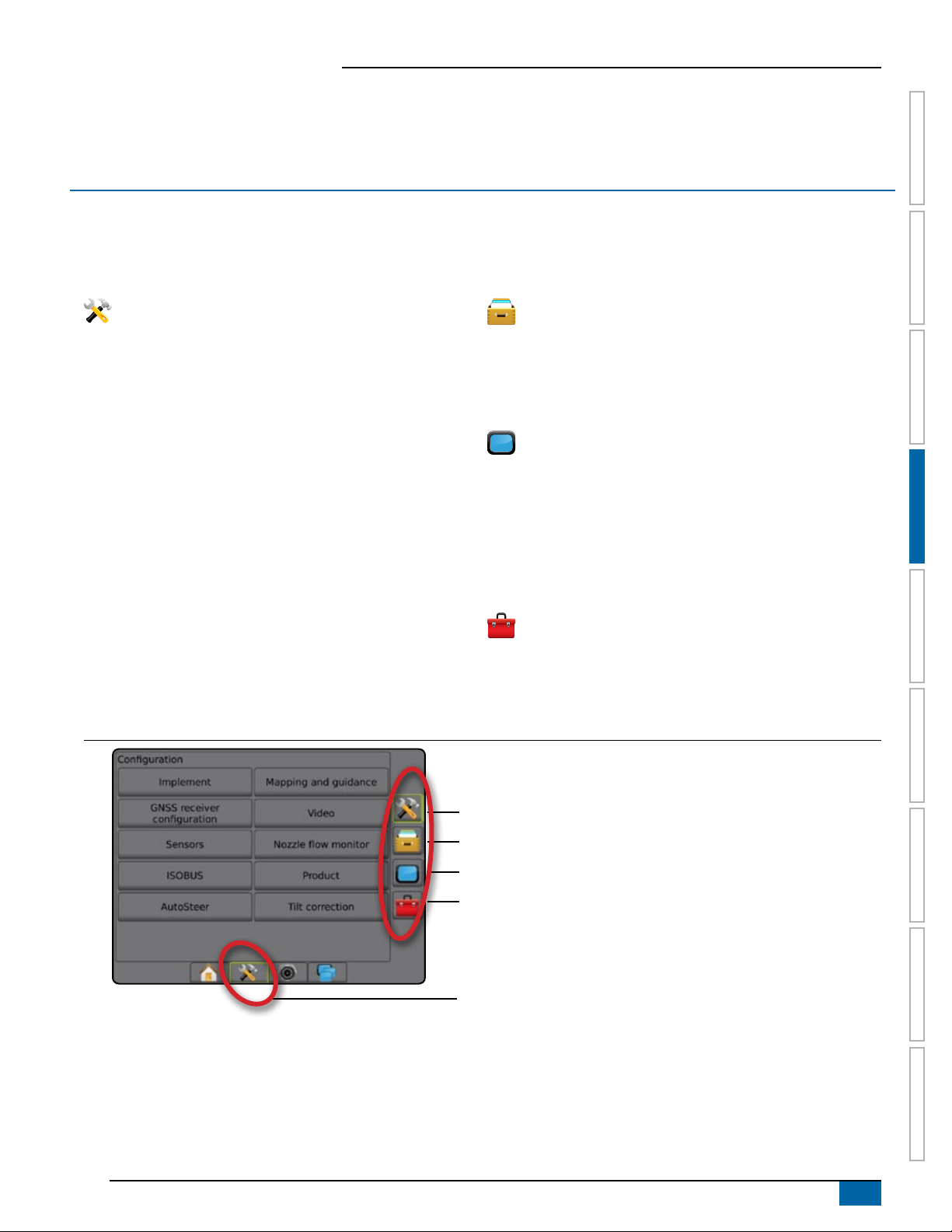
Figure 4-1: Setup options
Side tabs
Conguration side tab
Data management side tab
Console settings side tab
Tools side tab
System setup bottom tab
98-05304-EN R2
11
Aeros 9040 eld computer
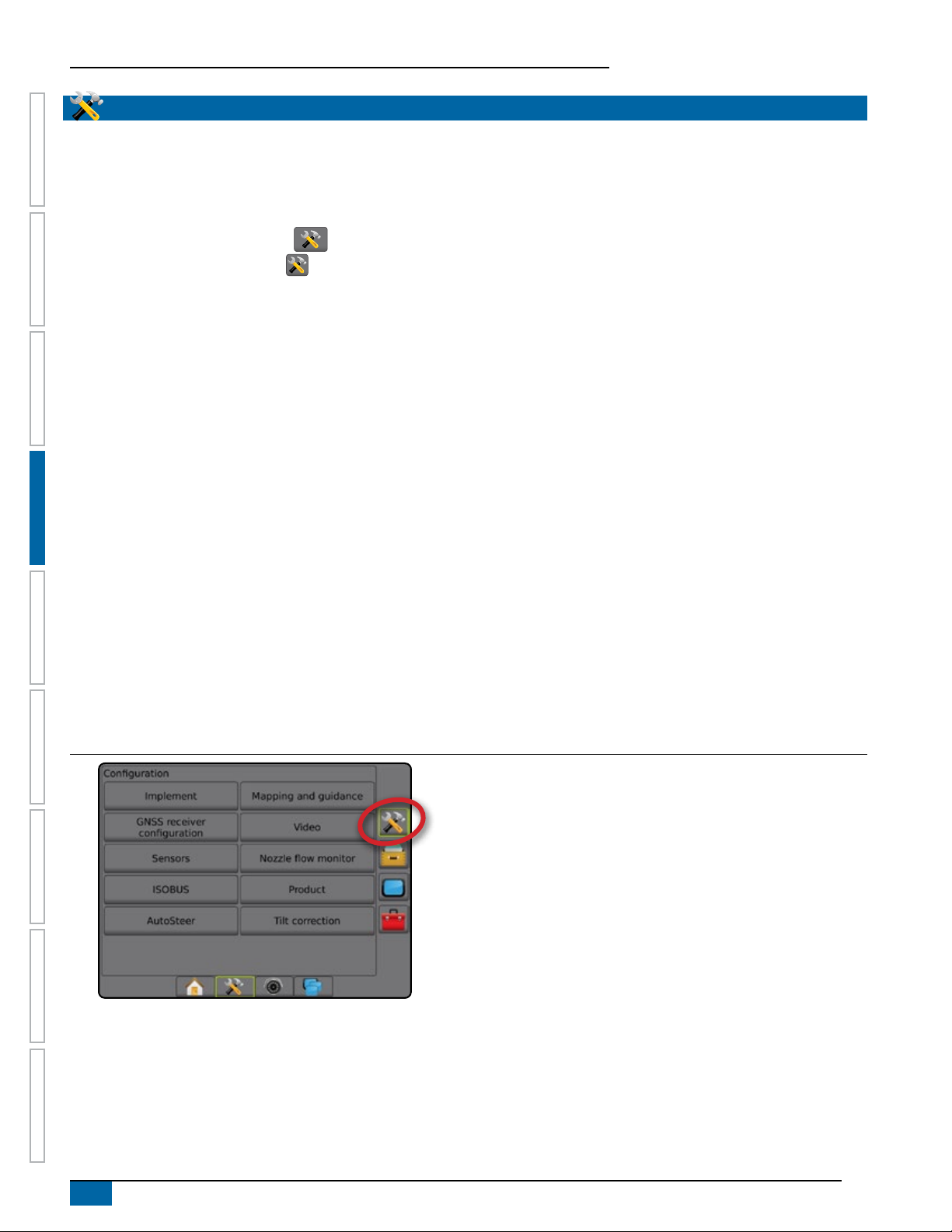
CONFIGURATION
Conguration is used to congure the system components including
implements, guides, steering, monitors and sensors.
NOTE: Feature availability will vary depending on the devices
available and unlocked on the Aeros 9040 system.
1. Press SYSTEM SETUP bottom tab .
HOME GUIDANCEFULL SCREEN IMPLEMENTINTRODUC TION GNSS RATE CONTROL APPENDIXSETUP
2. Press CONFIGURATION side tab .
3. Select from:
►Implement – used to set (as appropriate) machine type,
GNSS antenna height, implement type, symmetric implement
layout, section output modules, number of implement
sections, application/working width, droplet size monitor,
nozzle selection, nozzle spacing, BoomPilot start mode,
reverse sense module
● In Straight mode – in-line/lateral implement offset direction/
distance, overlap percentage, implement delay on/off time
● In Spreader mode:
TeeJet – antenna to disks distance, lateral implement offset
direction/distance, overlap percentage, delay on/off times,
spread offset distance, section offset distances, section
lengths
OEM – antenna to disks distance, lateral implement offset
direction/distance, start/stop distance, section start/stop
offset distances
● In Staggered mode – in-line/lateral section 1 offset
direction/distance, overlap percentage, delay on/off times,
section offsets
Figure 4-2: Configuration options
►Mapping and guidance – used to congure the mapping
location, guidance width, guidance sensitivity (cross track
error) and/or an optional external lightbar module (ELM)
►GNSS – used to establish GNSS type, port, and PRN, as well
as to view GNSS status information
►Video – used to set up individual cameras
►Sensors – used to establish pressure sensor settings
►Nozzle ow monitor – used to establish nozzle conguration,
and to establish and calibrate ow limits and alarm behavior
for nozzle ow monitors
►ISOBUS – used to select information for broadcast over the
ISOBUS, and in troubleshooting
►Product – used to congure product name, tank/bin volumes,
target application rates, increment for adjusting target rates,
and colour mapping maximum/minimum rate limits and
corresponding display colours
►AutoSteer – used to enable/disable and calibrate assisted/
auto steering
● FieldPilot – used to establish valve setup settings, steering
settings, steering wheel and steering angle sensor settings,
and to perform valve tests or valve diagnostics
● FieldPilot Pro / UniPilot Pro – used to manage vehicle
settings, calibrate sensors, select QI values, as well as
establish transport mode and service mode
►Tilt correction – used to enable/disable and calibrate the tilt
correction function, and improve application on hilly or sloped
terrain
12
www.teejet.com
Aeros 9040 eld computer
Implement
Implement setup is used to establish the various settings associated
with straight mode, spreader mode, or staggered mode. Available
settings will vary depending on the specic equipment present in the
system.
This section includes setup options for these implement
congurations:
►Single section
►Section(s) with ISOBUS sprayer/spreader setup
►Multiple sections with Section driver module or Switch function
module
NOTE: For more information, see the Implement chapter of this
manual.
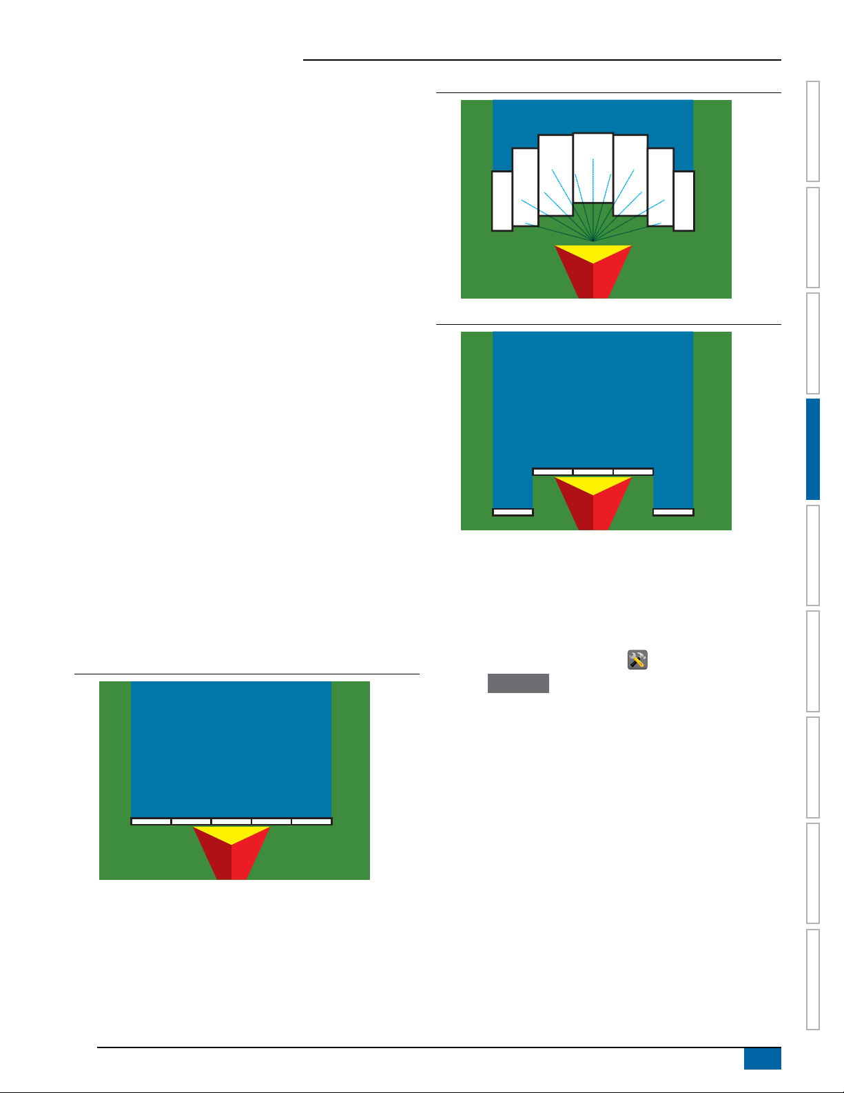
Implement type
Implement type selects the type of application pattern that most
closely represents your system.
● In Straight mode – the boom sections have no length and are
on a line a xed distance from the antenna
● In Spreader mode – a virtual line is created in line with the
delivery disks from which the application section or sections can
vary in length and can be at different distances from the line
(availability depends on the specic equipment in the system)
● In Staggered mode – a virtual line is created in line with
section 1 from which the application section or sections have
no length and can be at different distances from the line
(availability depends on the specic equipment in the system)
NOTE: For more information, see "Implement type" in the Implement
chapter of this manual.
Figure 4-3: Implement type – Straight
Figure 4-4: Implement type – Spreader
HOMEGUIDANCE FULL SCREENIMPLEMENT INTRODUCTIONGNSSRATE CONTROLAPPENDIX SETUP
Figure 4-5: Implement type – Staggered
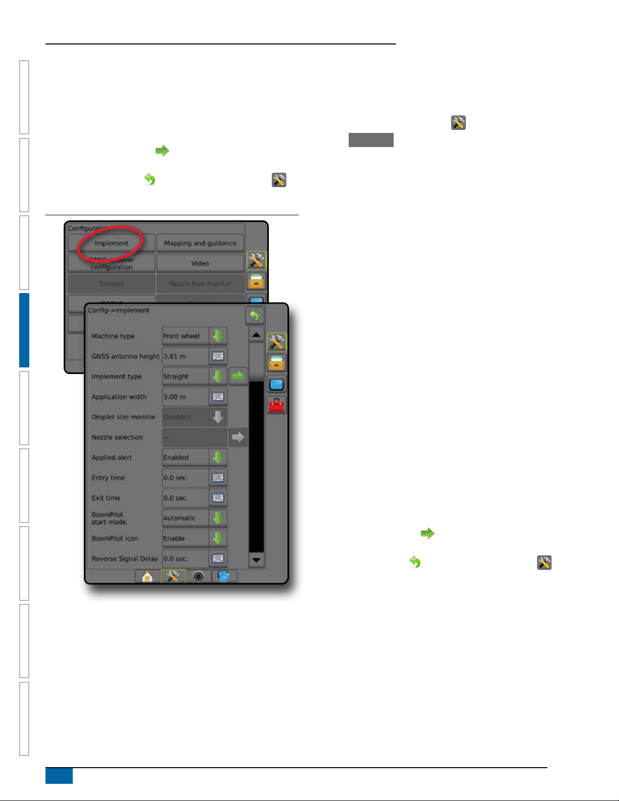
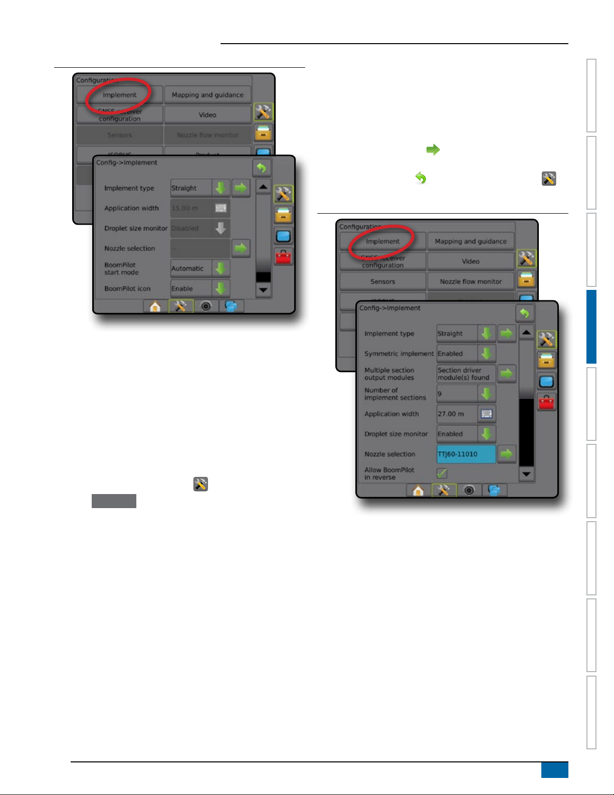
Single section setup
Single section setup is used when a SmartCable, Section driver
module (SDM), or Switch function module (SFM) is not on the
system (that is, no section control is present). The entire boom or
delivery area is considered to be one section.
1. Press CONFIGURATION side tab .
2. Press Implement .
3. Select from:
►Machine type [when available] – used to select the type of
machine that most closely represents your machine
►GNSS antenna height [when available] – used to measure the
height of the antenna from the ground
►Implement type – used to select the layout of the sections for
the applied product location
►Working width [Spreader implement type] – used to enter the
total width of the implement
►Application width [Straight implement type] – used to enter the
total width of the implement
►Droplet size monitor [when available] – used to enable droplet
size monitoring for up to ve preselected sprayer tips
►Nozzle selection [when available] – used to select the type of
sprayer nozzle (series and capacity) for determining droplet
size information
98-05304-EN R2
13
Aeros 9040 eld computer
►Applied alert – used to establish an alert to signal when
exiting or entering an applied area
►BoomPilot start mode – used to establish whether BoomPilot
will be controlled by speed or by the BoomPilot icon
►BoomPilot icon – used to activate the guidance screen icon
for manually controlling on-screen application painting
4. Press NEXT PAGE arrow to set up specic implement
HOME GUIDANCEFULL SCREEN IMPLEMENTINTRODUC TION GNSS RATE CONTROL APPENDIXSETUP
options. See the Implement chapter for details.
5. Press RETURN arrow or CONFIGURATION side tab to
return to the main Conguration screen.
Figure 4-6: Implement – Single section setup
Section(s) with ISOBUS sprayer/spreader setup
Some Implement options are completed on the ISOBUS ECU. When
these options are also available in the Implement setup section, they
will be greyed out or unavailable.
1. Press CONFIGURATION side tab .
2. Press
3. Select from:
4. Press NEXT PAGE arrow
5. Press RETURN arrow or CONFIGURATION side tab to
Implement .
►Machine type [when available] – used to select the type of
machine that most closely represents your machine
►GNSS antenna height [when available] – used to measure the
height of the antenna from the ground
►Implement type – used to select the layout of the sections for
the applied product location
►Application width [Straight implement type completed on
ISOBUS ECU] – used to display the total width of the
implement as entered on the ISOBUS sprayer
►Working width [Spreader implement type completed on
the ISOBUS ECU] – used to display the total width of the
implement as entered on the ISOBUS spreader
►Droplet size monitor [available only with Pressure sensor
interface kit] – used to enable droplet size monitoring for up to
ve sprayer tips
►Nozzle selection [Straight implement type completed on the
ISOBUS ECU] – used to display the type of sprayer nozzle as
entered on the ISOBUS sprayer
►Applied alert – [only available without a switchbox] used to
establish an alert to signal when exiting or entering an applied
area
►BoomPilot start mode – used to control BoomPilot
automatically by speed, or manually by BoomPilot icon
►BoomPilot icon – used to activate icon for manually controlling
BoomPilot
to set up specic implement
options. See the Implement chapter for details.
return to the main Conguration screen.
14
www.teejet.com
Aeros 9040 eld computer
Figure 4-7: Implement – with ISOBUS setup
►Working width [Spreader implement type] – used to enter the
total width of the implement
►Droplet size monitor [when available] – used to enable droplet
size monitoring for up to ve preselected sprayer tips
►Nozzle selection [Straight or Staggered implement type] –
used to select the type of sprayer nozzle
4. Press NEXT PAGE arrow to set up specic implement
options. See the Implement chapter for details.
5. Press RETURN arrow or CONFIGURATION side tab to
return to the main Conguration screen.
Figure 4-8: Implement – Multiple sections with SDM or SFM setup
HOMEGUIDANCE FULL SCREENIMPLEMENT INTRODUCTIONGNSSRATE CONTROLAPPENDIX SETUP
Multiple sections with SDM/SFM setup
Multiple sections with SDM/SFM setup is used when a Section driver
module (SDM) or switch function module (SFM) is on the system.
The boom or delivery area can include up to 15 sections of varying
width and (in spreader mode) length. Additional options available
with an SDM include application overlap, application delay, and
staggered mode.
The Switch function module enables manual and automated control
of up to 20 sections.
1. Press CONFIGURATION side tab .
2. Press
3. Select from:
Implement .
►Machine type [when available] – used to select the type of
machine that most closely represents your machine
►GNSS antenna height [when available] – used to measure the
height of the antenna from the ground
►Implement type – used to select the layout of the sections for
the applied product location
►Symmetric implement – used to establish if sections are
paired and therefore share the same width, offset, and length
values
►Multiple section output modules – used to enable use of
multiple section output modules on the CAN bus
►Number of implement sections – used to select the number of
implement sections
►Application width [Straight or Staggered implement type] –
used to enter the total width of all sections of the implement
98-05304-EN R2
15
Aeros 9040 eld computer
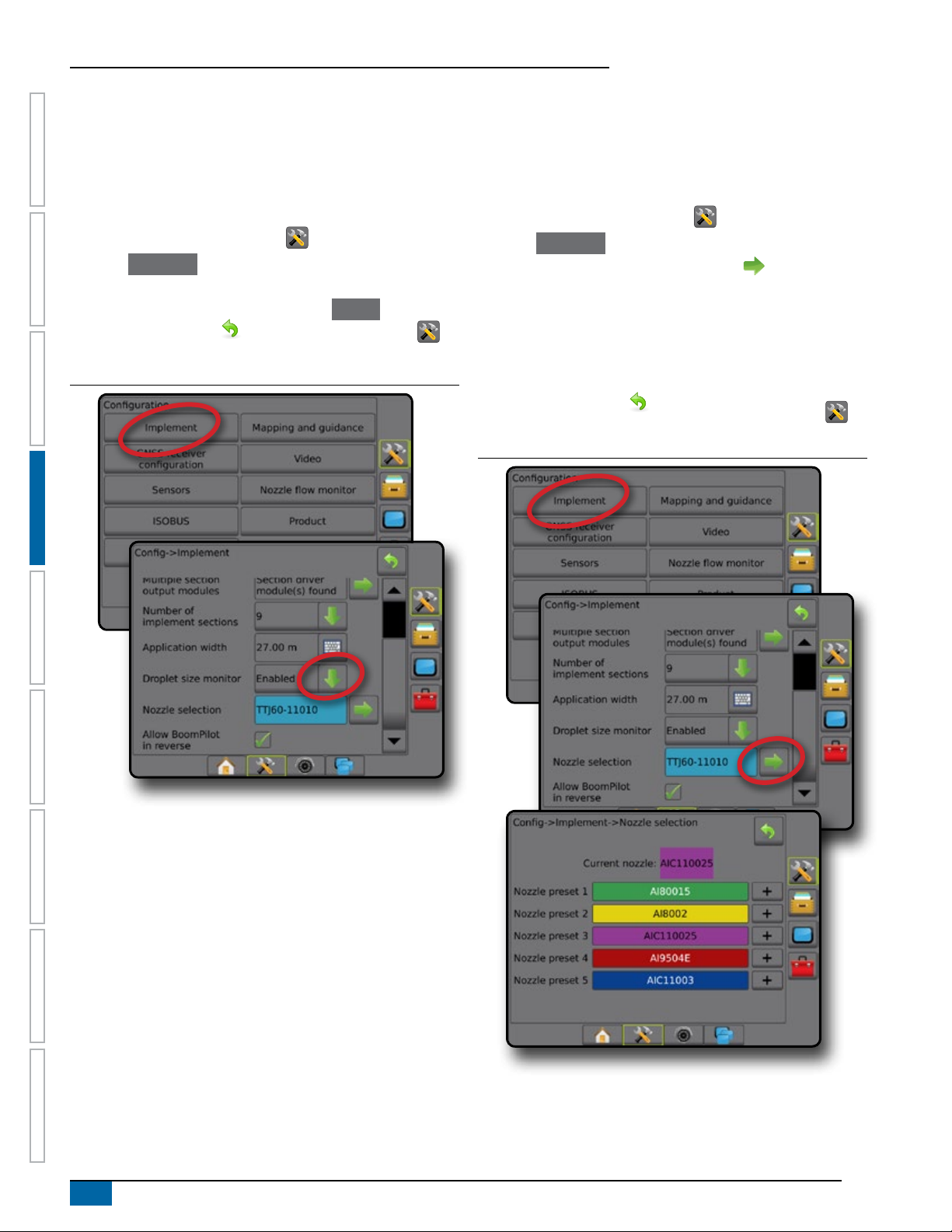
Droplet size monitor
When the system includes a Pressure sensor interface kit (PSIK),
Droplet size monitor can be enabled/disabled. The DSM then
becomes available on the operation screens.
NOTE: For more information, see "Droplet size monitor" in the
Implement chapter of this manual.
1. Press CONFIGURATION side tab .
HOME GUIDANCEFULL SCREEN IMPLEMENTINTRODUC TION GNSS RATE CONTROL APPENDIXSETUP
2. Press
3. Select if Droplet size monitor is enabled or disabled. (If enabling,
4. Press RETURN arrow or CONFIGURATION side tab to
Figure 4-9: Droplet size monitor
Implement .
also read displayed information and press
return to the main Conguration screen.
Accept .)
Nozzle selection
Nozzle selection enables up to ve (5) tips to be preset for quick
recall, and the current nozzle to be selected.
NOTE: For more information, see "Nozzle selection" in the
Implement chapter of this manual.
1. Press CONFIGURATION side tab .
2. Press
3. Press Nozzle selection NEXT PAGE arrow
4. Select from:
5. Press RETURN arrow
Figure 4-10: Nozzle selection
Implement .
.
►Nozzle preset 1-5 – selects up to ve (5) tips for quick recall,
and selected the current nozzle for determining droplet size
information
►Current nozzle – displays the current nozzle
or CONFIGURATION side tab to
return to the main Conguration screen.
16
www.teejet.com
Aeros 9040 eld computer
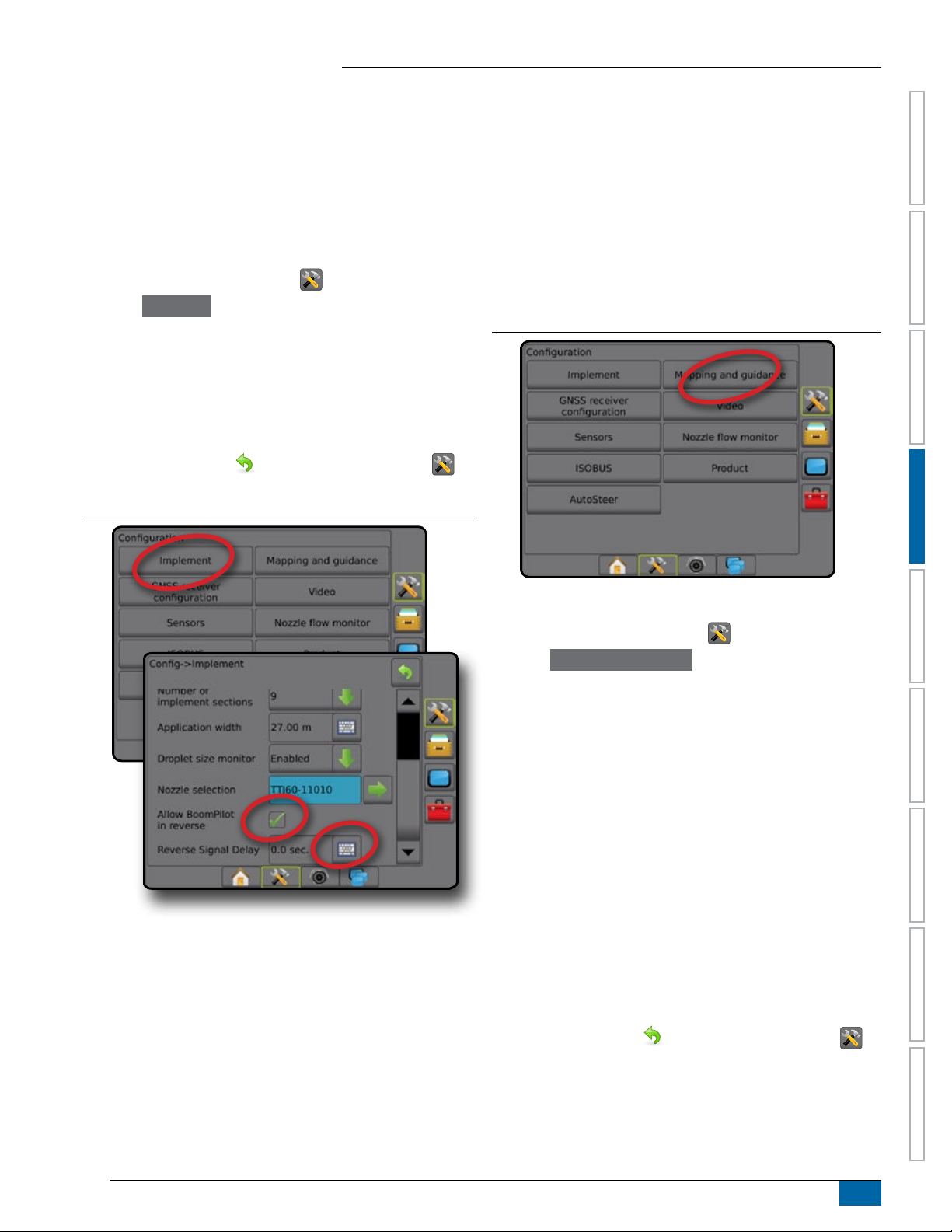
Reverse sense options
Reverse sense options are used when adding a Reverse sense
module or SCM Pro (Steering control module Pro for FieldPilot
Pro/UniPilot Pro) to any conguration.. This allows for application
mapping and control, and on-screen guidance when traveling in
reverse.
NOTE: For more information, see "Reverse sense" in the Implement
chapter of this manual.
1. Press CONFIGURATION side tab .
2. Press
3. Select:
4. Press RETURN arrow
Figure 4-11: Reverse sense
Implement .
►Allow BoomPilot in reverse [when available] – used to enable
BoomPilot function while traveling in reverse
►Reverse signal delay – used to set the delay when going
from forward to reverse or reverse to forward, after which the
vehicle icon on a navigation screen changes direction
or CONFIGURATION side tab to
return to the main Conguration screen.
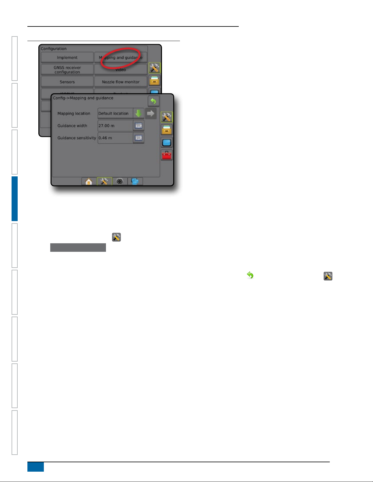
Mapping and guidance
Mapping and guidance options are used to congure the mapping
location, guidance width, guidance sensitivity (cross track error) and/
or an optional external lightbar module (ELM).
● Mapping and guidance [console only] – used to congure the
mapping location, guidance width and guidance sensitivity/
cross track error shown on the on screen guidance bar
● Mapping and guidance [using an external lightbar] – used to
congure an optional external lightbar module (ELM) which
provides additional guidance information.
Figure 4-12: Mapping and guidance
HOMEGUIDANCE FULL SCREENIMPLEMENT INTRODUCTIONGNSSRATE CONTROLAPPENDIX SETUP
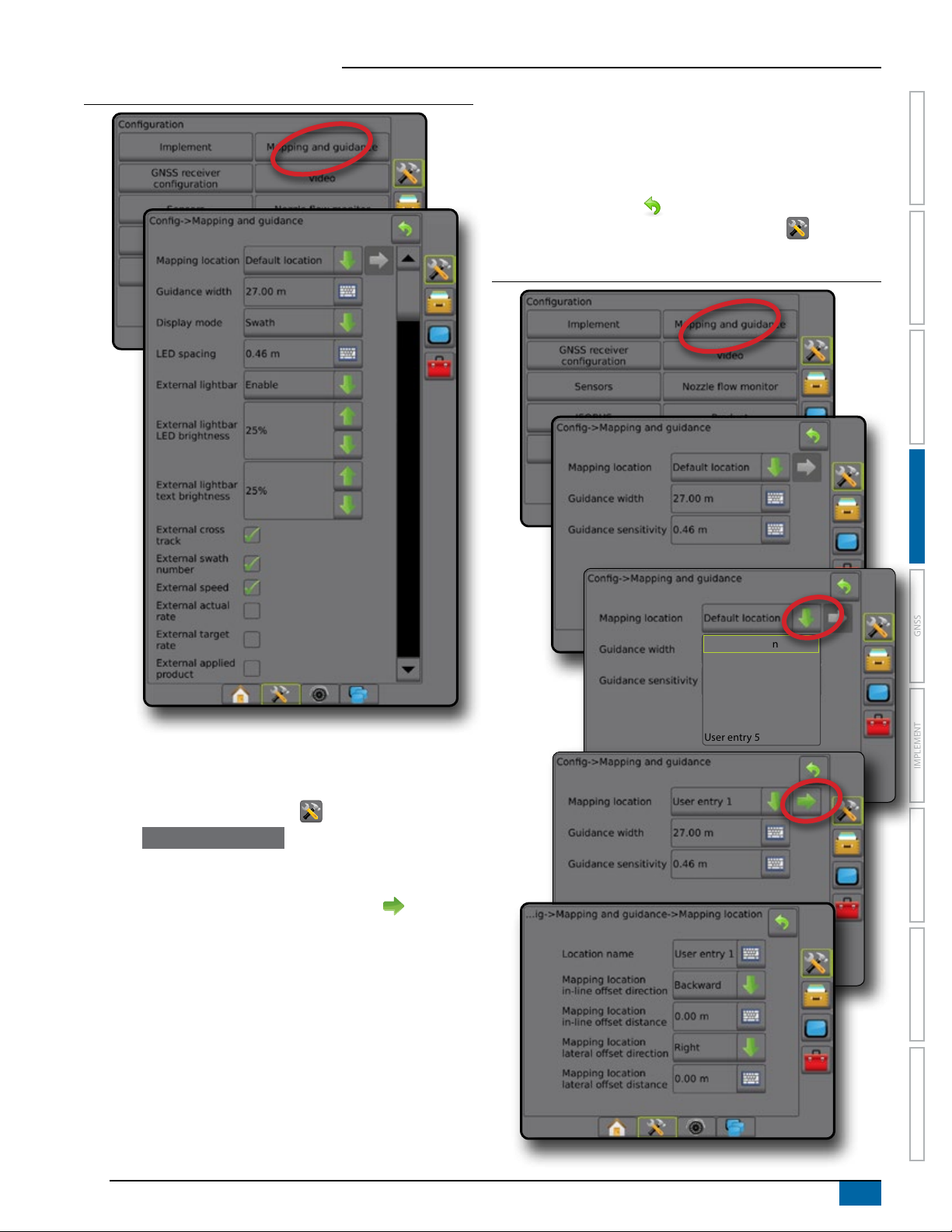
Mapping and guidance [console only]
1. Press CONFIGURATION side tab .
2. Press Mapping and guidance .
3. Select:
►Mapping location – establishes the location from which the
boundary or polygon will be mapped.
● Default location – While creating an exterior boundary or
polygon, the line will be to the exterior of the outermost
active section. While creating an interior boundary, the line
will be to the interior of the innermost active section. If no
sections are active, the boundary will be marked to the end
of the outermost section.
● User entry – in-line and lateral offset from the GNSS
antenna directions and distances can be specied by the
user. Up to ve (5) user entries can be created. See "User
entered mapping location" for details.
►Guidance width – used to set the distance between guidelines
►Guidance sensitivity – sets the distance around the guideline
that is perceived as zero error.
4. Press RETURN arrow
return to the main Conguration screen.
or CONFIGURATION side tab to
98-05304-EN R2
17
Aeros 9040 eld computer
Figure 4-13: Mapping and guidance
HOME GUIDANCEFULL SCREEN IMPLEMENTINTRODUC TION GNSS RATE CONTROL APPENDIXSETUP
Mapping and guidance using an external lightbar
Additional conguration options are available when using an external
lightbar.
1. Press CONFIGURATION side tab .
2. Press Mapping and guidance .
3. Select from:
►Mapping location – establishes the location from which the
boundary or polygon will be mapped.
● Default location – While creating an exterior boundary or
polygon, the line will be to the exterior of the outermost
active section. While creating an interior boundary, the line
will be to the interior of the innermost active section. If no
sections are active, the boundary will be marked to the end
of the outermost section.
● User entry – in-line and lateral offset from the GNSS
antenna directions and distances can be specied by the
user. Up to ve (5) user entries can be created. See "User
Entered Mapping Location" for details.
►Guidance width – used to set the distance between guidelines
►Display mode – when External lightbar is "enabled",
determines whether the lightbar represents the swath or
vehicle
● When set to "swath", the LEDs represent guideline location
and the moving LED represents the vehicle
● When set to "vehicle", the center LED represents vehicle
location and the moving LED represents the guideline
►LED spacing –
● When External lightbar is "enabled", sets the distance
away from the guideline or vehicle each illuminated LED
represents
● When External lightbar is "disabled", sets the distance
around the guideline that is perceived as zero error
►External lightbar – enable/disable use of the external lightbar
4. With the External lightbar module (ELM) enabled, select from:
►External lightbar LED Brightness – adjusts the brightness of
the external lightbar LEDs
►External lightbar text brightness – adjusts the brightness of
the external lightbar text
►External cross track – enable/disable display of cross track
error information on the external lightbar
►External swath number – enable/disable display of swath
number information on the external lightbar
►External speed – enable/disable display of speed information
on the external lightbar
►External actual rate [available with rate control] – enable/
disable display of actual rate information on the external
lightbar
►External target rate [available with rate control] – enable/
disable display of target rate information on the external
lightbar.
►External applied product [available with rate control] – enable/
disable display of applied product information on the external
lightbar
5. Press RETURN arrow or CONFIGURATION side tab to
return to the main Conguration screen.
18
www.teejet.com
Aeros 9040 eld computer
Figure 4-14: Mapping and guidance with external lightbar
the mapping location while facing in the machine’s forward
direction
►Mapping location lateral offset distance – used to dene the
lateral distance from the centreline of the machine to the
mapping location
6. Press RETURN arrow to return to the Mapping and
Guidance screen or CONFIGURATION side tab to return to
the main Conguration screen.
Figure 4-15: User entered mapping location
HOMEGUIDANCE FULL SCREENIMPLEMENT INTRODUCTIONGNSSRATE CONTROLAPPENDIX SETUP
User entered mapping location
Mapping location establishes the location from which boundary and
polygon mapping will take place.
1. Press CONFIGURATION side tab .
2. Press Mapping and guidance .
3. Select user entry location from the Mapping Locations dropdown options.
4. Press MAPPING LOCATION NEXT PAGE arrow
the selected specic mapping location options.
5. Select:
►Location name – used to enter the name of the mapping
location for the current user entry selected
►Mapping location in-line offset direction – used to select
whether the mapping location is located in front of or behind
the GNSS antenna as the vehicle moves in a forward direction
►Mapping location in-line offset distance – used to dene the in-
line distance from the GNSS antenna to the mapping location
►Mapping location lateral offset direction – used to select
the lateral direction from the centreline of the machine to
to set up
Default location
User entry 1
User entry 2
User entry 3
User entry 4
User entry 5
98-05304-EN R2
19
Aeros 9040 eld computer
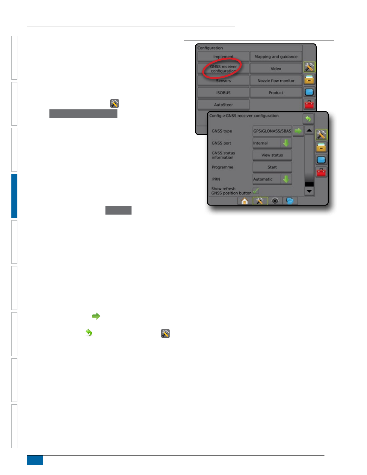
GNSS
GNSS is used to congure GNSS type, GNSS port, and PRN, as
well as to view GNSS status information.
NOTE: For more information, see the GNSS chapter of this manual.
These settings are required for assisted/auto steering, tilt
sensor operation, and rate control functionality, as well as
HOME GUIDANCEFULL SCREEN IMPLEMENTINTRODUC TION GNSS RATE CONTROL APPENDIXSETUP
proper implement operation.
1. Press CONFIGURATION side tab .
2. Press GNSS receiver conguration .
3. Select from:
►GNSS type – sets to accept GNSS source transmissions:
GPS, GLONASS, SBAS (with or without DGPS required)
►GNSS port – sets GNSS communication port to either internal
or external
►GNSS status information – displays current GNSS status
information
►Program – only TeeJet support technicians should use this
feature
►PRN – selects the rst of two possible SBAS PRN's to provide
SBAS correction data. Set to Automatic for automatic PRN
selection.
►Alternate PRN – when PRN is not automatic, allows possible
selection of a second SBAS PRN to provide correction data
►Show refresh GNSS position button – establishes if the
refresh GNSS position button is available on the guidance
screens.
NOTE: Activating the refresh while in a job will cause a
momentary interruption in the relay of GNSS data. This
will most likely result in sections already on in automatic
BoomPilot mode to go off for a short period of time.
Figure 4-16: GNSS options
PRN not shown
PRN options are only available with SBAS GNSS type selected.
The refresh should not be done during active application.
4. Press NEXT PAGE arrow to set up the selected specic
GNSS options.
5. Press RETURN arrow or CONFIGURATION side tab to
return to the main Conguration screen.
20
www.teejet.com
Aeros 9040 eld computer
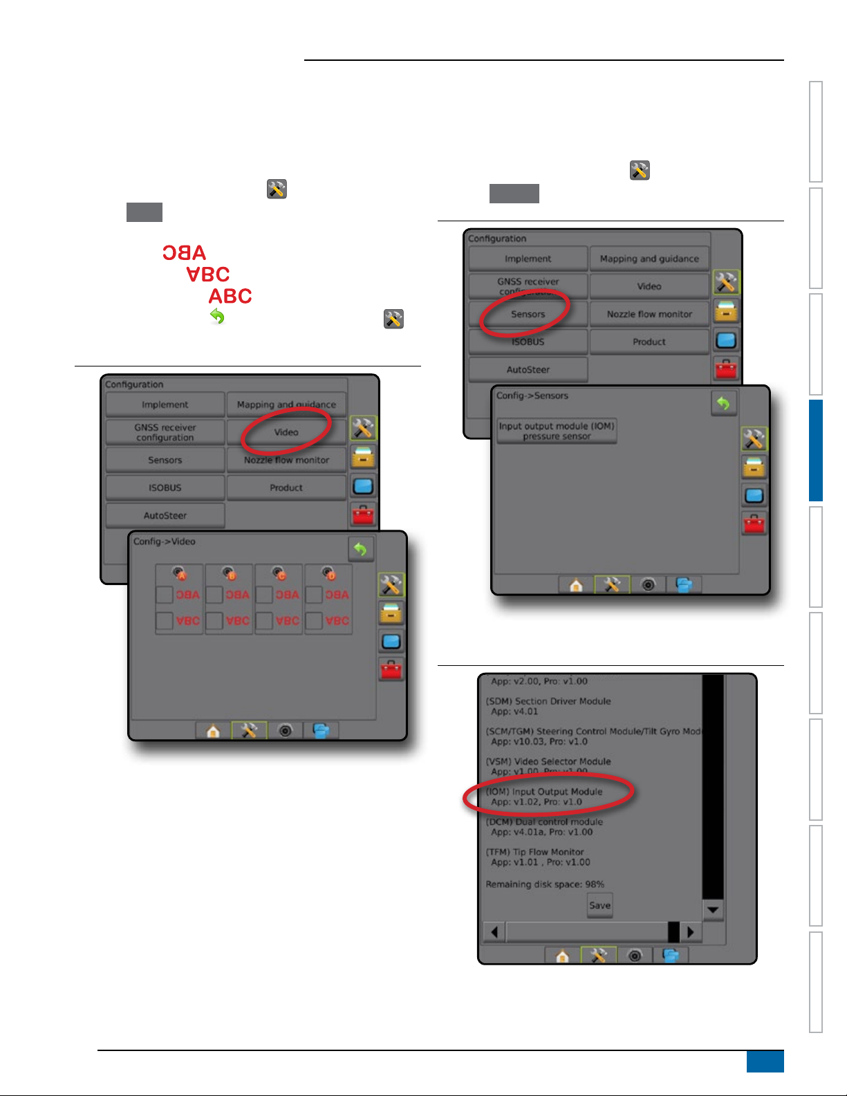
Video
Video setup is used to set up a single directly connected camera
or individual cameras while using an eight (8) channel or four (4)
channel Video selector module (VSM). Up to 8 cameras can be
congured if a VSM is installed.
1. Press CONFIGURATION side tab .
2. Press Video .
3. Select the appropriate check box(es):
►Reverse –
►Upside down –
For normal video view un-check all check boxes.
4. Press RETURN arrow or CONFIGURATION side tab to
return to the main Conguration screen.
Figure 4-17: Video with 4 channel VSM options
Sensors
When a Pressure sensor interface kit (specically, an Input output
module (IOM)) is on the system, options to set up and congure the
sensor will be available.
1. Press CONFIGURATION side tab .
2. Press Sensors .
Figure 4-18: Sensors
HOMEGUIDANCE FULL SCREENIMPLEMENT INTRODUCTIONGNSSRATE CONTROLAPPENDIX SETUP
Video setup unavailable
If a camera or VSM is not connected, setup options will not be
available.
The Pressure sensor interface kit is recognized on the console about
screen as an Input/output module (IOM).
Figure 4-19: Input/output module
Sensors unavailable
If a Pressure sensor interface kit is not installed, setup options will
not be available.
98-05304-EN R2
21
Aeros 9040 eld computer
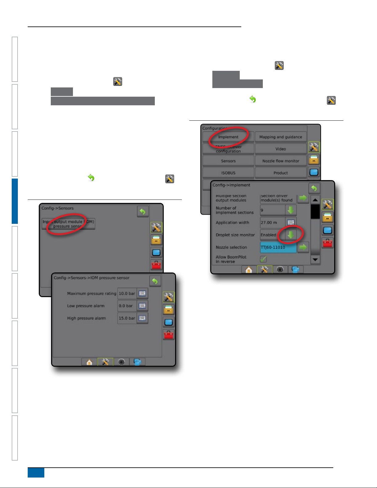
Input/output module pressure sensor
When a Pressure sensor interface kit is present, pressure sensor
options are used to enter the sensor manufacture's maximum
pressure rating and set high and low user determined pressure
alarms.
1. Press CONFIGURATION side tab .
2. Press
HOME GUIDANCEFULL SCREEN IMPLEMENTINTRODUC TION GNSS RATE CONTROL APPENDIXSETUP
3. Press
4. Select from:
5. Press RETURN arrow or CONFIGURATION side tab to
Figure 4-20: Input/output monitor pressure sensor options
Sensors .
Input output module (IOM) pressure sensor .
►Maximum pressure rating – used to establish the maximum
pressure rating of the pressure sensor as recommended by
the manufacturer
►Low pressure alarm – used to enter the user determined low
pressure point at which the alarm will sound
►High pressure alarm – used to enter the user determined high
pressure point at which the alarm will sound
return to the main Conguration screen.
Droplet size monitor
If a Pressure sensor interface kit is being used, the Droplet size
monitor options will be available.
1. Press CONFIGURATION side tab .
2. Press
3. Press
4. Select if droplet size monitor is enabled or disabled.
5. Press RETURN arrow or CONFIGURATION side tab to
Figure 4-21: Droplet size monitor
Implement .
Droplet size monitor .
return to the main Conguration screen.
22
www.teejet.com
 Loading...