

www.teejet.com
USER GUIDE
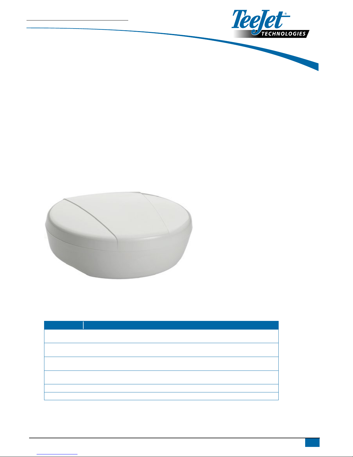
Thank you for choosing TeeJet Technologies’ RX520 as your GNSS receiver solution. This document provides instructions for mounting
and operation of the RX520. Contact a local dealer for more information or visit www.teejet.com.
Integrated GNSS Design
The RX520 provides an integrated L1/L2 GPS+GLONASS receiver and antenna in a single compact enclosure. Designed to meet or exceed stringent MIL-
STD-810G specications, the RX520’s rugged housing ensures high performance even in the most challenging work environments.
Multi-Constellation for Enhanced Positioning
Capable of tracking L1, L2 GPS+GLONASS and L-Band, the RX520 improves position availability in obstructed sky conditions.
Dual-frequency tracking minimizes the impact of ionospheric disturbances further enhancing eld productivity. Optional L-Band tracking improves
positioning accuracy outside of L1 SBAS coverage areas.
Smooth, Pass-to-Pass Accuracy with ClearPath® Technology
ClearPath technology is integrated into every RX520 antenna. ClearPath uses very accurate carrier phase calculations to provide ultra smooth positions
and excellent pass-to-pass accuracy for agricultural applications. ClearPath functions autonomously and with most available corrections services. It
will also bridge through short periods of poor satellite availability. ClearPath’s steady, smooth output is especially well suited for manual guidance and
autosteer installations.
BENEFITS
• Scalable for current dual constellation and future GNSS
systems
• Dual-frequency performance
• Smooth, consistent positions for pass-to-pass accuracy
• Rugged design for on-machine applications
FEATURES
• GPS and GLONASS satellite capability
• Built-in magnets for easy mounting
• Compatible with 12 V to 36 V vehicle power
• Ready to connect to any TeeJet Matrix, Matrix Pro, or
Aeros system. Matrix and Matrix Pro systems will require the
Power/CAN/Data cable [part number 45-05626 or
45-05845]
RX520 Options
Kit/Part Number Description
90-02893 GNSS Receiver RX520, L1/L2, ClearPath, Autonomous [78-50207].
Includes Mounting Bracket [65-05243] and RX520 to Power & Serial Com1 Cable [45-05957].
90-02894 GNSS Receiver RX520, L1/L2, ClearPath, SBAS [78-50208].
Includes Mounting Bracket [65-05243] and RX520 to Power & Serial Com1 Cable [45-05957].
90-02895 GNSS Receiver RX520, L1/L2, ClearPath, SBAS, PPP [78-50209].
Includes Mounting Bracket [65-05243] and RX520 to Power & Serial Com1 Cable [45-05957].
90-02899 GNSS Receiver RX520, L1/L2, ClearPath, PPP [78-50206].
Includes Mounting Bracket [65-05243] and RX520 to Power & Serial Com1 Cable [45-05957].
65-05243 Mounting bracket
45-05957 Cable, RX520 to Power & Serial Com1
RX520
L1/L2 GNSS RECEIVER AND ANTENNA
98-01491-EN R1
USER GUIDE
GETTING STARTED
This guide will assist in the set-up and operation of the RX520 GNSS receiver. The receiver will arrive ready to operate in the conguration that
was ordered. No further conguration will be required by the user. When the receiver is properly mounted with a clear view of the sky, and with the
connections for data and power completed, the unit will begin to provide positions. If using only GNSS (non L-band) solutions, position data will be
output within a few minutes of power-up. Allow approximately 15 minutes for quality SBAS positions and 20 minutes for PPP positions to be available.
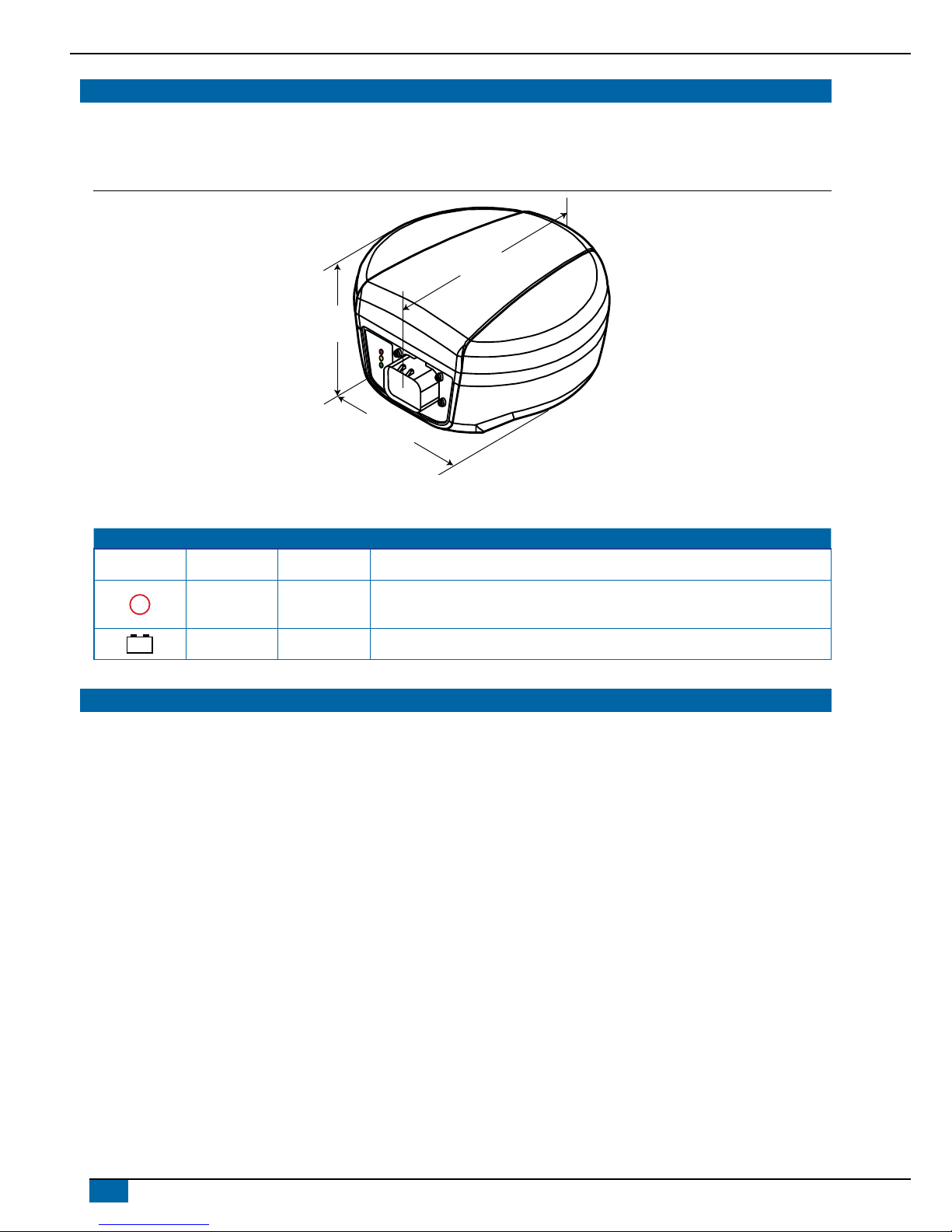
Figure 1: RX520 dimensions
155,0 mm
80,9 mm
155,2 mm
RX520 LEDs
LEDs on the front of the RX520 provide basic receiver status information. The operation of the LEDs on the RX520 is summarized in the following table:
Icon LED Color State Description
Green Position Valid Indicates a valid GNSS position solution is available
!
Yellow Error
Receiver is in the error state and tracking is disabled
NOTE: Error status remains until the cause of error is corrected and receiver is reset.
– +
Red Power Power is on
LBAND SUBSCRIPTION
To subscribe to the Terrastar subscription L-band service:
1. Note the serial number of your RX520, the part number of the subscription that you intend to purchase, and the date that you want your subscription to
be activated.
2. Ask your dealer to contact TeeJet customer support for the TerraStar Subscription bulletin [98-01494] and provide this information. Your dealer will send
the order to TeeJet, and your nancial transaction will take place between you and your dealer.
NOTE: The minimum lead time for activation is 72 hours.
Your receiver does NOT need to be powered on at the time the subscription becomes active. The rst time you power your receiver on after the specied
activation date, it will become active on the subscription you have requested within several hours. During subsequent operation of your receiver, it will
typically require 15 minutes of operation with a clear view of the sky to fully process the L-band correction data and provide a GGA quality indicator value
of "5".

5.0 in
127.0 mm
Ø0.27 in ± 0.01 in drill thru x 4
Ø6.858 mm ± 0.01 mm drill thru x 4
6.25 in
158.75 mm
0.50 in x 4
12.7 mm x 4
0.50 in x 4
12.7 mm x 4
This side will route
toward back of vehicle
www.teejet.com
TEEJET TECHNOLOGIES
MOUNTING INSTRUCTIONS
The RX520 is equipped with four (4) built-in magnets for attaching to the included mounting bracket. The mounting bracket can be secured to the base
surface using traditional fasteners.
Intermediate Mounting Plate Template
A template for the intermediate mounting plate has been drawn in the
background of this user guide.
• Red lines indicate holes where attachment will occur.
• Green lines indicate the outline of the mount and other holes for
attaching the release plate.
Mounting Considerations
• Choose a location that has a clear view of the sky so that each satellite
above the horizon can be tracked without obstruction.
• When mounting the RX520 Receiver, a space of at least 15 cm between
the receiver and any bend in the cable is required. Any length shorter
than 15 cm puts undue stress on the cable and the enclosure for the
RX520.
• The receiver should not be mounted where water can pool around it.
The receiver housing is designed to withstand rain and splashing, but
not submersion in liquids for sustained periods of time.
• Mount the receiver above all other metal objects to avoid multipath.
Satellite signals received by the GNSS receiver by a reection from an
object can decrease positioning accuracy. For example, roof racks, large
headlight enclosures, etc., can cause multipath that may result in a jump
in GNSS position.
Figure 2: Mounting Plate
Figure 3: Orientation Example
Route cable toward
the back of vehicle
Orient toward
the front of vehicle

98-01491-EN-A4 R1 English-international
© TeeJet Technologies 2014
USER GUIDE
www.teejet.com
SPECIFICATIONS
Performance
1
Channel Conguration ...................120 channels
2
Signal Tracking
GPS .................................................... L1, L2, L2C
GLONASS .................................................. L1, L2
Galileo .............................................................. E1
BeiDou .............................................................. B1
SBAS
3
L-Band
Horizontal Position Accuracy (RMS)
Single Point L1 ............................................ 1.5 m
Single Point L1/L2 ....................................... 1.2 m
SBAS ........................................................... 0.6 m
DGPS .......................................................... 0.4 m
NovAtel CORRECT™
TERRASTAR-D4 .......................................6 cm
RT-2® ...........................................1 cm + 1 ppm
Measurement Precision (RMS)
Fully independent code and carrier measurements
GPS ..........GLONASS
L1 C/A Codes ...................... 4 cm ................. 15 cm
L1 Carrier Phase ............ 0.5 mm ...............1.5 mm
L2 P(Y) Code
5
..................... 8 cm ................... 8 cm
L2 Carrier Phase5 ........... 1.0 mm .............. 1.5 mm
L2C Code6 .......................... 8 cm ................... 8 cm
L2C Carrier Phase6 ......... 1.0 mm ............... 1.5 mm
Maximum Data Rate
7
Measurements ................................... Up to 50 Hz
Position .............................................. Up to 50 Hz
Time to First Fix
Cold Start
8
......................................<50 s (typical)
Hot Start
9
........................................ <35 s (typical)
Signal Reacquisition
L1..................................................... 0.5 s (typical)
L2...................................................<1.0 s (typical)
Velocity Accuracy
10
.......................0.03 m/s RMS
Time Accuracy
11
.................................20 ns RMS
Physical and Electrical
Dimensions ..............................155 mm diameter
.................................................80.9 mm height
Weight ....................................................... <550 g
Connector ........................... 14-pin Tyco Ampseal
Mounting ............................. 2 x magnetic mount,
........................................4 x M4 screw inserts,
................................... Optional mounting plate
Power
Input Voltage Range ......................+8 to +36 VDC
Power Consumption .................... 2.9 W (typical)
12
Status LEDs ............. Power, Error, Position Valid
Power Input and I/O Protection
.............................................. ISO 7637-2:2004
........................................................ ISO 15003
Emissions and Immunity
......ISO 14982: EMC for Agriculture machinery
Environmental
Temperature
Operating ........................................-40°C to 75°C
Storage ...........................................-55°C to 90°C
Humidity ............... MIL-STD-810G Method 507.5
Immersion ............ MIL-STD-810G Method 512.5
Shock .................... MIL-STD-810G Method 516.6
Solar Radiation ......................... EN60950-22 8.2
.......................... MIL-STD-810G Method 505.5
Salt Fog ................ MIL-STD-810G Method 509.5
Sand and Dust ..... MIL-STD-810G Method 510.5
Vibration
Random ...........MIL-STD-810G, Method 514.6E-1
Sinusoidal ......... ASAE EP455, 5.15.2 Level 1 & 2
Compliance ......................................FCC, IC, CE
Ingress Protection Rating ........................... IP67
Warranty
1 year from Date of Purchase
Electrical Connection
Connector Pin-outs
Figure 4: Connector Pin-outs
Pin ....................................................................Use
1 ...........................................................COM1TxD
2 .......................................................... COM1RxD
3 ...........................................................COM2TxD
4 .......................................................... COM2RxD
5 ......................... Signal Ground (COM/MKI/PPS)
6 ..................................................................CAN+
7 ...................................................................CAN-
8 ...........................................................COM3TxD
9 ...................................... Power Negative/Return
10 .......................................................... Reserved
11 ............................................... MKI (Mark Input)
12 ...................... PPS (Pulse Per Second) Output
13 ........................................................ COM3RxD
14 ..................................... Power Positive/Source
1. Typical values. Performance specications subject to
GNSS system characteristics, US DOD operational
degradation, ionospheric and tropospheric
conditions, satellite geometry, baseline length,
multipath effects and the presence of intentional or
unintentional interference sources.
2. Tracks up to 60 L1/L2 satellites.
3. GPS only.
4. TERRASTAR-D subscriptions are available from
TeeJet.
5. L2 P for GLONASS.
6. L2 C/A for GLONASS.
7. 50 Hz while tracking up to 20 satellites.
8. Typical value. No almanac or ephemerides and no
approximate position or time.
9. Typical value. Almanac and recent ephemerides
saved and approximate position and time entered.
10. Export licensing restricts operation to a maximum of
515 meters per second.
11. Time accuracy does not include biases due to RF or
antenna delay.
12. Power consupmtion values for GPS L1/L2.
 Loading...