

TED 1001 Installation And Operation Manual
I n s t a l l a t i o n
a n d
O p e r a t i o n s
M a n u a l

© 2008 Energy, Inc. www.theenergydetective.com
Page 2
N O T I C E - I M P O R T A N T
TED MODEL 1001 OPERAT I O N A L LIMITATIONS
• TED Model 1001 is only suitable for use on 120/240V single-phase 60Hz services
• TED Model 1001 is only suitable for services of 200 AMPS or less. (For 400 amp service,
see website for details on TED Model 1002)
• TED Model 1001 is only suitable for use with services with a single service disconnect
(For services with two disconnects, see website for details on TED Model 1002)
• TED Model 1001 is only suitable for services with maximum 350 MCM Conductors
• TED Model 1001 RDU is only approved for use with the following TED accessories:
• TED Model 1001 MTU (Measuring Transmitting Unit)
• TED Model QX 200-CT (Current Transformers)
Use with any other product will void warranty, and may cause an electrical or re hazard.
SAFE OPERATING RANGE AND CONDITIONS:
Use
Temperature
Relative Humidity
Altitude
Voltage
Indoor/Dry
10° - 40°C
< 80%
< 3,000M
100-130 V
RDU
Indoor/Outdoor Dry
5° - 40°C
< 90%
< 3,000M
100-130 V
MTU CT’s
Indoor/Outdoor Dry
5° - 40°C
< 90%
< 3,000M
100-600 V
If any of the following are true, this version of TED WILL NOT work:
• If you have a 3-Phase service, TED Model 1001/1002 WILL NOT work.
• If you have 230V 50Hz service typical in most areas outside North America, TED Model
1001/1002 WILL NOT work.
• If your main circuit breaker or fuse panel is larger than 200 Amps, TED Model 1001 WILL
NOT work. If it is 400Amps or less, TED Model 1002 is suitable.
• If you have more than one main circuit breaker or switch, TED Model 1001 WILL NOT
work. If you have 2 Main Circuit Breakers of 200Amps each, TED Model 1002 is suit-
able.
• If your main service circuit conductors (wires) are larger than 1-inch diameter, TED Model
1001/1002 WILL NOT work.
• Other TED models will be available soon for these applications. Please see our web site
for details.

Energy, Inc. • 3297 Pacific Street • Charleston, South Carolina 29407 • (843) 766-9800
Page 3
T A B L E O F C O N T E N T S
Introduction . . . . . . . . . . . . . . . . . . . . . . . . . . . . . . . . . . Page 4
Safety . . . . . . . . . . . . . . . . . . . . . . . . . . . . . . . . . . . . . . . Page 6
Quick Start Installation . . . . . . . . . . . . . . . . . . . . . . . . . Page 7
(For Electricians and Professional Installers ONLY)
Programming TED . . . . . . . . . . . . . . . . . . . . . . . . . . . . Page 12
Day-to-Day Operation . . . . . . . . . . . . . . . . . . . . . . . . . Page 17
Viewing Historical Data . . . . . . . . . . . . . . . . . . . . . . . . Page 21
Setting Alarms . . . . . . . . . . . . . . . . . . . . . . . . . . . . . . . Page 22
Special Functions . . . . . . . . . . . . . . . . . . . . . . . . . . . . Page 24
PART I
PART II
PART III
PART IV
PART V
PART VI
PART VII
A P P E N D I C E S
Detailed Installation Instructions . . . . . . . . . . . . . . . . . . Page 25
Troubleshooting Guide . . . . . . . . . . . . . . . . . . . . . . . . . Page 31
No Spare Circuit Breaker . . . . . . . . . . . . . . . . . . . . . . . . Page 34
Understanding Your Electricity Bill . . . . . . . . . . . . . . . . . Page 35
FAQ - Frequently Asked Questions . . . . . . . . . . . . . . . . Page 36
A.
B.
C.
D.
E.

© 2008 Energy, Inc. www.theenergydetective.com
Page 4
I N S TA L L A T I O N
A N D
O P E R A T I O N S M A N U A L
P A R T I – I N T R O D U C T I O N
TED is a new and innovative product designed to provide residential and small business
owners with up-to-the-minute energy use and cost information. Electricity is one of the few
products we purchase, for which we don’t know the cost until weeks after we have used
it. Until the development of TED, you would only nd out the actual cost of the electricity
purchased after the bill arrived in the mail...far too late to do anything about it.
TED is an extremely accurate, precision device. Certain factors, however, such as the date
and time the utility meter is read, the distance between the utility meter and electric panel,
as well as other variables will result in monthly totals recorded by TED being slightly differ-
ent than those measured by your electric utility. Therefore TED may never exactly match
your utility bill.
TED displays up-to-the-minute energy use and cost information in an easy-to-read and
understand format.
• Current energy consumption in kilowatts (kW).
• Current energy cost in dollars and cents per hour ($/hr).
• Energy consumed so far today in kilowatt-hours (kWh).
• Energy cost so far today in dollars and cents ($).
• Energy consumed so far this billing cycle in kWh.
• Energy cost so far this billing cycle in $.
• Projected energy use for current billing cycle in kWh.
• Projected energy cost for current billing cycle in $.
• Peak electrical demand so far this billing cycle in kW.
• Peak use so far this billing cycle in $/hr
• Current voltage in Volts (V)
• Minimum voltage this billing cycle in Volts (V)
• Maximum voltage this billing cycle in Volts (V)
• Current Energy Rate (Tariff) in dollars and cents per kilowatt hour $/kWh
• Current Date & Time
• Timer
• Alarms
• Historical Data for 12 months
TED transmits energy data from the main electric service panel to the display unit over exist-
ing power lines, thus no new wiring is required. TED measures true RMS energy use.
Energy, Inc. • 3297 Pacific Street • Charleston, South Carolina 29407 • (843) 766-9800
Page 5
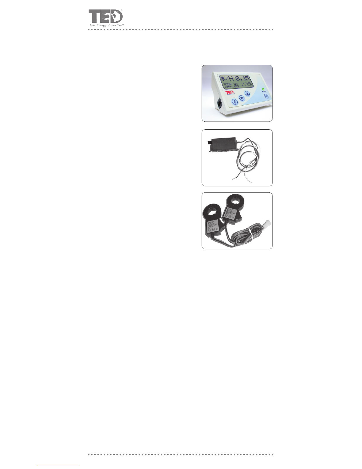
Unpacking
Unpack TED and insure that all parts are included in the package.
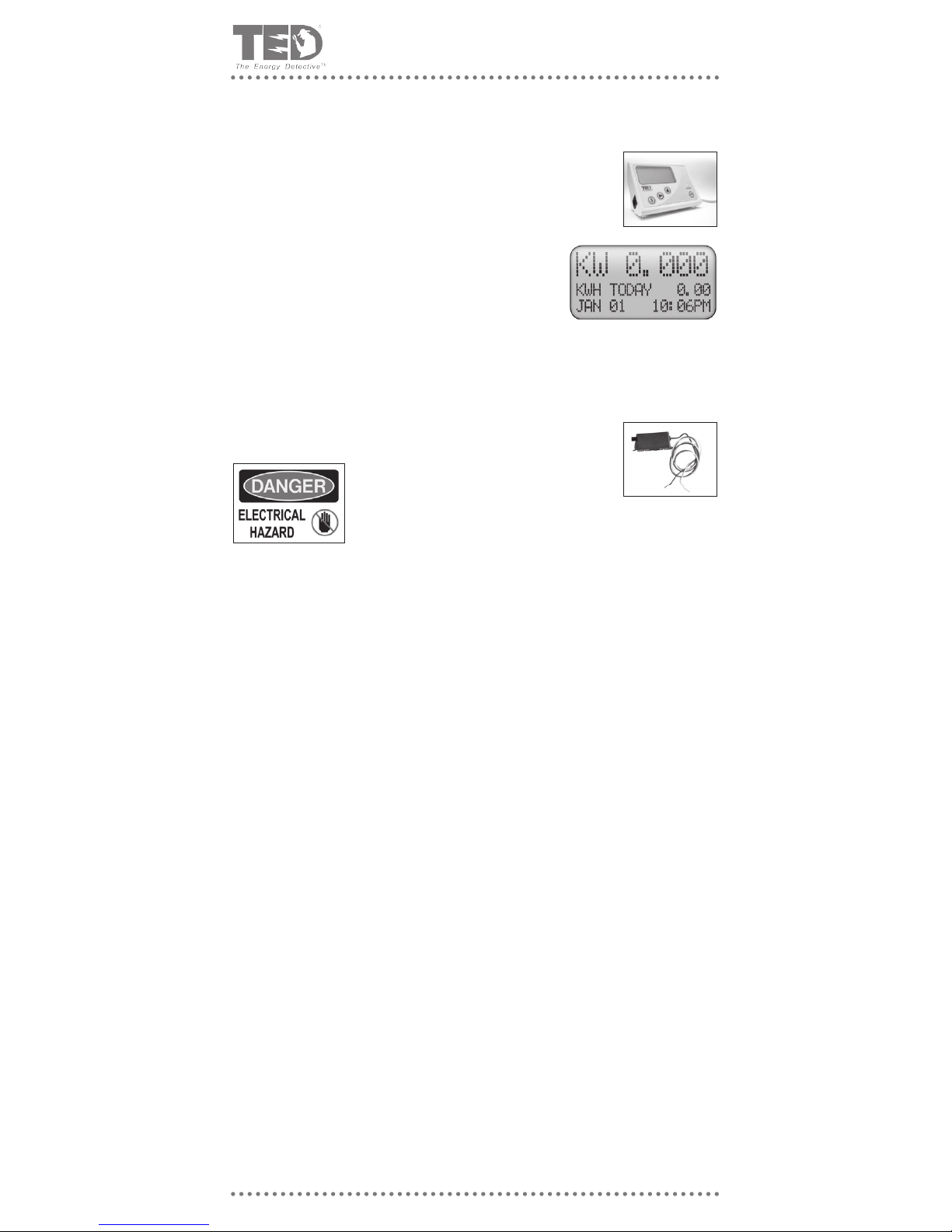
a) One (1) Model 1001 Receiving Display Unit
(RDU) - The unit comes with the angled stabilizing
stand attached, so it will sit in a viewable position
on any counter top; for ush or wall mounting, the
stabilizing stand can be easily removed for wall-
mounting.
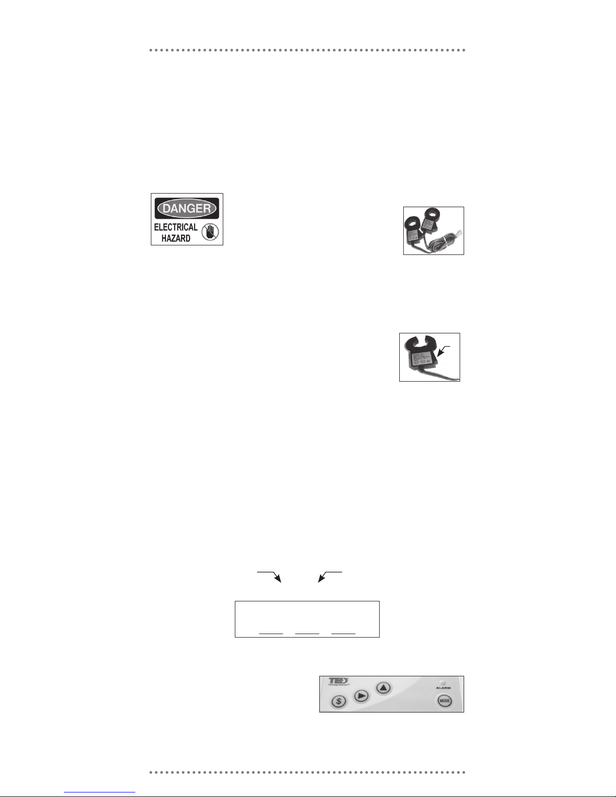
b) One (1) Model 1001 Measuring Transmitting Unit
(MTU)
c) Two (2) Model QX200CT Current Transformers
(CT’s)
d) Instruction Manual - Please Read Carefully
e) Warranty Card
© 2008 Energy, Inc. www.theenergydetective.com
Page 6
P A R T I I – S A F E T Y
Every effort has been made in providing for the safe, secure installation of TED. The instal-
lation of TED requires the cover of the main electrical circuit breaker panel to be removed.
When this is done, there exists the potential hazard of shock, burn, or even electrocution.
Do not attempt to complete this installation unless you are very familiar with the electri-
cal components and operation of the circuit breaker panel. Even when the Main Circuit
Breaker has been turned to the “OFF” position, there may still be areas within the circuit
breaker panel that may be electried. Do not attempt installation unless you know where
these areas are.
WARNING - These servicing instructions are for use by Qualied Personnel only. To reduce
the risk of electric shock, DO NOT perform any servicing other than that contained in these
operational instructions, unless you are qualied to do so.
WARNING - The MTU must be connected to a switch or circuit breaker in close proximity
to the equipment and within easy reach of the operator. It must be marked as the discon-
necting device for the MTU.
WARNING - If the equipment is used in a manner not specied in these instruction, the
protection provided by the equipment may be impaired.
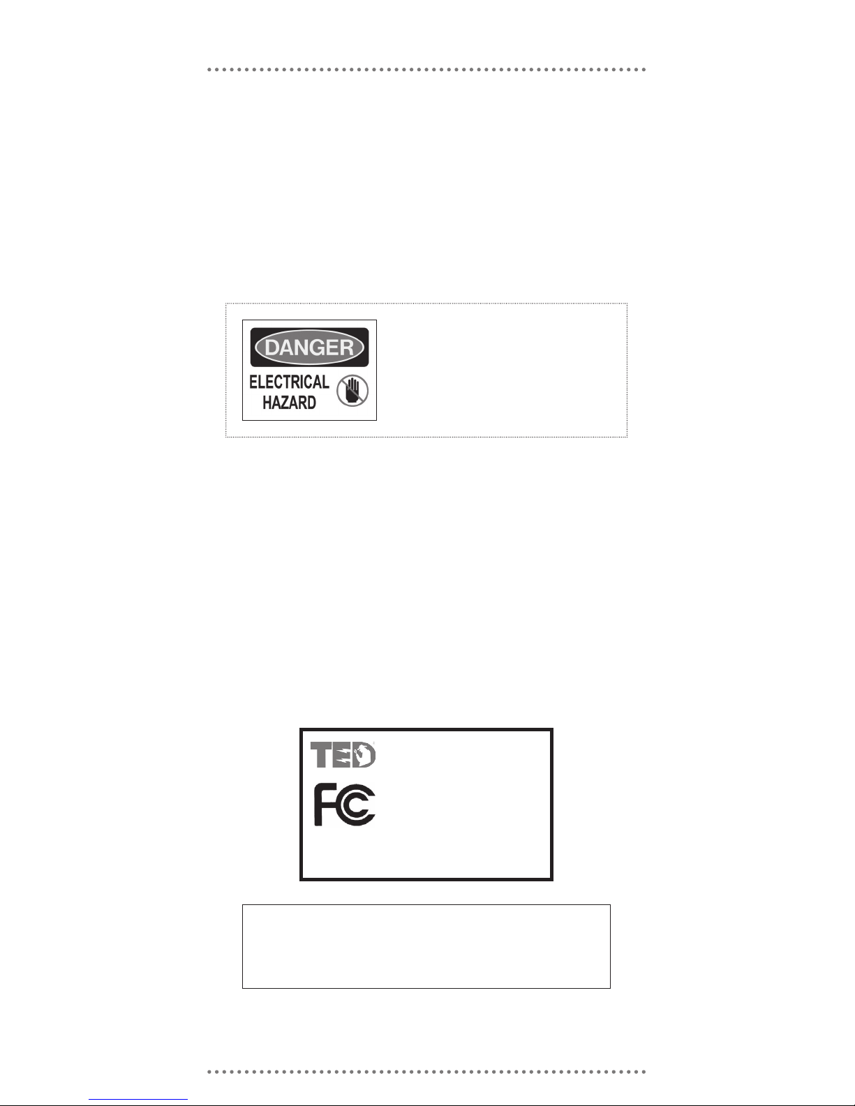
This symbol will be found throughout the in-
structions where there is a potential for elec-
tric shock, burn, or even electrocution. Do not
attempt to complete the noted section if you
are not an electrician, or qualied installer.
Model 1001 / Model 1002
TESTED TO COMPLY WITH
FCC STANDARDS
FOR HOME AND OFFICE USE
This device complies with part 15 of the FCC Rules. Operation is subject
to the following two conditions: (1) This device may not cause harmful
interference, and (2) This device must accept any interference received,
including interference that may cause undesired operations.

Energy, Inc. • 3297 Pacific Street • Charleston, South Carolina 29407 • (843) 766-9800
Page 7
P A R T I I I – Q U I C K S T A R T I N S T R U C T I O N S
• Do not begin installation until you have read ‘Part II - Safety’
• Read all Instructions before beginning installation
Estimated Installation Time:
Professional Installer: 15 – 30 minutes
Equipment Needed:
Flathead screwdriver - small and large
Phillips screwdriver - small and large
Flashlight
QUALIFIED ELECTRICIANS OR PROFESSIONAL INSTALLERS FAMILIAR WITH ALL
ASPECTS OF ELECTRICAL WIRING AND THEORY, MAY USE THE FOLLOWING CON-
DENSED INSTRUCTIONS FOR INSTALLATION OF TED.
ALL OTHERS SHOULD FOLLOW THE DETAILED INSTRUCTIONS IN APPENDIX A.
This model of TED is suitable for installation on a single 120/240V single phase 60Hz ser-
vice, normally found in North America (USA, Canada, Mexico and portions of the Carib-
bean). It is not suitable for three-phase service, for service where there are two or more
main circuit breakers or for 230V 50Hz service commonly found in other regions of the
world. Other models of TED are available for these applications. Please refer to our TED
Web site:
www.theenergydetective.com
All wiring in the United States must be installed in accordance with the latest adopted edition
of the National Electrical Code (ANSI/NFPA 70, NEC) and state or local requirements. All
wiring in Canada must be installed in accordance with the latest adopted edition of the Ca-
nadian Electrical Code (CSA C22.2 CEC, Part I) and any provincial or local requirements.
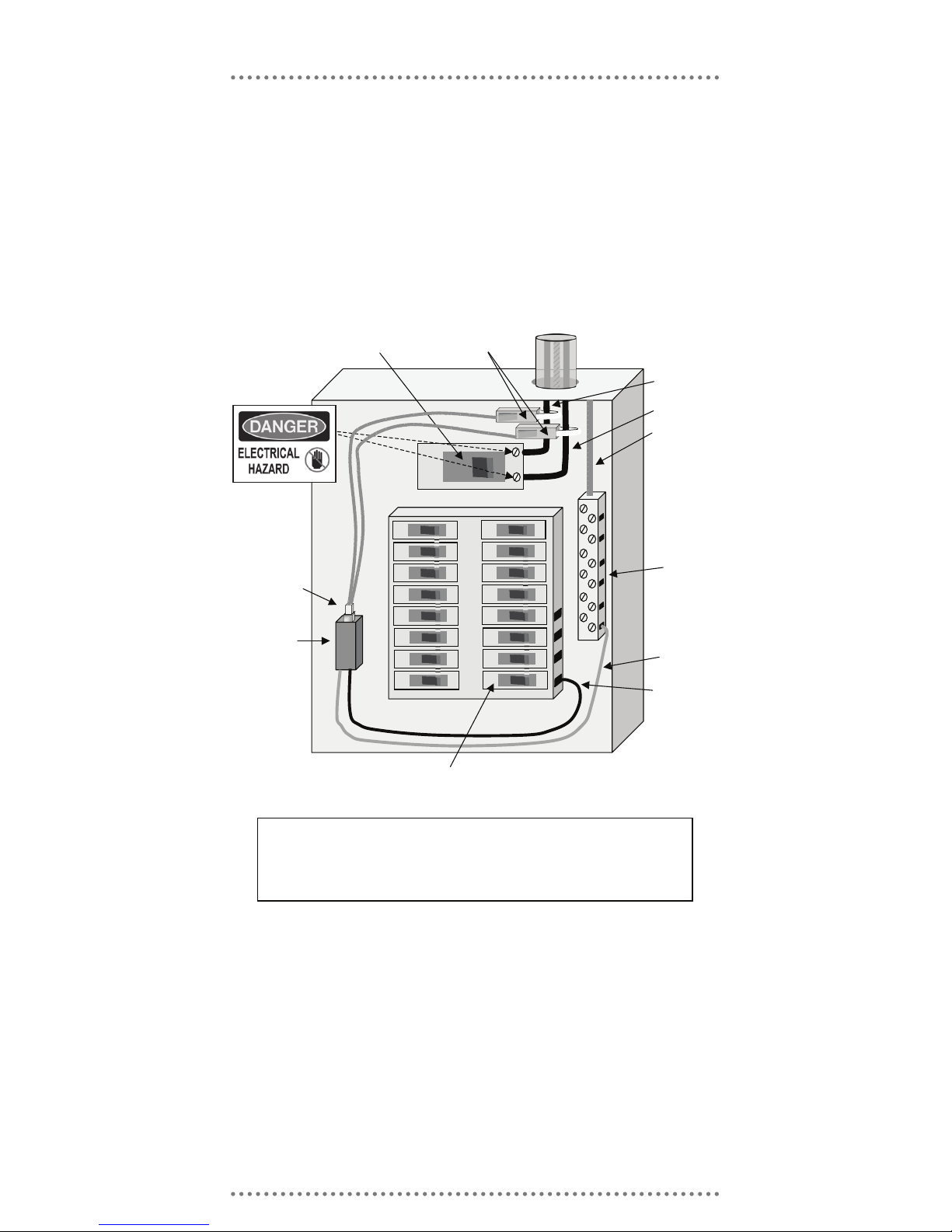
MTU
Neutral
Phase B
Phase A
Inc oming Power Li nes
120/240 V
MA X 200A
Connector
White
Black
Neutral
Bus
15 or 20A
Circuit Breaker
CT’s
Fig. 3
Installing MTU
Typical Combination Circuit Breaker Panel
Main Circuit Breaker
MAX 200A
© 2008 Energy, Inc. www.theenergydetective.com
Page 8
Energy, Inc. • 3297 Pacific Street • Charleston, South Carolina 29407 • (843) 766-9800
Page 9
Quick Start
STEP 1 - INSTALLING THE RECEIVING DISPLAY UNIT (RDU)
A) Determine a suitable location and plug the RDU into a standard
120V, 15 or 20-amp outlet
• Suggestion: the kitchen counter or other convenient location
B) The RDU should be displaying all zeroes and the LED
should not be ashing. If not, another TED may be trans-
mitting on the line. Refer to Troubleshooting Section.
• If the RDU is in $ display-mode, press ‘$’ Key to change to
KW display mode.
STEP 2 - INSTALLING THE MEASURING TRANSMITTING UNIT (MTU)
(Refer To FIG 3)
TURN OFF ALL POWER TO THE CIRCUIT BREAKER PANEL BY
TURNING OFF THE MAIN BREAKER OR MAIN SWITCH.
A) Turn off power.
B) Remove panel cover.
C) Determine best location to mount MTU.
• Choose location where it will not interfere with existing equipment or wiring.
• The MTU may be attached using double-sided tape (if allowed in your jurisdiction), or
with sheet metal or machine screws.
• Sticky Black Tape
• Install two pieces of sticky back tape to backside of MTU
• Insure surfaces are clean
• Press MTU rmly into place
• Screws
• Drill pilot holes in required location
• Attach with Sheet-Metal screws if ush-mounted.
• Attach with Machine Screws and Nuts if surface-mounted.
D) Connect the black wire from the MTU to a spare 15 or 20-A circuit breaker in the panel.
Note: In Canada it must be connected to a 15A circuit breaker. Mark the panel directory
to indicate that this circuit controls the MTU.
• Note - The circuit breaker (15 or 20A) provides over current protection and a disconnect-
ing means for the MTU. Failure to provide a properly sized circuit breaker is a violation
of NEC and CEC.
• Note: This should be connected to a circuit breaker on the same phase as the recep-
tacle that the RDU is plugged into.
• Note: The wire is stranded but it is tinned which will make it seem like installing a solid
conductor.
• If there is no spare circuit breaker refer to Appendix C on page 34.
E) Connect the white wire from the MTU to the neutral bus on the panel.
Press
Here
Serial No.House Code
Fill in your
House Code
here:
© 2008 Energy, Inc. www.theenergydetective.com
Page 10
STEP 3 - INSTALLING AND CONNECTING THE CT’S
A) CAUTION – IF THIS IS A COMBINATION PANEL, THE LUGS ON THE PRIMARY
SIDE OF THE MAIN BREAKER ARE PROBABLY STILL HOT. The CT’s must be
installed with the red polarity dots either both facing towards the main breaker, or both
away from the main breaker to maintain the correct polarity. If both CT’s are not in-
stalled in this manner, the readings will be wrong.
• Note: Do not install the CT over the neutral (N) (grounded) conductor.
B) Install one of the Current Transformers (CT’s) over each incoming power line Phase
A or B, by pressing on the handle to open the split core CT and
then clipping it over the power lines as shown in
Fig 3. Preferably, they should be installed on the
secondary side of the main switch or main circuit
breaker, however if this is not possible, such as in the case of a com-
bination breaker panel, then install on the primary side of the main breaker.
• Insure that the 2 sides of the split core CT’s are mated tightly together
C) Connect the CT’s to the MTU by plugging the plastic mating connectors together.
• Note: The connectors are polarized and can only be inserted one way. Do not force.
D) Arrange and tie-wrap all wiring in a neat and tidy manner.
E) Turn the power back on.
F) Conrm that the green LED on the MTU is ashing approximately
once-per-second. If not, check MTU installation or refer to Trouble-
shooting Section in Appendix B.
STEP 4 - SETTING THE HOUSE CODE
NOTE: TED’s display unit can possibly receive data from other TED MTU’s con-
nected to the secondary side of the same utility transformer. To guard
against reading your neighbor’s electricity use, each MTU has a House
Code from 000 to 255. This number can be found in two places: on a sticker
on the MTU, and on a sticker included loose with the MTU. Place this
sticker on the outside of the panel for future reference. The House Code is
the three-digit number preceding the Serial Number. In the example below
the House Code is 137.
TO SET THE HOUSE CODE:
The RDU has 4 buttons on the front
labeled $, u, p, and “MODE”.
137B-15509741
Energy, Inc. • 3297 Pacific Street • Charleston, South Carolina 29407 • (843) 766-9800
Page 11
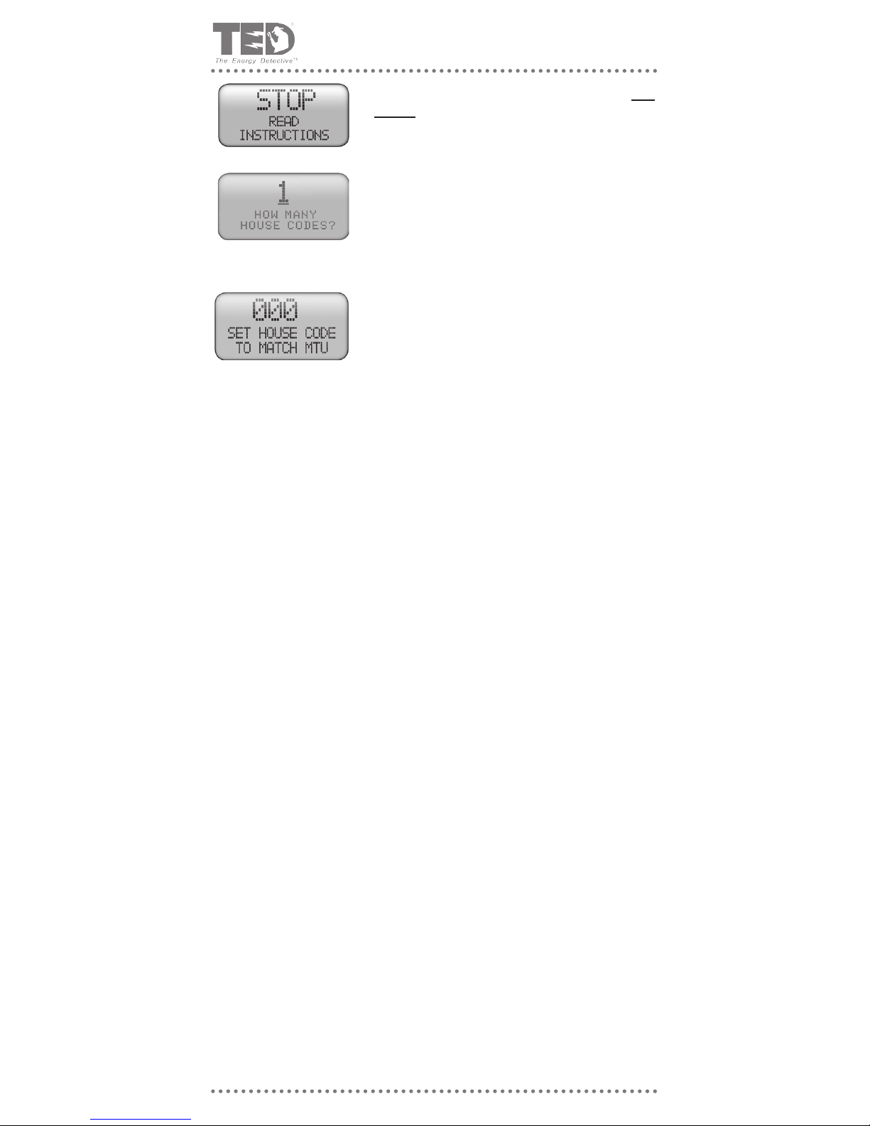
A. Hold the “$” and p keys down at the same time for 3
seconds and this screen should come up. You are reading
the instructions, so go ahead and press the MODE key to
go to the next screen.
B. If you have TED model 1001, you will only have 1 House
Code. Press the MODE key to go to the next screen. If
you have TED model 1002, please see the separate instructions included in your additional MTU box.
C. Use the ►and ▲ keys to change the “000” to match the
House Code that you noted above. Press the MODE key
when done. This will take you to the primary kW display
screen.
STEP 5 - CONFIRM PROPER OPERATION
A) Insure that the RDU is set to read kW and not $/Hr (by depressing the ‘$’ key if neces-
sary). NOTE: All $/Hr readings will read zero because the energy rate charge (tariff) has
not been input yet. This will be done later. Observe the RDU; it should now be showing
the current kW usage in the home or business. The LED on the front of the RDU should
be ashing green approximately every one second, indicating that data is being sent
and received properly.
B) If the reading is still 0 kW, check House Code Setting (See prior section on House Code
details - Page 10)
C) If the reading is still 0 kW, insure that the RDU and MTU are on the same phase. If not,
change the wiring in the panel so that they are, or install a phase-coupling capacitor.
If still not operating, see Troubleshooting Section. Check the polarity of the CT’s by
turning on a large 240V load such as an electric clothes dryer or oven. If the CT’s are
installed with the correct polarity, then the RDU will immediately register an increased
reading of 2–6 kW. If there is little or no change, then it is likely that one of the CT’s has
been installed backwards. Reverse one of the CT’s and try again.
D) The kW reading can be checked by comparison with a good clamp-on multi meter. Turn
off any appliances that cycle on and off automatically to obtain a constant reading (the
higher the reading the better – turn on all the lights and other constant loads). Measure
the voltage from phase to neutral (VL) and the current in each Phase (IA and IB). The
kW display should read very close to kW = VL x (IA +IB)/1001. If the reading is much
lower than this, check that the CT’s have been installed with the red dots facing the
same direction.
E) If still not working, refer to Troubleshooting - Appendix B.
F) Re-install the panel cover.
G) To program Utility rates in the RDU, refer to Part IV.
© 2008 Energy, Inc. www.theenergydetective.com
Page 12
P A R T I V - P R O G R A M M I N G T E D 1 0 0 1
Estimated Programming Setup Time:
Home Owner: 10 – 30 minutes
Professional Installer: 5 – 10 minutes
PROGRAM TED AFTER THE PREVIOUS INSTALLATION PROCEDURES ARE
COMPLETE.
TED is designed so that the SETUP MODE need only be accessed upon initial setup, or
when the Utility has a rate change, or when the user wants to modify any of the opera-
tional information – time and date, billing date, etc. The entered data will stay intact when
unplugged or there is a power outage. As data is entered during the SETUP MODE, it is
permanently stored once the MODE Key is pressed; to change data after the initial setup
routine, simply repeat the Setup procedure.
• To move from digit-to-digit within a eld, depress the u key;
• To change the value, depress the p arrow (press once to advance one digit, or hold
down to keep advancing);
• To move from one eld to another, depress the MODE Key. (HOLDING DOWN the
MODE Key will Save and Exit to the main display – this should be done only when
changes are complete).
• Have a copy of your most recent Electricity Bill nearby to obtain information from...you
will need it.
• Refer to Appendix E “Understanding Your Electric Bill”, or Appendix F - FAQ if you are
not sure how to enter your Setup Information .
SETUP MODE
(DEPRESS AND HOLD $ AND MODE KEYS SIMULTANEOUSLY FOR 2 SECONDS)
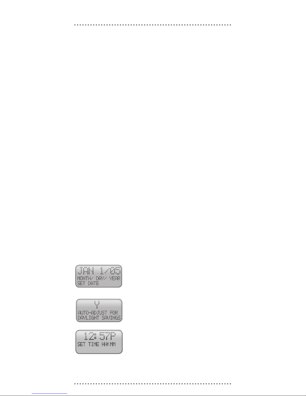
Use the u and p keys to change the date, then press the
MODE Key.
If your locale observes Standard North American Daylight
Savings Time, choose “Y” otherwise choose “N.” Use the
▲ key to toggle between “Y” and “N” and then press the
MODE key. TED will automatically adjust the time based
on the New Daylight Savings Time standard passed by
US Congress in 2006.
INPUT DATE AND TIME
INPUT METER-READ DATE
This information is found on your utility bill. The Meter Read Date generally will fall on the
Use the u and p keys to change the time, then press the
MODE Key. Be CERTAIN to get the AM / PM correct.
 Loading...