


COLD WEATHER
CWT INDIRECT HEATING BOILER
OPERATOR MANUAL | BOILER VERSION | 2016
PN :: HEA -BOI -MANUAL -016 | 20170316
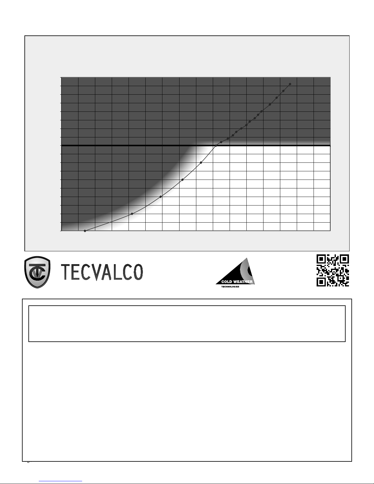
Boiling Point of Water at various Pressures Gauge Pressure
(Vacuum and Positive Pressure)
20
17.5
15
12.5
10
7.5
5
2.5
0
-2.5
-5
-7.5
-10
-12.5
-15
-17.5
-20
-22.5
Steam Pressure (positive in PSI -negative in INHG)
-25
120 130 140 150 160 170 180 190 200 210 220 230 240 250 260 270 280
Boiling Point of Water Temperature Deg F
Low Vacuum Range
(Possible Leak)
Strong Vacuum
(Healthy Unit)
To use this chart correlate the
steam temperature gauge vs. the vacuum gauge reading.
For service
scan the QR code,
or call
(780) 875-2530
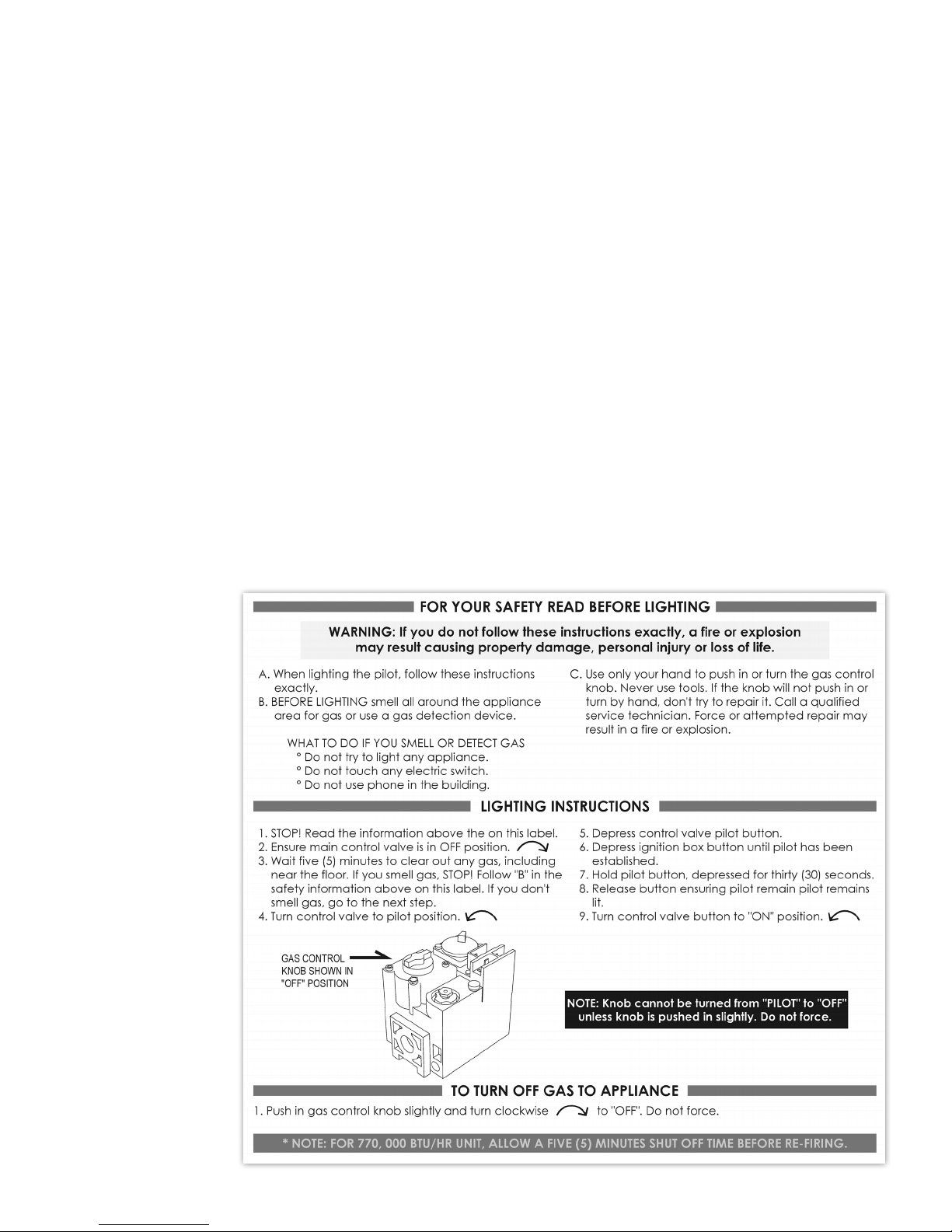
WARNING:
If the information in this manual is not followed exactly, a fire or explosion may result
causing property damage, personal injury, or loss of life.
Do not store or use gasoline or other flammable vapours and liquids in the vicinity of this or any
other appliance.
WHAT TO DO IF YOU SMELL GAS
= Do not try to light any appliance.
= Do not touch any electrical switch; do not use any phone in your building.
= Immediately call your gas supplier from a neighbour’s phone. Follow the gas supplier’s
instructions.
= If you cannot reach your gas supplier, call the fire department.
Installation and service must be performed by a qualified installer, service agency, or the gas
supplier.
Page 2
PN :: HEA -BOI -MANUAL -016 | 20170316

CWT (Cold Weather Technologies)
is an indirect-heater product line of
Tecvalco Ltd.
Niagara Falls, Ontario CANADA
Toll Free: 1 (866) 317-0131 | www.tecvalco.com
MODEL NUMBER: ____________________________________________
SERIAL NUMBER: _____________________________________________
COLD W E ATHER
IMPORTANT NOTES:
1) The installation must conform to the requirements of the authority having jurisdiction or, in the
absence of such requirements, to the National Fuel Gas Code, ANSI Z223.1/NFPA 54 and/or
CAN/CSA B149.1, Natural Gas and
Propane Installation Code.
2) Where required by the authority having jurisdiction, the installation must conform to the
Standard for Controls and Safety Devices for Automatically Fire Boilers, ANSI/ASME CSD-1.
3) Placement of the C WT DLH unit should be such that there are no combustibles or any
combustible construction within three feet (3’) of boiler, vent stack, and steam piping. Boiler unit
must not be installed on combustible floors.
4) The equipment shall be installed in accordance with the current Installation Code for Gas
Burning Appliances and Equipment, and applicable State Regulations for the class; which should
be carefully followed in all cases. Authorities having jurisdiction should be consulted before
installations are made.
5) The boiler and its individual shutoff valve must be disconnected from the gas supply piping
system during any pressure testing of that system at test pressures in excess of ½ psi (3.5 kPa).
The boiler must be isolated from the gas supply piping system by closing its individual manual
shutoff valve during any pressure testing of the gas supply piping system at test pressures equal
to or less than ½ psi (3.5 kPa).
6) The boiler shall be installed such that the gas ignition system components are protected from
water (dripping, spraying, rain, etc.) during appliance operation and service.
7) Provisions for combustion and ventilation air in accordance with the section “Air for Combustion
and Ventilation,” of the National Fuel Gas Code, ANSI Z223.1/NFPA 54, or Clause 8.2, 8.3 or 8.4
of Natural Gas and Propane Installation Code, CAN/CSA B149.1, or applicable provisions of the
local building codes.
PN :: HEA -BOI -MANUAL -016 | 20170316
8) This boiler is not connected /serviced as a common venting system.
9) Vent clearances will be for the Authority having Jurisdiction to determine the correct dimensions
for their site clearances.
10) ANSI Z21.13/CSA 4.9 requires a sediment trap to be installed upstream of the fuel train. End
users will need to make accommodation for a sediment trap in your piping upstream of fuel train.
11) Manual main shutoff valve location: The manual main shutoff valve is located before the Fisher
HSR regulator on the fuel train.
CAUTION: Label all wires prior to disconnection when servicing controls.
Wiring errors can cause improper and dangerous operation.
All wiring indicated within this manual shall be done in accordance with the NEC “National
Electrical Code” for US applications.
Verify proper operation after servicing.
This manual and the instructions outlined within apply to all CWT Heater Models ranging
from DLH-70 to DLH-4620
Page 3

FOREWORD
Foreword
Thank you for purchasing a Cold Weather Technologies (CWT) Indirect Heating
Boiler. The following manual has been simplified to give both technical and
non-technical owners and operators a detailed and thorough understanding of
CWT Heater operation. Detailed installation diagrams and pictures can also be
found inside this manual. These diagrams will serve you well as a reference for
the unit and its materials.
Please note: it is essential that all wiring and piping be installed in accordance
with this manual
The low pressure boilers supplied with the CWT Heaters are designed,
manufactured and registered as ASME Section IV Low Pressure Boilers. The
control systems are designed and installed in accordance with ASME CSD-1.
Local regulations may vary for installation, design and operator certification
requirements. Please review and comply with all local codes and regulations.
The boiler is designed to operate on natural gas. However, please ensure the gas
on which the boiler will operate is the same as that specified on the boiler model
and rating plate.
Some components in the Instrumentation might have been changed or
replaced due to market availability at the time when this manual was
prepared. However, a changed component does not affect the overall
capability of the CWT Natural Gas Heater. With proper care and regular
maintenance, the heater should provide years of trouble–free service. Please
take a few moments and read through the manual carefully. Keep the manual
in a safe place where it can be easily located if needed.
We welcome any suggestions from customers to help improve this product line,
please feel free to call CWT.
The CWT boiler and its components are designed, fabricated, tested and
inspected in accordance to the laws, codes, statutes and regulations for use in
the Province of Alberta, Canada. The end user is responsible for ensuring that
CWT boiler complies with all Federal, Municipal, Provincial, State and Local laws,
Codes, Statutes and Regulations prior to installation of the unit, and
application of permits, licenses, certificates and authorizations thereof.
Page 4
Warning: This manual must be read in its entirety before installation of this
product. Installation must be performed by a qualified technician and adhere to the
safety standards. Failure to do so will result in personnel injury or property damage.
PN :: HEA -BOI -MANUAL -016 | 20170316

TABLE OF CONTENTS
Table of Contents
Installation, operating and service manual SECTION A
Quality control documentation SECTION B
CAD drawings SECTION C
Material Safety Data Sheets SECTION D
PN :: HEA -BOI -MANUAL -016 | 20170316
Page 5

SECTION A CONTENTS
1. Introduction . . . . . . . . . . . . . . . . . . . . . . . . . Page 8
2. Site preparation and delivery . . . . . . . . . . . . . . . . Page 10
2.1 Prior to receiving the boiler . . . . . . . . . . . . . . . . Page 10
2.2 Upon receiving the boiler . . . . . . . . . . . . . . . . Page 11
2.3 Assembly procedures . . . . . . . . . . . . . . . . . . Page 11
3. Installation procedures . . . . . . . . . . . . . . . . . . . Page 12
4. Components, safeties and controls . . . . . . . . . . . . . Page 15
4.1 Boiler section . . . . . . . . . . . . . . . . . . . . . . Page 15
4.1.1 Swordfish burners (burner manifold or burner tray) . . . . Page 15
4.1.2 Pilot and thermopile assembly . . . . . . . . . . . . . . Page 16
4.1.3 The fintube assembly (primary heat exchanger) . . . . . . Page 17
4.1.4 The control box . . . . . . . . . . . . . . . . . . . . . Page 18
4.1.5 P and ID drawings . . . . . . . . . . . . . . . . . . . . Page 21
4.1.6 Flame or flash back arrestors . . . . . . . . . . . . . . Page 24
4.1.7 Robertshaw gas valve . . . . . . . . . . . . . . . . . . Page 25
4.1.8 Low fluid level switch . . . . . . . . . . . . . . . . . . Page 26
4.1.9 Low-low fluid level switch . . . . . . . . . . . . . . . . Page 27
4.1.10 Ignitor box and hand-held sparker . . . . . . . . . . . . Page 28
4.1.11 Pressure safety valve (relief valve) . . . . . . . . . . . . . Page 29
4.1.12 Operating steam pressure switch . . . . . . . . . . . . . Page 30
4.1.13 High-high steam pressure switch with ESD . . . . . . . . Page 31
4.1.14 Temperature control (line temperature control) . . . . . . . Page 32
4.1.14a 140 / 385 boiler line temperature controller . . . . . . . . Page 33
4.1.14b 770 boiler line temperature controller . . . . . . . . . . . Page 34
4.1.15 Fisher HSR regulator . . . . . . . . . . . . . . . . . . . Page 35
4.1.16 Pressure gauge WIC (inches of water column) . . . . . . . Page 36
4.1.17 Emerson 289H relief valve . . . . . . . . . . . . . . . . Page 36
4.1.18 Fuel train drawings . . . . . . . . . . . . . . . . . . . Page 37
4.1.19 Pressure vacuum gauge . . . . . . . . . . . . . . . . . Page 39
4.1.20 High-pressure coil gauge . . . . . . . . . . . . . . . . Page 40
4.1.21 Liquid level gauge . . . . . . . . . . . . . . . . . . . . Page 41
4.1.22 Exhaust vent . . . . . . . . . . . . . . . . . . . . . . Page 42
4.1.23 Emergency shutdown device . . . . . . . . . . . . . . . Page 43
4.2 Condenser section (heat exchanger) . . . . . . . . . . . Page 44
4.2.1 The heat exchanger can . . . . . . . . . . . . . . . . . Page 45
4.2.2 The high-pressure process coil . . . . . . . . . . . . . . Page 46
5. Start-up procedure . . . . . . . . . . . . . . . . . . . . . . Page 48
Page 6
6. Typical operation . . . . . . . . . . . . . . . . . . . . . . . Page 49
6.1 Glycol . . . . . . . . . . . . . . . . . . . . . . . . . Page 49
6.2 Control settings . . . . . . . . . . . . . . . . . . . . . Page 50
6.3 Tuning the CWT boiler . . . . . . . . . . . . . . . . . . Page 51
6.4 Cycles . . . . . . . . . . . . . . . . . . . . . . . . . Page 51
PN :: HEA -BOI -MANUAL -016 | 20170316

7. Maintenance . . . . . . . . . . . . . . . . . . . . . . . . . Page 53
7.1 Maintenance schedule . . . . . . . . . . . . . . . . . . Page 53
7.2 Cleaning the flame arrestor . . . . . . . . . . . . . . . Page 54
7.3 Swordfish burner clean-up . . . . . . . . . . . . . . . . Page 54
7.4 Inspecting and cleaning the fin tubes . . . . . . . . . . . Page 55
7.5 Glycol sample procedure . . . . . . . . . . . . . . . . Page 56
7.6 Testing the powerpiles . . . . . . . . . . . . . . . . . . Page 57
7.7 Test procedure for boiler controls . . . . . . . . . . . . . Page 58
7.8 Testing the emergency shut-down button . . . . . . . . . Page 58
7.9 Pressure switch testing . . . . . . . . . . . . . . . . . . Page 59
7.10 Testing the PSV pressure safety vavle . . . . . . . . . . . Page 60
7.11 Procedure to find possible leaks . . . . . . . . . . . . . Page 60
7.12 Pulling vacuum . . . . . . . . . . . . . . . . . . . . . Page 60
7.13 Drawing glycol into system . . . . . . . . . . . . . . . . Page 61
7.14 Recommended glycol volumes . . . . . . . . . . . . . . Page 61
7.15 The gas bundle removal . . . . . . . . . . . . . . . . . Page 62
7.16 Inspection checklist . . . . . . . . . . . . . . . . . . . Page 63
SECTION A CONTENTS
8. Troubleshooting . . . . . . . . . . . . . . . . . . . . . . . Page 64
8.1 Heater inspection checklist useage . . . . . . . . . . . . Page 64
8.2 Common problems and possible solutions . . . . . . . . Page 65
8.3 Potential zero-flow application . . . . . . . . . . . . . . Page 67
9. Optional equipment and accessories . . . . . . . . . . . . Page 68
9.1 High temperature shut down . . . . . . . . . . . . . . . Page 68
9.2 High temperature shut down installation drawing . . . . . Page 69
10. Glossary . . . . . . . . . . . . . . . . . . . . . . . . . . . Page 70
11. Spare parts list . . . . . . . . . . . . . . . . . . . . . . . . Page 74
12. Equipment warranty - repair and return procedure. . . . . Page 76
Appendix A - CWT 140 Boiler Packing List . . . . . . . . . . . . . . Page 78
Appendix B - CWT 385 Boiler Packing List . . . . . . . . . . . . . . Page 79
Appendix C - CWT 770 Boiler Packing List . . . . . . . . . . . . . . Page 80
Appendix D - CWT 140 Boiler Exhaust Stack Drawing . . . . . . . . . Page 81
Appendix E - CWT 385 Boiler Exhaust Stack Drawing . . . . . . . . . Page 82
Appendix F - CWT 770 Boiler Exhaust Stack Drawing . . . . . . . . . Page 83
Appendix G - CWT 140 Burner Assembly and Cross-section drawings Page 84
Appendix H - CWT 385 Burner Assembly and Cross-section drawings Page 86
Appendix I - CWT 770 Burner Assembly and Cross-section drawings Page 88
Appendix J - CWT 140 Fuel Gas Train . . . . . . . . . . . . . . . . Page 89
PN :: HEA -BOI -MANUAL -016 | 20170316
Page 7

INTRODUCTION
1. Introduction
Through the CWT heater, a product of Tecvalco Ltd., we have developed the
Heat Driven Loop (HDL) technology for a variety of applications for the purpose
of heating process fluids and gases in the oil and gas industries. Conventional
boilers utilize heat transfer from a natural draft flame arrested burner system
immersed in a glycol bath. The HDL utilizes the energy released when steam
changes from a vapour to a condensed state. The HDL operates with high thermal efficiency without any moving mechanical components or external power.
The HDL is comprised of two main components, the low-pressure boiler, and the
condenser (heat exchanger). The unit is collectively known as the CWT Natural
Gas Heater (or just “lheater” for short). In the boiler, the solvent of water and
glycol is heated to a point at which the water is separated from the
glycol, creating steam. In the heat exchanger, the steam produced from the
boiler condenses on the process coils and the heat from the condensing steam
is then transferred to the gas in the coils. This separation of components has two
advantages. Firstly, the boiler can be utilized for multiple coil/heat exchanger
combinations, and multiple boilers may be attached to a heat exchanger for
large boilers. Secondly, because the medium being heated is physically isolated
from the combustion process, long term maintenance and safety issues are effectively controlled.
Page 8
Typically a vacuum is drawn on the boiler prior to shipment, removing all the
excess air from the boiler and heat exchanger. The vacuum is important for two
main reasons. First, under vacuum the water will begin to boil at a temperature
as low as 45°C/113ºF, allowing for fast heat transfer to the heat exchanger.
Second, the system will respond to heat requirements allowing pressure to range
from -26” Hg ( -12.7 psi) to 3 to 5 psi.
PN :: HEA -BOI -MANUAL -016 | 20170316

125 / 257
Temperature (C/F)
100 / 212
75 / 167
50 / 122
LATENT HEAT
Heat required to change
1lb (500g) of ice at -50 degrees C (-58 degrees F) to 1lb (500g) of steam at 104 degrees C (219 degrees F) at 1 atmopsheric condition
GAS
Phase changes from liquid to vapour with no change in temperature
[Latent Heat of Vapourization]
Temperature rises from 0 to 100 (Celsius)
25 / 77
0 / 32
Phase changes from solid to liquid with no change in temperature [Latent Heat of Fusion}
Temperature rises from -50 to 0 (Celsius)
-25 / -13
0 / 0
-50 / -58
Energy (Joules/BTU)
21,101 / 200
42,202 / 400
63,303 / 600
84,404 / 800
105,505 / 1,000
The latent heat exchanged from the steam as it condenses into liquid water to
the natural gas inside the high-pressure coil is the key to heat exchange in HDL
system. A 50/50 propylene glycol/water or ethylene glycol solvent is used in all
HDL systems for freeze protection and corrosion inhibition along with minimum
oxidation.
126,606 / 1,200
LIQUID
SOLID
147,707 / 1,400
168,808 / 1,600
(Figure 1.1)
PN :: HEA -BOI -MANUAL -016 | 20170316
Page 9

SITE PREPARATION AND DELIVERY
2. Site preparation and delivery
2.1 Prior to receiving the boiler
In preparation for the receipt of the boiler the following should be performed:
2.1.1 Tecvalco recommends that the boiler be levelled (a solid pad or base
should be completed before arrival of the unit).
Note: Please follow all local jurisdictions and codes to design a proper
foundation. In addition the equipment shall be installed in accordance with
those installation regulations in force in the local area where the installation is
to be made. These shall be carefully followed in all cases. Authorities having
jurisdiction should be consulted before installations are made.
The reason for a level and solid base is to ensure the integrity of the HDL (Heat
Driven Loop), the boiler depends on gravity for the water to return from the heat
exchanger to the boiler. If the foundation slopes the wrong way it puts undue
stress on the high pressure flanges and the condensed returning water will be
trapped and will “pocket” at the far end of the heater. In this situation the heat
exchange process (HDL) is disrupted as no steam can be generated and the
glycol can overheat.
2.1.2 A thermowell MUST be installed in the gas piping downstream of the
regulators (depends on application) and this thermowell will receive the probe
for the gas temperature control. It is the end user’s responsibility to select, and
notify Tecvalco of, the appropriate thermowells prior to shipping the heating boiler (see section 3.1 for thermowell sizings). The thermowell must be in
contact with the flow of gas to operate the system properly.
2.1.3 The CWT boiler fuel supply operates on an inlet fuel pressure of 5 psi or
less, depending on the size of the heater. Regulating and fuel supply metering
equipment up to the fuel train to provide the required fuel gas pressure is the sole
responsibility of the end user. It is also the end user’s responsibility to ensure that
an adequate fuel supply is available.
Page 10
PN :: HEA -BOI -MANUAL -016 | 20170316

SITE PREPARATION AND DELIVERY
2.2 Upon receiving the boiler
The CWT boiler is typically shipped completely charged with heat transfer fluid
and on vacuum (depends on size of heater).
2.2.1 Note any damage to the boiler body and heater exchanger can.
If noticed any upon arrival please contact Tecvalco immediately.
2.2.2 Unload the boiler using lift points (lugs on the skid) and place on piles
or level cement pad. The offload lift should be carried out as per the lifting
diagram supplied by Tecvalco . At ALL times during the lift, the boiler should be
level.
2.2.3 The shipping crate will contain:
(a.) an operating manual,
(b.) a checklist of parts, and
(c.) the required parts for installation.
PN :: HEA -BOI -MANUAL -016 | 20170316
Page 11

INSTALLATION PROCEDURES
3. Installation procedures
3.1 Place thermowells in downstream gas piping just past the regulator
outlet (pressure cut). The line temperature probe is typically placed immediately
after the last pressure regulation in the facility. Place thermowells as close as
possible to meter station. The probe requires a thermowell with an internal bore
of minimum .512 inches (13mm). Tecvalco can supply the appropriate
thermowell upon request. Length will depend on pipe size and collar used on
pipe. This information will be required in order to send proper length.
NOTE: It is suggested that a barrier be created within this conduit prior to the
thermowell in the high pressure line.
Heater size Number of
(BTU in 1000’s) thermowells
140 1
315 1
385 1
630 (2-315) 2
770 (single) 1
770 (2-385) 2
1155 (3-385) 3
1540 (2-770) 2
2300 (3-770) 3
3100 (4-770) 4
4600 (6-770) 6
Fig ure 3.1.1
Use the following table to select the appropriate thermowell, and notify Tecvalco
of the part number.
CWT Part Numbers Description
THR-SS-.75-.5-4-.512 3/4” NPS x 1/2” x 2.5” U Length x .512 Bore
THR-SS-.75-.5-5-.512 3/4” NPS x 1/2” x 3.5” U Length x .512 Bore
THR-SS-.75-.5-6-.512 3/4” NPS x 1/2” x 4.5” U Length x .512 Bore
THR-SS-.75-.5-8-.512 3/4” NPS x 1/2” x 6.5” U Length x .512 Bore
THR-SS-.75-.5-9-.512 3/4” NPS x 1/2” x 7.5” U Length x .512 Bore
THR-SS-1-.5-2-.512 1” NPS x 1/2” x 1” U Length x .512 Bore
THR-SS-1-.5-4-.512 1” NPS x 1/2” x 2.5” U Length x .512 Bore
THR-SS-1-.5-5-.512 1” NPS x 1/2” x 3.5” U Length x .512 Bore
THR-SS-1-.5-6-.512 1” NPS x 1/2” x 4.5” U Length x .512 Bore
• It is suggested the tip of the thermowell be in the middle of the pipe, or beyond in smaller
pipes.
• Please ensure that proper components and procedures are used for the pressure piping.
• It is suggested that appropriate thermally conductive heat transfer compound be used.
Note: One thermowell per boiler.
Page 12
NOTE: All customers should select
components and materials based upon
applicable engineering standards.
PN :: HEA -BOI -MANUAL -016 | 20170316
INSTALLATION PROCEDURES
PN :: HEA -BOI -MANUAL -016 | 20170316
Figure 3.1.2
Page 13

INSTALLATION PROCEDURES
Figure 3.3
3.2 Connect the fuel supply line to the fuel train on the boiler. Be sure to
check local codes. The CWT boiler operates on an inlet fuel pressure of 5 psi
(34.37 kPa) or less.
3.3 If supplied with a boiler having multiple boilers, run cable from the ter-
minal remote box (see figure 3.3) to the remote box.
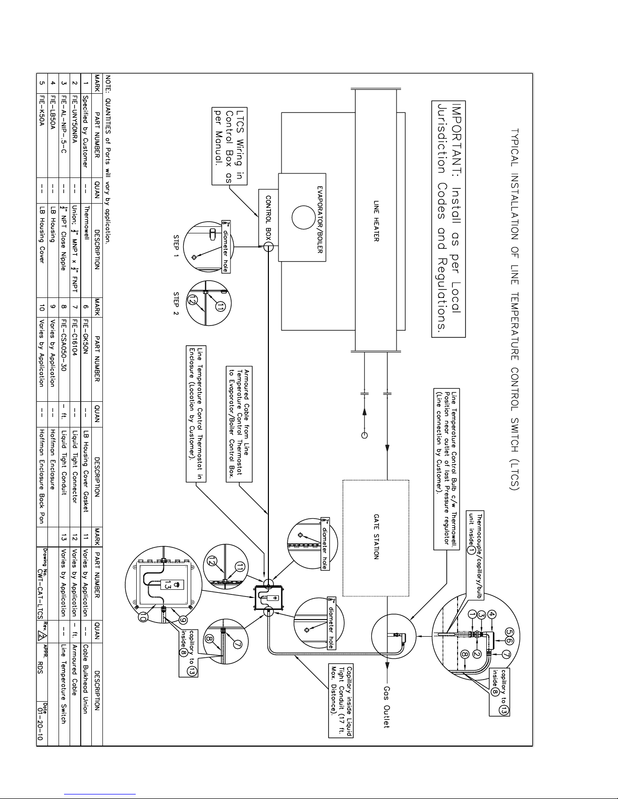
3.4 To install the line temperature control switch, refer to figure 3.1.2.
3.5 Place B-Vent exhaust stack on boiler (see section 4.1.22 for images of
the stack, and Appendixes D, E, and F at the back of the manual):
• Remove exhaust stack blind or cover. Be sure to save the cover/
blind gasket on the stack, as it is to be reused for the stack itself.
• Place rain cap on exhaust stack section (use screws),
• Place exhaust stack sections together if necessary (use screws),
• Place exhaust stack on boiler (lifting equipment maybe needed),
• Use bolts from cover to secure the boiler,
(boiler size 140 will not require bolts).
(Figure 3.5)
3.6 Pressure gauges to be placed in valves located on coil (See figure 3.6)
3.7 When completed all parts from crate should be used
Page 14
3.7.1 Note: Tecvalco highly recommends insulating gas piping from heater coil
outlet, up to the pipe where the downstream thermo-probe be installed.
3.7.2 Ready for pre-start up, start-up and run procedure (section 5)
Note: Please confirm all connections are tight and sealed.
PN :: HEA -BOI -MANUAL -016 | 20170316

COMPONENTS, SAFETIES, AND CONTROLS
3.8 Vent installation
Vent Installations shall be in accordance with “Venting of Equipment” of the
National Fuel Gas Code, ANSI Z223.1/NFPA 54, or “Venting Systems and Air
supply for Appliances” of the Natural Gas and Pro-pane Installation Code,
CAN/B 149.1, or applicable provisions of the local building codes.
Type of Vent: “B” Gas Vent. For stack assembly limitations, please look at
Appendix E to H.
a. Slide the vent stack assembly into the stack support bracket.
Lock stack in place.
b. Safely climb on a step ladder and place the stack support bracket
onto the stack flange located on top of the boiler as show on
page 81.
c. Use 1/2 inch Grade 5 bots and nuts provided to securely bolt the
vent stack.
4. Components, safeties, and controls
The CWT boiler is equipped with a number of safety systems that protect
personnel and equipment. These systems function automatically without the need
for constant supervision; however, some of the systems may require manual
start-up after a shut down. A thorough examination of the device should be
performed to determine the cause of any shut down. Activation of a safety shut
down may be a signal that maintenance is needed for the device. Contact
Tecvalco if the cause of the shut down is unknown.
The controls on the CWT operate on the energy provided by the thermopiles
located near the continuous pilot. The power provided passes through a circuit
that contains the various switches, as illustrated in the following pages.
In general, safety and control is quite simple; if any of the switches open, the
circuit will be broken and the main burner will shut down. If the low-low
water cut, or high-high pressure open both the main burner and the pilot will be
extinguished and a manual restart will be required (system purchased as of July
2014).
Note: Low-pressure boiler regulations may require testing or inspection of boilers and control systems. Please refer to all codes and regulations.
4.1 Boiler section
The firebox contains the burners, burner manifold, burner tray, Ignitor /thermopile assembly and the pilot and main fuel lines.
4.1.1 Swordfish burners (burner manifold or burner tray)
The burners are referred to as “swordfish burner”. Each burner is capable of a
maximum firing rate of 35,000 Btu/hr, at 14 inch w.c. and #45 orifices. They sit
in slots in the burner tray and can be equipped with a primary air adjuster (upon
customer request).
PN :: HEA -BOI -MANUAL -016 | 20170316
Page 15

COMPONENTS, SAFETIES, AND CONTROLS
The burner manifold is connected to the main fuel line and distributes the incoming fuel gas evenly to the burner.
Figure 4.1.1 -
The burner tray for 770,000 Btu’s, which contains
22 swordfish burners, one split manifold and
four thermocouples on two pilot assemblies.
Each swordfish burner generates 35,000 Btu’s per hour:
• 140,000 (Btu’s)= 4 swordfish burners
• 385,000 (Btu’s)= 11 swordfish burners
• 770,000 (Btu’s)= 22 swordfish burners
4.1.2 Pilot and thermopile assembly
The pilot and thermopile assembly consists of two 750 mV thermopiles, a pilot
burner, and a sparker.
Page 16
(Figure 4.1.2)
NOTE: The pilot orifice should be stamped with the part number BL22N.
PN :: HEA -BOI -MANUAL -016 | 20170316

COMPONENTS, SAFETIES, AND CONTROLS
4.1.3 The fintube assembly (primary heat exchanger)
The fintubes are located above the burners and span the width of the firebox.
The flue gas passes through the fins and exit through the flue and stack. As the
heated flue gas pass through the fintubes they heat the water-glycol mixture and
cause the water to boil, generating steam.
The photo above shows the primary heat exchanger with the side (saddle) tank
open. The heat transfer fluid sits in the saddle tanks and fins as the combustion
products pass upward, through the fins.
(Figure 4.1.3)
(Figure 4.1.3a)
NOTE: The internal design is different for different models.
PN :: HEA -BOI -MANUAL -016 | 20170316
Page 17
COMPONENTS, SAFETIES, AND CONTROLS
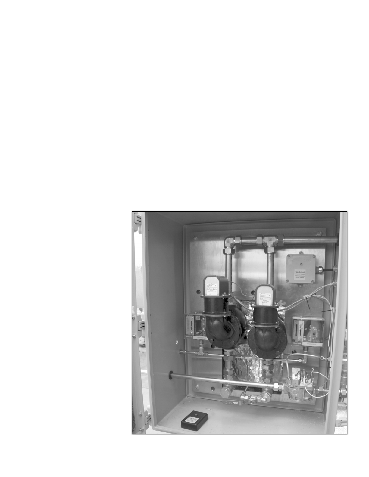
4.1.4 The control box
The control box is attached to the boiler and houses the various controls and
safeties for the CWT heating unit. The controls and safeties have been designed
to meet the requirements of ASME CSD-1. They include the Robertshaw gas
valve, the switches for operating steam pressure, high-high steam pressure (with
ESD), low-fluid level, low-low fluid level (with ESD).
Also included are the ignition box and a gauge to indicate main fuel line pressure downstream of the gas control valve. The gas line temperature control, while
usually remote from the boiler, is also connected to the control box and system
control logic.
Please refer to figures 4.1.4.a through 4.1.4.c
Page 18
(Figure 4.1.4a)
PN :: HEA -BOI -MANUAL -016 | 20170316

COMPONENTS, SAFETIES, AND CONTROLS
PN :: HEA -BOI -MANUAL -016 | 20170316
(Figure 4.1.4b) Wiring diagram for 770
Page 19

COMPONENTS, SAFETIES, AND CONTROLS
Page 20
(Figure 4.1.4c) - Wiring diagram for 385 and 140
PN :: HEA -BOI -MANUAL -016 | 20170316

4.1.5 P and ID drawings
COMPONENTS, SAFETIES, AND CONTROLS
PN :: HEA -BOI -MANUAL -016 | 20170316
(Figure 4.1.5a) - P&ID drawing for 770
Page 21

COMPONENTS, SAFETIES, AND CONTROLS
Page 22
(Figure 4.1.5b) - P&ID drawing for 770
PN :: HEA -BOI -MANUAL -016 | 20170316

COMPONENTS, SAFETIES, AND CONTROLS
PN :: HEA -BOI -MANUAL -016 | 20170316
(Figure 4.1.5c) - P&ID for 140 and 385
Page 23

COMPONENTS, SAFETIES, AND CONTROLS
4.1.6 Flame or flashback arrestors
It is a simple device, which quenches the flame from escaping to the outside of
the burner housing. Ensure you are following local codes and regulations in
the use and cleaning of a flame arrestor.
Page 24
(Figure 4.1.6)
PN :: HEA -BOI -MANUAL -016 | 20170316

COMPONENTS, SAFETIES, AND CONTROLS
4.1.7 Robertshaw gas valve
The Robertshaw gas valve is the primary fuel control on the boiler. The current
generated by the thermopiles in the continuous pilot powers the valve. The valve
has three settings: off, pilot, and on. When the valve is in the on position it will
respond to the controls in thermostats in the circuit and the unit will operate.
The pressure regulating process of the Robertshaw gas valves are bypassed.
The pressure regulating for the units is performed by the supplied Fisher HSR
regulators upstream of the Robertshaw gas valve.
WARNING: The Robertshaw gas valve is not intended for operation at higher
than 14.0” W.C. (.5 psi) supply gas pressure. Exposure to higher supply pressure
may cause damage and could result in fire.
Pilot tube connection
Gas valve top knob
Pilot adjustment (under cap)
NOTE: Please refer to Technical Manual section for detailed product information.
PN :: HEA -BOI -MANUAL -016 | 20170316
(Figure 4.1.7)
Page 25
COMPONENTS, SAFETIES, AND CONTROLS
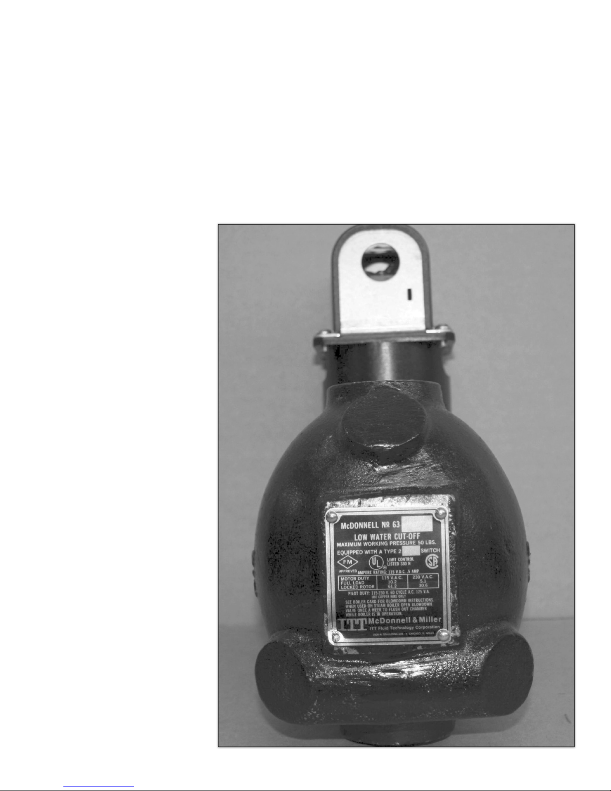
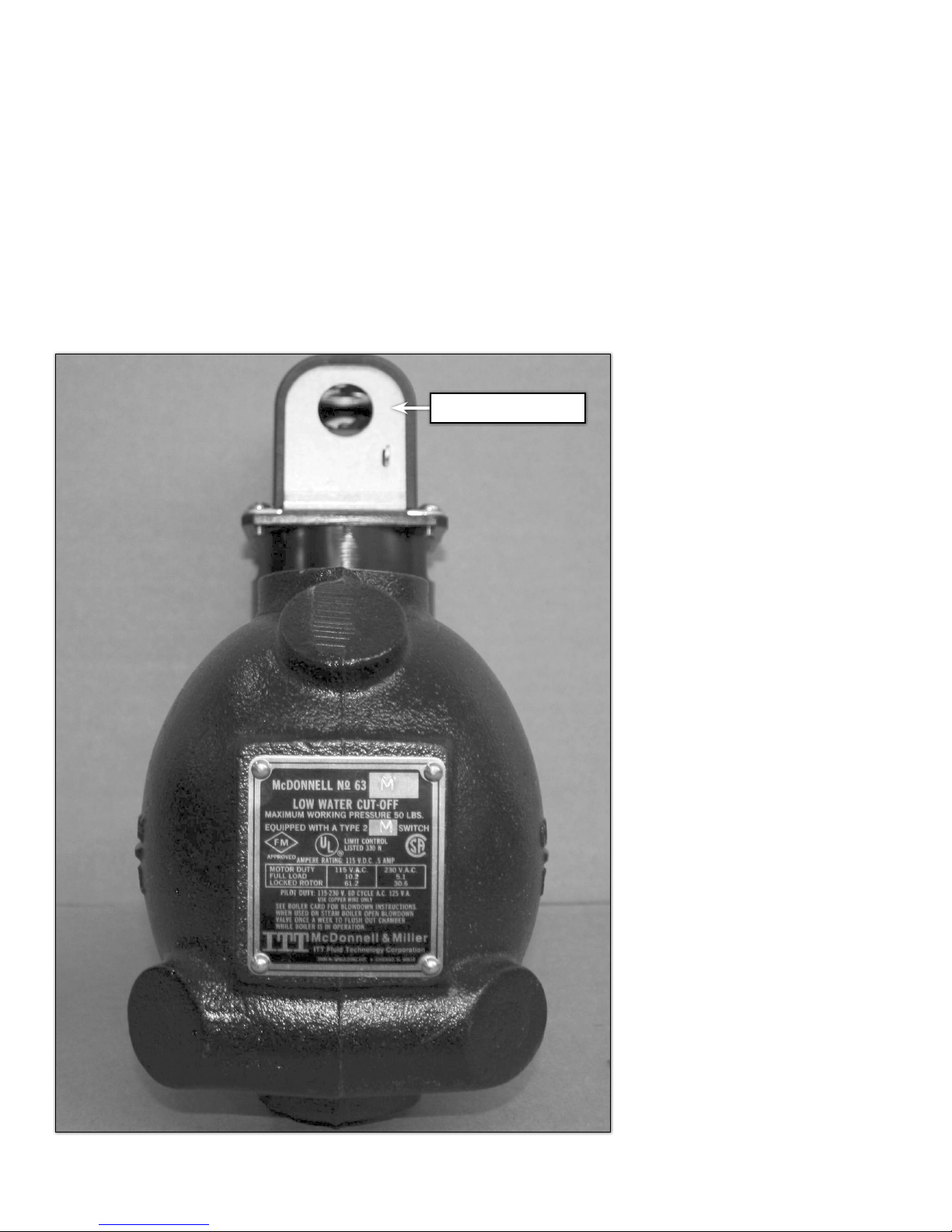
4.1.8 Low fluid level switch
If the fluid level in the heater falls below this level switch setting, the unit will open
circuits to the main burner gas supplies. The operator should review heater to
determine possible cause of fluid loss and repair and replace fluid. This will not
require manual relighting of the heater.
Page 26
(Figure 4.1.8)
PN :: HEA -BOI -MANUAL -016 | 20170316
COMPONENTS, SAFETIES, AND CONTROLS
4.1.9 Low-low fluid level switch with ESD
If the fluid level in the heater falls below this level switch setting, the unit will open
circuits to the pilot and main burner gas supplies shutting down both the pilot
and main gas. The operator must review heater to determine cause of fluid loss
and repair and replace fluid. This will require manual relighting of the heater.
Reset button
PN :: HEA -BOI -MANUAL -016 | 20170316
(Figure 4.1.9)
Page 27

COMPONENTS, SAFETIES, AND CONTROLS
4.1.10 Ignitor box and hand-held sparker
The ignition box assembly consists of a receiver in the control panel and a
separate hand-held sparker. Inside the sparker is an AA battery.
NOTE: Before lighting the evaporator, it is mandatory to test the atmosphere first
for combustible gases around the unit.
Receiver
Page 28
Hand held sparker
(Figure 4.1.10)
NOTE: When lighting the CWT unit using the hand held igniter this is the only time
that the system is capable of producing a spark to light gases and is not CL1 Zone
2 “Non-Incendive” certified. The atmosphere around the control cabinet should be
tested or checked prior to lighting the unit for personal safety.
PN :: HEA -BOI -MANUAL -016 | 20170316
COMPONENTS, SAFETIES, AND CONTROLS
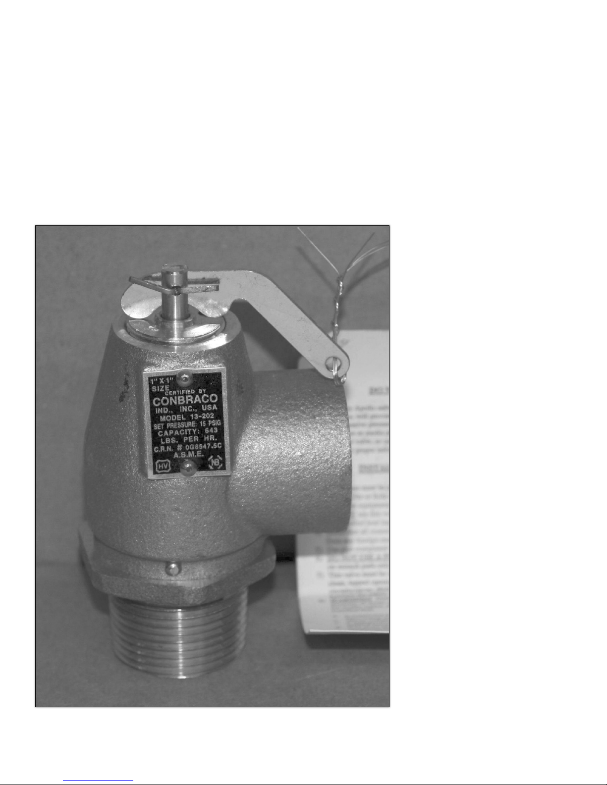
4.1.11 Pressure safety valve (relief valve)
The release of fluid from the heater may lead to decreased efficiency by
removing water that generates steam. If fluid is seen in the collection barrel
review the boiler for any issues and repair as needed. It may be necessary to
remove and replace fluid in the heater.
PN :: HEA -BOI -MANUAL -016 | 20170316
(Figure 4.1.11)
Page 29

COMPONENTS, SAFETIES, AND CONTROLS
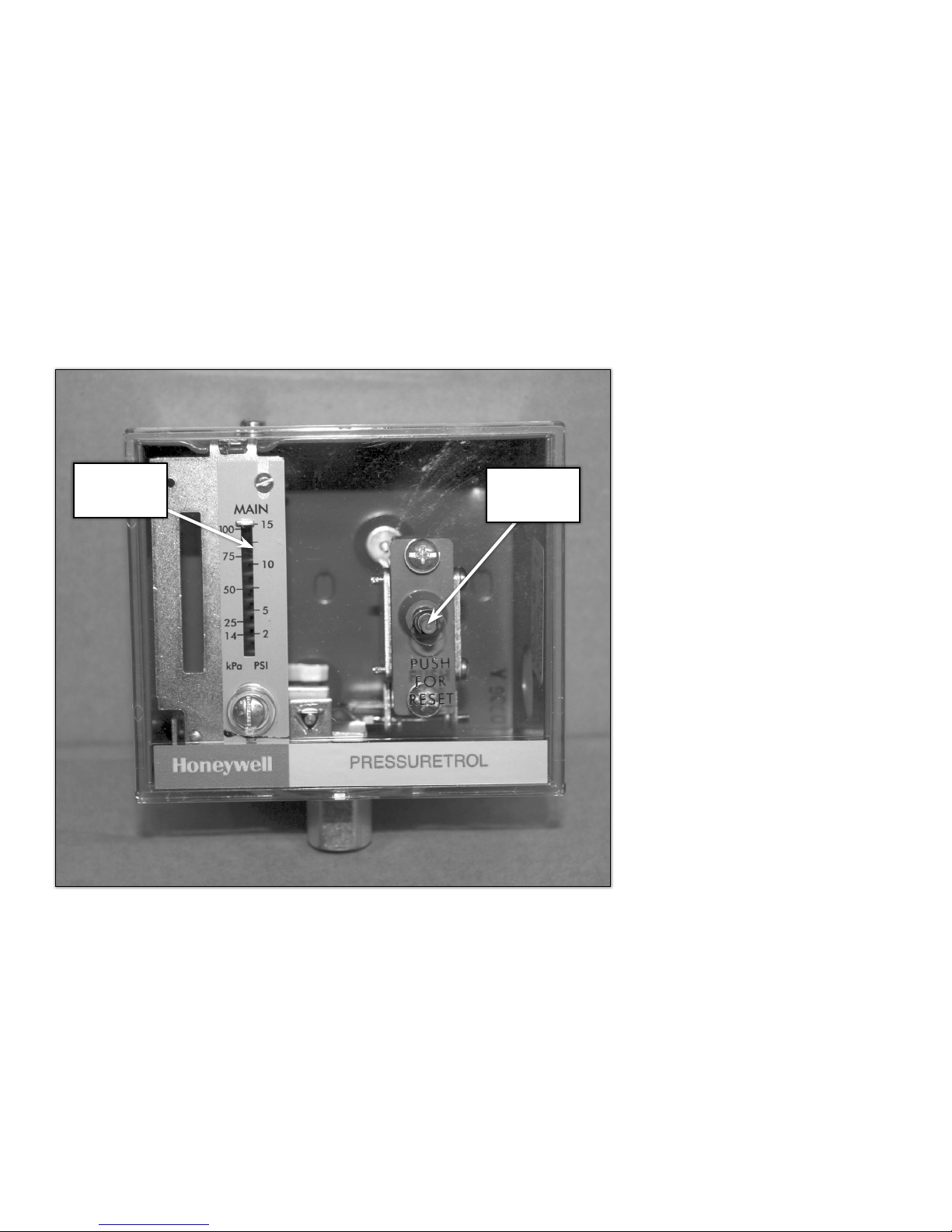
4.1.12 Operating steam pressure switch
If the steam pressure in the heater exceeds 5 psi, the unit will open circuits to the
main burner gas supplies, leaving the pilot burning. As the steam cools, decreasing
the pressure to below 5 psi the main burner will be allowed to relight automatically.
Differential
set at 2 psi
Main set
at 5 psi
Terminals
used
(Figure 4.1.12)
Page 30
PN :: HEA -BOI -MANUAL -016 | 20170316
COMPONENTS, SAFETIES, AND CONTROLS
4.1.13 High-high steam pressure switch with ESD
If the steam pressure in the heater exceeds 10 psi, the unit will open circuits to
the pilot and main burner gas supplies causing both the main flame and pilot to
extinguish. The operator must review heater to determine the cause of the excess
pressure. A manual resetting of the ESD switch will be required prior to relighting
heater.
Main set at
10 psi
ESD reset
button
(Figure 4.1.13)
PN :: HEA -BOI -MANUAL -016 | 20170316
Page 31

COMPONENTS, SAFETIES, AND CONTROLS
4.1.14 Temperature control (line temperature control)
The line temperature control monitors the temperature of the gas in the
downstream gas piping.
It is generally set between 0°C (32°F) and 5°C (41°F) in natural gas distribution
applications. If the gas temperature in the downstream gas piping falls below this
set point the switch will close, allowing gas to flow to the main burner, generating
steam for heat transfer.
Once the heated gas passing the line temp controller has exceeded its set point.
The contacts will open which stops the gas flowing to the main burners.
If low or zero gas flow situations exist we strongly recommend installing an
additional probe called the High Temp Shut Down (HTSD) near the outlet of the
high-pressure coil.
The temperature set point on the HTSD probe must then be increased to account
for the pressure drop through the gate station.
(As a general rule, a 100 Psi / 689.4 kPa drop in pressure will result in drop of
7°F (-13.9°C) of temperature).
NOTE: Please refer to technical manual section for detailed product information.
Page 32
PN :: HEA -BOI -MANUAL -016 | 20170316

COMPONENTS, SAFETIES, AND CONTROLS
4.1.14a 140 / 385 boiler line temperature controller (T675A switch)
As the temperature of the controlled medium falls below the set point less
differential, the T675A switch makes terminals R to B an energize a normally
closed solenoid valve to provide heat. Figure 4.1.14a.1 shows the operation of
the T675A. Figure 4.1.14a.2 shows the location of the adjustment dial on models
with an adjustable differential.
R
B
(Figure 4.1.14a.3)
(Fi gur e 4.1.14a.1)
(Figure 4.1.14a.2)
PN :: HEA -BOI -MANUAL -016 | 20170316
Page 33

COMPONENTS, SAFETIES, AND CONTROLS
4.1.14b 770 boiler line temperature controller (T678A switch)
When the temperature at the sensing element rises above the set point of the
controller, the switch on the right breaks R to W. Should the temperature continue
to rise through the preselected interstage differential of the contorller, the switch
on the left will make R to W.
Conversely, on a temperature fall, the switch on the left makes R to B, providing
first step switching. If the temperature continues to fall, the switch on the right
makes R to B to provide sequencing of equipment.
The T678A temperature controller has an adjustable interstage differential. The
set point adjustment knob determines the temperature at which the right switch
operates. The left switch can be adjusted to perate from 3 to 10 degrees F (1.7 to
5.6 degrees C) (or 3.6 to 12 degrees F (2.0 to 6.7 degrees C) on some models)
above the point of operation of the right switch. An illustration depicting the
operation of the T678A is shown in figure 4.1.14b.1. The interstage differential
is adjusted by turning the star wheel with a narrow screwdriver instered into the
rectangular hole in the chasis (figure 4.1.14b.2).
(Fi gur e 4.1.14b.1)
(Figure 4.1.14b.2)
Page 34
2 1
B
R
PN :: HEA -BOI -MANUAL -016 | 20170316
B
R
(Figure 4.1.14b.3)

COMPONENTS, SAFETIES, AND CONTROLS
4.1.15 Fisher HSR regulator
Pressure to the Robershaw gas control valve. The maximum inlet pressure to the
HSR is 20 psi due to the .5” orifice installed within the unit. Vent as per local
codes.
The following table is using a HSR with .5 inch orifice.
Inlet pressures and standard cubic feet per hour for each boiler assembly:
BOILER SIZE INLET PRESSURE REQUIRED SCFH
140 1 psig 200
315 3 psig 340
385 5 psig 480
630 5 psig 680
770 (Single) 5 psig 1050
770 (2-385) 5 psig 960
1155 (3-385) 5 psig 1440
1.54 (2-770) 5 psig 2100
2.3 (3-770) 5 psig 3150
3.1 (4-770) 5 psig 4200
4.6 (6-770) 5 psig 6300
PN :: HEA -BOI -MANUAL -016 | 20170316
(Figure 4.1.15)
(Table 4.1.15)
Page 35

COMPONENTS, SAFETIES, AND CONTROLS
4.1.16 Fuel pressure gauge IWC (inches of water column)
(Figure 4.1.16)
Pressure measurements in inches of water column
1 psi = 27.68 inches of water column, so 0.45 psi would be
27.68 * 0.45 = 8.3 inches of water column
WARNING: The Robertshaw gas valve is not intended for operation at higher
than 14.0” W.C. (.5 psi) supply gas pressure. Exposure to higher supply pressure
may cause damage and could result in fire.
4.1.17 Emerson 289L relief valve
This valve is set to relieve excess gas measurement at 14 inches water column.
Vent as per local codes.
Page 36
(Figure 4.1.17)
PN :: HEA -BOI -MANUAL -016 | 20170316

4.1.18 Fuel train drawings
COMPONENTS, SAFETIES, AND CONTROLS
Fuel gas assembly
drawings can be
found in Appendix J.
PN :: HEA -BOI -MANUAL -016 | 20170316
P&ID Drawing for 140 and 385 (Figure 4.1.18a)
Page 37

COMPONENTS, SAFETIES, AND CONTROLS
Page 38
P&ID Drawing for 770 (Figure 4.1.18b)
PN :: HEA -BOI -MANUAL -016 | 20170316

4.1.19 Pressure vacuum gauge
COMPONENTS, SAFETIES, AND CONTROLS
The vacuum gauge indicates the strength of vacuum. When the unit has a steam
temperature of less that 140 degrees Fahrenheit, the gauge should be in the
range of –20 to –25 inches HG.
Note: Heat transfer efficiency will increase with high vacuum.
PN :: HEA -BOI -MANUAL -016 | 20170316
(Figure 4.1.19)
Page 39

COMPONENTS, SAFETIES, AND CONTROLS
4.1.20 High pressure coil gauge
Page 40
(Figure 4.1.20)
Picture of pressure gauge above is the standard pressure gauge CWT uses on
inlet and outlet of high pressure coils to determine the gas pressure.
PN :: HEA -BOI -MANUAL -016 | 20170316
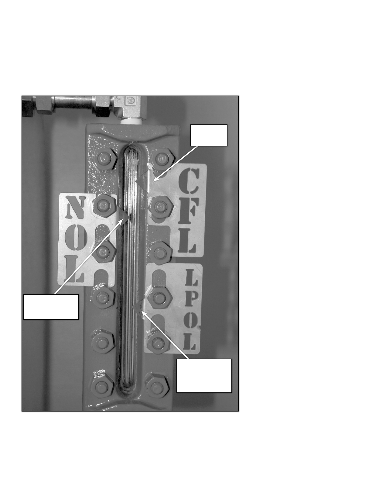
4.1.21 Liquid level gauge
COMPONENTS, SAFETIES, AND CONTROLS
Cold Fluid
Level
Normal Operat-
ing Level
Pictured above is the liquid level gauge, which indicates the availability of the
heat transfer fluid in the system.
PN :: HEA -BOI -MANUAL -016 | 20170316
Lowest
Permissible
Operating Level
(Figure 4.1.21)
Page 41

COMPONENTS, SAFETIES, AND CONTROLS
4.1.22 Exhaust vent
The exhaust stack cap supplied with the CWT heater is a residential, B-Vent sytle
stack cap. They come in six (6) inch, eight (8) inch, or twelve (12) inch, depending
on the boiler model.
The six inch stack has a high-wind stack cap with bird screen, while the eight (8)
and twelve (12) inch stacks are both equipped with the bird screen.
Stacks are to be cleaned out (blown out) periodically as part of the routine
maintenance. B-vent stacks are double-walled galvalume and can dent very easily.
Proper care when installing the vent stack should be taken to prevent damage.
Refer to Appendix D, E, and F for assembly details.
6” B-vent for 140,000
BTU boiler
Page 42
8” B-vent for 315,000 or
385,000 BTU boiler
12” B-vent for 770,00 BTU
boiler
PN :: HEA -BOI -MANUAL -016 | 20170316
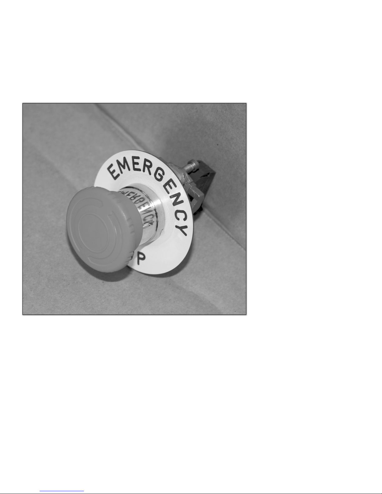
4.1.23 Emergency shutdown device
COMPONENTS, SAFETIES, AND CONTROLS
Pushing the emergency shutdown button will open contact, removing power from
the control system. This will extinguish the main flame as well as the pilot.
To reset, turn the mushroom button clockwise. After this, a manual reignition will
be required.
PN :: HEA -BOI -MANUAL -016 | 20170316
(Figure 4.1.23)
Page 43

COMPONENTS, SAFETIES, AND CONTROLS
4.2 Condenser section (heat exchanger)
The condenser or heat exchanger is the part of the CWT Boiler where the steam
condenses on the pressure coil that contains the cold gas. When the steam contacts the cold pipe it releases latent heat by condensing to water. The water
falls back to the boiler section by gravity. The energy released as the steam
condenses to water is significant. Just as it takes a significant amount of energy
to convert water to steam, a large amount of energy is released when the steam
condenses back to water. The inlet and outlet of the high-pressure piping is
not defined, either flow direction will result in an acceptable heat exchange.
Gas outlet
Gas inlet
(Figure 4.2)
Page 44
PN :: HEA -BOI -MANUAL -016 | 20170316

COMPONENTS, SAFETIES, AND CONTROLS
4.2 .1 The heat exchanger can
The condenser/heat exchanger can contains the pressure coil and provides the
vessel in which the steam is allowed to condense on the coil.
Inside the condenser can (photo below) the receivers at the far end support the coil.
Inspection port
Receivers to support the coil
Steam inlet
Condensate (water) outlet
PN :: HEA -BOI -MANUAL -016 | 20170316
(Figure 4.2.1)
Page 45

COMPONENTS, SAFETIES, AND CONTROLS
4.2.2 High-pressure process coil
The high-pressure coil is the device that contains the gas to be heated. It is a
registered pressure device built and certified in accordance with ASME B31.3
(pressure piping). The coil is typically a serpentine device as pictured below,
the cylindrical coils are helical spiral coils and adjacent to it are standard
high-pressure coils.
(Figure 4.2.2a)
Page 46
PN :: HEA -BOI -MANUAL -016 | 20170316

COMPONENTS, SAFETIES, AND CONTROLS
Support
These provide support and grounding for the coil inside the can
PN :: HEA -BOI -MANUAL -016 | 20170316
(Figure 4.2.2b) Note the nubs on the end of the coil.
and are not part of the pressure envelope.
Page 47
START-UP PROCEDURE
5. Start-up procedure
On start up in very cold weather the boiler coil might be quite cold. Ensure the unit is warmed up to higher than 0°C (32ºF) prior
to pressuring up the coil. If the boiler is down in very cold weather and there is no gas flow passing through the unit, the boiler
should be isolated and the pressure reduced.
WARNING: Test atmosphere around the boiler prior to lighting (procedure also on control box door). If an explosive mixture
exists locate and shut off the source of the fuel and ensure the flame arrestor is in place and secure.
1. Open main gas ball valve on the fuel gas supply.
2. Turn Robertshaw control valve to the “PILOT” position.
3. Depress pilot button.
4. Insert hand held ignitor into the ignition box in the control cabinet and depress the button, while still depressing the pilot
button. This causes a spark to jump across the pilot assembly. You should hear the sparking. Once the pilot lights you will
no longer hear the spark. It may take several minutes for the natural gas to reach pilot area, due to the length of fuel gas
supply line and the amount of trapped air.
5. Hold pilot button down for 45 seconds or more and then release.
6. Look through the site glass to confirm the pilot remained lit. If not, check that the valves on the fuel supply are open and
return to step four. If this problem persists press the reset on the ESD control and try again or check fuel gas
7. With established pilot turn Robertshaw control to the “ON” position.
8. Change the setting of the line temperature switch to force heater to light. The main gas control valve should open and the
heater should light. On first light you may get a slight burst of gas because of air in line. Turn to pilot for a second and then
back to on. If the
main burner does
not light, confirm
that all the dial type
switches are calling
for heat.
9. Once the boiler is
operating, examine
the flame and note
any instability.
10. Use the CWT Line
Heater checklist
inspection form
(section 7.16) to
record the initial
data.
11. For 385,000 and
770,000 Btu/hr:
Allow 5 minute
complete shutoff
before attempting
to re-fire.
Page 48
PN :: HEA -BOI -MANUAL -016 | 20170316

6. Typical operation
During the first operating cycle of the boiler, allow the system to run. Monitor
the pressure, the discharge temperature and the level of heat transfer fluid in the
sight glass. During initial start up and during normal operation the level of heat
fluid will vary widely in the sight glass.
While the system is warming up, you will hear clattering and clanking inside the
evaporator, which is normal and due mainly to steam being produced in the fin
tubes along the tube wall and partially to thermal expansion of steel inside the
system. Once the boiler is warm (the main flame bed turns on and off to keep
the gas warm) note the duration of the on and off cycles and the maximum and
minimum temperatures reached. The season and gas flow will determine the
cycle times; slow flow means long cycles and high flow mean short cycles. Use
the attached Inspection sheet (section 7.16) to record start-up data. If the boiler
appears not to be warming gas sufficiently consider increasing the fuel pressure
at the Fisher HSR. Insufficient fuel gas will cause the unit to run constantly, and
will not heat properly. If the heater cycles off and on it has
sufficient energy to heat the gas.
TYPICAL OPERATION
To achieve low flow rate setting, while burner is in operation, turn the knob
on the Robertshaw gas valve to reduce the input. The minimum and maximum
allowable inlet pressures are indicated on the rating plate inside the control
panel.
6.1 Glycol
The glycol used in the CWT heater is a Dow Frost HD 50/50 pre blend. Our Heat
Driven Loop technology does not use the glycol as the heat transfer medium.
Glycol in the CW T system is only for freeze protection. Customers are advised
that when sending glycol reports for lab tests that the following results may be
identified:
1. Low to no corrosion inhibitors present: this condition is typical for
CWT units as through the process of separation that the glycol
undergoes, the inhibitors actually drop out and/or burn up.
2. High solids content: The presence of some residuals of the
manufacturing process are typical, as we are not able to remove
them all from the system. There are no pumps or moving parts that
will be affected by small or trace amounts of residuals. However, if
large amounts are found, refer to the maintenance section of this
manual.
3. Discoloration of the glycol in CWT systems is typical and the amount
will vary from site to site depending on the station loading. Do not be
alarmed. Confirm the freeze protection is still lower than the lowest
ambient condition for the location of the heater.
PN :: HEA -BOI -MANUAL -016 | 20170316
Page 49

TYPICAL OPERATION
Dow has a series of standard computer generated responses for every
sample they check, the baseline for the responses is “New” DowFrost
HD. Here are some examples and factory responses to each:
“This fluid has cloudy appearance and suspended solids”: Typically the solids
present are inherent to the manufacturing process at the factory level and should
only become a concern if the iron level increases over future annual samplings.
“The pH is above the maximum recommended level for Dow fluids”: There is
only a concern if the pH level exceeds 12 and the pH level of the glycol should
decline over time.
“Solids can be detrimental to pump seals”: Our technology features no moving
parts such as pumps and circulators.
“Azole based copper inhibitor is low. Insufficient copper or copper alloy corrosion protection”: The CWT heater operates in a vacuum and inherent corro-
sion protection is achieved by the lack of oxygen in our system and there are no
copper or copper alloy components int he CW T systems.
“High amounts of solids will significantly reduce the heat transfer properties
of this fluid”: Unlike conventional water bath heater technology the glycol found
in our heater is not used for heat transfer.
“Concentration and freeze point comments”: As provided the 50/50 blend of
glycol and water provides freeze protection to approximately –30 degrees Fahrenheit and the user should ensure this number stays below the minimal ambient
temperature of the site.
6.2 Control settings
CONTROL SETTINGS
Operating steam pressure switch Factory setting - 5 psi
High-high steam pressure switch with ESD Factory setting - 10 psi
Low fluid level switch Factory setting
Low-low fluid level switch with ESD Factory setting
Pressure safety valve (relief valve) Factory setting - 15 psi
Line temperature 0°C/32°F to 5°C / 41°F
Depending on the conditions and the
nature of the gas set this as required
(About 2°C/ 35°F).
Page 50
Gas bundle outlet temperature 24°C / 75°F to 43°C / 110°F
(HTSD) Depending on the season.
(Table 6.1)
PN :: HEA -BOI -MANUAL -016 | 20170316

Note: When multi-heating boilers are used on a heat exchanger, the line
temperature switches should be rotated, so that the single boiler is not always the
lead unit.
6.3 Tuning the CWT Boiler
The CWT Boiler has a significant advantage over conventional systems
in that it has a high turndown capability. A CWT boiler can run with fuel inlet pressures varying between 3.5” WC (0.13 psi) and 14” WC (0.52 psi). This allows the
operator to set the cycle time of the boiler to best fit the load. Ideally, a perfectly
tuned heater would run 100 per cent of the time on the coldest day of the year. In
practice, a well-tuned boiler will typically cycle three to four times per hour.
Cycle time is determined by firing rate and load. The “on”, or firing, portion of the
cycle can be controlled by the firing rate. If the firing rate is increased this will
shorten the on part of the cycle. Flow and pressure drop through the station
controls the “off” part of the cycle.
Some general rules for tuning include:
TYPICAL OPERATION
• If possible, set the firing rate during high station load conditions and
let the boiler stabilize (warm up) before continuing.
• Fire at a high enough rate that the boiler will cycle at least
three times per hour.
• Fire at a high enough rate to ensure the stack temperature exceeds
130°C (266º F). Below this point incomplete combustion may occur
and “raining” may occur in the stack.
• Fire at a low enough rate that the stack temperature does not exceed
250°C (482º F). Above this would impair the boiler or stack.
• Obtain a combustion analysis and optimize the combustion.
Observe the flame and address any lifting and/or hunting. Consult Tecvalco for
advice.
6.4 Cycles
The CWT Boiler normally operates with cycles on and off (figure 6.3a). The
nature of the cycle depends on the firing rate and load as well as the set points on
the controls primarily the gas temperature control. (See section 6.1)
When the boiler fires in response to a call for heat by the gas temperature control
the boiler begin the process of boiling the water. As the steam temperature
and pressure increase more heat is delivered to the process gas. Eventually the
temperature of the gas reaches the set point of the gas temperature control and
the main burner shuts down. Upon shutdown, a large amount of energy remains in
the boiler and the temperature of the gas will continue to climb for some time
(depending on the load). As a result the heater tends to overshoot the set point
by a few degrees. Similarly when the heater is off, and the temperature is falling,
when the gas line temperature control reaches the set point (plus the dead-band) it
will call for heat and the boiler will fire. It might undershoot the set point before the
boiler catches up.
PN :: HEA -BOI -MANUAL -016 | 20170316
Page 51

TYPICAL OPERATION
G as Tem p (H eat er Off) Ga s Te m p (He ate r F iring)
Heater Off
Heater Firing
1
2
3
5
6
8
Gas Temperature Profile with CWT Line Heater (Illustrative Purposes Only)
1 0 .0
8 . 0
7
6 . 0
4 . 0
2 . 0
Gas Temperature (°C)
0 . 0
-2 .0
4
-4 .0
-6 .0
0 1 2 3 4 5 6 7 8 9 1 0 11 12 13 14 1 5 1 6 17 1 8 1 9 2 0 2 1 22 2 3 2 4 2 5 2 6 27 2 8
Page 52
(Approx. 8min)
(Approx. 5min)
Time
(Figure 6.3a)
PN :: HEA -BOI -MANUAL -016 | 20170316

7. Maintenance
WARNING: Never perform maintenance on the boiler when under
operation or hot. Please ensure that the unit is shut and cooled down for
a minimum of 25 minutes, and that all fuel gas to the device has been shut off prior
to performing any maintenance operation.
MAINTENANCE
ALWAYS assume that there is pressure in the system.
7.1 Maintenance schedule
It is suggested that the boiler should undergo a complete inspection, maintenance
and cleaning at least semi-annually (spring and fall). Use the following maintenance
checklist in conjunction with the CWT inspection sheet (section 7.16). The inspection
can be done in connection with maintenance and can begin with a boiler that is operating; however sufficient time should be available to allow the boiler to cool prior
to the maintenance activities.
Service inspections
a. A poor adjusted or malfunctioning appliance can deposit soot and other
debris which can enter the vent system. The vent should be visually inspected at
least annually for the presence of deposits of soot or debris. Blow air through the
stack till no debris.
b. The boiler must be periodically inspected by a qualified serviceman or
Tecvalco service technicians.
Inspection Checklist
qTake pictures of the complete heater.
qRecord heater serial number and coil serial number.
qShut heater off and allow it to completely down.
qEnsure vacuum is between -20 inches and -26 inches.
qCheck the glycol level in the sight glass.
qOpen the burner box door and take pictures of burner tray and burner box.
qRemove stack and take pictures of stack walls and top of fin tubes.
qRemove burner tray gas line and disconnect pilot line from tray. Loosen off
main pilot line nut. Burner tay may be difficult to remove as side walls can
distort, slightly pinching the tray in place.
qWhen burner tray is removed take pictures of bottom of fin tubes. If possible,
do a visual inspection.
qUse an air compressor to blow off top and bottom of fin tubes.
qOnce complete, do a visual inspection. If not clean, then repeat.
qUse a vacuum cleaner to clean up the bottom of burner box and, if possible,
the top of the fin tubes.
qTake pictures of cleaned-out burner box and top of fin tubes.
qClean burners from tray with air and check orifices to see if they are clean.
This may require disassembly.
qClean flame arrestor cell with air or soapy water solution. Flame arrestor
should be clean and free of debris.
qReassemble burner tray and install back in burner box. Hook up gas line and
pilot assembly.
qCheck wires in burner box for defects. If necessary, replace.
qClose up burner box area.
qIf heater has cooled down enough, take glycol samples.
qWhen complete, relight heater using start-up procedure.
WARNING:
Inspections and tests
included in this section may be
regulated by local, Federal, or
other jurisdictions. Please
review all applicable codes
and regulations prior to
conducting any activities on
CWT equipment.
WARNING:
Performing pressure tests on
the system can be hazardous,
and should only be performed
by trained professionals.
Contact Tecvalco if you have
any questions.
WARNING:
Keep boiler area clear and free
from combustible materials,
gasoline and other flammable
vapors and liquids
PN :: HEA -BOI -MANUAL -016 | 20170316
Page 53

MAINTENANCE
WARNING:
Inspections and tests
included in this section may be
regulated by local, Federal, or
other jurisdictions. Please
review all applicable codes
and regulations prior to
conducting any activities on
CWT equipment.
Flame arrestor gasket
qOnce inspection is comlete, test controls using a dry block where required, or
a multimeter and pressure station set-up for pressure switches:
qOperating steam pressure switch (5 psi)
qHigh-high steam pressure switch with ESD (10 psi). Will require relight.
qLine temperature control switch. Set to desired temperature.
qLow water cut-off. Will require relight.
qLow-low water cut-off with ESD. Will require relight.
qEmergency push button. Will require relight.
Once the heater is up and running, complete the final checks as follows:
qCheck millivolt readings.
qCheck temperature of gas at station outlet, as well as in and out of the coil
SEMI-ANNUAL SEMI-ANNUAL
qCheck fuel pressure, in inches WC.
qCheck steam and stack temperature.
qPerform combustion analysis, if possible.
WARNING: Do not obstruct the flow of combustion and ventilation air.
7.2 Cleaning the flame arrestor
The flame arrestor on the boiler should be inspected and cleaned at least
annually in order to ensure that it is in good working order and that enough air
is provided to support proper combustion. In some cases more frequent cleaning
may be required.
a. Ensure the boiler is off prior to removing the flame arrestor.
b. Remove the flame arrestor and examine the cell – ensure that it is
not damaged. Examine the gasket around the flange and ensure it
is intact and in good condition.
c. Using compressed air or nitrogen blow out any dust or
contaminants that might be in the weave of the cell.
d. While the flame arrestor is removed inspect the burners – look
specifically for signs of scale and or soot.
e. Replace the flame arrestor; ensure that the cell fits tightly against
the back flange.
7.3 Swordfish burner clean-up
WARNING:
Performing pressure tests on
the system can be hazardous,
and should only be performed
by trained professionals.
Contact Tecvalco if you have
any questions.
Page 54
Assembly drawings of the burner trays can be found in Appendix G, H, and I.
1. Turn gas valve to pilot, then turn off main gas. Let cool for at least
.5 hours.
2. Open heater door and disconnect main gas flex from burner
manifold. Unhook pilot gas line at Hylok fitting and remove
burners if possible. Disconnect pilot bracket from burner tray.
This will allow operator to remove the burner tray without having to
disconnect the wires.
3. Remove burners from unit
4. Check the burner venturi ports are free of foreign particles (dust,
lint and debris)
5. Clean burners with bristle brush and/or vacuum cleaner. DO NOT
alter burner ports or pilot location
PN :: HEA -BOI -MANUAL -016 | 20170316

MAINTENANCE
6. If the fin tubes need to be inspected and cleaned move on to
section 7.4 before reinstalling the burner.
7. Otherwise, reinstall burners in unit. Make sure front and rear of
burners are installed correctly in burner support brackets
7.4 Inspecting and cleaning the fin tubes
The fin tubes should be inspected and cleaned semi-annually. It is suggested that
this be done before and after peak times (spring and fall, possibly).
1. Perform steps 1 to 3 of swordfish burner clean-up (7.3).
3. The stack will need to be turned to the side or removed
for inspection and cleaning of the top of the fin tubes.
4. Once the burner tray and stack have been removed, take pictures
of the fine tubes above and below, if possible. Note any problem
areas and contact Tecvalco.
5. Use an air compressor or compressed air to blow out the fin tubes
from the top down and then from the bottom up. Clean up any
particles from bottom of the heater and any scale still on the top of
the fin tubes. If needed, use a mirror to help in the inspection.
6. When cleaning is complete take pictures to note improvements.
7. Replace the stack and burner tray.
SEMI-ANNUAL
WARNING:
Inspections and tests
included in this section may be
regulated by local, Federal, or
other jurisdictions. Please
review all applicable codes
and regulations prior to
conducting any activities on
CWT equipment.
WARNING:
Performing pressure tests on
the system can be hazardous,
and should only be performed
by trained professionals.
Contact Tecvalco if you have
any questions.
PN :: HEA -BOI -MANUAL -016 | 20170316
Page 55

MAINTENANCE
Top valve
SEMI-ANNUAL
7.5 Glycol sample procedure
Most CWT heaters are equipped with a double valve system, which will allow you
to take a glycol sample without losing an appreciable amount of vacuum.
The procedure is as follows:
1. Take the sample when the heater is cold, in summer if possible.
During operation the water and glycol separate and a sample will
have an unrepresentatively high amount of glycol.
2. Open the top valve and wait a minute or two.
3. Close the top valve and open the bottom to obtain the sample,
close the bottom valve
4. Repeat steps 2 and 3 three or four times. Such process would
purge and remove the fluid standing in the low spot and to get a
sample.
5. Open the top valve.
6. Open the bottom valve for 3 seconds only. This allows the system
to pour back and bring fluid into the sample leg. Close both valves.
7. Repeat steps 2 and 3 and obtain the required sample.
8. Note the vacuum pressure when complete.
9. For older Series II 140s with a temperature probe in the
sample port, sample times will be much greater.
10. NOTE: Glycol samples are acceptable if they meet the minimum
ambient temperature of the site location.
Bottom valve
Page 56
NOTE:
All CWT heaters are flushed and cleaned at the factory prior to shipping to site.
Despite standard cleaning processes, it is possible that some residuals from
manufacturing may remain in the system. The amount of these residuals can
vary, and it is recommended that the system be inspected after the first season
of peak volume service. If the levels of residuals found during inspection are high
and there are visible high amounts of contaminants, there is a chance that the
float controls and pressure controls can be affected. In this situation, a boiler
flush may be required to remove the majority of the contaminants.
You may also notice some glycol discoloration after the first peak season. This is
typical for CWT heaters and the amount of discoloration will vary from site to site
depending on station flow/loading and the amount of residuals remaining from
the manufacturing process. This discoloration does not indicate that the primary
function of the glycol (freeze protection) has be compromised. CWT heaters do
not rely on the glycol for heat transfer.
(Figure 7.5)
PN :: HEA -BOI -MANUAL -016 | 20170316

MAINTENANCE
7.6 Testing the powerpiles
Test the powerpile assembly using the following procedure:
NOTE: Use a voltmeter set at 1000 mV
(Figure 7.6)
Test 1 – Complete system
Connect to terminals 2 and 3. Ensure the thermostats are calling for heat (turn
them up). Power should be >100 mV. The main burner should fire. If the voltage
>100 mV but the valve does not open replace the valve. If the power is <100 mV
proceed to test 2.
Test 2 – Thermopile output
Connect to terminals 1 and 2. The thermostats should not be calling for heat
(turn them down). The main burner is off the voltage should be > 325 mV. If it is
less replace the thermopiles.
SEMI-ANNUAL
NOTE: If through age or failure the
thermopiles can no longer generate
the power to operate the gas valve
they can be replaced quite simply. In
this case all the thermostats, controls
and safeties would shut down.
WARNING:
Inspections and tests
included in this section may be
regulated by local, Federal, or
other jurisdictions. Please
review all applicable codes
and regulations prior to
conducting any activities on
CWT equipment.
Test 3 – Pilot dropout
Connect to terminals 1 and 2. Hold the pilot until the power level stabilizes. Shut
the pilot off and note at which point the magnet drops (should be between 120
and 30 mV (falling). If the dropout does not occur or occurs outside these points
replace the gas valve.
PN :: HEA -BOI -MANUAL -016 | 20170316
WARNING:
Performing pressure tests on
the system can be hazardous,
and should only be performed
by trained professionals.
Contact Tecvalco if you have
any questions.
Page 57
MAINTENANCE
TEST
OPENING
CUT OFF
LEVEL
SEMI-ANNUAL
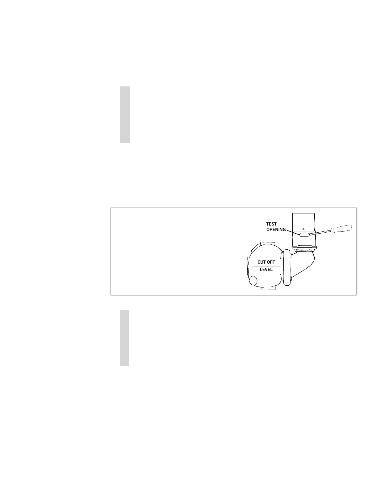
7.7 Test procedure for boiler controls
Testing of low fluid level switch and low-low fluid level switch with ESD
1. This test can be performed with the heater on.
2. When boiler is running, gently insert a screwdriver or similar tool in
the test opening below the switch.
3. Lift the linkage to cause the float to drop, thereby simulating a low
water condition.
4. This will kill the pilot and a relight will be required.
5. This test will need to be performed on both low water cut-offs.
6. The low-low water cut-off has a reset on it and will need to be
pushed after it
has been tested.
7. Relight will be required.
Control can be tested on a hot water boiler
by gently inserting a screwdriver or similar
tool in the test opening below the switch (see
illustration at right) and lifting linkage to
cause float to drop, thereby simulating a low
water condition.
SEMI-ANNUAL
7.8 Testing the emergency shut-down button
1. This is a simple procedure. As the boiler is running, push the button.
This will kill all switches and the gas. The boiler will need to be relit.
Page 58
PN :: HEA -BOI -MANUAL -016 | 20170316
MAINTENANCE
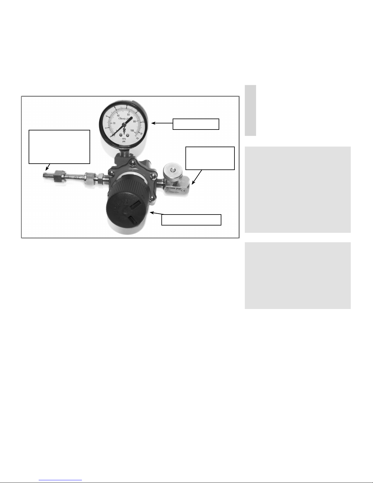
7.9 Pressure switch tests
Pressure gauge
3/8” tubing connection
to hook-up to the cap
end on the vacuum/
pressure gauge on the
outside of the control box
Regulator to set pressure
End to hook-up air
hose (connection
supplied by others)
(Figure 7.9)
The above photograph illustrates what the boiler pressure switch regulator tool
looks like. This tool is required to test the pressure switches on the boiler.
Using the tool to perform tests on pressure switches
1. The boiler will need to be turned off.
2. Let the boiler cool down for a minimum of 20 minutes.
3. Remove the lock-out wire from the 1/4” ball valve in the control
cabinet and close the valve.
4. Remove the 3/8” Hylok cap on pressure gauge tee on the outside of
the cabinet. A small amount of glycol may escape.
5. Connect boiler pressure switch regulator test hook-up tool to the
fitting that the Hylok cap was on.
6. Ensure the valve is in the off position to ensure there is not too much
pressure.
7. Hook up the hand pump or air compressor hose.
8. Keep in mind that the first switch (the operating steam pressure
switch) is set to 5 psi, and the second switch (the high-high steam
pressure switch with ESD) is set to 10 psi.
9. Connect a multimeter (set on continuity) to where the wires connect to
the switches. This will allow the operator to know when the switches
have been tripped.
10. Start to pressure up the system. The first switch should trip at 5 psi. If
this is successful, disconnect the multimeter and hook it up to the
high-high steam pressure switch (with ESD).
PN :: HEA -BOI -MANUAL -016 | 20170316
SEMI-ANNUAL
WARNING:
Inspections and tests
included in this section may be
regulated by local, Federal, or
other jurisdictions. Please
review all applicable codes
and regulations prior to
conducting any activities on
CWT equipment.
WARNING:
Performing pressure tests on
the system can be hazardous,
and should only be performed
by trained professionals.
Contact Tecvalco if you have
any questions.
Page 59

MAINTENANCE
WARNING:
Inspections and tests
included in this section may be
regulated by local, Federal, or
other jurisdictions. Please
review all applicable codes
and regulations prior to
conducting any activities on
CWT equipment.
WARNING:
Performing pressure tests on
the system can be hazardous,
and should only be performed
by trained professionals.
Contact Tecvalco if you have
any questions.
11. Continue to pressure up the system to 10 psi. The high-high steam
pressure switch (with ESD) should then trip.
12. Once all pressure switches have been tested, remove the multimeter,
release the pressure from the system, replace the Hylok cap on the
tee, and open up the valves to the switches. Ensure valves are re
opened and locked prior to reigniting the boiler.
13. Reset the ESD on the high-high steam pressure switch (with ESD).
13. The boiler will need to be relit and a start-up will need to be
performed.
SEMI-ANNUAL
7.10 Testing PSV pressure safety valve
1. This will need to be tested based on State or Local jurisdiction.
7.11 Procedure to find possible leak
When required, the following checklist can be used to track down possible leaks.
qTurn heater off and let cool for one hour. This needs to be done or steam will
leave the system).
qRemove vacuum from system.
qDrain the gylcol from the system. Barrels will be required for this, so be sure
to check the size of system for the amount needed.
qUsing an air compressor, pressure system up to 10 psi ONLY.
qSoap all fittings and areas that might be affected.
qInspect areas for bubbles. Testing may require up to an hour.
qFix problem areas.
qRe-pull vacuum to -24 to -30 inches Hg.
qPull in proper amount of glycol. Note, new glycol may be required, as old fluid
may have lost its water.
qRestart heater using start-up procedure.
Vacuum valve
Page 60
7.12 Pulling vacuum (when required)
1. Ensure that the system is cool and that neither the main burner nor
the pilot is running.
2. Ensure the system is completely drained of glycol.
3. Connect the vacuum compressor (suction side) to the evaporator
vacuum valve.
4. Turn on the compressor, and then open the valve.
5. Continue evacuation of air until the vacuum gauge reaches –24 to -30
inches Hg. (The higher the vacuum that is achieved in the system, the
more efficiently the system will operate).
PN :: HEA -BOI -MANUAL -016 | 20170316

MAINTENANCE
6. Once sufficient vacuum is achieved, close the vacuum valve and shut
down the compressor. Remove the compressor connections and
re-install vacuum valve cap.
7. Record the pressure and temperature reading on the evaporator.
8. Allow unit to stand for 30 minutes.
9. Check to see if the pressure or temperature has dropped or varied
in any way.
10. If the pressure has increased with no change in temperature, there
is a leak in the system. If neither of the settings has changed, proceed
to the trouble shooting section. Once this procedure is completed it is
a good practice to take masking tape and put a strip inside the
cabinet door and indicate the date the vacuum was pulled and to what
vacuum pressure, this is a good reference point when checking
vacuum on subsequent site visits.
NOTE: If there has been a vacuum leak on the heater you should assume
that much of the water in the fluid has been lost – in these cases it is
prudent to drain and replace the fluid.
7.13 Drawing glycol into system
New water-glycol mixture should be used when adding fluid to a system, or for new
installs.
1. Remove the cap from the vacuum fitting.
2. Attach a vacuum hose to the fitting on the valve.
3. Insert the free end of the hose into the container of fluid mixture.
4. Open the valve to draw in fluid.
5. Close valve when the proper volume of fluid is drawn.
WARNING:
Inspections and tests
included in this section may be
regulated by local, Federal, or
other jurisdictions. Please
review all applicable codes
and regulations prior to
conducting any activities on
CWT equipment.
WARNING:
Performing pressure tests on
the system can be hazardous,
and should only be performed
by trained professionals.
Contact Tecvalco if you have
any questions.
Vacuum fitting
NOTE: Do not allow air to enter the system.
7.14 Recommended glycol volumes
The recommended glycol water volumes for the CWT Boiler are as follows. In every
case, when the boiler is operating there should be fluid in the site glass. If not please
contact Tecvalco.
Heater Style Recommended fill volume 50/50
in US Gallons
140 Boiler 9.58
385 Boiler 33.72
770 Boiler 40.62
NOTE: Fluid volumes will change with multi-boilers.
PN :: HEA -BOI -MANUAL -016 | 20170316
( Ta b l e 7.14 )
Page 61
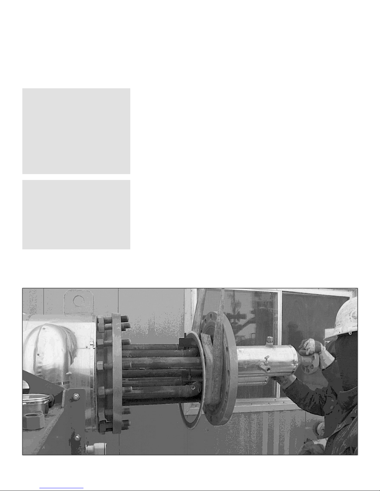
MAINTENANCE
WARNING:
Inspections and tests
included in this section may be
regulated by local, Federal, or
other jurisdictions. Please
review all applicable codes
and regulations prior to
conducting any activities on
CWT equipment.
WARNING:
Performing pressure tests on
the system can be hazardous,
and should only be performed
by trained professionals.
Contact Tecvalco if you have
any questions.
7.15 The gas bundle removal
At least every 15 years the high-pressure coil should be removed and inspected
(this period might vary depending on company policy or local codes). Prior to
removing the coil contact CWT for a replacement gasket and recommended bolt
torque values.
1. Ensure the heater is off and cooled. Pilot extinguished, Robertshaw
gas valve to off and main gas valve shut and locked out.
2. Carefully remove the insulation around the coil flange. Do not dent
the cladding and save all cladding and insulation for re-install.
3. Ensure that no pressure exists in the unit.
3. Remove the coil from the heater.
4. Visually inspect the coil and the can interior for signs of corrosion
or damage.
5. Inspect coil as per appropriate codes (ASME, local corporate
and other).
6. Install new gasket.
7. Install studs and nuts, torque to appropriate specifications (call CWT)
and establish vacuum (see section 7.12).
8. Install all insulation and cladding as per original installation. install
all sheet metal screws in original positions and caulk all seams and
openings to ensure a proper seal is provided.
Page 62
(Figure 7.15)
PN :: HEA -BOI -MANUAL -016 | 20170316

MAINTENANCE
7.16 Inspection checklist
CWT Boiler Inspection Sheet
Company ______________________________________ Technician _________________________________________
Location _______________________________________ Date ______________________________________________
Model _________________________________________ Coil Serial Number _________________________________
Serial Number __________________________________ Coil CRN __________________________________________
Heater Status on arrival (running, on piot, off, cold, etc.) __________________________________________________
Steam temperature (degrees F when firing and warm) ____________________________________________________
Steam pressure (“Hg when firing and warm) ____________________________________________________________
Gas in temperature (degrees F when firing and warm) ____________________________________________________
Gas out temperature (degrees F when firing and warm) __________________________________________________
Stack temperature (degrees F when firing and warm) _____________________________________________________
Station outlet temperature (degrees F when firing and warm) ______________________________________________
Glycol fluid level (trace, 1/4, 1/2, 3/4, full) ______________________________________________________________
Glycol appearance __________________________________________________________________________________
Down stream fuel pressure (PSI) _______________________________________________________________________
Fuel pressure (inches WC) ____________________________________________________________________________
Inspect flame arrestor (clean as needed) ________________________________________________________________
Photos taken (burners, fine tubes) ______________________________________________________________________
Blow out cell and fin tubes ____________________________________________________________________________
Millivolt Reading Control Settings
Side 1 Side 2 (1) _________ Operating steam pressure switch (PSI)
1 ____________ ________________ (2) _________ Operating steam pressure switch (PSI)
2 ______________ ___________________ ____________ High-high steam pressure swtich with ESD (PSI)
3 ______________ ___________________ ____________ Line temperature (down stream temperature) degrees F
4 ______________ ___________________ ____________ Emergency push button (check if needed)
____________ Low water cut-off (check if needed)
____________ Low-low water cut-off with ESD (check if needed)
*Do not tamper with the operating steam temperature
switch or the high-high steam temperature switch
settings unless you have a way to reset them properly.
Combustion Analysis
O2 (%) _________________________ CO2 (%) ______________________________
CO (ppm) _______________________ Efficiency ______________________________
Excess Air (%) ____________________ Stack temperature (degrees F) ____________
Boiler firing rate (BTR/hr) ______________________________________________________________________________
Note condition of insulation, any scale or sign of moisture _________________________________________________
Note condition of B-vent to steel transition piece__________________________________________________________
Comments, please note any work done or adjustments made: _____________________________________________
____________________________________________________________________________________________________
____________________________________________________________________________________________________
PN :: HEA -BOI -MANUAL -016 | 20170316
Page 63

TROUBLESHOOTING
WARNING:
Inspections and tests
included in this section may be
regulated by local, Federal, or
other jurisdictions. Please
review all applicable codes
and regulations prior to
conducting any activities on
CWT equipment.
WARNING:
Performing pressure tests on
the system can be hazardous,
and should only be performed
by trained professionals.
Contact Tecvalco if you have
any questions.
WARNING:
Do not use this boiler if any
part has been under water.
Immediately call a qualified
service technician to inspect the
boiler and to replace any part of
the control system and any gas
control which has been under
wa ter.
8. Troubleshooting
The following is a list of common problems associated with the operation of the
HDL boiler. This list is by no means all-inclusive. Please, feel free to contact Tecvalco to assist with any problems that occur.
8.1 Heater inspection checklist
Please ensure that you completely fill out a copy of the CWT Heater Inspection
Checklist, found in section 7.16, as part of your troubleshooting efforts.
Page 64
PN :: HEA -BOI -MANUAL -016 | 20170316

8.2 Common problems and possible solutions
TROUBLESHOOTING
SYMPTOM
If pilot is out
COMMON CAUSES
Loss of fuel gas supply
Excessive pressure in system caused high-high
steam pressure switch with ESD to activate
High-high steam pressure switch with ESD issue
Low fluid level in heater has caused low fluid
level switch and/or low-low fluid level switch with
ESD to trip
Low fluid level switch issue and/or low-low fluid
level switch with ESD issue
System has exceeded allowable pressure, and the
relief has failed, allowing water to escape.
Unsteady or fluctuating flame
Weak powerpile voltage
Robertshaw gas valve magnet not holding
POSSIBLE CORRECTIONS
Check fuel gas supply.
Review pressure shown on gauge. If excessive,
diagnose cause and fix.
Check switch ESD, and test functionality.
Check for fluid movement in sight glass. Diagnose
cause and fix. Reset ESD if necessary.
Check switches and ESD, and test functionality of
each.
Inspect pressure relief and barrel for exited water.
Diagnose cause of over-pressure and fix. Replace or
repair pressure relief system.
Examine the flame. Is it steady or fluctuating? Is it
lifting off the burners? If so, the combustion may
need tuning. Contact CWT for advice.
Test the voltage to each powerpile. See section 7.6.
Use test 4 (pilot dropout) in section 7.6
If main burner
Line temperature control switch not wired correctly
will not fire
System not requiring heat
Problem with line temperature switch
Steam temperature exceeds setting of discharge
temperature switch
Loss of fuel gas supply
Weak powerpile voltage
Robertshaw gas valve magnet not holding
If system won’t
Loose wiring connection
fire pilot or main
flame
PN :: HEA -BOI -MANUAL -016 | 20170316
Check wiring diagrams (found in section 4.1.5).
Check line temperature control switch to see if it is
turning on and off at desired temperature. Set to
appropriate temperature.
Test functionality of switch. Repair or replace if
necessary.
Review steam tempeature settings. May need review
with CWT. Possible low- or zero-flow situation.
Check fuel gas supply.
Test the voltage to each powerpile. See section 7.6.
Use test 4 (pilot dropout) in section 7.6
Check ESD push buttom wiring and enure connections are tight.
Page 65

TROUBLESHOOTING
SYMPTOM
Heater has lost
vacuum
* Always assume
unit is under
pressure until
proven otherwise
Failure or release
of pressure relief
system
Gas is not being
heated to proper
temperature
COMMON CAUSES
Malfunctioning vacuum gauge
Evaporator is hot with high steam pressure due to
operation
System has exceeded internal presure and relief
has failed.
Possible leakage of fittings, PRV, switches, etc.
Possible leakage in pressure relief system
System has exceeded allowable internal pressure
setting of relief system
Line temperature switch settings
Fuel gas pressure
POSSIBLE CORRECTIONS
Ensure that vacuum is lost and that vacuum gauge is
accurate.
Record steam pressure and steam temperature from
heater. Using these values, review table 10.19.
Inspect pressure relief barrel for exited fluid. If
present, diagnose overpressure cause. Fix and
replace pressure relief system and all fluid.
Test system for leakages using procedure 7.11
Test system for leakages using procedure 7.11.
Diagnose overpressure cause. Repair or replace
relief system and replace all fluids.
Check switch settings. Function test switches. Settings can be found on page 50. Check local codes.
Check fuel gas pressure. It may need to be turned
up or down, depending on requirements.
Line temperature switch location
Gas piping insulation
Gas flow
Safety switch operation
Lost water/fluid
Check line temperature switch for proper location. Is
the switch placed just past the final pressure cut?
It is recommended that the piping be insulated. If it
is not, then the switch in the gas piping may pick up
ambient temperature.
Check gas flow through coil. Potential zero- or lowflow through coil. See section 8.3.
Inspect switches in system to ensure no settings have
been exceeded.
Inspect glycol site glass for fluid level. Find cause
and fix.
Page 66
PN :: HEA -BOI -MANUAL -016 | 20170316

8.3 Potential zero-flow application
The CWT Boiler’s application is typically designed to sense the temperature of
the gas as it exits the gate station after the last pressure cut. If a zero-flow situation exists (where no, or very little gas is flowing through the system) the probe
that is downstream from the facility can be subjected to ambient temperatures
below the set point of the control.
As there is minimal or zero flow, the now-heated gas will not flow past the probe,
and will not signal the heater to stop its firing sequence. With the external insulation on the evaporators being very efficient, the heat being generated cannot
escape and the overall temperature and pressure within the evaporator and heat
exchanger will increase.
As this occurs certain safety devices will begin to operate:
1. The steam temperature will increase beyond the acceptable
temperature of the HTSD, causing the safety device to open the circuit
and stop the main flame from firing.
a) If the unit can release enough heat to the surroundings, the
temperature will drop and the HTSD will automatically reset,
allowing the heater to resume firing as directed by the still cold
downstream temperature probe.
2. If the heat can not be released then the pressure within the
evaporator and condenser will continue to increase, ultimately
surpassing the 5 psi range of the pressure switch. This will open
the electrical circuit, stopping the gas to the main burners, keeping
the unit from firing.
NOTE: The pilot light will remain lit, allowing it to re-fire once the
pressure had dropped below the 3 psi set point.
3. Finally, as the unit continues to release the heat and generates steam
(even without a flame but potentially from the heat stored in the steel
of the housing etc.) the pressure may build to 15 psi at which time the
pressure relief valve will release.
TROUBLESHOOTING
NOTE:
If the line temperature probe is
installed at the outlet of the
high-pressure coil “the set
temperature” must be set
accordingly.
The general rule is that for every
100 psi of pressure drop 7°F/-
13.9°C temperature drop. For
example, if a 500 psi pressure drop
is to occur the outlet temperature of
the coil should be initially set 30°F
above the temperature required
after the last pressure drop i.e if a
temperature at 35°F/1.67°C is required after the last pressure drop,
the line temperature control should
initially be set to 70°F/3.34°C.
The boiler should then be
monitored for proper operation.
WARNING:
Performing pressure tests on
the system can be hazardous,
and should only be performed
by trained professionals.
Contact Tecvalco if you have
any questions.
PN :: HEA -BOI -MANUAL -016 | 20170316
Page 67

OPTIONAL EQUIPMENT AND ACCESSORIES
9. Optional equipment and accessories
9.1 High-temperature shut down
There are three options.
Page 68
PN :: HEA -BOI -MANUAL -016 | 20170316

9.2 High-temperature shut down installation drawing
OPTIONAL EQUIPMENT AND ACCESSORIES
PN :: HEA -BOI -MANUAL -016 | 20170316
Page 69

GLOSSARY
10. Glossary
10.1. Low-pressure evaporator
An evaporator is a closed vessel in which water or other fluid is heated to
a gaseous state for heating applications. In the CWT evaporator the
pressure produced is less than 15 psi, hence it’s a low-pressure evaporator.
10.2. Inches of mercury:
In Hg or “Hg is a measuring unit for pressure”. It is defined as the pressure
exerted by a column of mercury of 1 inch in height at 32°F (0°C) at the
standard acceleration of gravity.
1 in Hg = 3,386.389 pascals at 0°C.
In English units: 1 inHg = .491098 psi, or 2.036254 inHg = 1 psi.
10.3. Pascal (pa):
It is a measure of force per unit area i.e. equivalent to one newton per
square meter or one joule per cubic meter.
10.4. Pressure (P):
Is the force per unit area applied to an object in a direction perpendicular
to the surface.
10.5. Gauge pressure:
Is the pressure relative to the local atmospheric or ambient pressure.
10.6. Inches water column:
Instead of using pressure as units of measurement, inches of water are
commonly used in airflow applications in HVAC (Heat, Ventilating and Air
Conditioning) because the pressure measurements are very minute.
10.7. British Thermal Unit (BTU):
The British Thermal Unit (BTU or Btu) is a unit of energy used in the power,
steam generation, heating and air conditioning industries. The term “BTU”
is used to describe the heat value (energy content) of fuels, and also to
describe the power of heating and cooling systems. One BTU is
approximately 1,054 - 1,060 joules (J).
Page 70
10.8. MBTU:
One thousand BTU
10.9. MMBTU:
One million BTU
PN :: HEA -BOI -MANUAL -016 | 20170316

10.10. Latent heat:
is the amount of energy released or absorbed by a chemical
substance during a change of state (i.e. solid, liquid, or gas), or a
phase transition
10 .11. Vacuum:
A vacuum reference can be thought of as the opposite of a gage reference.
Vacuum references are notated with “V”, for example PSIV or “HgV”
10.12. Differential:
Differential pressure measurement is the difference between two unknown
pressures. Output is zero when the two pressures are the same, regardless
of magnitude. Differential pressures are notated as “D” (PSID).
GLOSSARY
10.13. Absolute:
As previously described, the zero point of an absolute reference is the
absence of all matter. There is no pressure at absolute zero. All absolute
pressure measurements made are therefore positive. Absolute pressure
measurements are abbreviated with an “A”. For example, 0 PSIA o6 6”HgA.
10.14. Gage:
To ignore the effects of changing weather, altitude or depth, a “Gage”
pressure reference is sometimes useful. This reference measures
pressure relative to the local atmosphere. Changes in local atmospheric
pressure occur due to weather, or if the instrument is moving because of
changes in altitude and/or depth. Gage pressure is denoted as “G”
or PSIG.
10.15. Heat required to raise the temperature of a material:
Q1 = Heat required to raise temperature
W = Pounds of material
CP = Specific heat of material (Btu/lb-ºF)
T = Temperature rise of material
(TFinal - TInitial) ºF
PN :: HEA -BOI -MANUAL -016 | 20170316
Page 71

GLOSSARY
10.16. SCFH:
Standard Cubic Feet per Hour
1 PSI = 27.68”WC (inches of water column)
1 PSI = 2.036”Hg (inches of mercury)
1 PSI = 51.715 mmHg or Torr
1 PSI = 0.068947 Bar
1 PSI = 0.06804 Atmospheres
(Note that 1 Bar is not exactly 1 atmosphere)
1 PSI = 6.8947 KiloPascals or KPa
1 PSI = 0.0703 Kg/cm2
1 PSI = 2.307 feet of water
10.17. Peak load:
Measurement of the maximum amount of energy delivered at a
point of time
10.18. Flue gas:
Combustion gases that are vented to the atmosphere. The equation below
providesanapproximationofthepressuredifference,ΔP,(betweenthe
bottom and the top of the flue gas stack) that is created by the draft.
ΔP = Available pressure difference, in Pa
C = 0.0342
a = Atmospheric pressure, in Pa
h = Height of the flue gas stack, in m
To = Absolute outside air temperature, in K
Ti = Absolute average temperature of the flue gas inside the stack, in K
Page 72
PN :: HEA -BOI -MANUAL -016 | 20170316

10.19 CWT pressure and temperature chart
This chart can also be used as a diagnostic tool as the pressure and temperature
of the CWT Boiler steam chamber should fall on this line. If the steam
temperature and pressure do not meet the line, there might be a problem, which
requires further investigation.
Boiling Point of Water at various Pressures - Gauge Pressure
(Vacuum and Positive Pressure)
20
17.5
15
12.5
10
7.5
5
2.5
0
120/49
-2.5
-5
S te a m P re ss ur e
-7.5
-10
-12.5
(po si tive i n P SI - negati ve in INHG )
-15
-17.5
-20
-22.5
-25
130/54
140/60
150/66
160/71
170/77
180/82
190/88
200/93
210/100
220/104
B oi ling Poi nt of Wa te r Tempe ratu re De g F / Deg C
230/110
240/116
250/121
GLOSSARY
260/127
270/132
280/138
The CWT Boiler typically operates with negative pressure (vacuum), and is
usually in the operating range of –6 to –26 In Vacuum Hg or below 0 psig. If a
CWT heating boiler is operating at close to 0 psig and close to 100°C (212°F) it
may be the result of very low process load or an indication of a loss of vacuum.
In every case, the most important indicator of the condition of a CWT Boiler is
the pressure and temperature in the evaporator. Another very important measure
is the temperature of the process gas in and out of the evaporator. There should
be a significant increase in the temperature of the high-pressure gas as it passes
through the evaporator.
PN :: HEA -BOI -MANUAL -016 | 20170316
(Figure 10.19)
Page 73

SPARE PARTS LIST
11. Spare parts list
Associated Boiler Model Part Number Description
140, 385, 770 BAR-PLA-30 30 Gal Plastic Barrell c/w Lid
140, 385, 770 BOL-LYNCHPIN-.188 3/16” Lynch Pin
140, 385, 770 BUR-B-.438-27 7/16” Spud Orifice Brass
140, 385, 770 BUR-SFB-098044-000 Swordfish Burner Orifice Cover
140, 385, 770 BUR-SFB-098047-000 Swordfish Burner B&G
140, 385, 770 CTR-BAR-142400-63 McD&M Series 63 LWCO
140, 385, 770 CTR-BAR-143100-63-M Series 63-M w/reset LWCO
140, 385, 770 CTR-CT-BBQ-IGN Canadian Tire Ignitor System
140, 385, 770 CTR-PADTHERM Pilot Ass Double Thermopile
140, 385, 770 CTR-SP-289H-41 289 BP Fisher Reg 1”npt 1-4.5p
140, 385, 770 CTR-SP-HSR-CDGBMYN HSR 1/4 orifice”-12.5”-20” WC
140, 385, 770 CTR-SP-PRV-13-202-08 Conbraco 1” PSV 15psig
140, 385, 770 CTR-SS-700-C506 700-C506 Robertshaw Gas Valve
140, 385, 770 CTR-SS-L404F1060 Honeywell switch 2-15psi
140, 385, 770 CTR-SS-L4079B1033 Honeywell w/man reset 15psi
140, 385, 770 FIE-ZB4BS54 Mush PB Operator 40MM
140, 385, 770 FIE-ZB4BZ009 PB Mounting Bezel
140, 385, 770 FIE-ZBE102 Contact block 1-N/C
140, 385, 770 FIE-ZBY9330 E-Stop Legend plate
140, 385, 770 GAU-2.5-.25B-M30-30P-L 2-1/2” x 1/4” 30-30 Psi Gauge
140, 385, 770 GAU-4-.5B-2000P 4” x 1/2” 0-2000 Psi BM Gauge
140, 385, 770 GAU-INCH-2.5-.25-0-15 2-1/2” x 1/4” 0-15 Inch Gauge
140, 385, 770 HEA-IGNBOX-ASSY 4” x 4” x 2” CWT Ignition Box
140, 385, 770 HEA-IGNHH-ASSY CWT Portable Hand Held Ignitor
140, 385, 770 HOS-GFAH-.75-18 3/4” x 18” F x F Flex hose
140, 385, 770 VAV-NDL-MXF-.5 1/2” CS MxF Needle Valve
140, 385, 770 WIR-SHCAB-1P-18G 18 Ga x 1 Pair Shielded Cable
140, 385, 770 WIR-SPW-7MM-HD 7mm HD Spark Plug Wire
140, 385, 770 THR-SS-1-.5-9-.250 1” x 1/2” x 9” x .250 SS THR
140, 385, 770 GAU-3-9-50-500-S 3” x 9” 50-500 Deg Gauge
140, 38 5 CTR-T675A-1565 Honeywell 0-100F American Cust
385, 770 FLA-FAFBC-20-4C 20” Flame Arr Flash Back Cell
385, 770 GSK-304SS-FLEX-150-4 4” 150# 304SS Flex Gasket
385, 770 GSK-NA1001-RD-20-18.625 20”ODx18.625”ID Gasket
385, 770 HEA-10-SGLASS-PAI-ASSY 10” Sight Glass Paint Assembly
140 FIR-BVENT-6-5 6” x 5’ B-Vent Section
140 FIR-BVENT-HWCAP-6 6” Hi-Wind Cap
140 FLA-FAFBC-15-4C 15” Flame Arr. Flash Back Cell
140 HEA-140-3-1100 140 Boiler Stack Support Assm.
Page 74
PN :: HEA -BOI -MANUAL -016 | 20170316

SPARE PARTS LIST
Associated Boiler Model Part Number Description
140 GSK-NA1001-RD-14.875-13.5 15” A-Fire flame cell gasket
140 GSK-GR-RD-20.5-14.125-26 20.5 ODx14.125ID 26H Graphite
140 HEA-6-SGLASS-PAI-ASSY 6” Sight Glass Paint Assembly
140 THR-SS-.75-.5-4-.250 3/4” x 1/2” x 4” x .250 SS THR
140 GAU-3-4-M40-160-S 3” x 4” 40-160 Deg Gauge
140 GSK-N1001-RD-10.625-6.625-8 EXHAUST STACK GASKET
385 FIR-BVENT-8-3 8” x 3’ B-Vent Section
385 FIR-BVENT-8-5 8” x 5’ B-Vent Section
385 FIR-BVENT-RAINCAP-8 8” B-Vent Rain Cap
385 HEA-BVENT-SUPPORT-8 8” Bvent Stack Support
385 GSK-NA1001-RD-12.5-8.625-8 12.5 “Od x 8.625”id 8 hole gaskeT
770 FIR-BVENT-12-3 12” x 3’ B-Vent Section
770 FIR-BVENT-RAINCAP-12 12” B-Vent Rain Cap
770 GSK-NA1001-RT-47/43-24/20 New 770 Square Gasket
770 HEA-770-2C-800A Stack Adapter Assembly
770 CTR-SS-T678A-1015 100 F 20’Capillary-US only
770 GSK-NA1001-RD-16-12.625-12 16”OD X 12.625”ID 12 HOLE GASKET
Options
Associated Boiler Model Part Number Description
140, 38 5 CTR-COIL-HTSD-1F High temp shut-down, Farenheit
770 CTR-COIL-HTSD-2F High temp shut-down, Farenheit
140, 38 5 CTR-COIL-HTSD-1C High temp shut-down, Celsius
140, 385, 770 CTR-SS-93560 6 cfm vacuum pump - 93560
140, 385, 770 CTR-SS-19310 6 cfm vacuum pump hose 3/8 inch
140, 385, 770 COS-VAC-OIL Oil for vacuum pump, 4 litre container
140, 385, 770 CTR-SP-T14399T0012 HSR spring, 6” wc to 8” wc (Yellow)
140, 385, 770 CTR-SP-T14405T0012 HSR spring, 8” to 10” wc (Black)
140, 385, 770 CTR-SP-T14400T0012 HSR spring, 10” wc to 12.5” wc (Silver)
140, 385, 770 CTR-SP-T14401T0012 HSR spring, 12.5” to 20” wc (Gray)
PN :: HEA -BOI -MANUAL -016 | 20170316
Page 75

WARRANTY
12. Equipment warranty -
repair and return procedure
This warranty shall apply to items manufactured by Tecvalco, and supplied to Buyer
for use within a Tecvalco authorized distribution territory. Items manufactured by
Tecvalco and supplied to the Buyer for use in locations within Canada or the United
States are subject to the equipment warranty as applicable.
Warranty
During the warranty period subject to the limitations herein, Tecvalco warrants that
the product manufactured by any Tecvalco company and supplied to Buyer by
Tecvalco or through an authorized Tecvalco distributor shall be free from defects in
materials and workmanship and will conform to applicable specifications and
drawings. This warranty extends only to the original end use customer and is not
transferable. Tecvalco’s liability herein, whether based upon breach of warranty or
contract or negligence in manufacture, shall be limited to replacement, repair or
refund of a prorated purchase price paid by Buyer at Tecvalco’s election of all such
defective or nonconforming items, provided that this warranty shall apply only where
Buyer has given Tecvalco written notice of such defects or nonconformity within the
applicable warranty period after delivery by Tecvalco of such items to the Buyer.
In no event shall Tecvalco’s total liability hereunder exceed the price paid by Buyer
to Tecvalco for such item. Tecvalco shall have the right prior to return to inspect at
Buyer’s facility any items claimed to be defective or nonconforming.
Page 76
Warranty Period
The warranty period for Tecvalco manufactured products commences from the
date of invoice to the Buyer and except as noted below, continues for a period of
18 months (the Warranty Period). Exceptions to this warranty period are as follows:
items not manufactured by Tecvalco will carry the remaining warranty and related
terms and conditions of the original manufacturer, where enforceable.
The foregoing constitutes the sole and exclusive remedy of the Buyer and exclusive
liability of Tecvalco and is in lieu of any and all other warranties expressed or implied
or statutory as to merchant liability, fitness for purpose sold, description, quality,
productiveness or any other matter. Without limiting the foregoing, in no event shall
Tecvalco or its suppliers be liable to Buyer for any incidental, special, punitive,
exemplary or consequential damages experienced by either Buyer or a third party
(including, but not limited to loss of profits or loss of use). Tecvalco is not liable for
damages for any cause whatsoever (whether based in contract, tort, or otherwise) in
excess of the amount paid for the item.
PN :: HEA -BOI -MANUAL -016 | 20170316

Returns
Repair of all defective or malfunctioning products by Tecvalco will be made at a
location determined solely by Tecvalco. Return authorization must be obtained in
writing from Tecvalco including those for repair, Buyer’s rights to repair or
replacement are governed by this warranty.
Shipping
The Buyer shall pay the cost of shipping the products from the Buyer’s facility to a
Tecvalco designated repair location. Tecvalco will return repaired or replaced
equipment at Buyer’s cost to the Buyer’s facility. Buyer shall be responsible for
payment of customs duties, importation fees, VAT or other like charges.
Repair Charges
In-warranty period repairs will be made at no charge to Buyer provided that failure
is not due to misuse, mishandling or act of God. An in-warranty product that is
returned for repair and found not to be defective or malfunctioning or for which
failure is caused by misuse, mishandling or act of God, shall be subject to Tecvalco’s
actual costs for testing and handling.
WARRANTY
The costs of out-of-warranty repairs including return shipment are subject to charges
as quoted by Tecvalco. Buyer’s acceptance of these charges is necessary before
repairs will be made. Return shipping shall use the most economical shipment means
available. Upon request of the Buyer, Tecvalco will use other means of shipment, in
which case Buyer shall pay the cost of shipping directly.
Repair Warranty
Repair work performed on in-warranty products is warranted for the remainder of
the original warranty period or six (6) months, whichever is greater. Repair work
performed on out-of-warranty equipment is warranted for six (6) months from the
date of shipment of the repaired unit from Tecvalco. This six (6) month period covers
only the actual repair(s) made to the product and is exclusive of potential non-related
faults that may occur during the six (6) month period.
Alteration to Equipment Purchased
Modification or alteration to purchased products by anyone, other than that
specifically authorized by Tecvalco, shall void and nullify, in its entirety, all warranty
provisions set forth in the preceding.
Engineering Changes
Tecvalco reserves the right to upgrade and modify product items ordered without
prior approval or modification to Buyer and without incurring any obligation or
liability to make the same or similar changes in items previously manufactured.
Post-Sale Support
Please contact your authorized Tecvalco distributor or call Tecvalco Technical Support
at 1-877-879-4748.
PN :: HEA -BOI -MANUAL -016 | 20170316
Page 77

APPENDIX A:
CWT 140,000 BTU/HR BOILER PACKING LIST
ITEM PART NUMBER PART TITLE PART DESCRIPTION QTY
1 CTR-SP-289H-41 289 BP FISHER REGUL ATOR 1” NPT, 1-4.5p 1
2 CTR-SP-HSR-CHCBMY Y HSR REGULATOR HSR-1/2” ORIFICE, 10”-12.5” w.c. 1
3 FIC-CMC1216N-S316 CONNECTOR 3/4” T x 1” MNPT SST CONNECTOR 1
4 FIT-SST-BUSH-1-.25 BUSHING 1” x 1/4” SCH40 SST BUSHING 1
5 FIT-SST-NIP-1-2 NIPPLE 1” x 2” SCH40 SST NIPPLE 2
6 FIT-SST-NIP-1-4 NIPPLE 1” x 4” SCH40 SST NIPPLE 1
7 FIT-SST-NIP-1-6 NIPPLE 1” x 6” SCH40 SST NIPPLE 1
8 FIT-SST-TEE-150-1 TEE 1” 150#NPT 316 TEE 2
9 GAU-INCH-2.5-.25-0-15 GAUGE 2-1/2” x 1/4” 0-15 INCH GAUGE 1
10 VAV-SS-B-1-2000-T-FP BALL VALVE 1” 2000# SS FP BALL VALVE 1
11 FIR-BVENT-6-3 EXHAUST STACK 6” x 3’ B-VENT SECTION 1
12 FIR-BVENT-6-5 EXHAUST STACK 6” x 5’ B-VENT SECTION 1
13 FIR-BVENT-HWCAP-6 E XHAUST STACK 6” HI-WIND CAP 1
14 HE A-140-3-1100 EXHAUST STACK STACK SUPPORT ASSM. 140 BOILER 1
15 BOL-GR5-.5-1.5 BOLT NC, GR ADE 5, 1/2” x 1-1/2” 12
16 NUT-GR5-.5 NC NUT 1/2” GRADE 5 NC NUT 12
17 WAS -GR5-F-.5 WASHER 1/2” GRADE 5 FL AT WASHER 24
18 CTR-HIGH-TEMP-SHUT-DOWN ASSEMBLY HI-TEMPERATURE SHUT DOWN ASSEMBLY AS REQUIRED
19 CTR-SS-T675A-1565 REMOTE TEMP CONTROL HONEYWELL 0-100F 1
20 ELE-A10P8 ELECTRICAL PANEL PANEL, 8” x 6” 1
21 ELE-BOX-A1086CHQRFG ELECTRICAL BOX HOFFMAN 10x8x6 FIB JB 1
22 FIE-5232 CONDUIT C16104 STR LIQ TIGHT CON 1/2” 2
23 FIE-AL-NIP-.5-C NIPPLE 1/2” x CLOSE ALUMINUM NIPPLE 1
24 FIE-CSA050-30 FLEX CONDUIT 1/2” LIQUID TITE FLEX CONDUIT 5.25 m
25 FIE-GK50N ENCLOSURE 1/2” GK50N ENCLOSURE 35/85 GSK 1
26 FIE-K50A BACK PLATE 1/2” ALUM K50A BLANK BACKPLATE 1
27 FIE-LB50A ALUMINUM CONDUIT 1/2” LB50A ALUMINUM COND BODY 1
28 FIE-ST-050-464 CONNECTOR 1/2” STO50-464 STAR TECK CONN 2
29 FIE-UNY50NRA UNION 1/2” XP ALUM. UNION UNY50NR A 1
30 GAU-4-.5B-2000P GAUGE 4” x 1/2” 0-2000 PSI BM GAUGE 2
31 HE A-BOIL-MANUAL-006 M ANUAL BOILER MANUAL REVISED, REV 6 3
32 HEA-QA-MANUAL MANUAL QUALITY ASSURANCE MANUAL 3
33 NUT-LOCK-.75 LOCK NUT 3/4” LOCK NUT 3
34 THR-THERMOWELL TBD BY SALES
35 WIR-SHCAP-1P-18G CABLE 18 GAUGE x 1 PAIR SHIELDED CABLE 35 m
FUEL GAS HEADER ASSEMBLY - P103-140-3
EXHUAST STACK ASSEMBLY
HI TEMP SHUT DOWN ASSEMBLY
Page 78
PN :: HEA -BOI -MANUAL -016 | 20170316

APPENDIX B:
CWT 385,000 BTU/HR BOILER PACKING LIST
ITEM PART NUMBER PART TITLE PART DESCRIPTION QTY
1 HEA-GAS-HEADER-ASSM GAS TR AIN JOB SPECIFIC GAS HEADER ASSEMBLY 1
2 FIR-BVENT-8-3 EXHAUST STACK 8” x 3’ B-VENT SECTION 1
3 FIR-BVENT-8-5 EXHAUST STACK 8” x 5’ B-VENT SECTION 1
4 FIR-BVENT-RAINCAP-8 EXHAUST STACK 8” B-VENT R AIN CAP 1
5 HEA-BVENT-SUPPORT-8 EXHAUST STACK 8” BVENT STACK SUPPORT 1
6 BOL-GR5-.5-1.5 BOLT NC, GR ADE 5, 1/2” x 1-1/2” 12
7 NUT-GR2-.5 NC NUT 1/2” GRADE 2 NC NUT 12
8 WAS-GR5-F-.5 WASHER 1/2” GR ADE 5 FLAT WASHER 24
9 CTR-HIGH-TEMP-SHUT-DOWN ASSEMBLY HI-TEMPERATURE SHUT DOWN ASSEMBLY AS RE-
QUIRED
10 GAU-3-6-50-500-S GAUGE 3” x 6” 50-500 DEG GUAGE 1
11 CTR-SS-T675A-1565 REMOTE TEMP CONTROL HONEYWELL TEMP CON. 0 - 100F 1
12 ELE-A10P8 ELECTRICAL PANEL PANEL, 8” x 6” 1
13 ELE-BOX-A1086CHQRFG ELECTRICAL BOX HOFFM AN 10x8x6 FIB JB 1
14 FIE-5232 CONDUIT C16104 STR LIQ TIGHT CON 1/2” 2
15 FIE-AL-NIP-.5-C NIPPLE 1/2” x CLOSE ALUMINUM NIPPLE 1
16 FIE-CSA050-30 FLEX CONDUIT 1/2” LIQUID TITE FLEX CONDUIT 5.25 m
17 FIE-GK50N ENCLOSURE 1/2” GK50N ENCLOSURE 35/85 GSK 1
18 FIE-K50A BACK PLATE 1/2” ALUM K50A BLANK BACKPLATE 1
19 FIE-LB50A ALUMINUM CONDUIT 1/2” LB50A ALUMINUM COND BODY 1
20 FIE-ST-050-464 CONNECTOR 1/2” STO50-464 STAR TECK CONN 2
21 FIE-UNY50NRA UNION 1/2” XP ALUM. UNION UNY50NRA 1
22 GAU-4-.5B-2000P GAUGE 4” x 1/2” 0-2000 PSI BM GAUGE 2
23 HEA-BOI-MANUAL-006 M ANUAL BOILER MANUAL REVISED, RE V 6 3
24 HEA-QA-MANUAL MANUAL QUALITY ASSURANCE MANUAL 3
25 THR-THERMOWELL TBD BY SALES
26 WIR-SHCAP-1P-18G CABLE 18 GAUGE x 1 PAIR SHIELDED CABLE 31 m
27 NUT-GR5-LOC-.75 NUT 3/4” NYLON LOCK NUT 3
FUEL GAS HEADER ASSEMBLY - P103-385
EXHUAST STACK ASSEMBLY
HI TEMP SHUT DOWN ASSEMBLY
PN :: HEA -BOI -MANUAL -016 | 20170316
Page 79

APPENDIX C:
CWT 770,000 BTU/HR BOILER PACKING LIST
ITEM PART NUMBER PART TITLE PART DESCRIPTION QTY
1 HEA-GAS-HEADER-ASSM GAS TRAIN JOB SPECIFIC GAS HEADER ASSEMBLY 1
2 FIR-BVENT-12-3 EXHAUST STACK 12” x 3’ B-VENT SECTION 3
3 FIR-BVENT-RAINCAP-12 EXHAUST STACK 12” B-VENT RAIN CAP 1
4 HEA-770-2-800 EXHAUST STACK 770 BOILER/EVAP STACK SUPPORT 1
5 BOL-GR5-.5-1.5 BOLT NC, GR ADE 5, 1/2” x 1-1/2” 12
6 NUT-GR2-.5 NC NUT 1/2” GRADE 2 NC NUT 18
7 WAS -GR5-L-.5 LOCK WASHER 1/2” GR ADE 5 LOCK WASHER 24
8 CTR-HIGH-TEMP-SHUT-DOWN ASSEMBLY HI-TEMPERATURE SHUT DOWN ASSEMBLY AS REQUIRED
9 GAU-3-12-50-500-S GAUGE 3” x 12” 50-500 DEG GUAGE 1
10 CTR-SS-T678A-1015 REMOTE TEMP CONTROL T678A-1015 Honeywell Temp. Con. 1
11 ELE-A10P8 ELECTRICAL PANEL PANEL, 8” x 6” 1
12 ELE-BOX-A1086CHQRFG ELECTRICAL BOX HOFFMAN 10x8x6 FIB JB 1
13 FIE-5232 CONDUIT C16104 STR LIQ TIGHT CON 1/2” 2
14 FIE-AL-NIP-.5-C NIPPLE 1/2” x CLOSE ALUMINUM NIPPLE 1
15 FIE-CSA050-30 FLEX CONDUIT 1/2” LIQUID TITE FLEX CONDUIT 5.5 m
16 FIE-GK50N ENCLOSURE 1/2” GK50N ENCLOSURE 35/85 GSK 1
17 FIE-K50A BACK PLATE 1/2” ALUM K50A BLANK BACKPLATE 1
18 FIE-LB50A ALUMINUM CONDUIT 1/2” LB50A ALUMINUM COND BODY 1
19 FIE-ST-050-465 CONNECTOR 1/2” STO50-465 STAR TECK CONN 2
20 FIE-UNY50NRA UNION 1/2” XP ALUM. UNION UNY50NRA 1
21 GAU-4-.5B-2000P GAUGE 4” x 1/2” 0-2000 PSI BM GAUGE 2
22 HE A-BOI-M ANUAL-006 M ANUAL BOILER MANUAL REVISED, REV 6 3
23 HEA-QA-MANUAL MANUAL QUALITY ASSURANCE MANUAL 1
24 THR-THERMOWELL TBD BY SALES
25 WAS -GR5-F-.5 WASHER 1/2” GRADE 5 FL AT WASHER 6
26 WIR-SHCAP-2P-18G CABLE 18 GAUGE x 2 PAIR SHIELDED CABLE 35 m
FUEL GAS HEADER ASSEMBLY - P103-770
EXHUAST STACK ASSEMBLY
HI TEMP SHUT DOWN ASSEMBLY
Page 80
PN :: HEA -BOI -MANUAL -016 | 20170316
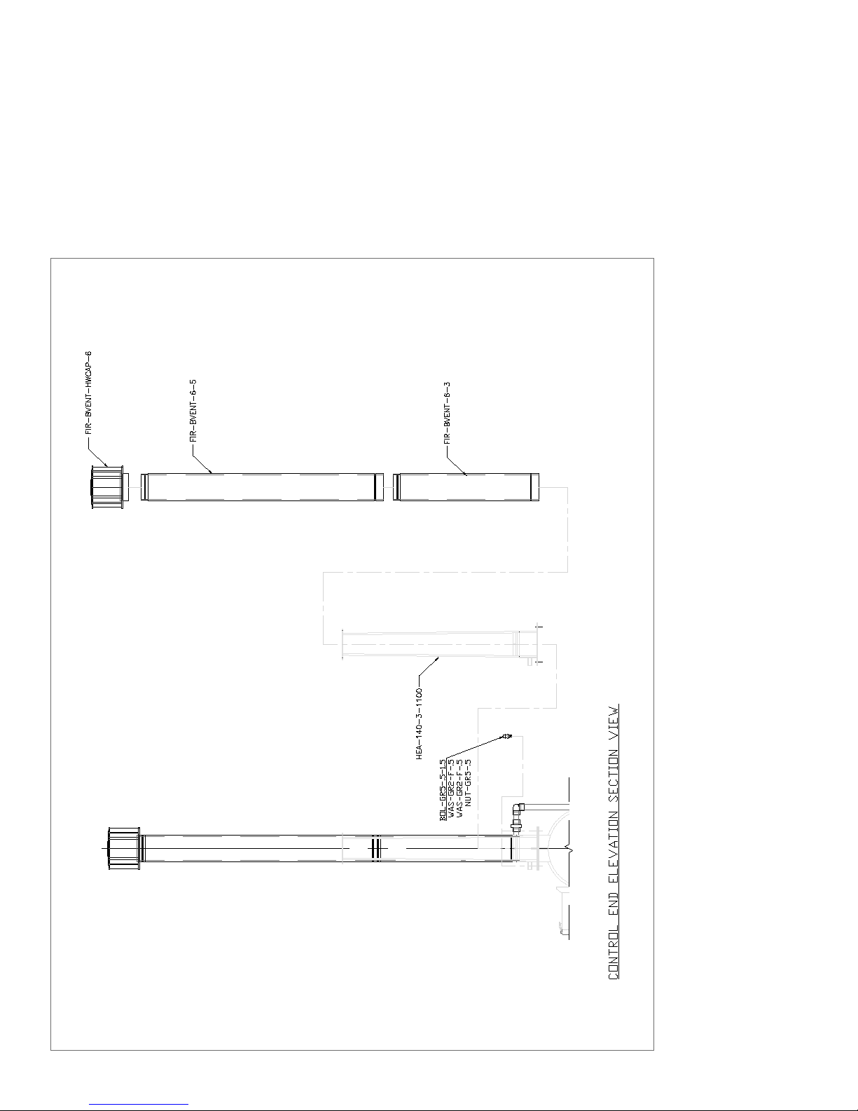
APPENDIX D:
CWT 140 Boiler Stack Assembly
PN :: HEA -BOI -MANUAL -016 | 20170316
Page 81

WARNING
APPENDIX E:
CWT 385 Boiler Stack Assembly
Page 82
PN :: HEA -BOI -MANUAL -016 | 20170316

APPENDIX F:
CWT 770 Boiler Stack Assembly
WARNING
PN :: HEA -BOI -MANUAL -016 | 20170316
Page 83

APPENDIX G:
CWT 140 Burner Assembly and Cross-Section Drawings
Page 84
PN :: HEA -BOI -MANUAL -016 | 20170316

PN :: HEA -BOI -MANUAL -016 | 20170316
Page 85

APPENDIX H:
CWT 385 Burner Assembly and Cross-Section Drawings
Page 86
PN :: HEA -BOI -MANUAL -016 | 20170316

PN :: HEA -BOI -MANUAL -016 | 20170316
Page 87

APPENDIX I:
CWT 770 Burner Assembly and Cross-Section Drawings
Page 88
PN :: HEA -BOI -MANUAL -016 | 20170316

PN :: HEA -BOI -MANUAL -016 | 20170316
Page 89
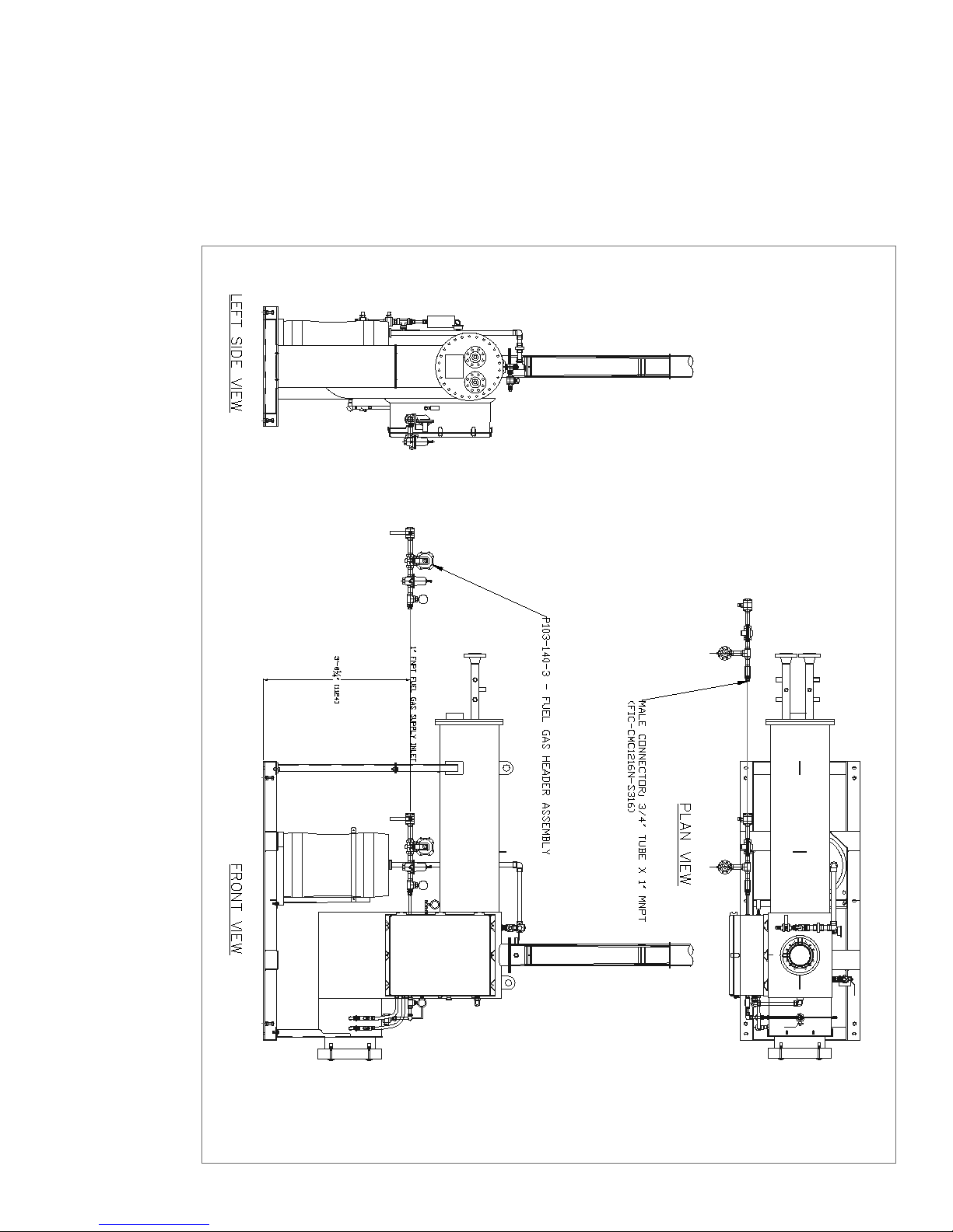
APPENDIX J:
CWT 140 Fuel Gas Train
Page 90
PN :: HEA -BOI -MANUAL -016 | 20170316
 Loading...