

Page 1

V-TWIN
TECUMSEH
ENGINE
Small Engine Parts
Page 2

TABLE OF CONTENTS
CHAPTER 1. GENERAL INFORMATION
CHAPTER 2. AIR CLEANERS
CHAPTER 3. CARBURETORS AND FUEL SYSTEMS
CHAPTER 4. GOVERNORS AND LINKAGE
CHAPTER 5. ELECTRICAL SYSTEMS
CHAPTER 6. IGNITION
CHAPTER 7. INTERNAL ENGINE AND DISASSEMBLY
CHAPTER 8. ENGINE ASSEMBLY
CHAPTER 9. TROUBLESHOOTING AND TESTING
CHAPTER 10. ENGINE SPECIFICATIONS
All rights reserved. No part of this book may be reproduced or transmitted, in any form or by any
means, electronic or mechanical, including photocopying, recording or by any information storage and
retrieval system, without permission in writing from Tecumseh Products Company Training Department
Manager.
Copyright © 2000 by Tecumseh Products Company
i
Page 3

TABLE OF CONTENTS
GENERAL INFORMATION
Engine Identification ................................................................................................1-1
Interpretation of Engine Identification ......................................................................1-1
Short Blocks ............................................................................................................1-2
Fuels........................................................................................................................1-2
Engine Oil ................................................................................................................1-3
Basic Tune-Up Procedure .......................................................................................1-4
Storage....................................................................................................................1-4
AIR CLEANERS
General Information.................................................................................................2-1
Operation.................................................................................................................2-1
Components ............................................................................................................2-1
Troubleshooting and Testing....................................................................................2-1
Service.....................................................................................................................2-2
(by subject)
Page
CARBURETORS AND FUEL SYSTEMS
General Information.................................................................................................3-1
Float Style Carburetors............................................................................................3-1
Operational Circuits Series 7 Carburetor.................................................................3-1
Testing .....................................................................................................................3-3
Carburetor Disassembly Procedure ........................................................................3-5
Inspection ................................................................................................................3-7
Carburetor Re-Assembly .........................................................................................3-7
Throttle Shaft and Plate...................................................................................3-7
Choke Shaft and Plate.....................................................................................3-8
Fuel Bowl Assembly ........................................................................................3-8
Impulse Fuel Pumps................................................................................................3-9
Impulse Fuel Pump Service...........................................................................3-10
GOVERNORS AND LINKAGE
General Information.................................................................................................4-1
Operation.................................................................................................................4-1
Troubleshooting.......................................................................................................4-1
Engine Speed Adjustments .....................................................................................4-1
Engine Overspeed...........................................................................................4-2
Engine Surging ................................................................................................4-2
Governor Service
Static Adjustment - Governor ..........................................................................4-2
Governor Gear and Shaft Service ...................................................................4-3
Governor Shaft Replacement ..........................................................................4-3
ii
Page 4

TABLE OF CONTENTS (continued)
Speed Controls and Linkage ...................................................................................4-3
Synchronizing the Carburetors ................................................................................4-4
Choke Synchronization............................................................................................4-5
ELECTRICAL SYSTEMS
General Information.................................................................................................5-1
Operation.................................................................................................................5-1
Converting Alternating Current to Direct Current.....................................................5-2
Components
Battery ............................................................................................................5-2
Wiring..............................................................................................................5-2
Condition.........................................................................................................5-2
Wire Gauge.....................................................................................................5-2
Electrical Terms .......................................................................................................5-3
Basic Checks...........................................................................................................5-3
Charging Circuit.......................................................................................................5-4
3 Amp D.C. 5 Amp A.C. Alternator .........................................................................5-4
Diode Replacement ........................................................................................5-4
Checking the System......................................................................................5-5
16 Amp Alternator System with External Regulator.................................................5-5
Troubleshooting Electrical Charging Circuit Flow Chart ..........................................5-6
Voltage Regulators ..................................................................................................5-7
Fuel Shut-Down Solenoids ......................................................................................5-7
Low Oil Pressure Sensor Testing.............................................................................5-7
Starting Circuit .........................................................................................................5-8
Testing Procedure Starting Circuit ..................................................................5-8
Troubleshooting Electrical Starter Circuit Flow Chart .....................................5-9
Electric Starter Service ..........................................................................................5-10
12 Volt Electric Starter ..................................................................................5-10
Inspection and Repair...................................................................................5-11
Brush Holder.................................................................................................5-12
Brush Replacement ......................................................................................5-12
Page
IGNITION
General Information.................................................................................................6-1
Operation
Solid State Ignition System (CDI) ............................................................................6-1
Components ....................................................................................................6-1
Testing Procedure............................................................................................6-2
Service
Spark Plug Service ..........................................................................................6-3
Conditions Causing Frequent Spark Plug Fouling...........................................6-3
Ignition Timing .........................................................................................................6-3
Service Tips.............................................................................................................6-4
iii
Page 5

TABLE OF CONTENTS (continued)
INTERNAL ENGINE AND DISASSEMBLY
General Information.................................................................................................7-1
Lubrication Systems ................................................................................................7-1
Disassembly Procedure...........................................................................................7-1
Disassembly of Cylinder Heads...............................................................................7-4
Valves ..............................................................................................................7-5
Valve Guides ...................................................................................................7-5
Valve Springs...................................................................................................7-6
Push Rods .......................................................................................................7-6
Valve Seats......................................................................................................7-6
Internal Engine Component Inspection
Cylinders..........................................................................................................7-7
Pistons.............................................................................................................7-8
Rings ...............................................................................................................7-9
Connecting Rods ...........................................................................................7-10
Crankshafts and Camshafts ..........................................................................7-11
Mechanical Compression Release ................................................................7-12
Valve Lifters ...................................................................................................7-13
Crankcase Breather.......................................................................................7-13
Cylinder Cover...............................................................................................7-13
Page
ENGINE ASSEMBLY
Engine Assembly.....................................................................................................8-1
TROUBLESHOOTING AND TESTING
Engine Knocks.........................................................................................................9-1
Engine Overheats....................................................................................................9-1
Surges or Runs Unevenly........................................................................................9-1
Engine Misfires ........................................................................................................9-1
Engine Vibrates Excessively....................................................................................9-2
Breather Passing Oil................................................................................................9-2
Excessive Oil Consumption.....................................................................................9-2
Lack Power..............................................................................................................9-2
ENGINE SPECIFICATIONS
TVT691 Engine Specifications...............................................................................10-1
Torque Specifications ............................................................................................10-3
Service Tool List ....................................................................................................10-4
iv
Page 6
CHAPTER 1. GENERAL INFORMATION
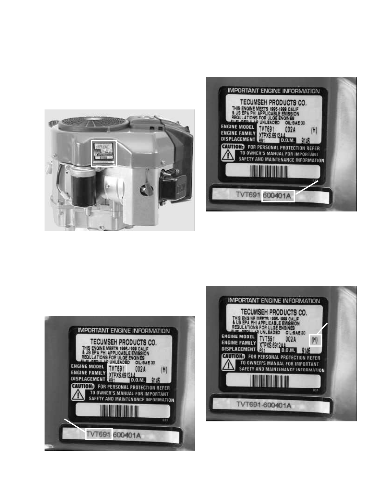
ENGINE IDENTIFICATION
Tecumseh engine model, specification, and date of
manufacture (D.O.M.) are located on decals attached to
the blower housing of the engine. The engine
identification decal also provides the applicable warranty
code, oil and fuel recommendations, EPA (Environmental
Protection Agency) and C.A.R.B. (California Air Resource
Board) Emission Compliance Information. (Illust. 1-1)
The group of numbers following the model number is
the specification number. The last three numbers
indicate a variation to the basic engine specification.
(Illust. 1-3)
SPECIFICATION
NUMBER
1-3
1-1
INTERPRETATION OF ENGINE
IDENTIFICATION
The letter designations (TVT) in a model number
indicate the basic type of engine.
The number designations following the letters (691)
indicate the basic engine model displacement in CC’s
(cubic centimeters). (Illust. 1-2)
ENGINE
MODEL
NUMBER
The letter in parenthesis on the engine information decal
is the warranty code identification number. This letter
designates the length of time the engine is under
warranty. A cross-reference may be found in the service
warranty policy of the master repair manual or the engine
operator’s manual. (Illust. 1-4)
WARRANTY
IDENTIFICATION
NUMBER
1-4
1-2
1-1
Page 7
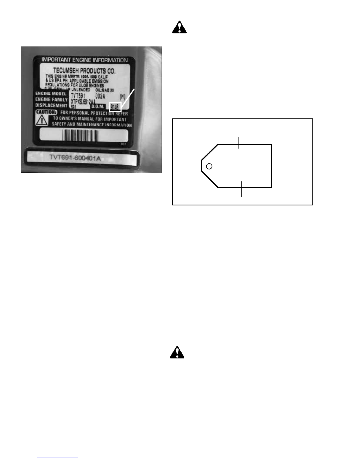
The D.O.M. (date of manufacture) indicates the
production date of the engine by year and numerical day.
(Illust. 1-5)
DATE OF
MANUFACTURE
(D.O.M.)
1-5
This symbol points out important safety
INSTRUCTIONS, WHICH IF NOT FOLLOWED,
could endanger the personal safety of YOU and
others. Follow all instructions.
SHORT BLOCKS
New short blocks are identified by a tag marked S.B.V.
(Short Block Vertical) located on the engine block. When
a short block repair is made, it is vital both the original
engine and short block numbers are present on the
repaired product for correct future parts identification.
(Illust. 1-6)
SBV OR SBH IDENTIFICATION NUMBER
SHORT BLOCK IDENTIFICATION TAG
SBV- 564A
SER 5107
Using model TVT691-600401A D.O.M. 9146 as an
example, the interpretation is as follows:
TVT691- Is the model number.
60041A Represents the specification number used for
properly identifying the parts of the engine.
TVT Tecumseh Vertical Twin.
691 Indicates the displacement in cubic
centimeters.
9146 Is the D.O.M. (Date of Manufacture) formerly
serial number.
9 Is the last digit in the year of manufacture
(1999).
146 Indicates the calendar day of that year (146th
day or May 26th of 1999).
A,B,C A letter following the D.O.M. number
represents the line, shift and plant in which
the engine was built.
Emissionized engines that meet the California Air
Resource Board (C.A.R.B.) or the Environmental
Protection Agency (EPA) standards will include additional
required engine information on the engine decal.
NOTE: To maintain the best possible emission
performance, use only Genuine Tecumseh Parts.
SERIAL NUMBER
1-6
FUELS
Tecumseh Products Company strongly recommends the
use of fresh, clean, unleaded regular gasoline in all
Tecumseh engines. Unleaded gasoline burns cleaner,
extends engine life, and promotes good starting by
reducing the build up of combustion chamber deposits.
Unleaded regular, unleaded premium or reformulated
gasoline containing no more than 10% Ethanol, 15%
MTBE or 15% ETBE may be used.
Leaded fuel is not available in the United States and
should not be used if any of the above options are
available.
Never use gasoline, fuel conditioners, additives or
stabilizers containing methanol, white gas, or fuel blends,
which exceed the limits, specified above for Ethanol,
MTBE, or ETBE because engine/fuel system damage
could result.
CAUTION: THE USE OF SOME ANTI-ICING
ADDITIVES MAY CREATE A METHANOL FUEL
BLEND. DO NOT USE ADDITIVES THAT
CONTAIN METHANOL. FUEL CONDITIONERS
THAT CONTAIN ISOPROPYL ALCOHOL CAN
BE USED IN CORRECT MIXTURE RATIOS.
Regardless of which of the approved fuels are used, fuel
quality is critical to engine performance. Fuel should
not be stored in an engine or container more than 30
days prior to use. Time may be extended with the use of
a fuel stabilizer like TECUMSEH, part number 730245.
See “STORAGE” instructions in this Manual, Operators
Manual, or Bulletin 111.
1-2
Page 8
ENGINE OIL
TECUMSEH FOUR-CYCLE ENGINES REQUIRE THE
USE OF CLEAN, HIGH QUALITY DETERGENT OIL.
Be sure original container is marked: A.P.I. service “SF”
thru “SJ” or “CD”.
TECUMSEH RECOMMENDS USING ONE OF THE
FOLLOWING FOUR CYCLE OILS THAT ARE
SPECIALLY FORMULATED TO TECUMSEH
SPECIFICATIONS.
DO NOT USE SAE 10W40 OIL.
FOR SUMMER (Above 320 F) (0oC) USE SAE 30 OIL.
PART 730225
Use SAE 30 oil in high temperature, high load
applications. Using multigrade oil may increase oil
consumption.
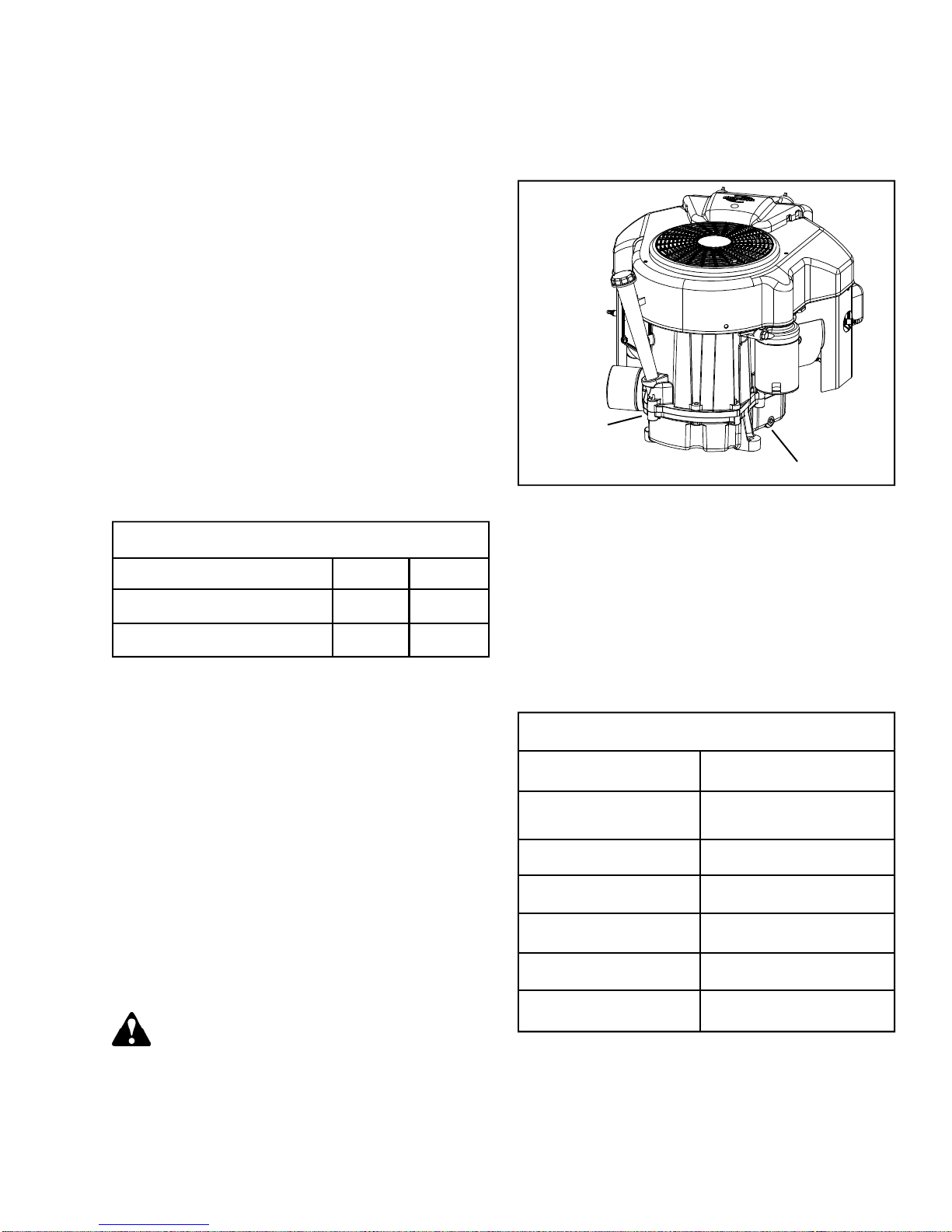
Oil Change Procedure: Locate the oil drain plug in the
mounting flange. The drain plug or cap on most units is
located above the frame in one of the locations shown.
(Illust. 1-7) The oil filter if equipped, can be removed
with a commercially available filter wrench.
FOR WINTER (Below 320F) (0oC) USE SAE 5W30 OIL.
PART 730226
(SAE 10W is an acceptable substitute.)
(BELOW 00F (-18oC) ONLY): SAE 0W30 is an
acceptable substitute.
Oil Capacity
Engine Model oz. ml.
TVT691 with Filter 80 2366
TVT691 Oil Only 72 2129
Change oil and filter after the first two operating hours.
Standard oil change intervals are every 50 hours. Oil
filter changes are recommended every 100 operating
hours.
Oil Change Intervals: Change the oil and filter after
the first 2 hours of operation. Thereafter oil change
intervals are every 50 hours. Oil and oil filter changes
are requested every 100 operating hours. Service should
be performed more often if operated under extremely
dusty or dirty conditions. The oil and filter (if equipped)
should be changed yearly if operated less than 100 hours.
Oil Check: Check the oil each time the equipment is
used or every five-(5) hours of operation. Position the
equipment so the engine is level when checking the oil
level.
CAUTION: A TWIN CYLINDER ENGINE MAY
START AND RUN ON ONLY ONE CYLINDER.
ALWAYS DISCONNECT BOTH SPARK PLUG
WIRES FROM THE SPARK PLUGS AND
GROUND TO THE DEDICATED RETAINING
POSTS LOCATED ON THE VALVE COVER
BOXES BEFORE ATTEMPTING ANY SERVICE
OR MAINTENANCE WORK ON THE ENGINE OR
EQUIPMENT.
ALTERNATE
LOCATION
STANDARD OIL DRAIN PLUG LOCATION
NOTE: An oil change is best performed after the engine
is warm.
Remove the oil plug or cap and allow the oil to drain into
a proper receptacle. Always make sure that drain oil and
filter are disposed of properly. Contact your local
governing authorities to find a waste oil disposal site.
Once the oil is drained, reinstall the drain plug and fill the
engine with new oil to the proper capacity.
1-7
BASIC MAINTENANCE CHART
Pre-filter (Dry Poly) Clean every 25 hours
Air filter (Paper Element) Replace every 100 hours of
operation
Oil change Every 50 hours or annually
Oil filter Every 100 hours or
annually
Spark plug replacement Every 100 hours or
annually
Clean cooling fins Every 200 hours or
annually
Fuel Filter (Replace) Every 100 hours or
annually
1-3
Page 9
BASIC TUNE-UP PROCEDURE:
NOTE: Today’s fuels can cause many problems in an
engines performance due to the fuel quality and short
shelf life (as little as 30 days). Always check fuel as a
primary cause of poor engine performance before
performing any other service.
The following is a minor tune-up procedure. When this
procedure is completed, the engine should operate
properly. Further repairs may be necessary if the engine’s
performance remains poor.
CAUTION: REMOVE THE SPARK PLUG WIRES
AND ATTACH TO THE DEDICA TED RET AINING
POSTS BEFORE DOING ANY SERVICE WORK
ON THE ENGINE.
1. Service or replace the air cleaner. See Chapter 2
under “Service”.
2. Inspect the level and condition of the oil, change or
add oil as required.
3. Remove the blower housing and clean all dirt, grass
or debris from the intake screen, Cylinder head,
cooling fins, carburetor, governor levers and linkage.
4. Check that the fuel filter, fuel tank, and fuel line are
clean. We recommend replacing the fuel filter every
100 hours or annually.
5. Replace the spark plugs every 100 hours or annually,
consult the parts breakdown for the correct spark
plug to be used. Set the spark plug gap (.030") (.762
mm) and install the plug, being careful not to cross
thread. Tighten the spark plug to 21 foot pounds
(28 Nm) of torque. If a torque wrench is not
available, turn the spark plug in as far as possible
by hand, then use a spark plug wrench to turn the
plug 1/2 turn further. If installing a used plug, only
1/8 to 1/4 turn after seat is needed. Note: The correct
plug reach must be used see (Illust. 1-8).
6. Make sure all ignition wires are free of abrasions or
breaks and are properly routed so they will not rub
on the flywheel.
7. Completely clean the cooling fins, intake screen and
linkages of all dirt and debris. Reinstall the blower
housing, fuel tank, fuel line, and air cleaner assembly
if removed. Be careful not to pinch any of the
wires upon re-assembly.
8. Make sure all remote cables are correctly routed and
adjusted for proper operation. See Chapter 4, under
“Speed Controls and Linkage”.
9. Reinstall the spark plug wires, add fuel and oil as
necessary, start the engine.
STORAGE
(IF THE ENGINE IS TO BE UNUSED FOR 30 DAYS
OR MORE)
CAUTION: NEVER STORE THE ENGINE WITH
FUEL IN THE TANK INDOORS OR IN
ENCLOSED, POORLY VENTILATED AREAS,
WHERE FUEL FUMES MAY REACH AN OPEN
FLAME, SPARK OR PILOT LIGHT AS ON A
FURNACE, WATER HEATER, CLOTHES
DRYER OR OTHER GAS APPLIANCE.
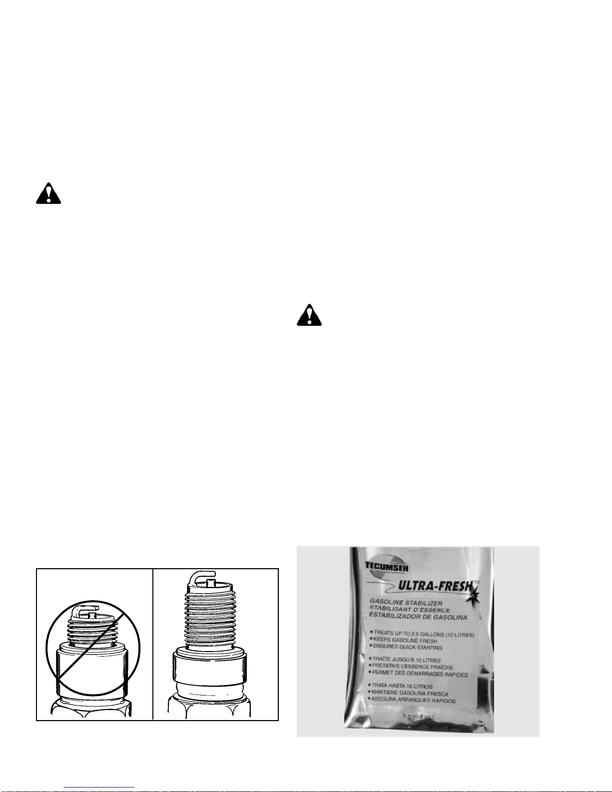
Gasoline can become stale in less than 30 days and
form deposits that can impede proper fuel flow and engine
operation. To prevent deposits from forming, all gasoline
must be removed from the fuel tank and the carburetor.
An acceptable alternative to removing all gasoline, is by
adding Tecumseh fuel stabilizer, part number 730245,
to the gasoline. Fuel stabilizer is added to the fuel tank
or storage container. Always follow the mix ratio found
on the stabilizer container. Run the engine at least 10
minutes after adding the fuel stabilizer to allow it to
reach the carburetor. (Illust. 1-9)
STANDARD
PLUG
1-4
OHV
1-8
1-9
Page 10
CHAPTER 2. AIR CLEANERS
GENERAL INFORMATION
The air cleaner is the device used to eliminate dust and
dirt from the air supply. Filtered air is necessary to assure
that abrasive particles are removed before entering the
combustion chamber. Dirt allowed into the engine will
quickly wear the internal components and shorten engine
life.
The TVT series engine uses a paper-type air filter system
and also has a dry foam pre-filter.
Extremely dirty conditions require more frequent pre-filter
cleaning or paper element replacement.
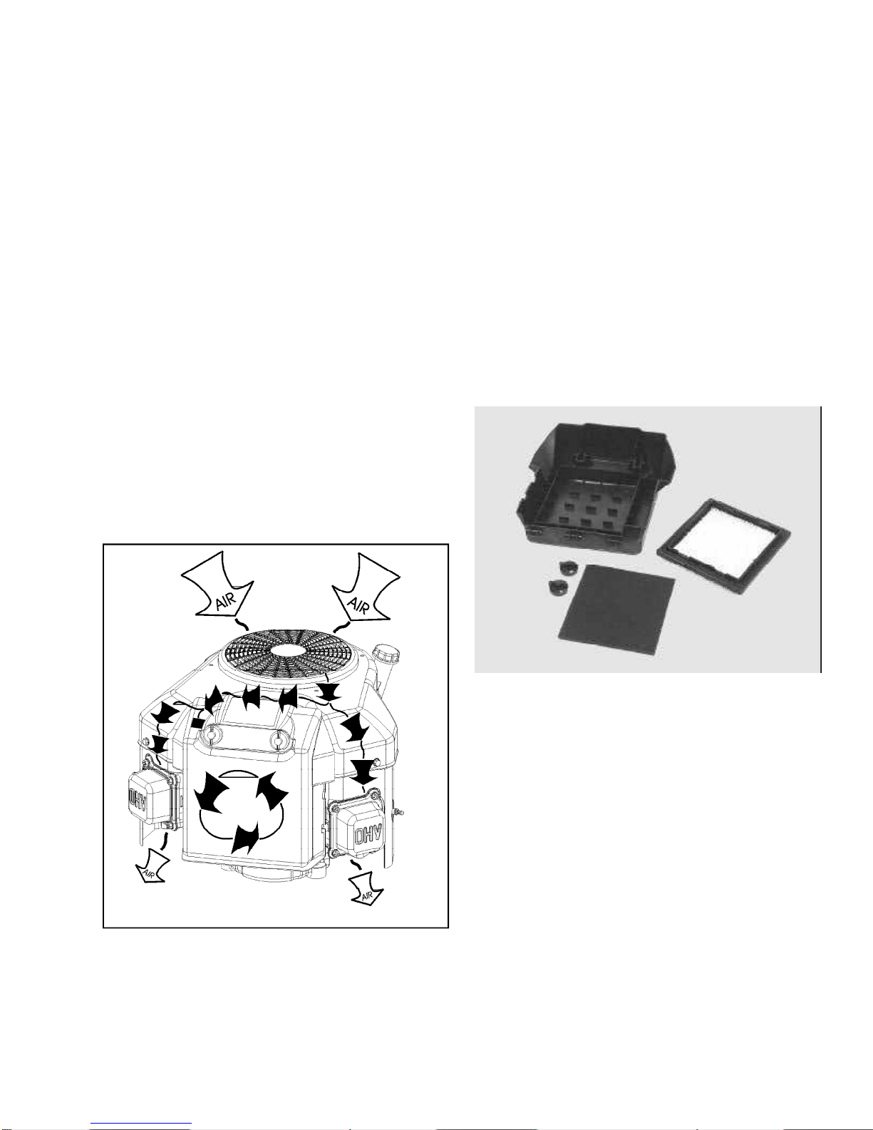
OPERATION
The air filter cover secures and seals the paper filter
element in place. The cover also prevents large particles
from entering the filter body and completes the KleenAire® circuit. The air is first filtered through the flywheel
and blower housing then enters the air filter cover. It
travels through the pre-filter then the paper filter element.
Pre-filters typically extend the paper filter life.
(Illust. 2-1)
COMPONENTS
The cover holds the poly pre-cleaner and clamps the
paper filter in place, creating a dirt tight seal. The cover
also prevents large debris from entering the filter body.
The pre-cleaner is made of a polyurethane foam and
designed to pre-filter the air prior to it passing through
the paper filter. This added stage, assures the operator
of maximum air filtering and extends paper filter life.
The paper filter element is the main filter to stop
impurities from entering the engine. This dry-type element
is pleated paper for increased surface area maximizing
its life. The filter has rubberized edges to assure sealing.
(Illust. 2-2)
2-1
2-2
TROUBLESHOOTING AND TESTING
If the engine’s performance is unsatisfactory (runs
unevenly, starts smoking abnormally or loses power),
the first engine component(s) to be checked are the air
filter(s). A dirt restricted or oil soaked filter will cause
noticeable performance problems. Polyurethane pre-filter
can be cleaned following the service procedure listed
under “Service” in this chapter. A paper-type air filter can
only be replaced NEVER attempt to clean a paper filter.
The paper-type filter must not have any oil film or residue
present. Should the paper have a brown tint it may have
been damaged by an excessively oiled pre-filter or
crankcase breather problems. Follow the procedure listed
in the “Service” section of this chapter for filter
replacement or cleaning.
2-1
Page 11

SERVICE
Cleaning of the polyurethane pre-filter element is
recommended every twenty-five (25) operating hours or
(3) months, whichever comes first. Extremely dirty or
dusty conditions may require daily cleanings.
2. Remove the paper filter. Note: Paper filters must be
replaced NEVER attempt to clean a paper filter.
3. Remove the polyurethane pre-cleaner from the
cover.
NOTE: Do not oil the pre-filter, paper element damage
can occur.
The paper filter element should be replaced once a year
or every 100 operating hours, more often if used in
extremely dusty conditions.
NOTE: Never run the engine without the complete air
cleaner assembly installed on the engine. Always replace
the filter element with a Tecumseh original replacement
part to maintain proper filtration, emissions compliance
and long engine life.
Disassembly Procedure
1. Remove the wing nuts holding the air cleaner cover
in place. Swing the cover out, then lift to remove.
(Illust. 2-3)
BODY
(ATTACHED TO ENGINE)
PAPER FILTER
FOAM PRE-FILTER
WING NUTS (2)
4. Wipe or wash out the air filter cover and base. (Illust.
2-4)
2-4
5. Service the polyurethane pre-filter element by
washing in liquid dish soap and warm water until
clean. Squeeze out the excess water (Never Twist).
Finish drying the element by squeezing it in a dry
cloth or paper towel.
SLOTS
TABS
COVER
2-3
NOTE: DO NOT OIL THE PRE-FILTER IT MUST
BE INSTALLED DRY TO PREVENT SATURATION
OF THE PAPER FILTER ELEMENT.
6. Install the pre-cleaner and new air filter in the cover.
Replace the filter cover and tighten the wing nuts,
be careful not to over-tighten it. Note: The air filter
system on all models can be upgraded to include
the pre-cleaner if the OEM did not originally request
one.
2-2
Page 12

CHAPTER 3. CARBURETORS AND FUEL SYSTEMS
GENERAL INFORMATION
The TVT engine uses two series seven (7) float type
carburetors. This carburetor uses a choke enrichment
system to provide easy cold engine starting. To comply
with emission standards, the carburetor idle and highspeed fuel mixtures are non-adjustable. Carburetor
cleaning and related fuel system service is covered in
this chapter.
FLOAT STYLE CARBURETORS
A float is used to maintain the operating level of fuel in
the carburetor bowl. As the engine consumes fuel, the
fuel level in the carburetor bowl drops and the float moves
downward. This allows the inlet needle valve to move off
the sealing seat, and fuel to enter the carburetor float
bowl. As the fuel level in the bowl rises, it elevates the
float. This upward float motion moves the inlet needle
valve to the closed position. When the needle contacts
the seat, the fuel flow is stopped. The tapered end of the
inlet needle varies the fuel flow rate keeping the supply
constant. (Illust. 3-1) The float height on the series 7
carburetor is fixed and may not be adjusted.
OPERATIONAL CIRCUITS SERIES 7
CARBURETOR
SERIES 7
IDLE
PRIMARY
IDLE MIXING
WELL
IDLE
RESTRICTOR
IDLE/TRANSFER
FUEL
PASSAGE
IDLE PROGRESSION HOLES
IDLE
AIR BLEED
SPRING
MAIN JET
ATMOSPHERIC
VENT PASSAGES
MAIN NOZZLE
AIR BLEED
3-2
INLET
NEEDLE
3-1
NOTE: Gravity fed systems must have the bottom of
the fuel tank no lower than the fuel inlet of the carburetor.
When servicing carburetors, use the engine model and
specification number to obtain the correct carburetor part
number or parts. An alternate method is to use the
manufacturing number stamped on the carburetor.
Convert this number to a service part number in Div. 5
carburetor section of the Master Parts Manual. This
method can also be used in microfiche and computer
parts look-up systems.
Choke Circuit: In the “CHOKE”/“START” position, the
choke shutter is closed, and the only air entering the
engine, enters through openings around the shutter. As
the starting device cranks the engine over, the pistons
travel downward on the intake stroke, creating a lowpressure area in the cylinder. High-pressure
(atmospheric) air rushes into the cylinder to fill the lowpressure area created.
Since the choke shutter blocks the majority of the air
passage, a relatively small quantity of air enters the
carburetor. The main nozzle and idle fuel discharge ports
are all supplying fuel at this point. This is due to the
increased low air pressure in the intake system of the
engine. A maximum fuel flow through the carburetor
orifices combined with the reduced quantity of air that
passes through the carburetor, creates a very rich fuel
mixture needed to start a cold engine.
3-1
Page 13
Governed Idle Circuit: The TVT series engine uses a
governed idle system. In the low speed throttle position,
engine speed is being maintained by the governor NOT
the idle speed adjustment screw. The governed idle
system improves throttle response when the engine load
changes. The relatively small amount of fuel/air mixture
is supplied through the primary idle orifice location under
the idle mixing well welch plug. (Illust. 3-3)
IDLE SPEED
ADJUSTMENT
IDLE
MIXING
WELL
SCREW
3-3
True Idle: The idle speed adjustment screw on governed
idle engines perform as a stop to prevent complete
closure of the throttle plate. This partial open throttle
position is required for good starting performance. The
idle adjustment screw is set 600 RPM lower than the
governed idle speed. (Found on microfiche card #30 or
the computer parts look-up systems.) See governed
speed adjustment procedure Chapter 4.
CAUTION: DUAL CARBURETORS MUST BE
PROPERLY SYCRONIZED. DO NOT ADJUST
IDLE SPEED SCREW WITHOUT PROPER
SYNCHRONIZATION.
Transfer/Intermediate Circuit: During Intermediate
engine operation or light loads, additional orifices are
uncovered in the idle mixing well, as the throttle shutter
opens. The fuel being released from these jets is already
pre-mixed (atomized) with air prior to entering the air
stream in the venturi of the carburetor. When the fuel
enters the air stream it further mixes with the air which
maximizes combustibility.
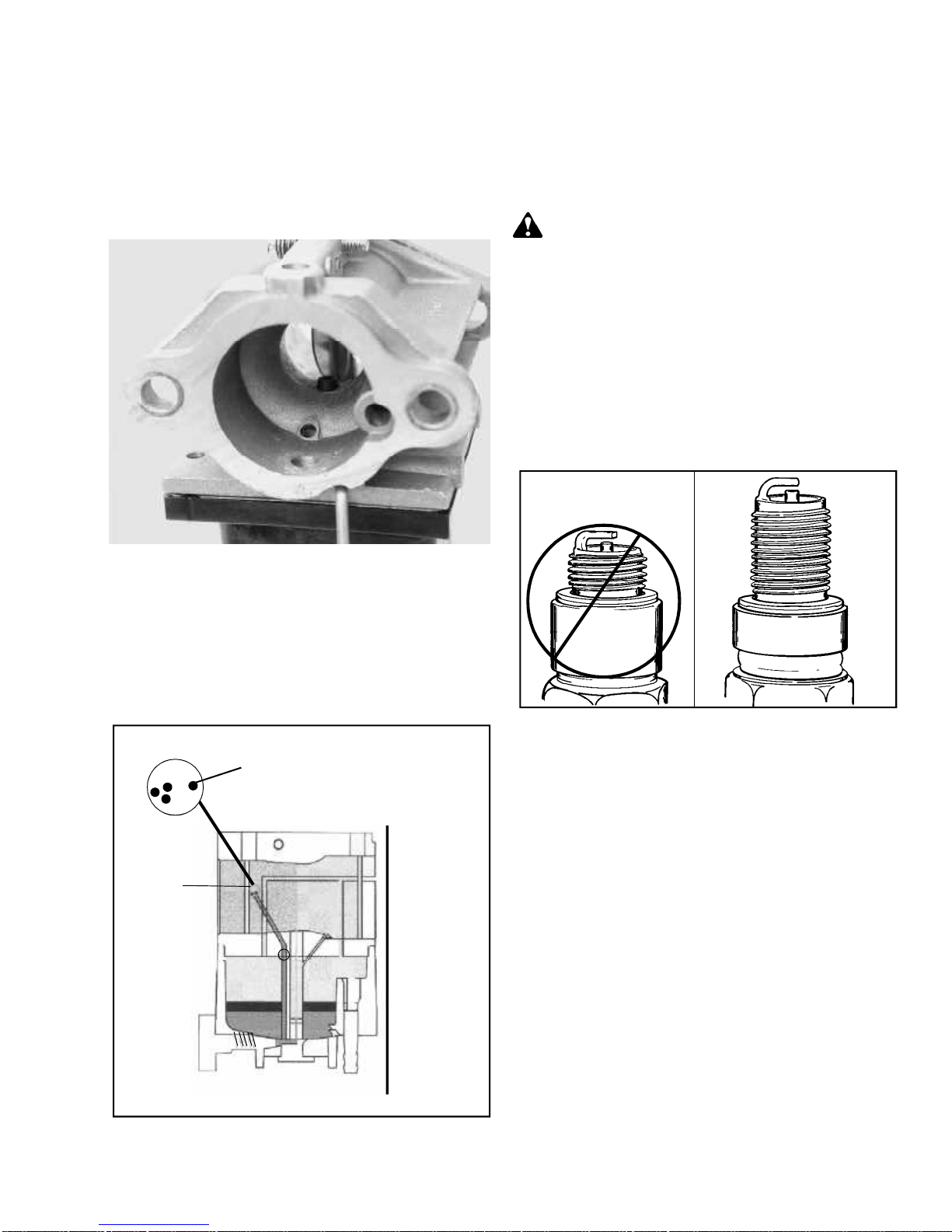
Idle Mixing Well: The idle mixing well of the carburetor
contains a series of metering holes. These metering holes
are the primary and secondary idle circuit as well as the
idle air bleed hole. Proper servicing of the carburetor
requires removal of the welch plug and cleaning of these
metering holes. (Illust. 3-4)
IDLE
MIXING WELL
IDLE SPEED
ADJUSTMENT
SCREW
3-4
High Speed Circuit: During HIGH-SPEED engine
operation, the throttle shutter is opened beyond the idle/
transfer discharge ports. Air is flowing through the
carburetor(s) at a high rate. The venturi, which decreases
the size of the air passage through the carburetor, causes
the airflow to further accelerate. This rapidly moving air
creates a low-pressure area at the main nozzle (Emulsion
Tube) discharge opening.
Using air that is channeled to the emulsion tube through
the main nozzle air bleed, a mixture of fuel and air is
drawn up the emulsion tube.
The addition of air creates an atomized mixture before
being discharged into the venturi. Fuel flow is created
by the difference in the atmospheric air pressure on the
fuel in the carburetor bowl and the main nozzle opening.
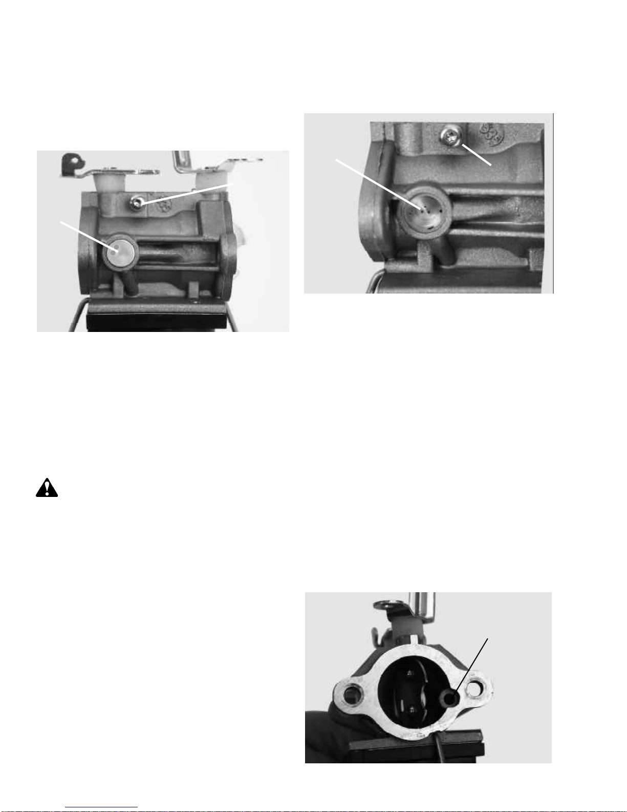
Atmospheric Vent: For the fuel to flow out of the
carburetor, the bowl must be vented to atmospheric
pressure. The internal vent is located at the 4 o’clock
position from the choke end of the carburetor. (Illust.
3-5) This passage should be checked for blockage if
engine performance is in question.
ATMOSPHERIC
VENT
3-2
3-5
Page 14
Main Nozzle Air Bleed: Air is bled into the main nozzle
through the main nozzle air bleed passage located in
the 6 o’clock position of the carburetor’s choke end. (Illust.
3-6) This passage allows air to mix with the fuel traveling
up the main nozzle creating a pre-atomized mixture. The
fuel is then released into the venturi from the nozzle tip.
Atomization occurs as the fuel mixture contacts the fast
moving air stream in the venturi and flows into the intake
of the engine.
TESTING
1. Should repeated efforts to start the engine using the
procedure listed in the operator’s manual fail, check
for spark by removing the high-tension lead. Install
an ignition tester and check for spark. If the spark is
bright blue and consistent, proceed to step 2. If no
or irregular spark see Chapter 6 under “Testing”.
CAUTION: KEEP ALL COMBUSTIVE SOURCES
AWAY. AVOID THE SPRAY FROM THE SPARK
PLUG HOLE WHEN CRANKING THE ENGINE
OVER AND MAKE SURE THE PLUG WIRES ARE
PROPERLY GROUNDED TO THE DEDICATED
RETAINING POSTS.
2. Remove and visually inspect the condition of each
spark plug, a wet condition indicates the presence
of gasoline in the cylinder. Although this indicates
fuel is present the fuel condition regarding its
combustibility should always be checked.
NOTE: Check plug for correct reach. (Illust. 3-8)
3-6
Low Speed Idle Air Bleed: The low speed circuit of the
carburetor has an idle air bleed passage which performs
the same function as the high-speed air bleed. It premixes fuel and air prior to entering the throat of the
carburetor. This passage is located in the idle mixing
well (Illust. 3-7)
LOW SPEED
IDLE AIR BLEED
IDLE MIXING
WELL
PLUG
OHVSTANDARD
3-8
3. If either spark plug is dry, check for restrictions in
the fuel system, which supplies that cylinder. If both
plugs are dry check the fuel supply system and
continue with step #4. If the spark plug is wet,
continue with step # 8.
4. Dry Spark Plug: Begin by checking the fuel cap for
proper atmospheric venting. With the fuel cap in place
and tightened, remove the fuel line prior to the pump
allowing fuel to flow into a proper receptacle. Allow
at least 1 gallon of fuel to flow out, noting the rate of
flow. If it remains consistent the vent is performing
properly. Re-connect the fuel line(s) to the pump.
3-7
NOTE: Today’s fuels can cause many problems in
engine performance due to the fuels quality and short
shelf life. Always check fuel as a primary cause of
engine poor performance.
5. Remove the air filter, visually check the choke
shutter(s) operation for complete closure when the
throttle or independent choke control are in the full
choke position.
3-3
Page 15

6. Fuel Supply If the fuel flow to the carburetors is
adequate and no fuel is evident at either spark plug,
the carburetor bowl(s) will need to be removed for
service. See “Service” in this chapter or consult the
“Carburetor Troubleshooting” chart to diagnose
carburetor symptoms. Improper fuel flow indicates
the fuel, fuel line, filter or tank require cleaning or
replacement.
7. Compression Test Most Tecumseh engines include
a compression relief system. These systems make
publishing compression values impractical. However,
following is a cylinder compression balance test,
which can be preformed to help diagnose a possible
compression concern.
1. Remove air filter cover, air filter and both spark
plugs
2. Ground out the spark plug wires to the engine.
3. Install a compression tester into either of the
spark plug holes of the cylinder head.
8. Wet Plug(s) A wet spark plug indicates fuel is being
supplied by the carburetor. A restricted air filter,
carbon shorted or defective spark plug, excessive
choking or a defective carburetor, may have flooded
the engine. With the spark plug(s) removed and the
plug wire(s) grounded to the dedicated retaining
posts, place a shop towel over the spark plug hole.
Turn the engine over very slowly by hand to remove
excess gasoline from the engine cylinder.
CAUTION: KEEP ALL COMBUSTIVE SOURCES
AWAY. AVOID THE SPRAY FROM THE SPARK
PLUG HOLE WHEN CRANKING THE ENGINE
OVER AND MAKE SURE THE PLUG WIRES
ARE PROPERLY GROUNDED TO THE
DEDICATED RETAINING POST.
9. Replace the air filter if restricted or oil soaked, if the
paper filter has a brown color it may have been
damaged by oil and should be replaced. Replace
the spark plug if questionable then install the spark
plugs and high tension leads. Attempt to start the
engine.
4. Turn engine over until the highest reading is
recorded on the compression tester.
5. Write down the reading, remove the compression
tester install it into the remaining cylinder head
and repeat.
Compare the two readings. The difference between
the two cylinders should not exceed 20%. Example:
Cyl #1 90 PSI, Cyl #2 75 PSI. There is 15-PSI
difference between cylinders. Divide this number (15)
into the highest compression reading (90) giving a
17% difference between cylinders. A difference
above 20% or an extremely low compression reading
(below 50 PSI) will require further leak testing or
cylinder head removal for inspection.
Cylinder #1 Cylinder #2 Difference %
90 psi - 75 psi = 15 psi ÷ 90 = 17%
10. If the engine floods and fails to start, the carburetor(s)
will require service. See the “Carburetor
Troubleshooting” chart for additional causes. If the
carburetor is functioning properly the problem may
be ignition or timing related. Reference
“Troubleshooting” under “Ignition” for further
assistance.
3-4
Page 16
CARBURETOR DISASSEMBLY
PROCEDURE
Before performing any carburetor service check the
throttle/choke control(s) for proper adjustments. Make
sure the unit is reaching full choke shutter position on
both carburetors.
NOTE : The series seven carburetor uses FIXED IDLE
AND MAIN JETS AND SHOULD BE SERVICED ONLY
BY QUALIFIED TECHNICIANS TO PREVENT
DAMAGE. It is a violation of both the U.S. EPA and CARB
regulations to modify the carburetor from the original
factory jetting unless specifically authorized.
CAUTION: DRAIN THE FUEL INTO AN
APPROVED CONTAINER OUTDOORS, AND
AWAY FROM ANY OPEN FLAME OR
COMBUSTION SOURCE. BE SURE THE ENGINE
IS COOL.
1. Remove the fuel line. Use care not to damage the
float bowl or retainer. Disconnect the wires from the
fuel shut-off solenoids. Release the float bowl retainer
bail. The float bowl assembly may now be removed
by pulling straight down. (Illust. 3-9)
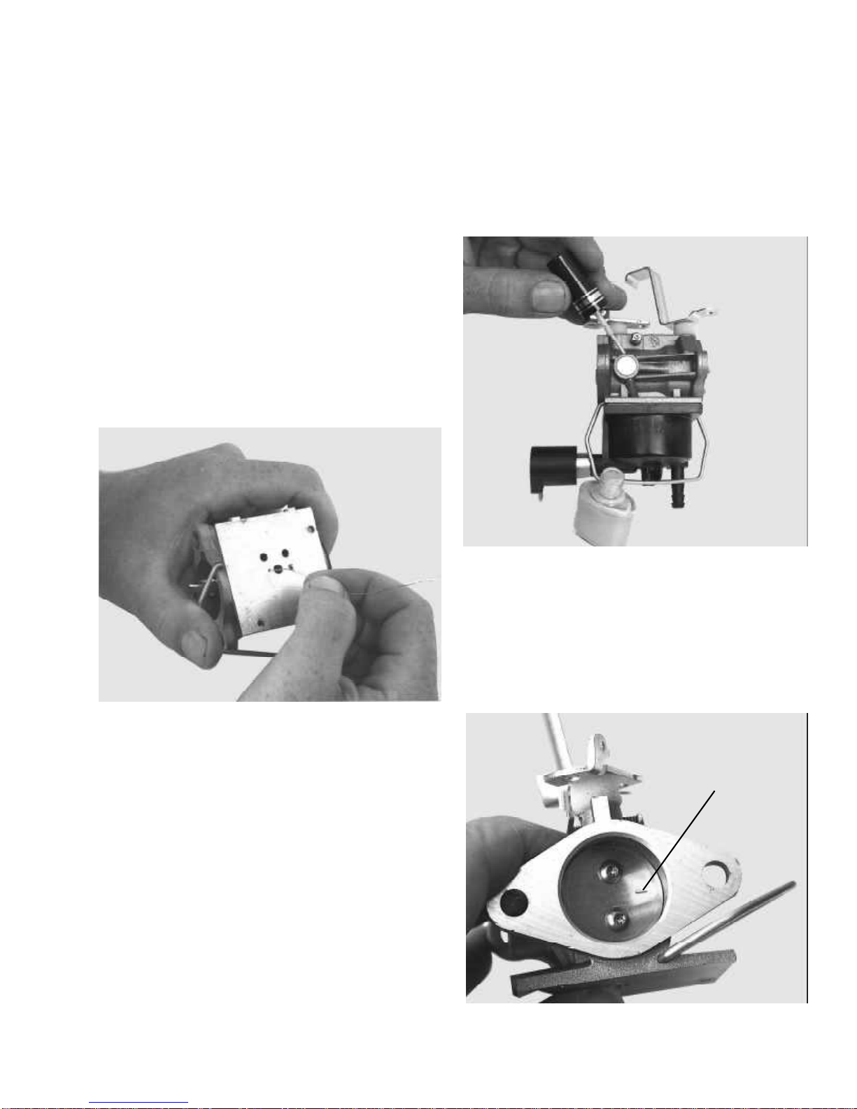
2. Remove the main nozzle (Emulsion) tube, “O” ring,
and spring located in the center leg of the float bowl.
(Illust. 3-10)
SPRING
O-RING
MAIN NOZZLE
(EMULSION TUBE)
3-10
3. Next remove the bowl drain screw or fuel shut off
solenoid and gasket. Remove the spring, metering
jet, and “O” ring. (Illust. 3-11)
SOLENOID
GASKET
METERING
JET
3-9
SPRING
O-RING
3-11
4. Float removal is done by grasping the cross-brace
on the float with needle nose pliers. Then pulling in a
horizontal motion to release the float assembly. (Illust.
3-12) Removal by any other method may cause
damage.
3-12
3-5
Page 17
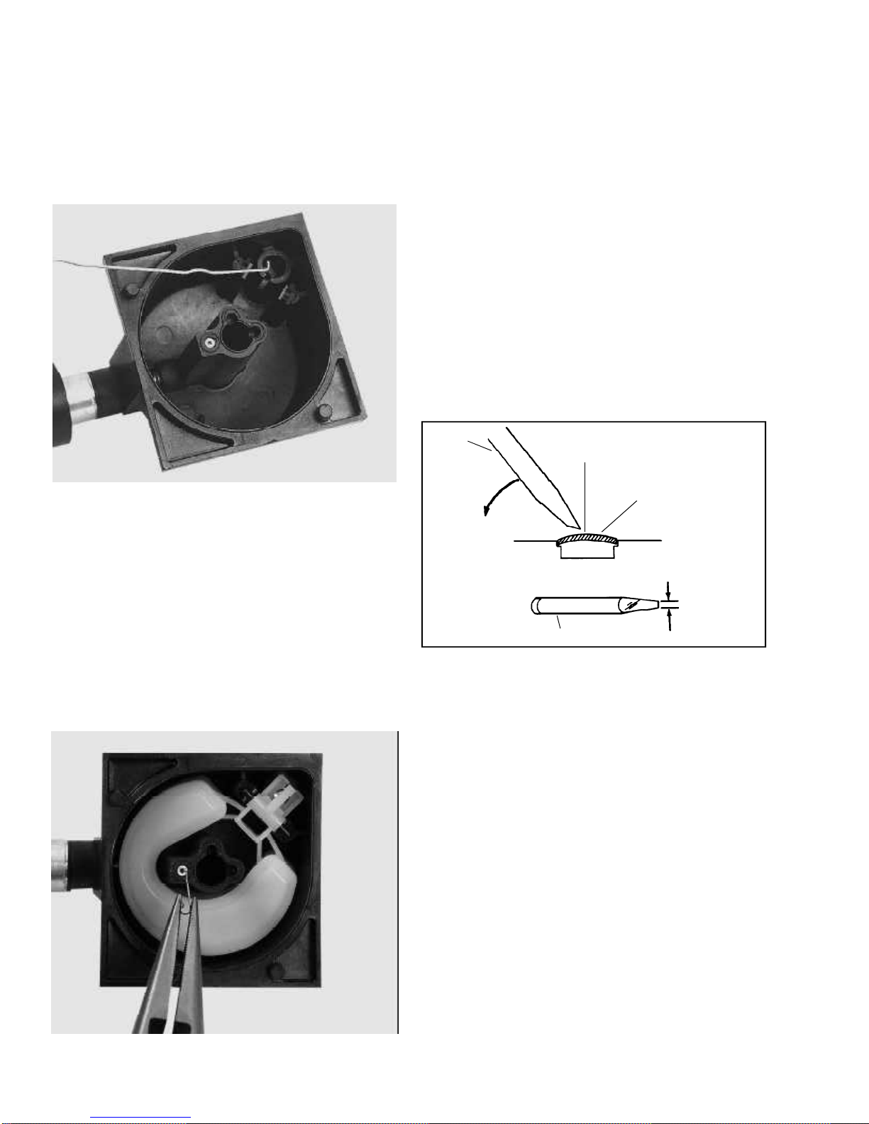
5. Remove the inlet needle seat using a No. 4 crochet
hook or a paper clip with a 3/32" (2.38 mm) hook
end. Push the hook through the hole in the center of
the seat and pull out to remove it. NOTE: A metal
retaining ring may be present on top of the seat to
aid in its retention, this will come out with the seat. If
a ring is present or comes with the new seat reinstall
it. (Illust. 3-13)
NOTE: Before removing the main carburetor body,
mark or sketch the choke and throttle linkage
connection points. Also MARK THE EDGES OF THE
THROTTLE AND CHOKE SHUTTERS. THE
SHUTTERS HAVE BEVELED EDGES AND MUST
BE INSTALLED IN THE ORIGINAL POSITION.
7. Use a Torx T-10 to remove the choke and throttle
shutters. Remove the throttle shaft, choke shaft and
return springs.
8. Welch plug Removal: Secure the carburetor in a vise
equipped with protective jaws. Use a small chisel
sharpened to a 1/8" (3.175 mm) wide wedge point .
Drive the chisel into the plug to pierce the metal and
push down on the chisel prying the plug out of the
hole. (Illust. 3-15)
NOTE: Be careful not to drive the chisel through the
plug damaging the metering holes underneath.
3-13
6. Idle Restrictor: The idle restrictor is located to the
side of the center leg in the fuel bowl. (Illust. 3-14)
Clean the passage using a piece of wire (maximum
.015, .0006 mm), carburetor spray and compressed
air, verify it is open. If the restrictor remains plugged
it can be serviced by replacement of the float bowl
assembly only.
NOTE: New service fuel bowls come with the
restrictor installed.
SMALL
CHISEL
PRY OUT
PLUG
DO NOT ALLOW
CHISEL POINT
TO STRIKE
CARBURETOR
BODY OR
CHANNEL
REDUCER
PIERCE PLUG
WITH TIP
SMALL CHISEL
WELCH PLUG TO
BE REMOVED
ABOUT 1/8”
(3.175 mm)
WIDE
3-15
3-6
3-14
Page 18
INSPECTION
After careful disassembly of the carburetor, clean the
carburetor body and float bowl with solvent, or spray
carburetor cleaner. Wearing eye protection, use
compressed air and soft tag wire to clean internal
carburetor passages. (Illust. 3-16) Examine the float for
cracks or leaks. Check the float hinge bearing surfaces
for wear, as well as the tab that contacts the inlet needle.
Examine the throttle, choke shaft, and carburetor body
at the bearing points and holes into which the linkage is
fastened. If dust seals are present, check the seal
condition and for correct placement next to the carburetor
body. If the condition of any of these parts is worn or
questionable replace them. The float can be checked
for leakage by submersion in a clear jar filled with hot
water. If any air bubbles are noted the float must be
replaced.
NOTE: DO NOT INTERCHANGE MAIN NOZZLES OR
METERING JETS FROM OTHER CARBURETORS.
CARBURETOR RE-ASSEMBLY
WELCH PLUGS
To install a new welch plug, secure the carburetor in a
vise equipped with protective jaws. Place the welch plug
into the mixing well pocket with the raised portion up.
With a punch equal to the size of the plug-hole, flatten
the plug. Do not dent or drive the center of the plug below
the top surface of the carburetor. After installation of the
welch plug, seal the outer diameter with fingernail polish.
(Illust. 3-17)
3-16
3-17
THROTTLE SHAFT AND PLATE
When reassembling the throttle plate on a series 7
carburetor, it is important that the marking on the plate
be in the 3 o’clock position facing out with the throttle
plate closed. (Illust. 3-18)
3 O’CLOCK
POSITION
3-18
3-7
Page 19
CHOKE SHAFT AND PLATE
Install the choke return spring on the choke shaft with
the squared end up and hooked into the notch on the
arm. Work the dust shield up around the spring and insert
the choke shaft into the carburetor body. Rotate the shaft
counterclockwise until the tang on the spring rests against
the left side center boss on the carburetor body. (Illust.
3-19)
FUEL BOWL ASSEMBLY
Inlet Needle & Seat
When servicing the fuel bowl assembly, a new needle
and seat should always be installed to reduce the
possibility of leakage.
Make sure the seat cavity is clean. Moisten the seat
with oil and insert the seat with the grooved side down
and away from the inlet needle. Press the seat into the
cavity using a 5/32” (3.969 mm) an Allen wrench or a
flat punch, making sure it is firmly seated. (Illust. 3-20) If
the new needle and seat contains a retainer install it on
top and in contact with the seat.
3-19
Always use new shutter screws part 650506 when
reinstalling a shutter plate. Install the screws so they
are slightly loose. Apply light downward pressure on the
shaft and rotate it clockwise to seat the shutter in the
bore, then tighten the shutter screws. Check for binding
by rotating the shaft. If necessary, adjust the shutter by
loosening and repositioning, then retighten the screws.
3-20
Main Jet Assembly
Install a new O-ring in the main jet cavity (verify the
original o-ring has been removed). Place the spring over
the shoulder of the main jet and insert into the cavity
with the main jet towards the o-ring. Next install a new
fiber gasket on the bowl drain screw or fuel shut-off
solenoid and tighten to 25-30 In. lbs. (2.83 - 3.4 Nm).
(Illust. 3-21)
SOLENOID
GASKET
METERING
JET
3-8
SPRING
O-RING
3-21
Page 20
Main Nozzle (Emulsion Tube)
Place the main nozzle tension spring into the cavity of
the float bowl. Apply a small amount of oil to the o-ring
on the main nozzle and insert it into the float bowl cavity.
Float Installation
Install the float with a new inlet needle and float hinge
pin onto the float bowl assembly. Carefully push the hinge
pin into the retaining post using a small flat blade
screwdriver. Check the float movement for complete
travel.
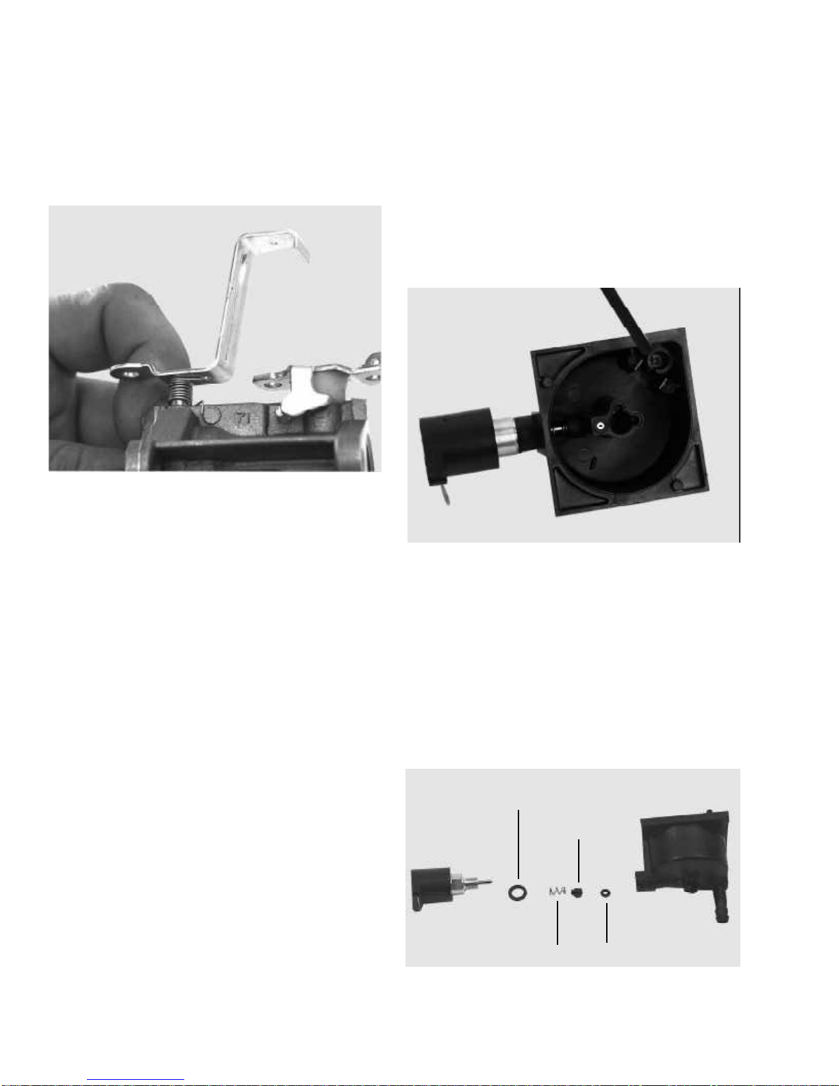
IMPULSE FUEL PUMPS
11
1
10
4
7
NOTE: EMISSIONIZED ENGINES OPERATED WITHIN
THE UNITED STATES MAY HAVE HIGH ATTITUDE
JETS AVAILABLE, CONSULT SERVICE BULLETIN
110 FOR INFORMATION.
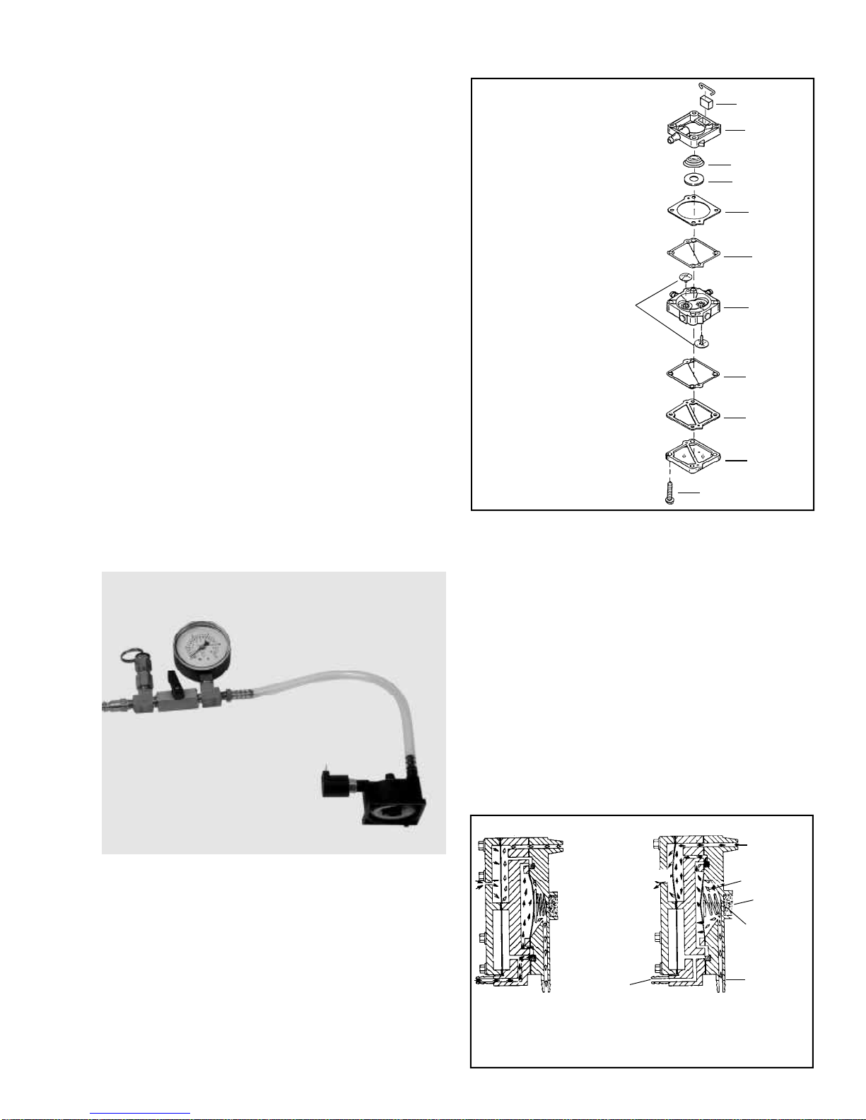
Final Checks
Test the inlet needle and seat sealing using Tecumseh
service kit 670340 or a similar pop-off tester. To test the
pop off pressure remove the float bowl, float and inlet
needle. Place a drop of fuel on the seat and reinstall the
needle and float. Hook up the pressure tester and apply
approximately 6-9 PSI of pressure or until the needle
pops off the seat. Slowly release the pressure to not
less than 1 ½ PSI. The needle should seat between
1 ½ - 6 PSI for a minimum of five minutes. If the minimum
1 ½ PSI cannot be maintained the needle and seat will
need to be serviced. (Illust. 3-22)
11
5
1 - Body, Impulse
2 - Body, Pump
3 - Cover, Pump
4 - Bearing, Spring
5 - *Valve, Check (2)
6 - *Gasket, Pump Cover
7 - *Diaphragm, Pump (2)
9 - Screw, 1-1/4" (4)
10 - *Spring, Pressure
11 - *Filter, Air
9
2
8
6
3
3-23
Impulse fuel pumps are externally mounted in the fuel
circuit between the fuel supply and the carburetor. A fuel
pump must be used if the fuel supply outlet is lower than
the bowl inlet. There MUST be a in-line fuel filter installed
prior to the pump to prevent system damage.
Impulse fuel pumps are operated by positive and
negative pressure pulsation in the crankcase, which are
created by the up, and down movement of the piston. A
hose called a pulse line, connects the fuel pump
diaphragm chamber to the crankcase and transmits the
pulses to the pump diaphragm. These impulses actuate
the diaphragm creating the pumping action to lift the
fuel from the fuel tank to the carburetor(s). (Illust. 3-24)
The pump body contains check valves, which open and
close preventing the fuel from going backwards from
the pump.
Fuel Bowl Retaining Bail
The retainer bail must hold adequate pressure on the
float bowl to prevent air or fuel leakage during operation.
When re-installed, the force should be adequate to
securely clamp the bowl to the body of the carburetor. If
damage occurred upon bowl removal replace the bail.
3-22
VALVE CLOSED
CRANKCASE PRESSURE
ê
ATMOSPHERIC PRESSURE ACTING
á
ON DAMPING DIAPHRAGM
FUEL FLOW
á
ATMOSPHERIC
VENT
FUEL SUPPLY
CRANKCASE SUCTION AND
ê
FLOW DIRECTION
ATMOSPHERIC PRESSURE
ACTING ON DAMPING
á
DIAPHRAGM
CARBURETOR
FITTING
VALVE OPEN
DIAPHRAGM
FILTER
AIR BLEED
VALVE
CLOSED
PULSE LINE
TO CRANKCASE
SUCTION FUEL FLOW
á
DIRECTION
ATMOSPHERIC PRESSURE
ê
CAUSED FUEL FLOW
3-24
3-9
Page 21

Fuel Pump Testing: The maximum lift is 24 inches
(610 mm). A fuel pump may be tested with our leak test
kit part number 670340 or a commercially available low
pressure gauge. Connect the low pressure gauge to the
fuel inlet fitting. Apply no more than 5 PSI (.35 Bar) of
pressure. The air pressure should pass freely through
the pump and out of the fuel outlet fitting. Next, attach
the low pressure gauge to the fuel outlet fitting. Apply
less than 5 PSI (.35 Bar) of pressure. Turn off the air
valve and watch for any pressure drop. The fuel pump
should hold a maximum of 5 PSI (.35 Bar) for one minute.
NOTE: Do not exceed 5 PSI (.35 Bar) of pressure or
fuel pump damage may occur.
CAUTION: DRAIN ALL FUEL INTO AN
APPROVED CONTAINER OUTDOORS, AND
AWAY FROM ANY OPEN FLAME OR
COMBUSTION SOURCE. BE SURE THE
ENGINE IS COOL.
NOTE: A crankcase overfilled with engine oil can affect
pump operation by splashing oil over the pulse line
passage causing erratic pump operation.
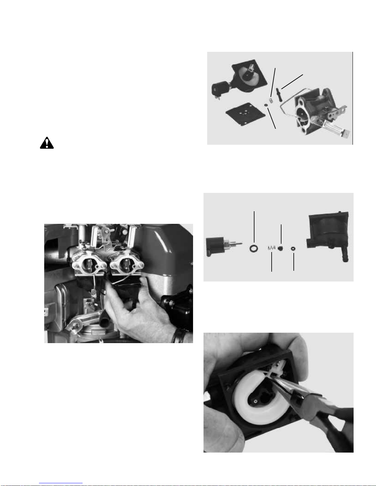
IMPULSE FUEL PUMP SER VICE
The valve type impulse pump can be serviced using the
following procedure.
1. Remove the pump from the engine noting its exact
mounting location and position.
4. Clean the body parts with solvent and blow out all
passages using compressed air.
5. After drying all parts, install the new check valves
with the face of the valve facing the raised portion of
the passage. (Illust. 3-26) After installation, cut off
the extended portion of the check valve stems flush
with the pump body.
3-26
6. Install the diaphragms against the center portion of
the body with the gaskets against the outside covers.
The parts can only be assembled one way without
damage.
2. Note or mark the pump body alignment by lightly
scribing lines at various mating joints. Remove the
four screws and disassemble the pump.
(Illust. 3-25)
3-25
3. Remove the gaskets, diaphragms, check valves,
springs and air filter. (If equipped).
7. Install the spring bearing on the new spring and place
into position. (Illust. 3-27)
8. Assemble the body sections, install the retaining
screws, and torque the screws to 12 - 16 inch
pounds (1.36 - 1.81 Nm).
9. Install new filter in pump cavity if present.
3-27
NOTE: Retain the spring bearing. A replacement is
not supplied in the fuel pump kit.
3-10
Page 22

CHAPTER 4. GOVERNORS AND LINKAGE
GENERAL INFORMATION
The TVT engine is equipped with an internal mechanical
governor. The governor’s function is to maintain a R.P.M.
setting when engine loads are added or taken away. This
chapter includes governor assembly linkage illustrations
to aid in governor or speed control assembly.
OPERATION
As the speed of the engine increases, the weights on
the governor gear move outward from centrifugal force
lifting the governor spool. The contact between the spool
and governor rod causes the attached outer governor
lever to push the solid link and close the throttle plate.
When the engine speed decreases, the lower centrifugal
force allows the governor weights to be pulled in by the
governor spring. The governor rod rotates and the solid
link moves the throttle plate to a more open position.
(Illust. 4-1)
ENGINE SPEED ADJUSTMENTS
Before attempting to set the governed high or low RPM
speeds, locate the recommended RPM setting according
to the engine model and specification numbers. These
specifications can be located on microfiche card # 30 or
the computerized parts look-up system.
Start the engine and allow it to warm up to normal
operating temperature (3 - 5 minutes). Set the speed
control to the low speed position. Check the governed
idle speed (not true idle). Adjustment is made by
bending the governor spring bracket upward to increase
the idle RPM or downward to lower idle RPM.
(Illust. 4-2)
GOVERNED IDLE
SPRING BRACKET
THROTTLE
GOVERNOR
SHAFT
WEIGHTS
GOVERNOR
SPOOL
GOVERNOR
SPRING
GOVERNOR
LEVER
GEAR
4-1
TROUBLESHOOTING
Engine overspeed must be corrected immediately, before
serious engine damage occurs. Erratic engine operation
where the governor is suspect, may be the result of other
engine system problems. Hunting (engine R.P.M. surging
up and down) can be an indication of fuel starvation or
an air leak. Low power (engine will not hold RPM under
load) can indicate, fuel, ignition or internal concerns. Use
the following procedure to diagnose a suspected
governor problem.
4-2
Set the speed control to the HIGH or FAST position.
Check engine speed. To adjust, bend the tang on the
control lever upward to increase high speed R.P.M. or
downward to lower high speed R.P.M. (Illust. 4-3)
4-3
4-1
Page 23

ENGINE OVERSPEED
1. If the engine runs wide open (faster than normal),
shut the engine off immediately.
2. Check the condition of the external governor shaft,
linkage, governor spring, and speed control assembly
for breakage or binding. Correct or replace binding
or damaged parts.
3. Follow the governor static adjustment procedure and
reset the governor - see “Service” in this chapter.
4. Start the engine. Be ready to shut the engine off if
an overspeed condition still exists. If the problem
persists, attempt to hold the solid link between the
governor arm and the carburetor throttle plate in one
position. If this controls the condition, the engine will
require disassembly to inspect the governor gear
assembly for damage, binding, or wear. See Chapter
7 under “Disassembly Procedure”.
5. Remove the governor gear assembly. Repair or
replace as necessary.
2. If the engine R.P.M. stabilizes, re-adjust the governor
setting. Check the governor shaft, linkage, bushing
clips and spring for binding, wear, or improper
hookup. Replace as necessary. If none of these
correct the problem it may be necessary to
disassemble the engine for internal governor repair.
3. If the engine R.P.M. does not stabilize, it may require
additional checks of the fuel system, see the fuel
system trouble shooting section.
GOVERNOR SERVICE
STATIC ADJUSTMENT - GOVERNOR
With the engine stopped, loosen the screw holding the
governor lever to the governor shaft. Push the governor
lever up to move the carburetor throttle plate(s) to the
wide-open throttle position. Rotate the governor rod
counterclockwise. Hold the lever and rod in this position
while tightening the screw. (Illust. 4-5)
ENGINE SURGING
1. Try to stabilize engine R.P.M. by holding the solid
link between the bell crank lever and the carburetor
throttle plate in a fixed position using a pliers or
fingers. (Illust. 4-4)
4-4
ROTATE
å
4-5
4-2
Page 24

GOVERNOR GEAR AND SHAFT SERVICE
After the cylinder cover is removed from the engine, the
governor spool, gear, and governor shaft can be
removed. A retaining ring must be removed to allow the
gear to be removed from the shaft. (Illust. 4-6)
4-6
SPEED CONTROLS AND LINKAGE
The TVT series engine offers the adaptability of throttle
cable connection from either side of the engine. Either
cable position must pull against the governor spring force,
to increase the engines speed. NOTE: Both the upper
and lower governor spring connections, they must be
installed correctly to prevent improper operation.
(Illust. 4-7 & 4-8)
GOVERNOR SHAFT REPLACEMENT
1. Remove the spool, retaining ring, gear assembly and
washer(s).
2. Clamp the shaft in a vise and pound gently on the
flange with a wooden or plastic mallet to remove the
shaft.
NOTE: DO NOT TWIST THE SHAFT WHEN
REMOVING. THE SHAFT BOSS MAY BECOME
ENLARGED AND THE PRESS FIT WILL NOT
SECURE THE NEW GOVERNOR SHAFT.
3. Start the new shaft into the flange boss by tapping
with a soft faced hammer.
4. Apply a small amount of red loctite 271 to the lower
governor shaft and using a press or vise push the
governor shaft into the flange leaving an exposed
length of 1.196” (3.969 mm).
4-7
4-8
NOTE: Whenever the carburetor or the governor linkage
is removed or replaced, the engines governed R.P.M.’s
must be checked. Use microfiche card #30 or the
computer parts look-up systems to locate the correct
R.P.M. settings for the engine model and specification
you are repairing.
4-3
Page 25

SYNCHRONIZING THE CARBURETORS
The TVT series uses twin carburetors, which MUST be
synchronized if the linkage or carburetor body has been
disturbed. The following step by step procedures must
be followed to synchronize both the throttle and choke.
Inspect all link connectors. If excessively worn or
damaged replace them. To perform this service the
carburetors must be mounted and all linkage must be
connected.
1. Remove the control assembly cover, air cleaner
cover, air cleaner, carburetor deflector and air cleaner
body from the engine. (Illust. 4-9)
3. Manually rotate the throttle shaft on the number #2
carburetor to the idle position. Next back out the idle
R.P.M. adjustment screw until it no longer contacts
the throttle plate tang. (Illust. 4-11)
4-11
4-9
2. Remove the link connector bushing clip holding the
throttle link to the #1 cylinder carburetor.
(Illust. 4-10)
#2
#1
4. While holding the number #2 carburetor throttle shaft
in the idle position turn in the idle R.P.M. adjustment
screw to 1/4 turn past first contact. NOTE: It is
critical to find first contact of the R.P.M.
adjustment screw to the throttle plate tang.
5. With the bushing clip still detached, back out the
idle R.P.M. adjustment screw on the #1 carburetor.
Hold the throttle plate in the idle position and turn
the idle R.P.M. adjustment screw in until first contact
with the tang is made. (Illust. 4-12)
#1
CARB
4-4
4-10
4-12
Page 26

6. Connect both carburetors by attaching the link and
link connector bushing clip to the # 1 carburetor.
7. Hold the throttle plate on the #2 carburetor in the
true idle position. (Screw against the tang). NOTE:
Do not set the gap using the idle R.P.M. adjustment
screw.Use a .010” (.254 mm) feeler gauge to set
the air gap between the idle R.P.M. adjustment screw
and the throttle plate tang on the #1 carburetor. (Illust.
4-13) The throttle cross link will need to be bent
inward (toward the engine) to increase the air gap or
pulled outward to decrease. (Illust. 4-14)
CHOKE SYNCHRONIZATION
1. Engage the choke control cable of the equipment to
the full choke position.
2. Remove the control assembly cover, air cleaner
cover, air cleaner and air cleaner baffle. (Illust. 4-15)
#2 CYLINDER
#1 CYLINDER
4-15
CROSS LINK
4-13
3. Visually inspect that the choke shutter plate on the #
2 carburetor is completely closed. If the plate is not
completely closing, choke cable adjustment is
necessary.
4. Apply and hold light pressure closing the choke lever
on the #2 carburetor. Attempt to rotate or move the
choke plate on the #1 carburetor. (Illust. 4-16) If
movement can be found or the choke shutter is not
completely closing, the choke cross-link will need to
be adjusted. To adjust, bend the cross-link inward
towards the cylinder block until both choke shutters
completely close at the same time.
4-14
4-16
Re-assemble the components, ensure the cable clamps
are tight. Start the engine and allow it to warm up (3-5
minutes). Set the governed idle and top no-load RPM.
The correct RPM settings can be located on microfiche
card #30 or the computer parts look-up systems. The
use of a vibra-tach Tecumseh part #670156 or a digital
engine tachometer part #670341 will aid in this procedure.
4-5
Page 27

CHAPTER 5. ELECTRICAL SYSTEMS
GENERAL INFORMATION
The electrical system consists of three main elements:
a battery, a starting circuit, and a charging circuit. The
battery is part of both the starting and charging circuit.
Battery voltage should be checked before going into any
extensive starter or charging system checks. If a battery
has a shorted cell, overcharging can result, and the
regulator or rectifier may appear to be at fault. If a cell
has an open or high resistance connection, the electric
starter operation will be affected.
The power source used to provide the energy to turn an
electric starter motor on the TVT series is 12 volt D.C.
The 12-volt battery system requires a charging package
to maintain proper battery charge.
The starting circuit includes the battery, battery cables,
ignition switch, safety switches, starter solenoid, and the
electric starter motor.
The charging system consists of alternator charge coils,
a diode or regulator, ignition switch, flywheel magnets,
and a battery. All engines that have a charging system
will use a combination of some or all of these features.
OPERATION
Although most equipment has an electrical system that
consists of three main elements, (battery, starting circuit,
and charging circuit) they can vary in layout and design
form model to model as well as manufacturer to
manufacturer.
Within each element there are individual components
(battery, wiring, safety switches, ignition switch, solenoid,
etc.) which must be diagnosed separately. The illustration
shown (Illust. 5-1) is a basic diagram which includes some
of the elements used in an electrical system.
REGULATOR
FUSE
GREEN
MAGNETO
GROUND
12 VOLT STARTER MOTOR
SOLENOID
(+)
+
BATTERY
AMMETER
(+)
LIGHT
SWITCH
B
A
R
M
S
SAFETY
SWITCH
REGULATED
D.C. OUTPUT
SAFETY
SWITCH
FUEL SHUT-OFF
SOLENOID
SAFETY
SWITCH
5-1
5-1
Page 28

CONVERTING ALTERNATING CURRENT
TO DIRECT CURRENT
In order to charge a battery, it is necessary to convert
alternating current (A.C.) to direct current (D.C.). This is
accomplished by using a diode or rectifier. (Illust. 5-2) A
single diode makes use of only one half of the A.C. signal.
This is known as HALF WAVE RECTIFICATION. (Illust.
5-3) In certain situations it is necessary to make use of
the entire A.C. signal. To accomplish this, multiple diodes
in a bridge configuration are used to produce FULL WAVE
RECTIFICATION.
HALF WAVE RECTIFIER
(SINGLE DIODE)
ANODE
CATHODE
BAND OR OTHER
MARKING INDICATES
CATHODE END
5-2
+ VOLTAGE
A.C. INPUT
- VOLTAGE
Current flows through a diode when the anode is more
positive than the cathode. The cathode end of the diode
should point toward the battery when a diode is used
between a charging system and a battery.
Half Wave Rectifier Single Diode
The single diode allows only the positive half of the A.C.
signal through. It does not allow the negative portion
through.
Full Wave Rectifier Bridge Rectifier
The full wave rectifier makes use of the entire A.C. signal,
converting it to D.C.
COMPONENTS
BATTERY
The batteries used in conjunction with Tecumseh engines
are 12 volt lead acid or “maintenance free” style. The
chemical energy produced by the dissimilar metals of
the battery plates provides an electrical potential that is
used to power the electric starter or unit accessories.
Consult the original equipment manufacturer’s service
manual for battery size, capacities, and testing
procedure.
+ VOLTAGE
D.C. INPUT
- VOLTAGE
5-3
CONDITION: All wiring must be fully insulated, securely
fastened and free of foreign materials (such as rust and
corrosion) at the connection points. This is especially
important with the use of batteries, as much of the
potential may be lost due to loose connections or
corrosion. Remember to check the insulation on the wire.
All it takes is a pinhole for leakage to “ground out” on the
engine or frame. This is of special concern when moisture
or water is present.
WIRE GAUGE: The proper thickness of wire is
necessary in all electrical circuits. Wire diameter is
measured in increments of gauge numbers. As the gauge
number of the wire increases, the wire diameter
decreases in size. (Illust. 5-4)
THE LARGER THE NUMBER THE SMALLER THE WIRE
# 18
WIRING
The wires used in Tecumseh electrical systems are
copper stranded with an insulated coating around the
copper strands.
5-2
# 6
5-4
Page 29

1. The starter circuit wiring requires a rating of #6 or
lower gauge number.
2. The charging circuit wiring requires a #16 or lower
gauge number. (20 amp systems requires #14 or
lower gauge number).
3. The magneto circuit wiring (ground circuit) requires
#18 or lower gauge number.
INSULATORS - An insulator is a material that will not
allow an electric current to pass through it. Some of the
more common materials that are insulators are glass,
plastic, rubber, ceramics and porcelain.
BASIC CHECKS
Before going into extensive diagnostics, be sure to
perform the more basic checks first, such as:
Tecumseh Products Company’s standard wiring color
codes effective August, 1992 are as follows:
Code Product
Yellow - Alternator A.C. Leads
Red - Alternator D.C. + Leads
Brown - Alternator D.C. - Leads
Black - Alternator Ground Leads, Battery
Ground Leads
Orange - 12 Volt Starter B + Leads
Dark Green - Ignition Shut-Off Leads
NOTE: Prior to August 1992, wire codes changed
according to model and specification numbers.
ELECTRICAL TERMS
1. Battery not fully charged or defective.
2. Terminals or connections that are loose or corroded.
3. Cracked insulation or broken wires grounding out.
4. Improper wire connections.
5. Defective ignition switch.
6. Properly functioning Operator Presence System.
(Safety Interlocks)*
7. Proper valve lash affecting compression relief.
*NOTE: All lawn and garden tractors built after July of
1987 are required to have an operator presence system.
Many came equipped with such a system prior to this
date. If the tractor is “cutting out” or will not start, these
switches are a PRIMARY area to check.
ALTERNATOR - An alternator consists of coils of wire
wound around a metal lamination stack. When a magnet
is moved past the coils, a current is induced in the coils.
In general, the greater the number of coils and magnets
in the flywheel, the greater the output of the alternator.
RECTIFIERS and DIODES - Charging a battery requires
the A.C. (alternating current) produced by the alternator
be changed to D.C. (direct current). This is accomplished
by using a diode or rectifier.
REGULATOR/RECTIFIERS - This combines a regulator
with a rectifier. The regulator controls the amount of
current flowing to the battery based on the electrical
system need. The rectifier changes the alternating current
to direct current.
CONDUCTORS - A conductor is a material that allows
an electric current to pass through it. All metals are
conductors of electricity, but some are better conductors
than others. Silver, copper and gold are some of the
better known conductors.
5-3
Page 30

CHARGING CIRCUIT
The charging system works independently of any manual
controls. The engine needs to be running to produce an
electric current flow. When a conductor (alternating coils)
cuts the magnetic field generated by the magnets in the
flywheel, a current is induced in the alternator coil. The
permanent magnets in the flywheel have a magnetic field
in which the lines of magnetic force run from the North
Pole to the South Pole. As the flywheel rotates and the
position of the magnets change, the direction of the
magnetic field changes or alternates. The alternating coils
are wound in different directions to allow current to flow
as an A.C. waveform. (Illust. 5-5)
ROTATION OF FLYWHEEL
A wire harness (part 36588) may be added to the 3 Amp
D.C. / 5 Amp A.C. charging system to power an electric
clutch without the use of a battery. Test the charging
system using the applicable “Checking the System”
procedure listed in this section. Test the diode in the
harness by using a continuity test. (Illust. 5-6) Continuity
should exist in one direction only. Replace the diode if
continuity exists after reversing tester leads or no
continuity is found.
IF BULB DOES NOT LIGHT OR LIGHTS WHEN
POLARITY IS REVERSED, DISCARD DIODE.
5-6
5-5
CHARGING CIRCUIT
The charging systems used on the TVT engine is best
identified by obtaining the engine model and specification
number from the engine. Consult a Tecumseh dealer or
a parts manual to correctly identify the charging system.
Many of the tests require running the engine and
measuring alternator output with a voltmeter. When
making voltage tests with the engine running, it is not
necessary to take readings at all of the listed R.P.M.’s.
Checking at one of the speeds is sufficient.
In some cases an open circuit D.C. check cannot be
made. A SCR (Silicon Controlled Rectifier) is located in
the circuit which requires a minimum “turn on” voltage
to allow it to conduct. Without the battery in the circuit
this “turn on” voltage is not present. The SCR “senses”
this and there will be no D.C. output from the regulator/
rectifier.
Each charging system has its own testing procedure.
Test the charging system using the applicable procedure
found on the following pages.
DIODE REPLACEMENT
To replace the diode, disconnect at the plug (spade
terminal) and cut the wire on the opposite end of the
diode at the solderless (crimped) connector. Remove
1/4” (6.35 mm) of insulation from the cut end of the wire
and twist the strands together. Place the solderless
connector from the new diode onto the exposed 1/4” (6.35
mm) wire and crimp the connector with a standard
electricians pliers. Reconnect the plug end or spade
connector.
NOTE: DO NOT USE ACID CORE SOLDER. BE
CAREFUL NOT TO APPLY HEAT DIRECTLY TO THE
DIODE. USE HEAT SHRINK.
New heat shrink tubing can be installed by slipping over
the wires and heating with a heat gun. If this is not
available, tape the diode and connections with electrical
tape.
3 AMP D.C. 5 AMP A.C. ALTERNATOR
This unit combines a 3 Amp D.C. system used to charge
a battery with a 5 Amp A.C. system used for lighting.
Located in the red wire of the harness is a diode, which
converts the alternating current to direct current for
charging the battery. The yellow wire provides the A.C.
voltage for the lighting circuit.
5-4
Page 31

CHECKING THE SYSTEM: To check the system,
disconnect the plug and measure the D.C. voltage at the
red wire terminal. Measure the A.C. voltage at the yellow
wire terminal. With the engine running, the minimum
values should be:
CAUTION: Follow all Safety precautions when
testing for A.C. Voltage, electrical shock can kill.
3 Amp D. C. (Red wire)
6.5 Volts D.C - 2500 R.P.M.
9.0 Volts D.C - 3000 R.P.M.
11.0 Volts D.C. – 3600 R.P.M.
5 Amp A.C. (Yellow wire)
15.0 Volts A.C. – 2500 R.P.M.
18.0 Volts A.C. – 3000 R.P.M.
22.0 Volts A.C. – 3600 R.P.M.
16 AMP ALTERNATOR SYSTEM WITH
EXTERNAL REGULATOR
CAUTION: FOLLOW ALL SAFETY PRECAUTIONS WHEN TESTING FOR A.C.
VOLTAGE, ELECTRICAL SHOCK CAN KILL.
CHECKING THE SYSTEM: Open circuit D.C. voltage
check cannot be made with this system. If a known good
battery fails to maintain a charge, proceed to make an
A.C. voltage test.
Disconnect the red D.C. output connector at the wiring
harness and connect the probes from an A.C. voltmeter
to the wire terminals at the regulator-rectifier.
With the engine running, minimum values should read:
If the above minimum values are noted, the system is
okay. Check for defective lights, wiring or switches. If
less than above values are noted, pull back the protective
shrink tubing from the diode. Using an A.C. voltmeter,
check the voltage going into the diode from alternator, at
the lead on the alternator side of the diode. (Illust. 5-7) If
low or no voltage is experienced, replace the alternator.
DIODE
RED
A.C.
YELLOW
(Read between Engine and Diode)
5-7
21.0 Volts A.C. – 2500 R.P.M.
26.5 Volts A.C. – 3000 R.P.M.
31.0 Volts A.C. – 3600 R.P.M.
If the minimum values are noted, the alternator is
operating properly. If less than the above values are
noted, the alternator is defective.
17.0 Volts A.C. – 2500 R.P.M.
21.0 Volts A.C. – 3000 R.P.M.
24.5 Volts A.C. – 3600 R.P.M.
If low or no voltage is experienced, replace the alternator.
If the alternator puts out the minimum A.C. voltage,
replace the diode.
5-5
Page 32

TROUBLESHOOTING ELECTRICAL CHARGING CIRCUIT FLOW CHART
Identify the charging system
used by model and specification
number or visually checking the
electrical plug.
Consult the Technician's
Handbook or electrical
troubleshooting booklet for
test procedure for the
charging system used.
Test for either AC or DC voltage
as directed at the proper engine
RPM.
NO
Is AC voltage before diode or
rectifier greater than the
minimum value?
Alternator coil
failure, replace
coil assy.
NO
Is the voltage greater than or
equal to the minimum value?
YES
Check diodes,
replace if no
continuity exists or if
continuity exists
reversing test leads.
Check fuses, replace
as necessary.
YES
Check wiring, switches, or
ammeter for breaks or
shorts.
5-6
Check switches,
wiring, or lights for
shorts.
Page 33

VOLTAGE REGULATORS
If a known good or load tested battery fails to maintain a
charge, the charging system and the regulator can be
checked using a voltmeter. Set the voltmeter on the 0-20
Volt D.C. scale and connect the probes across the battery
terminals. Note the battery voltage. Start the engine, the
voltage reading should increase from the noted battery
voltage but not exceed 15 volts D.C. If no voltage increase
is noted, proceed to make an A.C. voltage check using
the applicable procedure. If the battery voltage exceeds
15 volts D.C., or the proper minimum A.C. voltage is noted
during the check, replace the regulator. (Illust. 5-8)
D.C. OUTPUT - RED
SOLENOID
LIGHT
SWITCH
GREEN
MAGNETO
GROUND
FUSE
REGULATED
D.C. OUTPUT
YELLOW
NOTE: D.C. OUTPUT MUST BE DISCONNECTED TO
PERFORM A.C. OUTPUT TEST.
BATTERY
AMMETER
RED
5-8
FUEL SHUT-DOWN SOLENOIDS
If the engine is running, the solenoid(s) can be checked
by removing the electrical plug-in at the base of the
solenoid. Almost immediately the engine should shut
down, if not replace the solenoid.
Test the solenoid off the carburetor by applying 12 volt
D.C. from the battery positive terminal to a solenoid
terminal. Connect a jumper wire from the metal housing
(or other terminal) to the negative battery terminal. The
plunger should retract the full travel distance. Disconnect
the negative jumper lead and the plunger should return
to the extended position. (Illust. 5-9)
5-9
LOW OIL PRESSURE SENSOR TESTING
Test the sensor on a running engine using an ohmmeter
or continuity tester. Disconnect the wire lead from the
sensor. Connect one lead of the tester to the sensor
terminal and the other to an engine ground. An open
circuit should be found with the engine running and
continuity should exist when the engine is shut off. If
continuity is found with the engine running or the tractor
oil pressure indicator light is on or comes on at low engine
RPM’s, remove the sensor and check engine oil pressure
with a master oil pressure gauge. The oil pressure of a
running engine should be above 10 p.s.i. (.700 bar). If
below 10 p.s.i. (.700 bar), an internal engine problem
may exist. (Illust. 5-10)
5-10
5-7
Page 34

STARTING CIRCUIT
After all of the safety interlock switches have been
activated, the starter switch closes the starting circuit.
The electrical current running through the armature
windings of the electric starter motor produces a strong
magnetic force. The armature magnetism repels the
magnetism produced by the permanent field magnets of
the electric starter. The repelling magnetic forces cause
the armature to rotate, moving the drive pinion laterally
on the splined armature shaft. The rotating starter pinion
gear then meshes with the flywheel ring gear. When the
drive pinion contacts the stop at the end of the armature
shaft, the pinion rotates along with the armature shaft to
rotate the engine. The armature and pinion remain
positively engaged until the engine fires and the flywheel
rotates faster than the armature. The greater momentum
of the flywheel throws the starter pinion gear out of mesh
and forces the starter pinion back to the disengaged
position. After the switch is released, the starting circuit
is opened and the armature coasts to a stop. A small
anti-drift spring holds the pinion in the disengaged
position.
TESTING PROCEDURE STARTING
CIRCUIT
CAUTION: FOLLOW ALL SAFETY
PRECAUTIONS WHEN TESTING FOR A.C.
VOLTAGE, ELECTRIC SHOCK CAN KILL.
1. Check the battery using an electrical load tester and
following the tester’s recommended procedure. Make
sure the battery meets the minimum battery voltage
requirements found in the original equipment
manufacturer’s service manual.
3. Check wiring, connections, circuit breakers, fuses,
ignition or starter switch, safety switches, and
solenoid for continuity using an ohmmeter or
continuity light. Repair or replace as necessary.
4. Isolate the engine from the equipment it is powering.
Remove all equipment loads (belts, chains, and
couplers). TEMPORARILY BY-PASS THE SAFETY
INTERLOCK DEVISES.
NOTE: ALL safety switches must be in proper
working condition. Repair or replace as needed.
5. If the engine binds only on the compression stroke,
check the valve clearance per the specification table
in Chapter 10. If the valve clearance is within the
specifications, the compression release may require
service. To diagnose the camshaft compression
release, remove both valve covers and bring the
engines number one cylinder up to TDC on the
compression stroke. The exhaust valve should briefly
open just before TDC. Repeat this procedure on the
number two cylinder. If either of the exhaust valves
do not open disassembly and removal of the
camshaft will be required. See Chapter 7. Valve
clearance not within the listed specifications will
require adjustment of the rocker arms to obtain the
proper clearance.
If the engine turns over freely, the electric starter should
be replaced or disassembled and repaired if allowed
under various country regulations. See “Service” in this
chapter. If the preceding steps fail to correct the problem,
the engine will require to be disassembled to find the
mechanical failure. See Chapter 7 under “Disassembly
Procedure”.
NOTE: Load testers drawing no more than 50-60
amperes should be used.
2. Check the electric starter terminal for the required
voltage (12 v D.C.) using a voltmeter. (Illust. 5-10)
5-8
If the engine does not turn over, a mechanical binding
may be the cause. Check for proper lubrication, (oil level
and viscosity) check the electric starter gear and flywheel
ring gear interference. If no problem is discovered, the
problem is an internal failure.
5-10
Page 35

TROUBLESHOOTING ELECTRICAL STARTER CIRCUIT FLOW CHART
Starter will not
NO
Is there power
Repair or
replace power
source.
Check wiring,
safety switches,
starter switch.
turn.
at the power
source?
connections,
NO
YES
Intermittent
starter operation.
Is power supplied to the
starter terminal?
Starter turns at
low rpms or stalls
under load.
YES
Isolate engine
NO
does engine
from the
equipment,
turn over?
YES
Check starter
for binding
brushes, worn
brushes, dirty or
oily commutator.
Internal engine
failure or flywheel
interference.
Remove spark
plug, ground the
NO
wires. Does
engine turn over
Repair or replace
electric starter.
Internal engine
failure repair or
replace engine.
freely?
NO
YES
Reinstall spark
plug, does
engine bind on
compression
stroke?
NO
Repair or replace
equipment
causing
excessive
loading.
YES
Check valve lash.
Adjust if
necessary. Does
the engine turn
over without
binding now ?
Internal engine
failure repair or
replace engine.
5-9
Page 36

ELECTRIC STARTER SERVICE
This section covers the service procedures for 12 volt
electric starters. For diagnosis of the starting circuit see
“Electrical Starter Troubleshooting” in this chapter.
NOTE: Internal service may not be allowed under various
country regulations. Outside the USA consult your local
government authorities regarding servicing regulations.
12 VOLT ELECTRIC STARTERS
1. Remove the plastic dust cover on the bendix end.
(Illust. 5-12)
3. Slide off the spring retainer, anti-drift spring, gear,
and drive nut. (Illust. 5-14)
5-14
5-12
2. Push down on the spring retainer and remove the
retaining ring. (Illust. 5-13)
TOOL PART NO.
670346
4. If internal service is necessary (non-CSA starters
only), scribe a line across the cap assemblies and
armature housing to aid in reassembly.
(Illust. 5-15)
5-15
5-10
5-13
Page 37

5. Remove the through bolts holding the commutator
end cap assembly on. (Illust. 5-16)
5-16
6. Slide off the end cap assembly. The starter terminal
post insulator slides out of the commutator cap on
some models. (Illust. 5-17)
7. Remove the armature.
8. Inspect and replace as necessary, see the section
“Inspection and Repair” later in this chapter. Use the
reverse procedure for assembly. For ease of
assembly, place the armature into the brush end of
the frame first.
INSPECTION AND REPAIR
1. The pinion gear parts should be checked for damage
or wear. If the gear does not engage or slips, it should
be washed in solvent (rubber parts cleaned in soap
and water) to remove dirt and grease, and dried
before reassembly. Also check the armature and
drive nut splines for wear or damage.
2. The brushes and brush cardholder should be
checked for wear. With the armature placed in the
commutator end cap, and the brushes engaging the
commutator surface, check the brushes for wear.
Brushes should be replaced if the brush wire
approaches the bottom of the brush holder slot. Brush
springs must exhibit enough strength to keep tension
on the brushes and hold them on the commutator.
3. Using a continuity light or OHM meter, check field by
attaching one lead to each of the field coil
connections. Continuity should exist between these
two points. (Illust. 5-18)
5-17
5-18
5-11
Page 38

4. Use a continuity tester to make certain no continuity
exists between the commutator copper and the iron
of the armature. Rotate the armature and check out
all of the commutator bars. (Illust. 5-19)
BRUSH HOLDER
Install finishing nails into a block of wood according to
the following diagram. (Illust. 5-21)
.875
.875
1.25
.875
.875
5-21
BRUSH REPLACEMENT
5-19
5. The armature should be checked for glazing or wear.
If necessary the armature can be turned down in a
lathe. While rotating, polish the commutator bars
using a piece of 00 sandpaper. (Illust. 5-20) Light
pressure and back and forth movement should be
used. Re-cut the commutator bars to a depth equal
to the width of the insulators between the bars.
5-20
1. Remove the thru bolts holding the end cap in place.
2. Remove the end cap and thrust washer from the
starter housing.
3. Note or mark the position of the brushes.
4. Remove the holding nut from the starter terminal post
and remove the post and two brush leads.
5. Remove the remaining two brushes by sliding the
retaining clips off the metal end cap.
6. Install the new brushes and springs onto the end cap.
7. Spread back the brushes and using the brush holder
tool. Install the brush holder from the bottom up
through the end cap.
8. Install the thrust washer on the end of the armature
shaft.
9. Install the starter end cap. Secure with the thru bolts
and remove the brush holder. Rotate the armature
by hand to check for binding before installation on
the engine.
5-12
Page 39

CHAPTER 6. IGNITION
GENERAL INFORMATION
The ignition system consists of flywheel magnets,
flywheel key, charge coil, capacitor, resistor, a silicon
controlled rectifier, pulse transformer, trigger coil, high
tension lead, and a spark plug. Everything except the
flywheel magnets, flywheel key and spark plugs are
located in an encapsulated solid state Capacitor
Discharge Ignition module (CDI), outside of the flywheel.
This system requires no maintenance other than periodic
inspection of the spark plugs and high-tension leads.
OPERATION
SOLID STATE IGNITION SYSTEM (CDI)
As the magnets in the flywheel rotate past the charge
coil, electrical energy is produced in the module. The
energy is stored in the capacitor (approx. 200 volts) until
an electrical switch (SCR) releases it. As the magnet
continues to rotate, it passes a trigger coil where a low
voltage signal is produced. This low voltage signal closes
the SCR switch, allowing the energy stored in the
capacitor to flow to a transformer where the voltage is
increased from 200 volts to 25,000 volts. This voltage
follows along the high-tension lead to the spark plug
where it arcs across the electrodes and ignites the airfuel mixture. (Illust. 6-1)
COMPONENTS
The solid state module (CDI) is a complete unit that
includes the laminations, SCR, capacitor, resistor, pulse
transformer, charge coil, trigger coil, and spark plug high
tension lead.
The spark plug is made up of two electrodes. The
outside electrode is grounded and secured to the
threaded sleeve. The center electrode is insulated with
porcelain. The two are separated by an air gap, which
creates a resistance. A large voltage from the module
arcs the air gap, which causes a spark and ignites the
air-fuel mixture in the cylinder. (Illust. 6-2)
NOTE: Always consult parts breakdown for the correct
spark plug and reach.
STANDARD
PLUG
OHV
6-1
6-2
The flywheel holds the flywheel magnets in a constant
position. It also provides rotational mass to smooth out
the effects of the engines power stroke.
The flywheel magnets: provides the magnetic flux (or
field) which is necessary to induce voltage and trigger
the module to provide spark.
The flywheel fins create air flow to cool the engine.
The flywheel key locates the flywheel to the crankshaft
in the proper position for ignition timing. Note: A sheared
or partially sheared flywheel key can cause kickback or
a No start condition.
NOTE: Always replace flywheel keys by model and
specification number. Keys that look similar may have
different timing dimensions or shear strengths.
6-1
Page 40

TESTING PROCEDURE
1. Check for spark using an ignition tester and following
the tester’s recommended procedure. NOTE: The
ignition will have spark even with a sheared key, but
the timing will not be correct.
CAUTION: KEEP ALL COMBUSTIVE SOURCES
AWAY. AVOID THE SPRAY FROM THE SPARK
PLUG HOLE WHEN CRANKING THE ENGINE
OVER AND MAKE SURE THE PLUG WIRES
ARE PROPERLY GROUNDED TO THE
DEDICATED RETAINING POSTS.
2. Check the spark plugs for proper reach, cracks in
the porcelain, pitted or burned electrodes, excessive
carbon buildup, and proper .030" (.762 mm) air gap
setting. Replace if questionable. Attempt to start and
run the engine. If the engine will not start or run
properly proceed to step #3.
3. Attach the spark plug wire(s) to an ignition tester
and ground the tester(s) as in step #1. Remove the
blower housing, disconnect the ignition grounding
leads at the ignition modules. Reinstall the blower
housing for safety and crank the engine over. If spark
occurs, check the ignition switch, safety interlock
switches, or electrical wiring for shorting to ground.
4. Check the air gap between the flywheel magnets
and the laminations of the ignition modules. It should
be .0125" (.3175 mm) use gauge part 670297.
(Illust. 6-3)
5. Check the flywheel magnets for the proper strength.
Hold a screwdriver at the extreme end of the handle
with the blade down, move the blade to within 3/4
inch (19.05 mm) of the magnets. If the screwdriver
blade is attracted to the magnets, the magnetic
strength is satisfactory. (Illust. 6-4)
6-4
6. Examine the ignition modules and lamination
assembly for cracks in the insulation or other
damage, which would cause shorts or leakage of
current.
7. Check the operation of the ignition module using an
approved tester following the instructions furnished
with the test unit.
6-2
Ignition modules are permanently attached to the
lamination and must be serviced as an assembly.
6-3
Page 41

SERVICE
CONDITIONS CAUSING FREQUENT
SPARK PLUG FOULING
SPARK PLUG SERVICE
Spark plugs should be removed, inspected and adjusted
periodically. Replace the spark plugs every 100 hours or
annually.
Check the air gap(s) with a spark plug gap gauge and
adjust accordingly. Set the spark plug gap at .030" (.762
mm). (Illust. 6-5)
GAP GAUGE
.030”
(.762 mm)
6-5
Replace the plug if the points on the base of the plug are
pitted or burned, or if the porcelain is cracked anywhere.
When reinstalling the plug make sure it is clean and free
of all foreign material.
NOTE: NEVER use a sand blaster to clean plugs,
microscopic particles left in the plug can score the engine
cylinder during operation. Use a solvent and a wire brush
to clean. Using eye protection, blow out thoroughly with
compressed air.
Replace the spark plug with the proper spark plug.
Consult the parts breakdown for the spark plug to be
used in the engine being serviced.
1. Air cleaner is restricted. (Replace)
2. Partially closed choke shutter. (Check operation)
3. Poor grade of gasoline. (87 octane minimum)
4. Improper fuel. (Old, stale or mixed)
5. Restricted exhaust system. (Remove and inspect
muffler for restrictions or loose baffles)
6. Incorrect spark plugs. (Check reach and number)
7. Incorrect spark plug gap. (Adjust gap)
8. Oil level is too high, or the breather is restricted.
9. Worn piston rings.
10. Weak ignition system. (Air gap to wide, partially
grounding wires or faulty safety switches)
IGNITION TIMING
In order for an engine to run efficiently, the spark must
ignite the compressed air-fuel mixture when the piston
is in a specific position to deliver maximum power. This
position is known as Before Top Dead Center (BTDC). If
the mixture is ignited too soon, kickback can be
experienced due to pre-ignition. If the mixture is ignited
too late, loss of power can be experienced due to retarded
spark. A partially sheared or the wrong flywheel key can
cause kickback, loss of power, or an inability to start the
engine. Check the flywheel key if one of these symptoms
exist. See Chapter 7 under “Service” for the disassembly
procedure.
Install the spark plug, being careful not to cross thread.
Tighten the spark plug to 21 foot pounds (28 Nm) of
torque. If a torque wrench is not available, turn the spark
plug in as far as possible by hand, then use a spark plug
wrench to turn the plug 1/2 turn further. If installing a
used plug, only 1/8 to ¼ turn after seat is needed.
6-3
Page 42

Timing on a solid state module is not adjustable. The
proper air gap of .0125" (.3175 mm) using Tecumseh
part 670297 and the correct flywheel key in good
condition are the only timing variables. Set the gap by
placing the gauge between the flywheel magnets and
the laminations of the module. Tighten the mounting
screws to 45-In. lbs. (5 Nm). Remove the air gap gauge
and rotate the flywheel slowly by hand to check for any
possible striking points. (Illust. 6-6)
SERVICE TIPS
DO NOT:
• Interchange flywheels, flywheel keys, or spark plugs.
• Use flywheel fans with cooling fins that are damaged
or broken off.
• Use a standard business card as an air gap gauge.
• Attempt to attach the spark plug lead back into a
solid state module.
• Store a solid state module within 20 feet (6.1 meters)
of an unshielded welder.
6-6
6-4
Page 43

CHAPTER 7. INTERNAL ENGINE AND DISASSEMBLY
GENERAL INFORMATION
This chapter covers the cylinder block, piston and rod
assemblies, cylinder heads, crankshaft, camshaft, valve
train, breather, cylinder cover, flywheel, and lubrication
systems. The internal governor systems are covered in
Chapter 4.
The TVT series engines are made using aluminum alloy
die cast around a cast iron cylinder liners.
LUBRICATION SYSTEMS
The TVT series engine uses an automotive type rotary
pump. Oil is drawn up to the pump from the pump inlet
screen area in the mounting flange cover/sump. Oil is
then pressurized and directed through the oil filter (if
equipped). This engine differs from OHV single cylinder
models in that the flange cover/sump bearings are also
pressure lubed.
From the oil filter the oil flows through the feed passages
to all crankcase bearings starting with the lower cam
and lower main bearing. The crankshaft has an undercut
around the bearing surface, which aligns with the oil feed
galley passage. The drilling of the crankshaft creates
the passage to the connecting rod bearings and the upper
main bearing. The upper camshaft bearing is fed oil by a
passage from the upper main bearing. See flow passage
(Illust. 7-1)
DISASSEMBLY PROCEDURE
1. Disconnect the high-tension leads from the spark
plugs. Remove the spark plugs. Evaluate each of
the spark plug(s) condition, for tips on areas
specifically in need of repair.
2. Drain the oil from the crankcase. Drain or shut off
the fuel supply and disconnect the fuel line at the
pump or carburetors.
3. Remove the negative battery lead. Remove the
positive cable to the starter. Unplug the charging/
ignition shut-off wires and the fuel shut-off solenoid
wires.
4. Remove the electric starter motor from the engine.
5. Disconnect the exhaust system from the engine.
6. Remove the air cleaner assembly. (Cover, Filters,
deflector, control cover and air filter body).
(Illust. 7-2)
OIL RETURN
TO OIL FILTER
OIL PICK UP
7-1
7-2
7. Remove the flywheel-rotating screen.
8. Remove the blower housing by first removing the
screw holding the dipstick tube and fuel pump to the
blower housing. Remove the remaining three bolts
holding on the blower housing.
9. Unplug the ignition ground wire from the terminal on
top of the ignition modules and remove the ignition
modules.
10. Locate the piston at top dead center (TDC) on the
number one cylinder (lowest cylinder) at the
compression stroke for easier valve train service.
7-1
Page 44

11. Remove the flywheel nut, washer, and fan. Use part
670305 strap wrench to hold the flywheel from
turning. (Illust. 7-3) Thread a flywheel knock-off tool
part 670329 (3/4") on the crankshaft until it bottoms
out, then back-off one complete turn. Apply light
upward pressure under the flywheel using a
screwdriver or prybar. NOTE: Avoid contact with
the alternator coils or internal flywheel magnets. Tap
sharply and squarely on the knock-off tool to break
the flywheel loose. If necessary, rotate the flywheel
a half turn and repeat until loose. (Illust. 7-4)
NOTE: Do not use a jaw type puller to remove
flywheel.
14. Remove the governor spring. Separate the link
connector bushing clip from the throttle link at the
governor lever. (Illust. 7-5)
7-5
15. The intake manifold may now be removed as a
complete assembly (manifold and carburetors).
Disconnect the remaining wiring harness connections
and remove the four intake mounting screws.
7-3
7-4
12. Remove the flywheel key and alternator charge coil.
16. Remove the rocker arm covers exposing the valve
train. The covers and cylinder head assembly are
best removed one at a time to prevent a mixture of
parts from one to another.
Removal of the push rod guide plate is required to
access one of the head bolts. Remove the rocker
arms by first loosening the locking jam nut, then
removing the rocker stud followed by the rocker arms,
rocker guide plate, and push rods (Illust. 7-6).
Remove the head bolts, head, and head gasket.
ROCKER ARMS
13. Mark all governor linkage positions, or draw a sketch
of their positions to help in re-assembly. See Chapter
4, Governor & Linkage.
7-2
GUIDE PLATE
JAM NUT
7-6
Page 45

17. Remove the crankcase breather cover plate, reed
valve and limit plate. NOTE: The reed valve is
notched. This notch must face the cylinder head side
of the engine for proper function. (Illust. 7-7)
NOTCH
7-7
Also note the breather element. It consists of three
sections separated by blue lines. These lines must
be in a vertical position when installed into the
breather cavity.
19. Remove the camshaft and lifters. It is not necessary
to mark the lifters as to their original location.
20. Before removing the connecting rods and pistons,
scribe a mark on both the connecting rod and rod
cap of the assembly nearest the PTO side. This
marking will aid in reassembly, assuring the correct
rod cap is mated with the correct rod and cylinder
bore. (Illust. 7-9) Also remember to remove any
carbon build-up from the top of the cylinder bore
before piston removal.
18. Using a 670330 seal protector remove the cylinder
flange cover/sump with the oil pump in tact. The
crankshaft must be free of rust or scale to slide the
flange cover/sump over the crankshaft. (Illust. 7-8)
7-8
7-9
21. Use a 670330 seal protector on the flywheel end
crankshaft seal, and remove the crankshaft.
NOTE: Removal of one piston and connecting rod
assembly must be accomplished before the crankshaft
can be removed.
7-3
Page 46

DISASSEMBLY OF CYLINDER HEADS
Before beginning service of the cylinder head check for
warpage by placing the head on a precision flat surface.
If warped in excess of .005" (.127 mm), replace the head.
Slight warpage can be corrected by placing a sheet of
#400 wet /dry sandpaper on a precision flat surface and
rubbing the head gasket surface in a circular pattern until
the entire gasket surface shows evidence of sanding. A
small amount of honing oil on the sandpaper will make it
easier to slide the head. Always replace the head gasket
and torque the head bolts to specification in 60-inch
pound (6.7 Nm) increments, following the torque
sequence in (Illust. 7-10).
Disassembly of the cylinder heads is best done one at a
time to prevent mixing valves from one head to the other.
Place a shop towel or other similar soft product under
the valve heads to prevent damage. You may remove
the valve spring retainers from the head using a
commercially available valve spring compressor, (Illust.
7-11) or to release the valve keepers from the retainer,
tap the retainer with a 3/4” (19 mm) deepwell socket
and hammer. (Illust. 7-12) Be careful not to strike to hard
which could push the valve head into the surface causing
damage.
2
4
5
1
3
NOTE: When servicing the valves, all carbon should be
removed from the valve head and stem. Before
attempting to remove the valves check that the top of
the stem is free of burrs. If you find burrs or a lip use a
file to break the edge then remove the valve.
6
7-10
7-11
7-4
7-12
Page 47

VALVES
Specification English Metric
Min Valve Stem Dia.
Intake .3095 7.861
Exhaust .3080 7.823
Min Valve Face .031 .794
Max Valve Guide .316 8.026
Inside Dia.
Valve condition is critical for proper engine performance.
The valves should be inspected for both sealing, and
wear.
Clean and inspect each valve face for distortion or
corrosion. Check the valve stem for wear. (Illust. 7-13)
Replace valve if stem diameter is less than: Intake .3095
(7.861 mm) Exhaust .3080 (7.823 mm).
If the valves have been checked and are in a usable
condition, the valve face should be ground at a 45 degree
angle. If after grinding the valve face the top margin is
less than .03125 (.794 mm), the valve should be
replaced. (Illust. 7-14)
7-14
The valves are not identical. Valves marked “EX” or “X”
are installed in the exhaust valve location. Valves marked
“I” are installed in the intake valve location. If the valves
are unmarked, the smaller valve (head) is installed in
the exhaust valve location.
7-13
VALVE GUIDES
The valve guides are not replaceable but should be
checked for wear. Using a split ball gauge and a
micrometer, measure the inside diameter of the valve
guides. (Illust. 7-15) This measurement should not
exceed .316 (8.026 mm) If a guide is found to be out of
specification the cylinder head will need to be replaced
as a complete assembly.
7-15
7-5
Page 48

VALVE SPRINGS
Specification English Std. Metric
Valve Spring 1.935 - 1.995 49.15 - 50.67
Free Length
The valve springs should be checked for both ends being
parallel and the free length being 1.935/1.995 (49.15/
50.67 mm). Replace the springs if less than the
specification. (Illust. 7-16)
PUSH RODS
The push rods should be checked for straightness and
the ends for wear. If the push rod ends are worn or
damaged, inspect the corresponding rocker arm socket
or valve lifter for wear. Replace if necessary.
VALVE SEATS
Valve seats are not replaceable. If they are burned, pitted,
or distorted they can be reconditioned using a grinding
stone or a valve seat cutting tool. Valve seats are ground
to a width of 3/64” (1.191 mm) at 46 degrees.
The recommended procedure to properly cut a valve seat
is to use the Neway Valve Cutting System, which consists
of three different cutters.
First, use the 60 degree cutter to clean and narrow the
seat from the bottom to the center. (Illust. 7-18)
BOTTOM
NARROWING
CUTTER
7-16
The valve springs are progressively wound. Meaning one
end of the spring has the coils closer together. When
installing the valve spring these coils must be opposite
the cap and retainer. (Illust. 7-17)
CLOSE COILS
TOWARD HEAD
0
BOTTOM
NARROWING
SEAT60
7-18
Second, use the 31 degree cutter to clean and narrow
the seat from the top toward the center. (Illust. 7-19)
TOP NARROWING
CUTTER
SEAT
31
0
7-19
7-6
7-17
Page 49

Third, use the 46 degree cutter to cut the seat to a width
of .078125 (1.191 mm) (Illust. 7-20). Check the contact
area of a new or reconditioned valve face on a finished
valve seat. Cover the valve face with a black permanent
marker. Insert the valve and turn back and forth in the
seat about 1/8” (3mm) with light pressure. A fine thin
line should appear on the valve face. The contact area
or line should be continuous on the upper 1/3 of the valve
face.
0
31
TOP
NARROW
0
46
3/64” SEAT
SEAT CUTTER
46
0
A rigid type hone is recommended to “true” any minor
cylinder irregularities. If the cylinder bore is worn, scored
or out of round more than .005" (.127 mm) oversize, it
should be re-sized to .010" or .020" (.254-.508 mm)
oversize. In some cases engines are built with oversize
cylinders in manufacturing. If the cylinder is oversize,
the oversize value will be imprinted in the top of the
cylinder casting.
If you have determined the cylinders are within tolerance
to hone, proceed as follows. Use a commercially available
rigid hone of the proper size. Chuck the hone in a drill
press with a spindle speed of approximately 600-RPM.
Start with coarse stones and center the cylinder under
the drill press spindle. Lower the hone so the lower end
of the stone contacts the lowest point in the cylinder bore.
Hone the cylinder using lubrication until you have full
cylinder contact.
0
60
BOTTOM
NARROW
7-20
INTERNAL ENGINE
COMPONENT INSPECTION
CYLINDERS
Visually check the cylinders for broken or cracked fins
or a severely damaged cylinder bore. Check all bearing
areas for wear or scoring.
Use a dial bore gauge or telescoping transfer gauge with
a micrometer to accurately measure the cylinder bore
condition. Measure the center of the piston travel area
and approximately 1/2” to 3/4” (12.7 - 19.05 mm) from
the top and the bottom of each cylinder. Measure at 90
degrees to the piston pin, and even with the piston pin at
each level. (Illust. 7-21)
Change the stones to 380 grit for finish honing. Run the
hone up and down the full length of the cylinder at
approximately 50 strokes per minute. Every fourth or
fifth stroke, move the hone far enough to extend the
stones one inch beyond the top and bottom of the cylinder
bore. At this rate you should achieve a crosshatch pattern
between 35-45 degrees. (Illust. 7-22)
7-22
NOTE: Always use honing oil to lubricate and cool the
stones. This will also help obtain the best finish.
MEASURE AT 3 LEVELS
6 LOCATIONS
TOP
CENTER
BOTTOM
7-21
If cylinder oversizing is needed we recommend boring
the cylinders with a commercial boring bar. Many
Authorized Service Dealers and machine shops offer this
service. Before you choose this method we recommend
costing out a short block replacement, which may be
more cost effective.
Clean the cylinder and crankcase with warm, soapy water
and a stiff brush. Rinse thoroughly with clean water, and
dry. Continue the cleaning procedure until a clean white
cloth wiped on any internal surface reveals no honing
residue or dirt. Coat the cylinder bore lightly with oil.
Replace the piston and the piston rings with the correct
oversize parts as indicated in the parts manual,
microfiche or computer parts look-up systems.
7-7
Page 50

PISTONS, RINGS, AND CONNECTING
RODS
PISTON
Specification English Std. Metric
Piston Diameter 3.1220 79.2988
3.1235 79.3369
Pin (Piston) Diameter .6248 15.870
Piston Pin .6251 15.878
Bore Diameter .6257 15.893
Piston Ring Grooves .0645 1.638
Top and Center .0665 1.689
Piston Ring Groove .1255 3.189
Bottom .1275 3.239
Clean all carbon from the piston top and the ring grooves
before measuring. Visually inspect the piston skirt area
for scoring or scratches. If scoring or deep scratches
are evident, replace the piston. The pistons should be
checked for wear by measuring near the bottom of the
skirt 90 degrees from the piston pinhole. (Illust. 7-23)
If the cylinder bore needs re-sizing, an oversize piston
will be necessary. Oversize pistons are identified by the
decimal oversize value imprinted on the top of the piston.
(Illust. 7-24)
7-24
Check the piston ring, side clearance using a feeler gauge
and a new ring. (Illust. 7-25)
INDICATES .010
OVERSIZE PISTON
PISTON MEASUREMENTS ARE TAKEN AT
BOTTOM OF SKIRT 900 FROM WRIST PIN HOLE
7-23
7-25
7-8
Page 51

RINGS
Specification English Std. Metric
Piston Ring .002-.005 Top .051-.127 Top
Side Clearance .001-.004 Center .025-.102 Center
.001-.004 Bottom .025-.102 Bottom
Piston Ring .007-.015 Top .178-.381-Top
End Gap .013-.021 Center .330-.533 Center
.005-.013 Bottom .127-.330 Bottom
After the cylinder bore diameter has been checked and
is acceptable to rebuild, the ring end gap should be
checked using new rings. Place a new compression ring
squarely in the center of the ring travel area. Use the
piston upside down without rings to push the ring down
in the cylinder. (Illust. 7-26) Measure the gap with a feeler
gauge. (Illust. 7-27) The ring end gap must be within
specification to have adequate oil control.
NOTES:
1. A difference exists in piston ring end gaps between
the upper and center compression rings. Check the
specification table for the appropriate ring end gap.
2. Use a ring expander (Tecumseh tool part number
670117) to replace the piston rings. Do not spread
the rings too wide or breakage will result.
3. If installing new rings on a used piston, piston ring
side clearance must be checked.
4. Always replace the rings in sets.
5. Always install the piston and ring assembly in the
cylinder bore with the ring end gaps staggered.
6. When installing new rings in a used cylinder, the
cylinder wall should be de-glazed using a
commercially available de-glazing tool or hone with
380 grit stones. The crosshatch pattern should be
35-45 degree’s.
The emission ring set used on the TVT consists of two
compression rings and an oil control ring. The top
compression ring is barrel faced on the outside. This
ring can be installed with either side up. The second
compression ring will have an outside notch, which must
face down or towards the piston skirt. The oil control
ring can be installed with either side up. (Illust. 7-28)
7-26
EMISSION RINGS
1ST COMPRESSION RING
2ND COMPRESSION RING
3RD OIL CONTROL RING
7-28
7-27
7-9
Page 52

CONNECTING RODS
Specifications English Std. Metric
Connecting Rod Journal 1.6223 41.206
Diameter 1.6228 41.219
Connecting rod Diameter .6251 15.878
Piston Pin End .6256 15.890
Connecting Rod Thrust Face .988 25.095
.996 25.299
Connecting Rod Thrust Clearance .006 .1510
With Both Rods On Crankshaft .027 .6858
The TVT engine is designed with offset piston pins (not
centered). This aids to centralize the combustion force
on the piston. When installing the connecting rod to the
piston it is critical that the rod be installed correctly.
1. Locate the marking (ARROW) on the side of the
piston assembly. (Illust. 7-29)
áá
ARROW
2. Locate the match marks on the connecting rod
assembly. (Illust. 7-30)
MATCH
MARKS
7-10
7-29
7-30
Page 53

3. Position the connecting rod match marks and the
arrow on the piston assembly to be on the same
side, and assemble. (Illust. 7-31)
ARROW
MARK
ÞÞ
ARROW AND
MATCH MARKS
MATCH
MARKS
7-31
4. When installing the piston and rod assembly in the
engine the match marks must align and face out.
CRANKSHAFTS AND CAMSHAFTS
Inspect the crankshaft visually and with a micrometer
for wear, scratching, scoring, or out of round condition
at the bearing surfaces. Check for bends on the PTO
end using a straight edge, square or a dial indicator.
Specifications English Std. Metric
Crankshaft end play .0053 - .025 .1364 - .6350
Crankshaft connecting rod 1.998 50.749
journal thrust width 2.003 50.876
Connecting rod bearing 1.6234 41.235
diameter crankshaft end 1.6240 41.249
Main bearing journal dia. 1.6245 41.263
Flywheel and PTO end 1.6250 41.275
7-11
Page 54

CAUTION: NEVER ATTEMPT TO STRAIGHTEN A
BENT CRANKSHAFT.
Inspect the crankshaft oil galleys for blockage or
obstruction. (Illust. 7-32)
7-32
MECHANICAL COMPRESSION RELEASE
The Mechanical Compression Release (MCR)
incorporates pins located in the camshaft. The pins
extend above the exhaust cam lobes, lifting the valve
and relieving engine compression for easier starting.
When the engine starts, centrifugal force moves the
weight outward and the pin will drop back down. The
engine will now run at full compression.
The components of the MCR except for the internal pins
are serviceable. When servicing the MCR be cautious
not to misplace the pins, as a new camshaft would be
necessary.
Clean the camshaft with solvent and dry all parts with
compressed air. Make sure that the pins, weight and
shaft of the mechanical compression release are
operating freely and smoothly. (Illust. 7-33)
CAMSHAFTS
Check the camshaft bearing surfaces for wear using a
micrometer. Inspect the cam lobes for scoring or
excessive wear.
Specifications English Std. Metric
Camshaft Bearing Diameter .6235 15.836
.6240 15.849
Cylinder and Flange .6245 15.862
Camshaft Bearing Diameter .6255 15.887
7-33
7-12
Page 55

VALVE LIFTERS
Visually check the lifter for wear on the cam contact
surface, the cylinder contact surface and push rod contact
surface. If any damage is noted replace the lifters.
(Illust. 7-34).
7-34
CYLINDER COVER
Specification English Std. Metric
Main Bearing Diameter 1.625 41.313
1.627
Cylinder and PTO 1.627 41.325
Clean and inspect the cover, looking for wear and scoring
of the bearing surfaces. Measure the bearing surface
diameters using a telescoping gauge and check the
specifications for worn or damaged parts. Replace as
necessary.
When reinstalling the cover, apply a drop of Loctite 242
to the cover screw threads and torque the cover screws
to 250 inch lbs. (28 Nm). Always install a new gasket
once the seating surface has been broken.
CRANKCASE BREA THER
The crankcase breather is located on the number one
(lowest) cylinder side. It consists of a cover, cover gasket,
breather element, reed valve and a limiter plate. The
breather cavity may be cleaned with solvent. Inspect the
reed plate for sealing. If an .003” (.076 mm) air gap
exists between the reed plate and the cylinder boss, the
reed plate must be replaced. When installing the reed
plate the notched corner must face the cylinder head
side of the engine. (Illust. 7-35) The cover plate mounts
onto the cylinder with the outside lip facing out.
NOTCH
7-35
7-13
Page 56

CHAPTER 8. ENGINE ASSEMBLY
ENGINE ASSEMBLY
The following procedures apply to most engine specs.
Actual procedure may vary.
1. Use new gaskets and seals at all locations. Clean
all internal engine parts with solvent and blow dry
with compressed air or allow to air dry.
2. Apply engine oil to the crankshaft bearing surfaces.
Using seal protector 670330, insert the tapered end
of the crankshaft into the crankcase. Slide the
crankshaft in until it bottoms.
3. Assemble the piston and rod together. The
connecting rod match marks must be facing the
same side as the arrow on the side of the pistons.
4. Apply engine oil to the piston skirt, rings, connecting
rod bearing surface, and the cylinder bore. Having
installed and staggered piston ring end gaps, use a
band type ring compressor to compress the rings,
and push the piston assembly into the cylinder (Illust.
8-1). The match marks on the connecting rod(s)
and the arrow on the side of piston(s) must be
facing out of the crankcase. Push the piston
assembly(s) in until the rod is positioned on the
crankshaft rod journal surface.
6. Assemble the compression release components to
the camshaft. Install spring end “A” through the
weight from the shaft side. Wrap spring end “B” over
the rivet head as shown (Illust. 8-2).
SPRING END
“B”
SPRING END
“A”
8-2
7. Pre-lube and install the lifters and camshaft. Align
the timing mark or notched tooth on the crankshaft
gear to the mark or hole in the camshaft gear.
(Illust. 8-3)
5. Align the match marks on the rod cap and rod. Install
the rod cap bolts and tighten the bolts in equal
increments to 210 inch lbs. (24Nm).
NOTE: If reinstalling a connecting rod assembly, the
original rod and cap must be assembled together.
Do Not Interchange.
8-1
8-3
8-1
Page 57

8. Install the oil pump shaft into the flange cover from
the bottom up. The long end of the shaft inserts into
the cover. (Illust. 8-4)
8-4
9. Slide on the oil pump gear so as the raised center
portion is on top. (Illust. 8-5) Fasten the gear down
with the retaining ring.
10. Use seal protector 670330 to install the mounting
flange with the governor gear assembly installed to
the crankcase. Use the dowel pins to position the
flange and new gasket. Slightly rotate the crankshaft
to allow the governor gear to mesh. Do not force.
Apply a drop of blue Loctite 242 to the cover screw
threads and torque to 250 in. lbs. (28 Nm).
11. Apply a small amount of engine oil and install the oil
pump rotor. Install a new “O” ring and the pump cover.
Tighten the screws to 60 inch pounds (6.8 Nm)
torque.
12. Install the breather reed with the notched corner
facing the cylinder head. Install the limiter plate,
breather cover and a new gasket. The breather cover
must have the outer lip facing out.
13. Rotate the crankshaft to place the piston in the #1
cylinder at Top Dead Center (TDC) on the
compression stroke. (Cylinder nearest mounting
flange).
14. Pre-assemble the valve and spring assemblies on
the cylinder heads. Place the springs (dampening
coils toward the head) over the valve guides. Install
the valve caps on the springs with the larger opening
away from the springs. Use spring compressor tool
part 670315A to compress the spring and cap and
install the retainers.
15. Install the cylinder head using a new head gasket.
Torque the head bolts in 60 in. lbs. (6.7 Nm)
increments following the numbered sequence. (Illust.
8-6) Cylinder head bolt torque specification 230 in.
lbs. (26 Nm).
8-2
8-5
2
4
5
1
3
6
8-6
Page 58

16. Insert the push rods in the lifter sockets with the
longer steel end towards the rocker arms. Install the
rocker arms (socket end toward the push rod) and
guide plate (with the arms facing up) onto the cylinder
head. Thread the rocker arm stud on until excessive
play is removed. (Illust. 8-7)
8-7
23. Install the intake pipe, carburetors and governor
linkage. Check the governor and speed control hookup and adjustment - see Chapter 4 Governors and
Linkage.
24. Attach the wiring harness to the fuel shut-off
solenoids.
25. Synchronize the carburetors. See Chapter 4
Governors and Linkage.
26. Install remaining engine shroud pieces. Blower
housing, cylinder head covers and air filter assembly.
27. Attach the fuel line and secure with clamps.
NOTE: Replace the fuel filter.
28. Install a new oil filter and fill the engine with oil to the
full mark on the dipstick. Add fresh fuel to the fuel
tank and secure the cap.
29. Install the spark plug and high-tension lead. Mount
the engine to the equipment and connect wiring and
control cables.
17. Set the valve lash with the engine cold, the piston at
T.D.C. compression stroke and both valves closed.
Insert a .004” (.102mm) feeler gauge between the
rocker arm and valve stem. Adjust until a slight sliding
drag is felt. Hold the rocker arm stud using a 7/16"
(11.1125 mm) wrench or socket while using a 1/2"
(12.7 mm) crowfoot to tighten the lock nut to 120 in.
lbs. (13.5 Nm) of torque. Rotate the crankshaft at
least one full turn to check push rod movement and
valve lash. Repeat for other cylinder head assembly.
18. Install the rocker arm cover(s) using a new gasket.
Torque the cover screws to 80 in. lbs. (9 Nm).
19. Attach the governor arm lever if removed.
20. Attach the alternator coil and route the wires away
from the flywheel area.
21. Install the flywheel key, flywheel, flywheel fan, fan
retainer, flat washer, lock washer, and flywheel nut.
Use strap wrench part #670305 to hold the flywheel
and torque to 700 in. lbs. (79 Nm).
30. Start the engine and allow it to run approximately
five minutes to reach operating temperature. Verify
the idle and high speed R.P.M settings.
22. Install the ignition mounting studs and torque to 40
in. lbs. (7 Nm) Mount the ignition modules, use a
.0125" (.3175 mm) air gap tool (part # 670297)
between the flywheel magnets and the laminations
of the module. Torque the mounting screws to 45-in.
lbs. and remove the tool. Check for contact while
rotating the flywheel. Attach the ignition groundout
lead to the module terminal.
8-3
Page 59

CHAPTER 9. TROUBLESHOOTING & TESTING
ENGINE KNOCKS
1. Check the crankshaft coupler or pulley for loose fit,
loose bolts or crankshaft key damage. Remove,
inspect, and replace as necessary. Re-install and
re-torque the bolts to the proper specifications of
the OEM.
2. Check the flywheel key and keyways for wear or
partial shearing. Replace any damaged components.
Tighten the flywheel nut to the proper torque.
3. Check for the correct air gap at the ignition modules.
An improper setting may cause contact between the
flywheel and laminations.
4. Remove the cylinder heads and check for excessive
carbon in the combustion chamber. Also check that
the head gasket fit is correct laying it over the cylinder
not the head. Check the spark plugs for proper reach
and heat range.
5. Check for proper valve lash.
6. Check internal components (pistons, cylinder bore,
connecting rods and crankshaft) for wear or damage.
ENGINE OVERHEA TS
Before checking any of the following remove and inspect
the spark plugs one at a time. By reading the color of
each plug you can quickly narrow down which cylinder
is causing the problem. Spark plug color evaluation charts
can usually be found in spark plug manufacturer books.
1. Make sure the engine is not being overloaded.
Remove excessive loads by limiting operation speed,
processing less material.
7. Remove the cylinder head to check for excessive
carbon buildup or a leaking head gasket(s). Replace
head gasket(s).
8. Check for the correct spark plug and heat range.
Consult the parts look-up systems for the correct
plug.
SURGES OR RUNS UNEVENLY
1. Check the fuel cap for proper venting. Loosen the
cap and retry engine operation.
2. Replace or clean the air filter(s).
3. Static Test the Governor system.
4. Visually check all linkages. Check the governor shaft,
throttle link or link connector bushings for wear or
binding. For adjustment see Chapter 4.
5. Check the condition of the carburetor jets and
passages. Service as outlined in Chapter 3.
6. Verify engine R.P.M. setting using a vibra tach or
other tachometer. Compare it to the R.P.M. settings
found on microfiche card # 30. Adjust as necessary.
7. Check the ignition system operation using a gap type
tester installed between the high-tension lead and
spark plug. Check for intermittent spark.
ENGINE MISFIRES
1. Check the spark plugs for the proper reach and heat
range. Diagnose their condition. Replace if
questionable.
2. Check the oil level and viscosity. Add or replace as
necessary.
3. Check for clogged cooling fins or obstructions to the
airflow. Remove the blower housing and clean the
cooling fins.
4. Check the carburetor for restricted metering jets,
causing a lean fuel delivery. Remove and clean the
carburetor using tag wire and compressed air. See
Chapter 3 under “Service.”
5. Check the engine R.P.M. setting using a vibra tach
or other tachometer. Compare it to the R.P.M.
settings found on microfiche card #30 or the
computer Parts Look Up system.
6. Check the ignition system. Check the CDI module
air gap and flywheel key condition.
2. Replace the fuel and fuel filter if the condition is in
question. Set up a remote fuel tank to supply known
good fuel on a temporary basis. Test engine
performance.
NOTE: Questionable fuel should always be disposed
of properly. Contact your local governing body
regarding disposal options in your area.
3. Temporarily isolate the engine ground wires from
safety system. Check the ignition system with an inline ignition tester.
4. Check for carbon buildup in the combustion chamber.
5. Check valve lash. Inspect the valves and valve seats
for leakage. Check for scoring or discoloration on
the valve stem in the valve guides area. Recondition
the valves and seats if questionable.
9-1
Page 60

ENGINE VIBRA TES EXCESSIVEL Y
1. Detach and ground the high-tension leads from the
spark plugs. Check the PTO end of the crankshaft
for bends. Use a straight edge, square or a dial
indicator.
2. Check the engine mounting hardware for proper
torque. Check the platform for rigidity.
3. Isolate the engine, remove and check any attached
equipment for an out of balance condition. Start and
run the engine without anything attached.
BREATHER PASSING OIL
1. Check the oil level. Ensure the engine is not
overfilled. Verify the viscosity rating of the oil being
used is to specification.
4. Check for excessive engine R.P.M. Use a vibra-tach
or other tachometer to adjust to the specified R.P.M.
setting found on microfiche card # 30 or the computer
Parts Look Up system.
5. Check the breather cover, cover gasket and reed
for damage or improper installation.
6. Clean the cooling fins to prevent overheating.
7. Check the carburetor for a lean running condition
caused by restricted fuel passages.
8. Check the cylinder compression. If the engine has
weak compression, determine the cause (worn rings,
leaking head gasket, or leaking valves). A cylinder
leak-down tester can be used to further evaluate the
problem cylinder(s).
2. Check the angle of operation. Avoid prolonged use
at severe angles.
3. Check for excessive engine R.P.M. Use a vibra-tach
or other tachometer to adjust to the specified R.P.M.
setting found on microfiche card # 30 or the computer
Parts Look Up system.
4. Check the crankcase for leaking or damaged
gaskets, seals, or “O”-rings. External leaks may not
be evident; however, an atmospheric pressure leak
may prevent the engine from achieving a crankcase
vacuum. Check the crankcase vacuum using a water
manometer or vacuum gauge.
5. Check the breather cover, cover gasket and reed
for damage, or improper installation.
6. Check cylinder compression. If the engine has weak
compression, determine the cause (worn rings,
leaking head gasket, or leaking valves). A cylinder
leak down tester can be used to further evaluate the
problem cylinder(s).
NOTE: Follow the tool manufacturer’s procedures
to prevent further engine damage.
NOTE: Follow the tool manufactures procedures to
prevent further engine damage.
9. Check the valve guides for excessive wear.
10. Check the intake valve stem seal for wear or damage.
LACKS POWER
1. Check the air intake for an obstruction (plugged, dirty
or oil-saturated air filter).
2. Check the oil level, oil viscosity, and oil condition.
Replace and fill to the proper level.
3. Diagnose each of the spark plugs condition.
4. Check the carburetor(s) for improper choke plate
engagement, or a restricted fuel passage(s).
5. Check the exhaust port for a restriction preventing
proper exhaust flow. Thoroughly inspect the muffler
for loose baffles or an obstruction.
6. Check the engine valve lash. Reset the valves at
the proper clearance.
EXCESSIVE OIL CONSUMPTION
1. Check the oil level, oil viscosity, and oil condition.
Drain and fill to the proper level.
2. Check the angle of operation. Avoid prolonged use
at a severe angle.
3. Check for leaking or damaged gaskets, seals, or “O”rings. External leaks may not be evident; however,
a leak may prevent the engine from achieving a
crankcase vacuum.
9-2
7. Check the valves for proper seating and valve guide
clearance. Recondition the valves and seats.
Replace the valves if necessary.
8. Check the ignition system operation. Use a gap type
spark tester installed between the high-tension lead
and the spark plug. Check the flywheel key for partial
shearing and the CDI module air gap.
Page 61

CHAPTER 10. ENGINE SPECIFICATIONS
TVT 691 ENGINE SPECIFICATIONS
English Std. Metric
Displacement 42.18 cubic inches 691cc
Stroke 2.75 69.85
Bore 3.126 79.4004
3.125 79.375
PISTONS
Piston Diameter 3.1220 79.2988
3.1235 79.3369
Piston Pin Diameter .6248 15.870
Piston Pin Bore Diameter .6251 15.878
.6257 15.893
Piston , Top and Middle Ring Grooves .0645 1.638
.0665 1.689
Piston, Lower Ring Groove .1255 3.188
.1275 3.239
Piston Ring Side Clearance .002 - .005 Top .0890
.001 - .004 Center .0640
.001 - .004 Bottom .0640
Piston Ring End Gaps .007-.015 – Top .178-.381
.013-.021 – Center .330-.533
.005 -.013 – Bottom .127-.330
VALVES
Valve lash Both .004 Both .102
Valve Seat Angle - Cylinder Head Both 46 Degrees Both 46 Degrees
Valve Seat Width - Cylinder Head Both .042 Both 1.067
.052 1.321
Valve Face Angle Both 45 Degrees Both 45 Degrees
Valve Stem Diameter Exhaust .3080 7.823
.3085 7.836
Valve Stem Diameter Intake .3095 7.861
.310 7.874
Standard Valve Guide Dia. .312 7.925
Valve Spring Free Length 1.935 49.15
.313 7.950
1.995 50.67
10-1
Page 62

TVT 691 ENGINE SPECIFICATIONS (CONTINUED)
English Std. Metric
CRANKSHAFT
Crankshaft End Play .0053 .1346
.025 .6350
Crankshaft Connecting Rod Journal Thrust Width 1.998 50.749
2.003 50.876
Crankshaft Connecting Rod Journal Diameter 1.6223 41.206
1.6228 41.219
Main Bearing Journal Dia. Flywheel and PTO End 1.6245 41.263
1.625 41.275
CONNECTING ROD
Connecting Rod Bearing Dia. Crankshaft End 1.6234 41.235
1.624 41.249
Connecting Rod Dia. Pin End .6251 15.878
.6256 15.890
Connecting Rod Thrust Face .988 25.095
.996 25.299
Connecting Rod Thrust Clearance .006 .1510
With Both Rods on Crank .027 .6860
CYLINDER
Main Bearing Diameter Cylinder and Flange 1.6265 41.3131
1.627 41.3258
Camshaft Bearing Diameter Block and Sump .6245 15.8623
.6255 15.8877
Camshaft Bearing Journal Diameter .6235 15.8369
.624 15.8496
10-2
Page 63

TORQUE SPECIFICA TIONS
Torque specifications below 10-ft lbs. will be listed in inch lbs. only to encourage the use of a inch lbs. torque wrench.
In. lbs. Ft. lbs. Nm
Cylinder Head Bolts 230 19 26
Connecting Rod Bolts 210 17.5 24
Cylinder Cover (sump) 250 21 28
Flywheel Nut 700 58 79
Spark Plug 250 21 28
Ignition Module to Stud 45 — 5
Ignition Module Stud to Block 40 5
Intake Manifold to Head 120 10 14
Carburetor Studs to Manifold 60 7
Air Cleaner Body to Carburetor 42 5
Air Cleaner Body Screw to Cylinder 82 9
Oil Fill Tube to Blower Housing 82 9
Blower Housing to Cylinder 82 9
Deflector to Air Cleaner Body 32 4
Governor Lever Clamp Screw 95 11
Oil Pump Cover Screw 60 7
Oil Filter Adapter to Cylinder 105 12
Throttle Control Lever to Manifold (shoulder bolt) 42 5
Rocker Arm Jam Nut 120 10 14
Rocker Arm Cover Mounting Screw 52 6
Breather Cover Screws 52 6
2
4
5
3
1
6
10-3
Page 64

Service Tool List
Special Service, Diagnostic, Measurement
& Repair Tools
Description Part Number
Tachometer 670156 Vibratach
(Inductive or Vibratach) or
670365 Inductive
Ignition Tester 670366
Multi Meter VOM & Temperature 670349
Compression Tester 670358
Outside Micrometers 0-1” 670350
Outside Micrometers 1-2: 670351
Outside Micrometers 2-3” 670352
Outside Micrometers 3-4: 670353
Telescoping Gauge Set 670357
Dial Indicator 670241
Inspection Plate (Plate Glass) Obtain Locally
Feeler Gauge Set 670361
Inch Pound Torque Wrench 670363
0-600 inch lbs.
Valve Spring Compressor 670362
“C” Type
Piston Ring Compressor 670359
Piston Ring Expander 670117
**Valve Seat (Neway LG3000 Kit 670347
or comparable)
**Face Cutting Set 670348
(Neway 612 Gizmatic)
Cylinder Hone (Flex) 670360
Special Service, Diagnostic, Measurement
& Repair Tools
Description Part Number
Starter Bendix Ring Tool 670346
Crankcase Vacuum / Oil 670364
pressure adapter
Hole Gauge Set 670356
Oil Vacuum System (110 Volt) 670354
Extreme Duty Oil Tank 670367
Leak Test Kit - Complete 670340
Leak Test Transaxle/Carburetor 670345
Adapter Kit
Dial Caliper, 6” 670368
Air Gap Gauge 670297
Spark Plug Gap Gauge 670256
Oil Seal Remover 670331
Oil Seal Protector/Installer 670330
OIl Seal Driver 670272
Flywheel Knockoff Tool 670329
Flywheel Strap Wrench 670305
Torx 8 670334
Torx 10 670333
Torx 15 670323
Torx 20 670324
Torx 25 670319
Torx 30 670320
Torx E-5 Socket 670339
Torx E-6 Socket 670257
Torx E-8 Socket 670307
* See Tecumseh Form #694862 for Complete Tool Kit List
** Neway LG2000 or 102 kits can be upgraded by calling
Neway direct: 1-800-248-3889
10-4
Tecumseh Parts
 Loading...