

Page 1
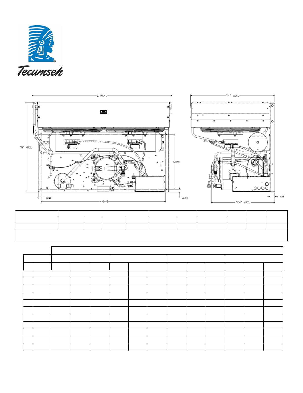
Dimensions, inches
Line Connection*
Pumpdown
Air
Oil Ch
Gr. Wt.
L W H
CH
Suction
Liquid
90 °F 90%
SCFM
Oz.
Lbs.
VSC9534ZNAXM
44.9
28.6
26.9
20.2
7/8” S
1/2” S
41 lbs.
4200
53
235
* F = Flare, S = Solder, RF or RS = Rotolock with Flare or Solder Connections, C = Compression Fitting
Factory charge: 20 PSIG Nitrogen – MUST BE EVACUATED
°F
PSIG
BTUH
Watts
Cond T
BTUH
Watts
Cond T
BTUH
Watts
Cond T
BTUH
Watts
Cond T
-10
23.2
19100
3790
91
17900
4280
101
16300
4720
110
14400
5130
120
-5
27.5
21000
3840
92
19600
4340
102
17900
4790
111
15800
5220
121
0
32.1
23500
3910
93
21900
4410
103
20000
4880
113
17700
5320
122
5
37.0
26600
4000
94
24700
4510
104
22500
4980
114
20100
5440
124
10
42.4
30100
4100
96
28000
4610
105
25500
5090
115
22900
5560
125
15
48.2
34000
4210
97
31500
4730
107
28800
5210
116
25900
5680
126
20
54.5
38200
4330
99
35300
4850
108
32200
5330
118
29100
5810
127
25
61.2
42500
4460
100
39300
4970
110
35900
5450
119
32300
5930
129
30
68.4
47000
4590
102
43400
5090
111
39500
5570
121
35700
6050
130
51500
4720
104
47400
5210
113
43200
5680
122
38900
6160
131
40
84.4
55900
4840
106
51400
5320
115
46700
5790
124
42000
6260
133
Tecumseh Compressor Company
Indoor Condensing Unit
Model: VSC9534ZNAXM BoM: 2A4097-1 R-404A 4 1/2 HP AIRCOOLED
December 1, 2014
Revision: REL
Model
Ambient Temperatures
Evaporator T, 80°F 90°F 100°F 110°F
35 76.1
60 Hz Performance
Return gas temp 40°F below 20°F evaporator, and 65°F above 20° evap, 5°F sub cooling
Page 2
Unit Model
VSC9534ZNAXM
High Pressure Switch
84095-2
Unit Bill of Material
2A4097-1
Low Pressure Control
84026-2
Check Valve
N/A
Refrigeration Range
-10° F to +45° F
Discharge Valve
31527-2
Design Pressure Low
181
Liquid Valve
56596
Design Pressure High
450
Suction Valve
31529-1
Nominal Volts-Hz-Ph
208-230/60/1
Voltage Range
197 - 254
Receiver Tank
51083
Min. Circuit Ampacity
34.2
Accumulator
TK00046000
Max. Fuse Size (amps)
50
Liquid Filter
N/A
Sight Glass
N/A
Compressor Model
VSC9530ZNA
Suction Filter
N/A
Comp. Bill of Material
VS224ET-104-J7
Compressor RLA/LRA
24.4/150
Unit Drawing
DGU1950-17
Overload
Internal
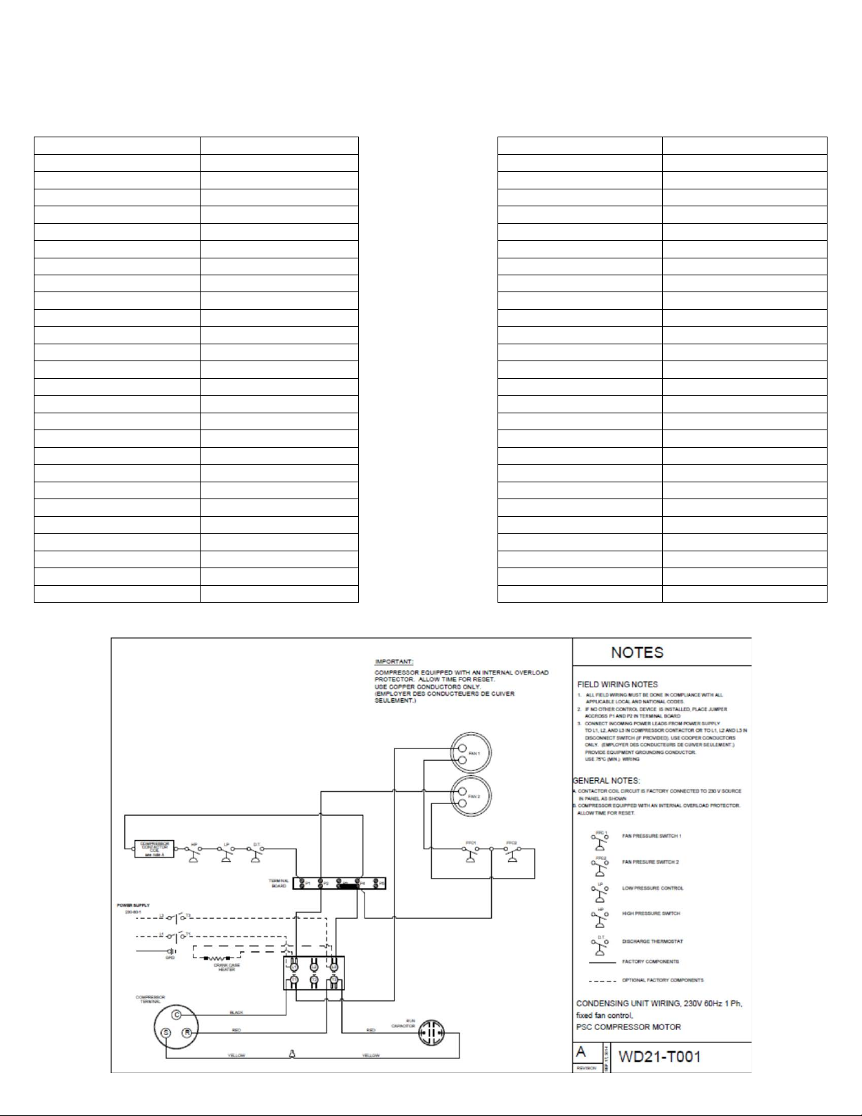
Wiring Diagram
WD21-T001
Relay
N/A
Run Capacitor
85PR370F29
Replacement Kit: Relay
N/A
Start Capacitor
N/A Replacement Kit: O/L
N/A
Contactor
91012H
Replacement Kit: St. Cap
N/A
Fan Motor
810S186B40 (2)
Fan Motor RLA
1.90
Fan Blade
51528-3 (2)
Fan Shroud
70611-1
Fan Guard
70832 (2)
Condenser
50785-4
Specifications/ Parts:
December 1, 2014
Revision: REL
Electrical Diagram
 Loading...