

Page 1

TECUMSEH
VLV
ENGINES
Not For Resale
www.SmallEngineDiscount.com
T E C H N I C I A N ' S H A N D B O O K
This manual covers VLV40 - 675.
Other illustrated Tecumseh 2-Cycle Engine, 4-Cycle Engine
and Transmission manuals; booklets; and wall charts are
available through Tecumseh.
For complete listing write or call
(VECTOR)
4-CYCLE
Page 2

TABLE OF CONTENTS
Not For Resale
www.SmallEngineDiscount.com
Chapter 1 General Information .............................................................................. 1
Engine Identification ........................................................................................... 1
Engine Breakdown .............................................................................................. 2
Parts List ............................................................................................................. 3
Engine Care ........................................................................................................ 4
Fuel, Oils, Storage .............................................................................................. 4
Tune-Up Procedure ............................................................................................ 5
4-Cycle Engine Theory ....................................................................................... 6
Chapter 2
Air Cleaners ..................................................................................................... 7-8
Carburetion ......................................................................................................... 9
Identification ........................................................................................................ 9
Parts Breakdown................................................................................................. 9
Float Bowl Service ............................................................................................ 10
Float Bowl Reassembly .................................................................................... 11
Float Bowl Drain........................................................................................... 10-11
Rebuilding the carburetor body ......................................................................... 11
Welch Plug Removal ........................................................................................ 11
Cleaning Welch Plug and Installation ............................................................... 11
Throttle Shaft & Shutter .................................................................................... 12
Primer Bulb ....................................................................................................... 12
Chapter 3
Governors and Linkage ............................................................................... 13-14
Chapter 4
Starters ............................................................................................................. 15
Rewind Starter ............................................................................................. 15-16
12 Volts Starters .......................................................................................... 17-18
Chapter 5
Flywheels and Servicing ................................................................................... 19
Removal and Assembly ............................................................................... 19-20
Brake System Operation ................................................................................... 20
Wiring ................................................................................................................ 21
Battery .............................................................................................................. 21
Replace Brake Pad ........................................................................................... 21
Brake Mechanism Installation ........................................................................... 22
Control Switch & Replacement ......................................................................... 22
Chapter 6
Alternator .......................................................................................................... 23
Troubleshooting Electric Start Engines ............................................................. 23
Chapter 7
Ignition System ................................................................................................. 24
Ignition System Operation ................................................................................. 24
Spark Plug Service ........................................................................................... 23
Timing Adjustment ............................................................................................ 24
Page 3

Chapter 8
Not For Resale
www.SmallEngineDiscount.com
Piston, Rings and Connecting Rod ................................................................... 25
Piston ................................................................................................................ 25
Rings ................................................................................................................. 25
Chapter 9
Cylinder and Cylinder Head Service ................................................................. 26
Reboring ........................................................................................................... 26
Cylinder Head ................................................................................................... 26
Chapter 10
Crankshaft, Camshaft and Lubrication.............................................................. 27
Crankshaft Timing Mark .................................................................................... 27
Camshaft Timing Mark ...................................................................................... 27
Compression Release....................................................................................... 27
Lubrication System Operation........................................................................... 28
Crankcase Breather Operation .................................................................... 28-29
Chapter 11
Valves, Lifters, Springs and Seats .................................................................... 30
Valve Removal .................................................................................................. 30
Valve Seats ....................................................................................................... 30
Valve Service .................................................................................................... 30
Valve Installation ............................................................................................... 31
Lifters ................................................................................................................ 31
Oversize Guides ............................................................................................... 31
Chapter 12
Removing the Mounting Flange ........................................................................ 32
Oil Seal Service ................................................................................................ 32
Mounting Flange Installation ............................................................................. 32
Chapter 13
Troubleshooting ........................................................................................... 33-39
Chapter 14
Engine Specifications ....................................................................................... 40
Torque Specifications ....................................................................................... 41
Chapter 15
Training Aids and Tools .................................................................................... 42
Chapter 16
Sears Craftsman Cross Reference ................................................................... 45
Tecumseh Products Company
C 1996
Page 4
Chapter 1
Not For Resale
www.SmallEngineDiscount.com
GENERAL INFORMATION
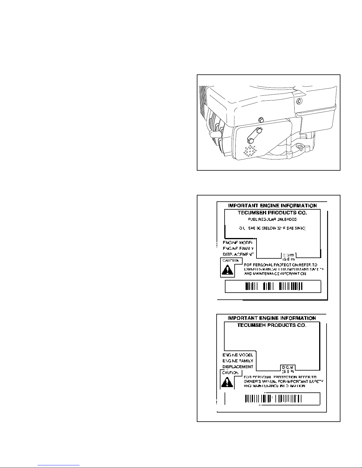
ENGINE IDENTIFICATION
Tecumseh engine model, specification and serial
numbers are stamped or decaled on the blower housing.
The decal also contains any emission compliance
information.
The letters which precede the model numbers indicate
the basic type of engine:
VLV - Vector Lightweight Vertical
The numbers which follow engine type letters indicate
the basic engine horsepower:
40 - 4.0 Horsepower
50 - 5.0 Horsepower
Following the engine size numbers are the engine
specifications numbers.
The specification number is used when identifying
engine parts example 502012A.
The serial number is the production date code.
7040 - serial number (example)
7 - Year in decade of manufacture (1997)
40 - The last 3 digits of date code represent the
calendar (the 40th day of 1997)
D - represents the shift and line on which the
engine was built at the factory.
VLV60-502012A
VLV60-502012A (D)
6215C
Emissionized engines that meet the California Air
Resource Board (C.A.R.B.) or the Environmental
Protection Agency (E.P.A.) standards will include
additional required engine information on the engine
decal.
NOTE: To maintain best possible emission
performance, use only Genuine Tecumseh Parts.
SHORT BLOCKS. New short blocks are identified by a
tag marked SBH (Short Block Horizontal) or SBV (Short
Block Vertical). These tags are used to properly identify
the correct parts if service is required. They are attached
to either the sump bolts or valve box cover.
THIS ENGINE MEETS 1995-1998
CALIF. EMISSION REGULATIONS FOR
ULGE ENGINES AS APPLICABLE
FUEL: REGULAR UNLEADED OIL: USE SAE 30
VLV60-502012A (D)
RTP358UIG2RA
207cc
6215C
1
Page 5
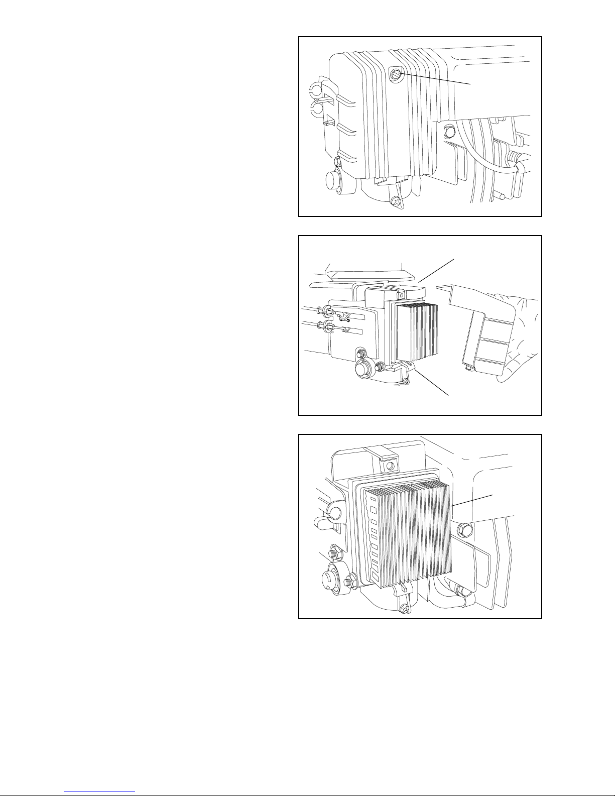
NOTE: On newer VLV models the breather
Not For Resale
www.SmallEngineDiscount.com
tube will be a straight hose.
OPTIONAL
PRE-FILTER
MODEL and SERIAL
NUMBERS HERE
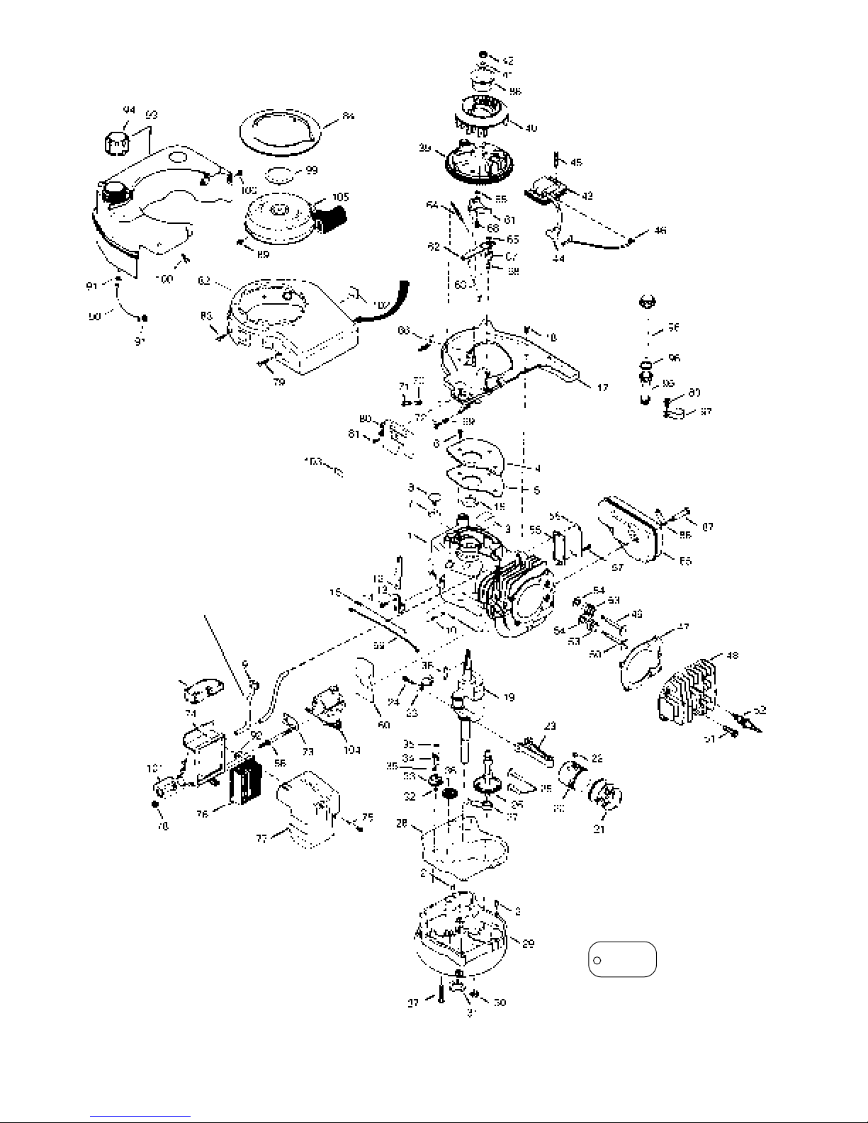
PARTS IDENTIFICATION
This is a parts breakdown of a typical VLV engine. Use this parts
breakdown to identify parts. When ordering parts always refer to the
engine model and specification number stamped on the engine blower
housing.
Carburetor and starter breakdowns are found in the chapters referring
to their repair.
2
SBV-XXX
SER-XXX
NOTE: If the short block has been
replaced, an identification tag for service
parts is located on the valve box cover.
Page 6

Ref.
Not For Resale
www.SmallEngineDiscount.com
No. Part Name
1 Cylinder Assy.
2 Pin, Dowel
3 Element, Breather
4 Cover, Breather
5 Gasket, Breather cover
6 Screw, Thread forming, 10-24 x 1/2
7 Body, Breather valve
8 Valve, Breather check
9 Breather, Tube
10 Washer, Flat
11 Rod, Governor
12 Lever, Governor
13 Clamp, Governor lever
14 Screw, 8-32 x 5/16
15 Spring, Governor extension
16 Seal, Oil
17 Baffle, Blower housing (Incl. No. 195)
18 Screw, 1/4-20 x 5/8
19 Crankshaft Assy.
20 Piston & Pin Assy.
21 Ring Set, Piston
22 Ring, Piston pin retaining
23 Rod Assy., Connecting
24 Bolt, Connecting rod
25 Lifter, Valve
26 Camshaft Assy.
27 Pump Assy., Oil
28 Gasket, Mounting flange
29 Flange, Mounting
30 Plug, Oil drain
31 Seal, Oil
32 Washer, Flat
33 Gear Assy., Governor
34 Spool, Governor
35 Ring, Retaining
36 Gear, Idler
37 Screw, 1/4-20 x 1-9/16
38 Key, Flywheel
39 Flywheel
40 Fan, Flywheel
41 Washer, Belleville
42 Nut, Flywheel
43 Solid State Assy.
44 Cover, Spark plug
45 Screw, 10-24 x 1
46 Wire Assy., Ground
47 Gasket, Cylinder head
48 Head, Cylinder
49 Valve, Exhaust
50 Valve, Intake
51 Screw, 5/16-18 x 1-1/2
52 Spark Plug (Champion RJ-19LM or equivalent)
53 Spring, Valve
Ref.
No. Part Name
54 Cap, Valve spring
55 Gasket, Valve cover
56 Cover, Valve spring box
57 Screw, 10-24 x 1/2
58 Stud, Carburetor mounting
59 Link, Governor
60 Spacer, Carburetor mounting gasket
61 Lever Assy., Brake
62 Lever, Brake control
63 Link, Brake control lever
64 Spring, Brake
65 Ring, Retaining
66 Terminal
67 Spring, Brake control lever
68 Bushing, Brake control leer & brake lever
69 Spring, Compression
70 Spring, Compression
71 Screw, 5-40 x 7/16
72 Screw, 6-32 x 21/32
73 Gasket, Carburetor to air cleaner
74 Body, Air cleaner (Incl. Nos. 239, 299 & 350)
75 Screw, 10-32 x 2-3/32
76 Filter, Air cleaner (Paper)
77 Cover, Air cleaner
78 Nut, Lock, 1/4-20
79 Screw, 1/4-20 x 11/16
80 Plate, Control Assy., cover
81 Screw, 8-32 x 1/2
82 Housing, Blower
83 Screw, 1/4-20 x 1/2
84 Ring, Starter
85 Muffler
86 Plate, Muffler locking
87 Screw, 5/16-18 x 2-11/32
88 Cup, Starter
89 Screw, 8-32 x 21/64
90 Line, Fuel
91 Clamp, Fuel line
92 Clip, "U" Type Nut, 10-32
93 Tank Assy., Fuel
94 Cap, Fuel
95 Tube, Oil fill
96 "O" Ring
97 Clip, Fill tube
98 Dipstick, Oil
99 Plug, Starter
100 Screw, 10-32 x 35/64
101 Primer
102 Decal, Instruction
103 Decal, Primer
104 Carburetor
105 Starter, Rewind
3
Page 7

ENGINE CARE
Not For Resale
www.SmallEngineDiscount.com
FUELS. Tecumseh Products Company strongly
recommends the use of fresh, clean, UNLEADED
regular gasoline in all Tecumseh engines. Unleaded
gasoline burns cleaner, extends engine life and
promotes good starting by reducing the build-up of
combustion chamber deposits. Gasoline, gasohol
containing no more than 10% ethanol, 15% M.T.B.E. or
ETBE, leaded fuel can be used if regular unleaded is
not available.
STORAGE
NEVER STORE ENGINE WITH FUEL IN TANK
INDOORS OR IN ENCLOSED, POORLY
VENTILATED ENCLOSURES, WHERE FUEL
FUMES MAY REACH AN OPEN FLAME, SPARK
OR PILOT LIGHT AS ON A FURNACE, WATER
HEATER, CLOTHES DRYER OR OTHER GAS
APPLIANCE.
If engine is to be unused for 30 days or more, prepare
as follows:
Never use gasoline containing METHANOL, gasohol
containing more than 10% ethanol, gasoline additives,
or white gas because engine/fuel system damage could
result. If engine is to be unused for 30 days or more see
“STORAGE” instructions.
ENGINE OIL:
USE A CLEAN, HIGH QUALITY DETERGENT OIL. Be
sure original container is marked: A.P.I. service “SF” or
“SG”.
DO NOT USE SAE 10W40 OIL.
FOR SUMMER (ABOVE 32oF) USE SAE 30 OIL.
Using multigrade oil may increase oil consumption.
FOR WINTER (BELOW 32oF) USE SAE 5W30 OIL.
(SAE 10W is an acceptable substitute.)
(BELOW 0oF ONLY): SAE 0W30 is an acceptable
substitute.
OIL CHANGE INTERVALS. Change oil after first two
(2) hours of operation and every 25 hours thereafter, or
more often if operated under dusty or dirty conditions.
OIL CHECK. Check oil every 5 hours or each time the
equipment is used. Position equipment so the engine is
level when checking the oil.
DRAIN INTO APPROVED CONTAINER
OUTDOORS, AWAY FROM OPEN FLAME.
1. DRAIN FUEL SYSTEM:
Remove all gasoline from carburetor and fuel tank
to prevent gum deposits from forming on these parts
and causing possible malfunction of engine.
NOTE: VLV engines are equipped with a bowl drain
screw. See Chapter 2 for removal procedure.
A. Run engine until fuel tank is empty and engine
stops due to lack of fuel.
B. Disconnect fuel line at carburetor or fuel tank.
Be very careful not to damage fuel line, fittings
or fuel tank.
Drain any remaining fuel from system. Properly
reconnect the fuel line.
NOTE: If gasohol has been used, complete
preceding instructions “A” and “B” and then put
a small amount of unleaded (or leaded regular)
gasoline into fuel tank and repeat preceding
instructions “A” and “B”.
NOTE: Fuel stabilizer (such as STA-BIL) is an
acceptable alternative in minimizing the
formation of fuel gum deposits during storage.
Add stabilizer to gasoline in fuel tank or storage
container. Always follow mix ratio found on
stabilizer container. Run engine at least 10
minutes after adding stabilizer to allow it to reach
carburetor.
2. If oil has not been changed recently, this may be a
3. Remove spark plug and put 1/2 oz. (15 ml) of clean
4. Clean engine by removing any clippings, dirt, or
4
good time to do it. See “CHANGE OIL” instructions
in “MAINTENANCE” section of the Owner’s Manual.
engine oil into spark plug hole. Crank engine over,
slowly, several times.
AVOID SPRAY FROM SPARK PLUG HOLE
WHEN CRANKING ENGINE OVER SLOWLY.
Reinstall spark plug.
chaff from exterior of engine.
Page 8

TUNE-UP PROCEDURE
Not For Resale
www.SmallEngineDiscount.com
CAUTION: Remove spark plug wire before
doing any service work on engine.
1. Service or replace air cleaner as necessary. (See
Chapter 2 Air Cleaners)
2. Inspect level and condition of oil, change or add oil
as required.
3. Remove blower housing, clean all dirt, grass or
debris from intake screen, head and cylinder cooling
fins and carburetor governor levers and linkage.
4. Make sure fuel tank, fuel filters and fuel lines are
clean. Replace any worn or damaged governor
springs or linkage. Make proper governor
adjustments where required. (See Chapter 3)
NOTE: If the engine is equipped with a Tecumseh
fuel tank, an integral filter is molded inside.
STANDARD
PLUG
9. Run engine and allow it to warm up for 5 minutes.
After the engine is warm, set the engine governed
RPM to specifications. This information is located
only on Micro Fiche Card 30 or the Plus One and
Parts Smart computer look-up systems.
5. Replace the spark plug with the proper spark plug.
Consult the parts breakdown for the spark plug to
be used in the engine being serviced. The spark
plug air gap is .030'’. Install spark plug in engine
and tighten to 15 foot pounds torque. If a torque
wrench isn’t available, screw spark plug in as far as
possible, by hand, and use a spark plug wrench to
turn spark plug 1/8 to 1/4 turn further when reusing
spark plug, or 1/2 turn further if using a new spark
plug.
6. Make sure all ignition wires are free of abrasions,
breaks and are properly routed so they will not rub
on flywheel.
7. Properly reinstall the blower housing, gas tank, and
fuel lines, then properly check for spark as stated in
the ignition section of this manual.
8. Make sure all cables are adjusted for proper
operation.
5
Page 9
4-CYCLE ENGINE THEORY
Not For Resale
www.SmallEngineDiscount.com
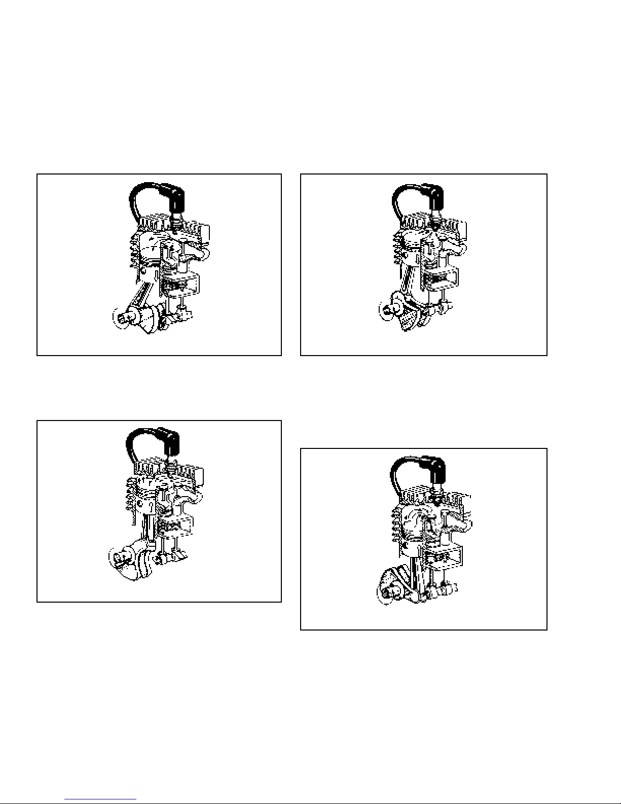
Tecumseh four-cycle engines require four strokes or
cycles to complete one power cycle.
1. INTAKE. Intake valve is open, exhaust valve is closed.
Piston is traveling downward creating a suction action,
drawing the fuel-air mixture from the carburetor into the
cylinder area above the piston.
1. INTAKE
2. COMPRESSION. As the piston reaches Bottom Dead
Center, the INTAKE valve closes. The piston then rises,
compressing the fuel and air mixture trapped in the
combustion chamber, because both valves are closed.
3. POWER. Both valves remain closed. As the piston
reaches the Before Top Dead Center (BTDC) ignition
point, the spark plug fires, igniting the fuel-air mixture.
In the time it takes to ignite all the available fuel, the
piston has moved to TDC (Top Dead Center), ready to
take the full combustive force of the fuel for maximum
power and piston downward travel. The expanding
gases force the piston down.
3. POWER
4. EXHAUST. Exhaust valve opens. As the piston starts
to the top of the cylinder, the exhaust gases are forced
out.
After the piston reaches Top Dead Center (TDC), the
four cycle process will begin again as the piston moves
downward and the intake valve opens.
2. COMPRESSION
NOTE: Some emission compliance engines may use a
RCR (Ramp Compression Relief) system. This system
opens the intake valve during the compression stroke
allowing a small amount of the intake charge back down
the intake pipe. This eliminates unburned fuel going out
the exhaust during normal compression relief cycle
typically used on the exhaust valve.
6
4. EXHAUST
Page 10
Chapter 2
Not For Resale
www.SmallEngineDiscount.com
AIR CLEANERS
CAUTION: Before removing air cleaner, make sure ALL
excess dirt is removed from around it.
NOTE: If the engine is equipped with an optional poly
pre-filter always remove it first, to prevent dirt falling into
the filter body.
Air cleaners must be serviced frequently, to prevent dust
and dirt from entering the engine. Dust mixed with the
engine oil forms an extremely abrasive compound which
quickly wears out an engine.
A clogged air cleaner will affect engine performance.
Replacing a restricted (clogged) air filter should restore
engine performance.
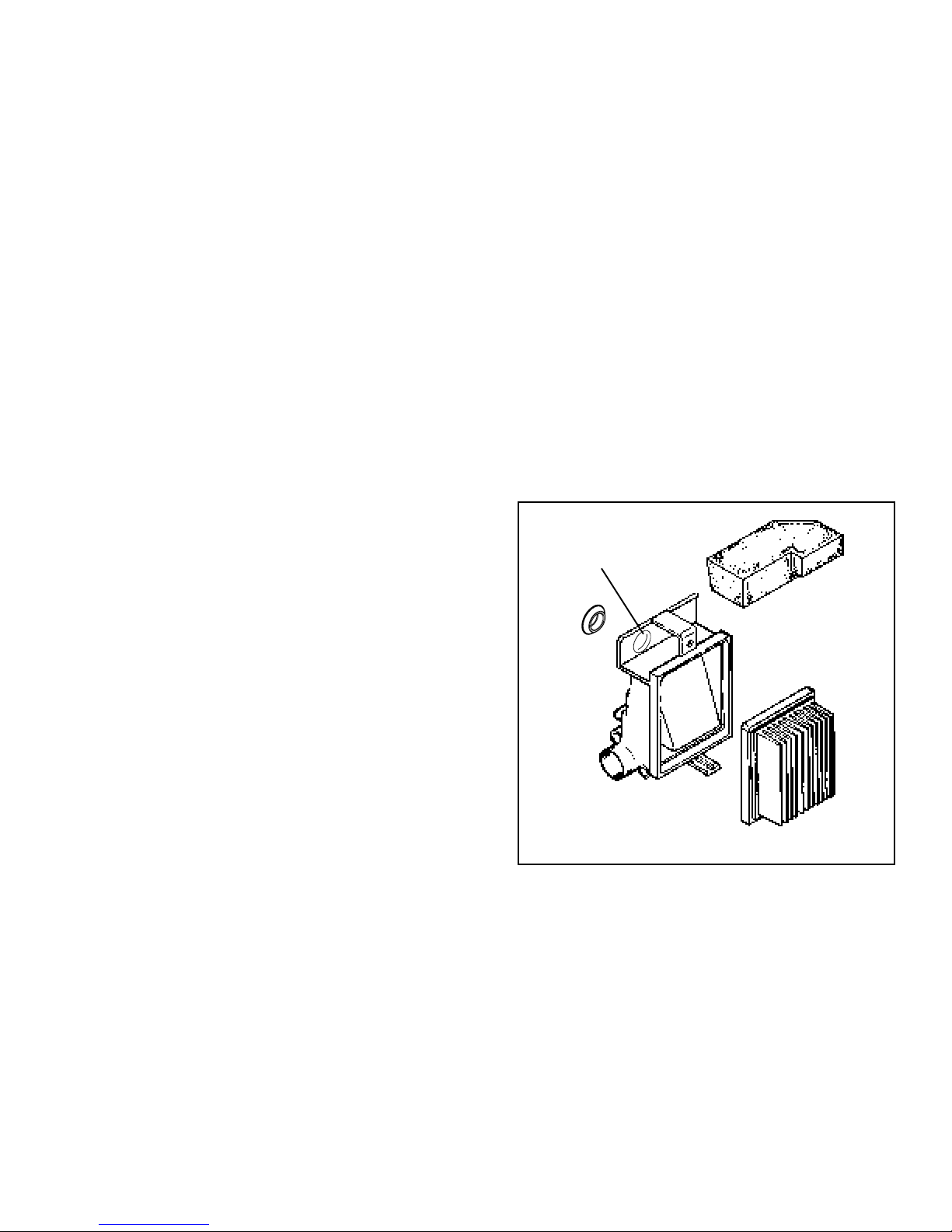
AIR CLEANER SERVICE. The engine utilizes a treated
paper element with a foam rubber-like sealing edge.
The seal must fit properly to prevent dirt ingestion.
Replace air filter once a year or more often in extremely
dusty or dirty conditions.
DO NOT ATTEMPT TO CLEAN OR OIL THE PAPER
FILTER.
Be sure to clean base and cover thoroughly before
installing new paper filter.
POLYURETHANE-TYPE PRE-FILTERS. These
serviceable air filters utilize a polyurethane element
which will clog up with use. The element should be
cleaned and serviced in the following manner.
Wash element in a detergent and water solution and
squeeze (don’t twist) until all dirt is removed. Rinse
thoroughly.
Wrap in a clean cloth and squeeze (don’t twist) until
completely dry.
Re-oil element by applying a generous quantity of oil to
all sides. Squeeze vigorously to distribute oil and to
remove excess oil.
Clean air cleaner housing and cover. Dry thoroughly.
Reinstall pre-cleaner in air filter body.
SOME VECTORS ARE
EQUIPPED WITH BOLT
ACCESS HOLE & A PLUG.
REPLACE IF REMOVED.
POLY
PRE-FILTER
NEVER RUN THE ENGINE WITHOUT THE
COMPLETE AIR CLEANER INSTALLED ON THE
ENGINE.
NOTE: Serious damage to the engine may result
from using any other but the specified part number
filter. Use factory recommended parts only.
Some models use a dual stage air cleaner. This air
cleaner uses a polyurethane-type foam pre-filter along
with the paper element.
PLUG
BODY
PAPER
FILTER
7
Page 11
TO SERVICE AIR CLEANER
Not For Resale
www.SmallEngineDiscount.com
1. Loosen cover screw (A).
A
2. Swing cover down and remove from hinge (B).
3. Pull foam pre-filter out of air cleaner body (if
equipped with pre-filter).
4. Pull air filter out of air cleaner body.
5. Clean air cleaner cover and body.
6. Install a new paper filter (part no. 36046) (C).
7. Clean and install pre-filter (if so equipped).
8. Reinstall cover to air cleaner body.
Be sure hinge is assembled properly.
9. Swing cover up and tighten cover screw. (Do not
over tighten).
PRE-FILTER
B
C
8
Page 12
CARBURETION
Not For Resale
www.SmallEngineDiscount.com
Proper Carburetion Function is dependent on clean fresh
fuel and a well maintained air cleaner system. Most
causes of carburetion problems are directly related to
stale fuel and dirt ingestion. Inspection of the carburetor
for dirt wear and fuel deposits should always be done
before servicing the carburetor.
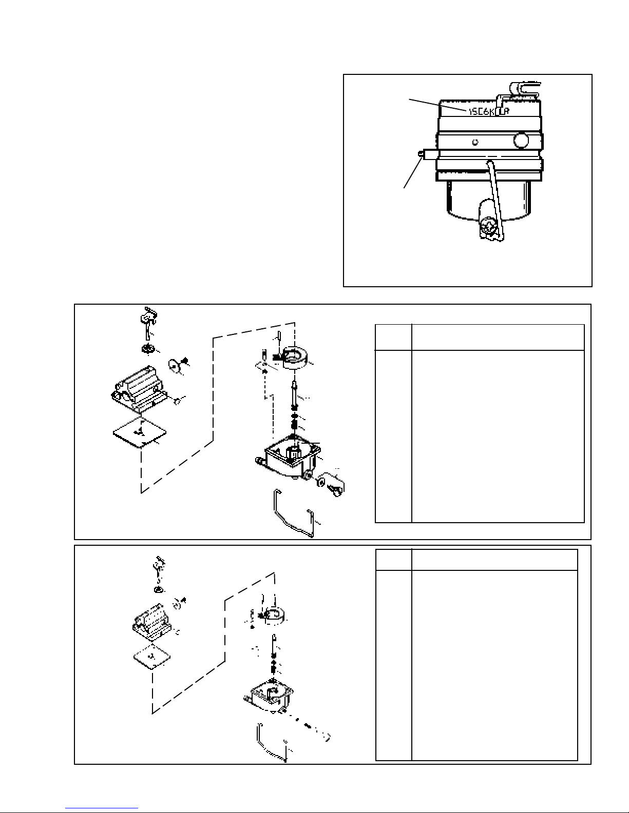
Carburetor Identification:
Tecumseh carburetors are identified by a manufacturing
number and date code stamped on the carburetor as
shown. When servicing carburetors, use the engine
model number or the manufacturing number on the
carburetor to find repair parts in the Master Parts Manual.
The engine has used both a split system and married
system carburetor. Below are the parts breakdowns for
the two carburetor's.
SPLIT
1
5
7
6
47
29
27
30
*
31
*
26
36
37
38
MANUFACTURING NUMBER
AND DATE CODE
TORX E-5
STUD
NOTE: LATER MODEL VECTOR CARBURETOR BODIES ARE
HELD ON WITH TORX E-5 STUDS. YOU WILL NEED THIS
SOCKET FOR REMOVAL. TECUMSEH PART NO. 670339.
Ref.
No. Part Name
1 Throttle Shaft & Lever Assy.
5 Dust Seal (Throttle)
6 Throttle Shutter
7 Throttle Shutter Screw
25 Float Bowl
25A Idle Restrictor
26 Float
27 Shaft, Float
29 Gasket, Float Bowl to Body
25A
25
32
39
30 Inlet Needle, Seat & Seat Retainer (Incl. 31)
*
31 Seat Retainer
*
32 Bowl Drain Assy.
36 Tube, Main Nozzle
37 O Ring, Main Nozzle Tube
38 Spring, Main Nozzle Tube
39 Float Bowl Retainer
47 Welch Plug, Idle Mixture Well
MARRIED
1
5
7
6
47
29
NOTE: The seat retainer may not be present on some engines. If you receive a retainer as a service part, install it.
*
27
36
37
38
26
25A
25
37A
39
40
30
*
31
*
38A
33
32
Ref.
No. Part Name
1 Throttle Shaft & Lever Assy.
5 Dust Seal
6 Throttle Shutter
7 Throttle Shutter Screw
25 Float Bowl
25A Idle Restrictor
26 Float
27 Float Shaft
29 Gasket, Float Bowl to Body
30 Inlet Needle, Seat & Seat Retainer (Incl. 31)
*
31 Seat Retainer
*
32 Bowl Drain Screw
33 Bowl Drain Washer
36 Tube, Main Nozzle
37 O Ring, Main Nozzle Tube
37A O Ring
38 Spring, Main Nozzle Tube
38A Spring
39 Float Bowl Retainer
40 Main Fuel Jet
47 Welch Plug, Idle Mixture Well
9
Page 13
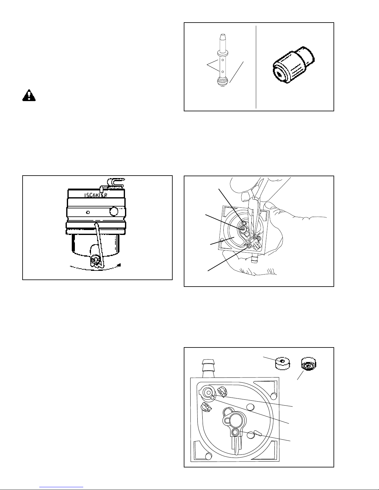
The carburetor is a float feed, nonadjustable type,
Not For Resale
www.SmallEngineDiscount.com
with a 1 piece extruded aluminum body. The float
bowl, float, nozzle, and venturi are nonmetallic,
minimizing the corrosion and varnishing problems.
Common service areas of the carburetor are contained
in the fuel bowl. These areas are the float, needle,
seat and main nozzle. All of these parts can be serviced
without removing the carburetor body from the engine.
DRAIN INTO APPROVED CONTAINER
OUTDOORS, AWAY FROM OPEN FLAME.
FLOAT BOWL SERVICE. Disconnect and plug the fuel
line. Remove the bowl drain screw. Remove the float
bowl by snapping the bale spring towards the throttle
end of the carburetor.
IF A SCREW DRIVER OR SIMILAR TOOL IS USED
TO AID IN THE BAIL REMOVAL, CARE MUST BE
TAKEN NOT TO PERMANENTLY BEND THE
RETAINER.
AIR
BLEED
HOLES
SPLIT SYSTEM MAIN JET
JET AND NOZZLE ASSY.
"O" RING
MARRIED SYSTEM MAIN JET
The float is held in the float bowl by the float pin which
is pressed into tabs on top of the float support towers.
NOTE: To prevent damage to the float bowl, pull straight
up with a needle nose pliers in the pocket closest to the
main fuel well. Carefully lift the float out of the float bowl
and inspect for damage or deposits. Clean the idle
passageway with compressed air, or with tag wire.
IDLE PASSAGE
After the bowl gasket is removed, the parts contained
in the bowl can be inspected and serviced. Pull out the
main nozzle and spring. Inspect the main nozzle for
deposits, be sure to check the cross holes on the body
of the nozzle and the main orifice in the bottom of the
nozzle. Use compressed air or monofilament fishing
line to remove any deposits in the main jet or cross holes.
Remove the drain screw to access the spring, jet and
"O" ring. The main jet should be inspected and cleaned
if deposits exist.
MAIN NOZZLE
FLOAT
HINGE PIN
NOTE: The inlet needle is attached to the float and
should also be inspected for damage or deposits.
The inlet seat can be removed with a small wire hook or
a #2 crochet hook. Inspect the float bowl and main
nozzle area for sediment and deposits. Use a carburetor
cleaner to loosen and remove deposits and sediment.
INLET NEEDLE
SEATS AT
THIS POINT
INSERT GROOVED
FACE FIRST
10
INLET SEAT
RETAINING CLIP
IDLE PASSAGE
Page 14
5/32" FLAT PUNCH
Not For Resale
www.SmallEngineDiscount.com
SEAT
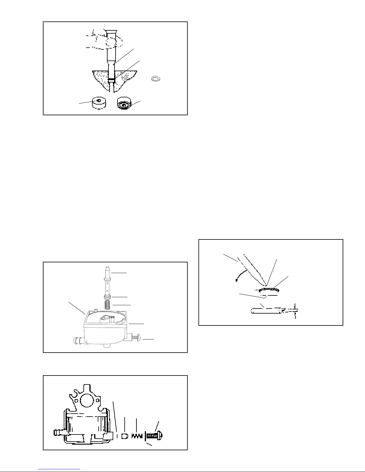
Place a new gasket on top of the float bowl with the
notch on the gasket aligned with the bump on the bowl
edge (the gasket will only fit onto the float bowl one
way.) Hold the float bowl to the carburetor body and
snap the retainer into position. Reinstall the bowl drain
screw, do not over tighten, reattach the fuel line.
PRESS IN UNTIL
SEAT RESTS ON
BODY SHOULDER
INLET NEEDLE
SEATS AT
THIS POINT
RETAINING CLIP
INSERT GROOVED
FACE FIRST
Install a new inlet seat into the float bowl. The grooved
side of the inlet seat goes into the float bowl first. Place
a drop of oil on the seat and press it in with a flat punch
until it seats. Do not scratch the inlet bore.
NOTE: Some models are equipped with a fuel inlet seat
retaining ring. If your replacement seat set comes with
a retaining clip install it on top of the seat.
Slide the inlet needle into the tabs on the float and put
the float pin into the hinge on the float. Carefully set the
float into position in the float bowl.
Be sure the needle drops into the fuel inlet. Snap the
float shaft into the tabs in the float bowl. It is not
necessary to adjust the float height even if the float has
been replaced.
Drop the main nozzle spring into the main nozzle well
in the float bowl. Put a small amount of oil on the main
nozzle “O” ring and push the nozzle into the main nozzle
well, “O” ring end first.
NOTE: Bowl service is all that is normally required for
routine carburetor maintenance.
Rebuilding the carburetor body:
Before disassembling the carburetor body, check the
throttle shaft and body for excessive wear. If there is
excessive wear to the throttle body, it should be
replaced.
To rebuild the carburetor body it is necessary to remove
the carburetor from the engine.
1. Remove the speed control plate.
2. Remove the air cleaner body from the carburetor.
3. Disconnect and plug the fuel line.
4. Remove the carburetor mounting studs.
5. Remove the governor link.
6. Drain the carburetor float bowl.
7. Disassemble the float bowl (see bowl service).
To properly clean the carburetor body, the welch plugs
should be removed to expose drilled passages. To
remove welch plug, sharpen a small chisel to a sharp
wedge point. Drive the chisel into the welch plug, push
down on chisel and pry plug out of position.
SMALL CHISEL
PIERCE PLUG WITH TIP
SPLIT SYSTEM
GASKET
ALIGNMENT
MARKER
MAIN NOZZLE
BLEED/JET
"O" RING IN GROOVE
SPRING
BOWL
DRAIN
In addition to this, the married system carburetor has
the "O" ring, main jet, and spring located behind the
drain system.
MARRIED SYSTEM
"O" RING
JET
SPRING
DRAIN SCREW
PRY OUT PLUG
DO NOT ALLOW
CHISEL POINT
TO STRIKE
CARBURETOR
BODY OR CHANNEL
REDUCER
SMALL CHISEL
WELCH PLUG TO
BE REMOVED
ABOUT 1/8" WIDE
After the welch plug is removed from the carburetor it
can be soaked in a commercial carburetor cleaner no
longer than 30 minutes. Be sure to follow the directions
on the container.
NOTE: Always pull the non metallic slip in venture out
before soaking in carburetor cleaner.
Reinstall the venture using the main nozzle to align it
correctly. The air bleed passages face the air filter.
After the carburetor has been soaked, all passages may
be probed with monofilament fishing line and
compressed air to open plugged or restricted passages.
GASKET
11
Page 15
Install a new welch plug over the idle fuel chamber with
Not For Resale
www.SmallEngineDiscount.com
the raised portion up. Use a punch equal to the size of
the plug, to flatten the plug. Do not dent or drive the
center of the plug below the top surface of the carburetor.
NOTE: To insure a good seal on this plug, we
recommend coating the seam with nail polish which is
gas resistant.
FLAT END PUNCH
Primer Bulb Service: To remove the primer bulb, grasp
the primer bulb with a needle nose pliers and roll the
pliers along the air cleaner body. After removing the
primer bulb, the retaining ring must be removed. Use a
screwdriver to carefully pry the retainer out of the air
cleaner body. Do not reuse old bulb or retainer.
NEW WELCH PLUG
SAME
DIAMETER OF PLUG
Install the throttle shaft and shutter (use a new shutter
screw and dust seal). The scribe mark on the shutter
must be in the 12 o’clock position.
NOTE: NEWER STYLE
CARBURETORS USE A
TORX T-10 SCREW
12 O'CLOCK POSITION
NOTE: THE BREATHER
SYSTEM HOSE MUST BE
RECONNECTED HERE.
NOTE: If the scribe mark is out of position the shutter
may stick.
To rebuild the Float Bowl, refer to the previous section
on float bowl service.
Install the carburetor to the engine using a new gasket.
The primer passage in the air cleaner body should be
cleaned before it is reinstalled over the carburetor.
After the primer bulb is removed, clean the primer
passages thoroughly.
Press the new bulb and retainer into position using a
deep reach socket as shown.
CAUTION: Wear safety glasses or goggles when
removing retainer.
Install air cleaner body over the carburetor using a new
gasket.
NOTE: The VLV models use a closed loop breather
system. The crankcase breather tube must be
reconnected to the air filter body
12
Page 16
Chapter 3
Not For Resale
www.SmallEngineDiscount.com
GOVERNORS AND LINKAGE
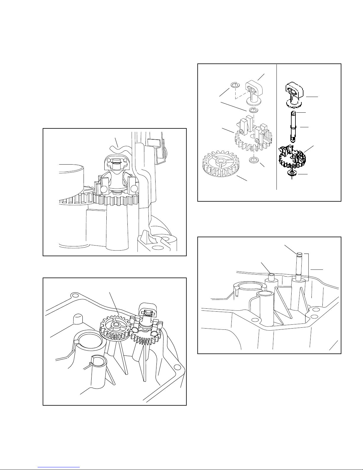
All Tecumseh 4-cycle engines of recent manufacture
are equipped with mechanical type governors. As the
speed of an engine increases, centrifugal force moves
the weights outward, lifting up the governor spool which
contacts the governor shaft; this in turn closes the
throttle. As engine speed decreases, the weights are
pulled inward by the spring which opens the throttle.
Thus, the engine speed controls the throttle opening
and maintains a certain governed speed.
CENTER FORCE GOVERNOR
SPOOL
RETAINING
RING
GEAR ASSY.
(GOV.)
WASHER
IDLER
GEAR
NOTE: Gear assembly must have .010 - .020 end play after shaft is
installed into flange.
VLV TYPE IITYPE I
SPOOL
UPSET
RETAINER
SHAFT
GEAR ASSY.
(GOV.)
WASHER
TYPE II governors do not use governor retainer clips.
The spool is retained by a raised upset on the shaft.
The governor shaft is pressed into the flange or cover
to a specific dimension as shown below.
The governor gear on this engine is driven by the
crankshaft through an idler gear as shown below.
IDLER GEAR
GOVERNOR SHAFT
IDLER SHAFT
PRESS
DEPTH
1.319
1.334
13
Page 17

Linkage Installation: The solid link is always connected
Not For Resale
www.SmallEngineDiscount.com
from the throttle lever on the carburetor to the lower
hole on the governor lever. The shorter bend has to be
toward the governor. The governor extension spring is
connected with the spring end hooked into the upper
hole of the governor lever and the extension end hooked
through the speed control lever. To remove the governor
spring, carefully twist the extension end
counterclockwise to unhook the extension spring at the
speed control lever. Do not bend or distort governor
extension spring.
TWIST COUNTERCLOCKWISE
TO DISCONNECT
GOVERNOR SPRING
Speed Controls: This engine has an adjustable speed
control. Never exceed the manufacture’s recommended
speeds.
HIGH SPEED ADJUSTMENT
COUNTERCLOCKWISE INCREASES SPEED
LOW SPEED ADJUSTMENT
COUNTERCLOCKWISE INCREASES SPEED
SHORT BEND
Õ
LONG BEND
Õ
Governor Adjustment. With engine stopped, loosen
the screw holding the governor clamp and lever. Turn
the clamp clockwise, then push governor lever
connected to the throttle to a full wide open throttle
position. Hold the lever and clamp in this position and
tighten the screw.
NOTE: Governor adjustment screw will be Torx head
(T-10) effective August 1, 1996 for E.C. Compliance.
14
Page 18

Chapter 4
Not For Resale
www.SmallEngineDiscount.com
STARTERS
REWIND STARTER
DISASSEMBLY PROCEDURE.
1. After removing the rewind assembly from the engine,
remove the starter handle by first pulling a length of
rope out using the handle, tie a temporary knot in
the exposed rope, then untie the knot in handle or
pry out the staple.
2. Untie the temporary knot and slowly allow the rope
to fully retract into the starter housing and the recoil
spring to fully unwind.
3. Place a 3/4'’ deep reach socket under the retainer
pawl. Set the rewind on a bench, supported on the
socket.
4. Using a 5/16'’ roll pin punch, drive out the center
pin.
5. All components that are in need of service should
be replaced.
THIS REWIND SPRING IS NOT IN A CANISTER.
Care must be used when handling the pulley because
the rewind spring and cover are held together by the
bosses in the pulley.
LEFT-HAND
KNOT
DOG SPRING
STARTER DOG
RETAINER PIN
REINSTALL RETAINER
PIN 1/8" FROM TOP
FRICTION WASHER
RETAINER COVER
SPRING
WASHER
ASSEMBLY PROCEDURE.
1. Reverse the above listed procedure keeping in mind
that the starter dogs with the dog springs must snap
back to the center of the pulley.
2. Always replace the center pin with a new pin upon
reassembly. Also place the two new plastic washers
between the center leg and retainer pawl. Discard
old plastic washer. The new plastic washers will be
provided along with the new center pin.
3. Check retainer pawl. If it is worn, bent or damaged
in any manner replace upon reassembly.
Install the new center pin in until it is within 1/8 of an
inch of the top of the starter.
CAUTION: Driving the center pin in too far will cause
the retainer pawl to bend and the starter dogs will not
engage the starter cup.
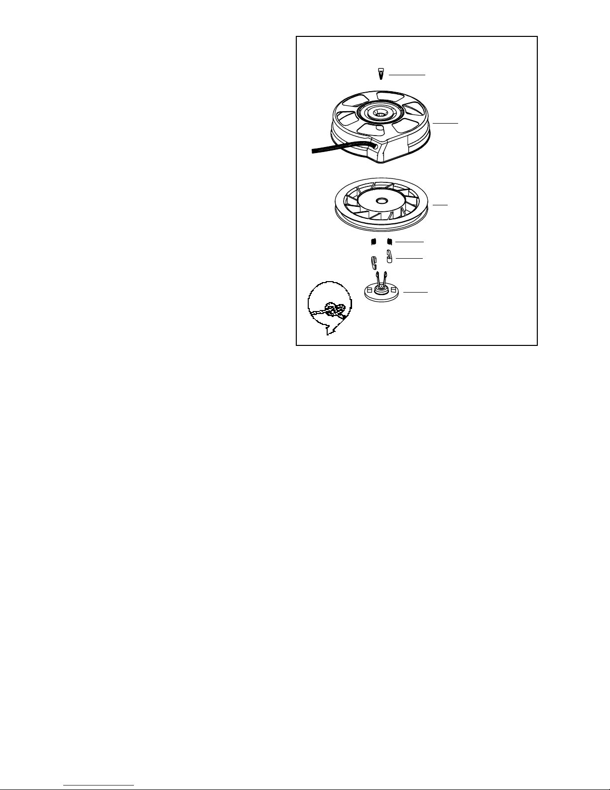
STYLIZED REWIND STARTER WITH
PLASTIC RETAINER
Disassembly Procedure
1. After removing the rewind assembly from the engine,
remove the starter handle by first pulling a length of
rope out using the handle, tie a temporary knot in
the exposed rope, then either untie the knot in handle
or pry out the staple.
NOTE: Always replace the decal or plug over the roll pin
or wedge to prevent moisture infiltration.
RETAINER WEDGE
STARTER
HOUSING
STARTER PULLEY
SPRING & COVER
DOG SPRING
STARTER DOG
DOG RETAINER
15
Page 19
2. Untie the temporary knot and slowly allow the rope
Not For Resale
www.SmallEngineDiscount.com
to fully retract into the starter housing and the recoil
spring to fully unwind.
3. Remove the decal from the center of the starter
housing.
RETAINER WEDGE
4. Use a small Phillips screwdriver or similar tool to pry
the retainer legs apart and lift out the retaining
wedge.
5. Pinch the legs of the retainer together and pull on
the head of the retainer to remove it from the housing.
6. Remove the pulley assembly from the recoil housing.
7. Repair or replace as necessary.
Assembly
1. If replacing the starter rope, see Step 8.
NOTE: EXTREME CAUTION AND APPROPRIATE
SAFETY EQUIPMENT MUST BE USED WHEN
WORKING WITH RECOIL SPRINGS.
2. Install a new recoil spring if necessary by pushing
the new spring out of the holder into the pulley cavity
while aligning the outside spring hook into the deep
notch in the pulley. Push the spring cover in until
seated.
3. Apply a small amount of lithium grease to the inner
bore of the center shaft.
LEFT-HAND
KNOT
STARTER
HOUSING
STARTER PULLEY
SPRING & COVER
DOG SPRING
STARTER DOG
DOG RETAINER
4. Replace or check that both starter dogs are in the
pulley pockets and that the dog springs are hooked
on the outer surface of the dog.
5. Pinch the two legs of the plastic retainer together
and start into the center shaft hole.
6. Rotate the retainer so the two tabs on the bottom of
the part fit between the dog and pulley hub (left side
of the dog). Push the retainer in until the leg prongs
pop out of the center shaft.
7. Turn the starter over and snap the locking tab
between the retainer legs, replace the top decal.
8. Carefully turn the pulley counterclockwise until it
stops. Then back the pulley up until the recoil
grommet hole and the pulley hole are aligned. Next
using a rope with a cauterized end, feed it into the
pulley hole. Tie a left handed knot and allow the rope
to be drawn into the recoil slowly.
16
Page 20

12 Volt Electric Starters
Not For Resale
www.SmallEngineDiscount.com
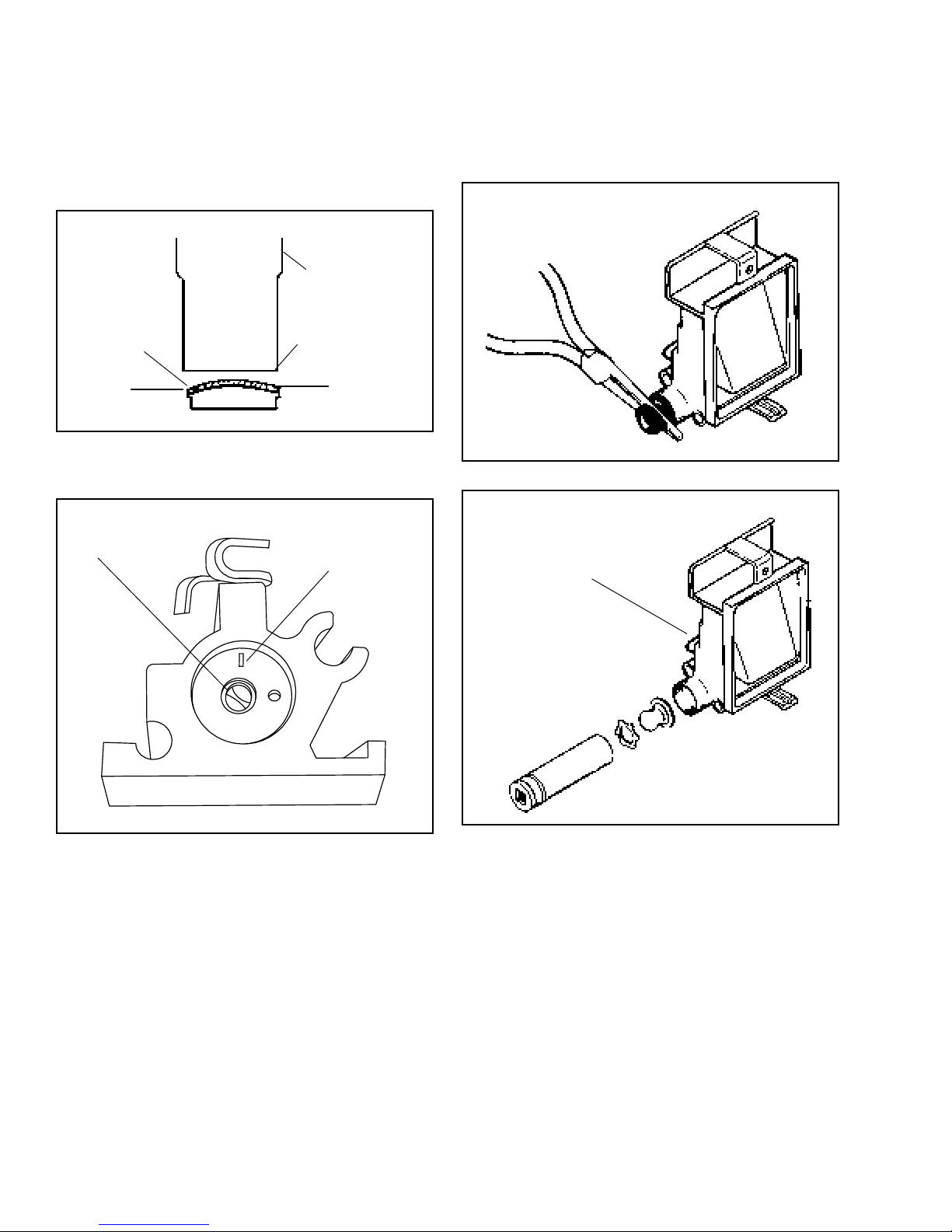
ELECTRIC STARTER REMOVAL. Remove face plate,
air cleaner assembly and gas tank. Compress plastic
grommet and pull it out of the blower housing. Slide the
wire through slot, being careful not to cut the wire
insulation. Remove blower housing, remove flywheel
(see flywheel section) and inspect ring gear for wear or
damage. Replace if necessary (see flywheel section).
Remove nuts on both sides of pinion. Drop starter out
of back plate and remove ground wire.
Remove, inspect and replace as necessary. Use
reverse procedure for assembly. (For ease of assembly
assemble armature into brush end frame first.) Place a
small amount of light grease such as lubriplate between
the drive nut (3) and helix on armature shaft. DO NOT
apply lubricant to pinion driver.
END CAP
AND BRUSH
(ASSEMBLY)
CHECK BRUSHES. Before removing armature, check
brushes for wear. Make sure brushes are not worn to
the point where brush wire bottoms out in the slot of
brush holder. Brush springs must have enough strength
to keep tension on the brushes and hold them against
the commutator. If brushes are in need of change,
replace the entire end cap assembly.
DRIVE ASSEMBLY SERVICE. Pinion gear parts should
be checked for damage or wear. If the gear does not
engage or slips, it should be washed in solvent (rubber
parts cleaned with soap and water) to remove dirt and
grease, and dried thoroughly. If damaged, replace parts.
PARTS LIST:
1. Retainer ring
2. Dust washer
3. Drive nut
4. Pinion driver
5. Gear
6. Anti-drift spring
7. Spring retainer (spring collapses into retainer)
8. Cup washer (cup washer cupped over retainer
spring)
9. Washer (metal)
10. Retainer ring
11. Thrust washer (metal)
12 Washer (plastic)
13. Lock nuts
14. Cap assembly drive end
15. Armature
16. Housing
17. End cap and brush card assembly
18. Bolts
ARMATURE CHECK. If commutator bars are glazed
or dirty, they can be turned down in a lathe. While
rotating, hold a strip of 00 sandpaper lightly on the
commutator, moving it back and forth. (Do not use
emery cloth.) Recut grooves between commutator bars
to depth equal to the width of the insulators.
Using a continuity tester to make certain no continuity
exists between the commutator (copper) and the iron of
the armature, rotate armature and check out all
commutator bars.
The armature can be thoroughly checked with a growler
if available.
17
Page 21
ELECTRIC STARTER ASSEMBLY
Not For Resale
www.SmallEngineDiscount.com
ATTACH THE GROUND WIRE prior to assembling the
electric starter to the baffle, attach the black ground wire
to the electric starter through bolt so the the wire extends
between the two adjacent end cap prongs (illustration).
Place the starter into the back plate with the ground
wire bolt away from carburetor (see picture). Note that
the throttle linkage is routed around starter while the
governor spring is routed through the end cap prongs
(illustration).
STARTER PRONGS
Tighten nuts on starter bolts (see specifications). Place
blower housing on engine and slide wires through slot
making sure not to cut insulation. Press grommet into
hole. Reassemble gas tank, air cleaner assembly and
face plate.
ATTACH GROUND
WIRE
BATTERY GROUND
LEAD ATTACHED TO
ELECTRIC STARTER
MOTOR STUD BEFORE
ELECTRIC STARTER
MOTOR IS ATTACHED
TO BLOWER HOUSING
BAFFLE
18
Page 22

Chapter 5
Not For Resale
www.SmallEngineDiscount.com
FLYWHEELS
This engine uses one of two types of flywheels. The
first type is a cast iron high inertia flywheel. This type of
flywheel will have a pressed on steel ring gear if the
engine is equipped with an electric starter. The steel
ring gear is nonserviceable. The second and most
popular style of flywheel is diecast aluminum. The
aluminum flywheel features a replaceable plastic fan
and a nonserviceable plastic ring gear when equipped
with an electric stater. Disconnect battery before
servicing.
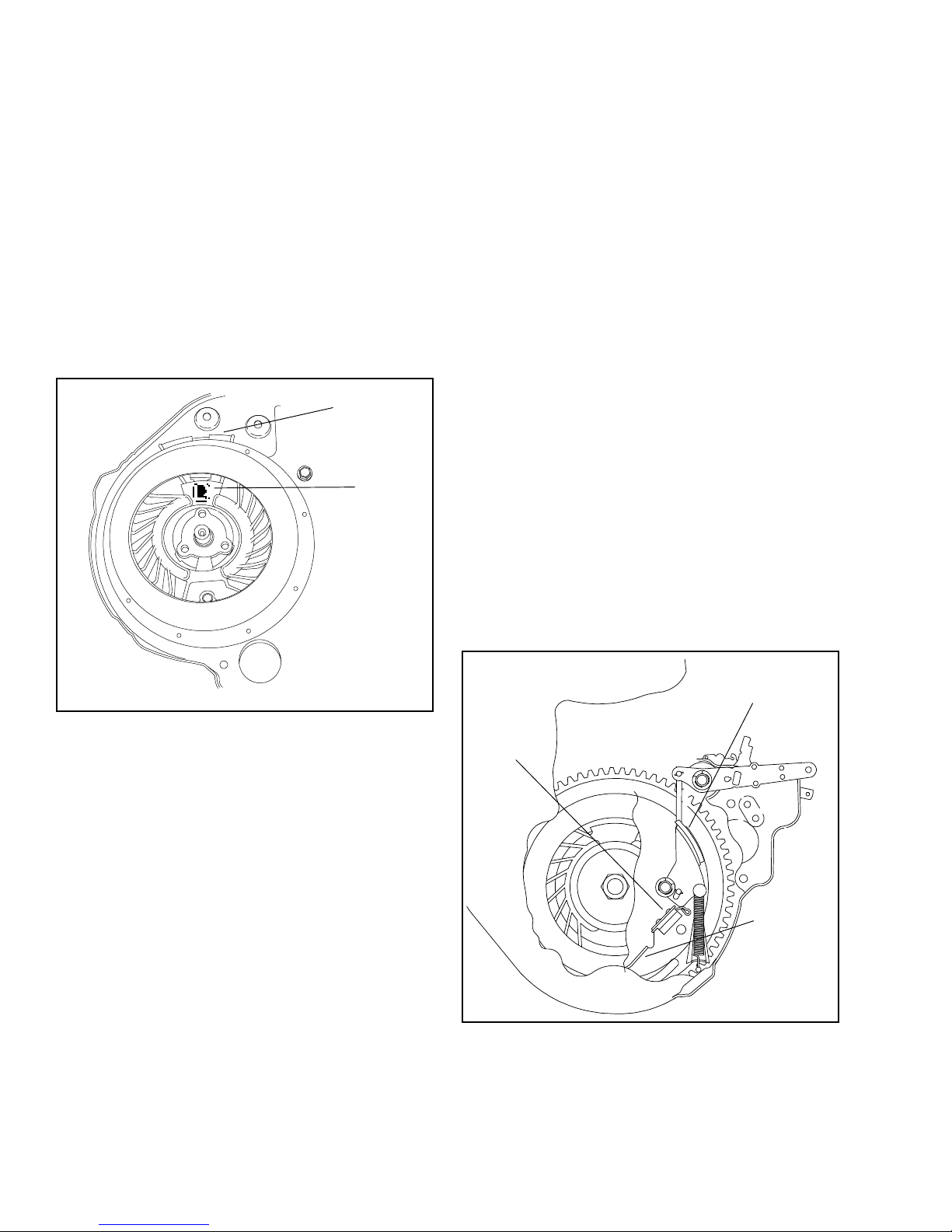
FLYWHEEL REMOVAL. Remove the ignition module.
Remove the brake pressure from the flywheel. The brake
can be locked in the disengaged position by placing a
pin into one of the aligned holes in the backing plate
lever assy.
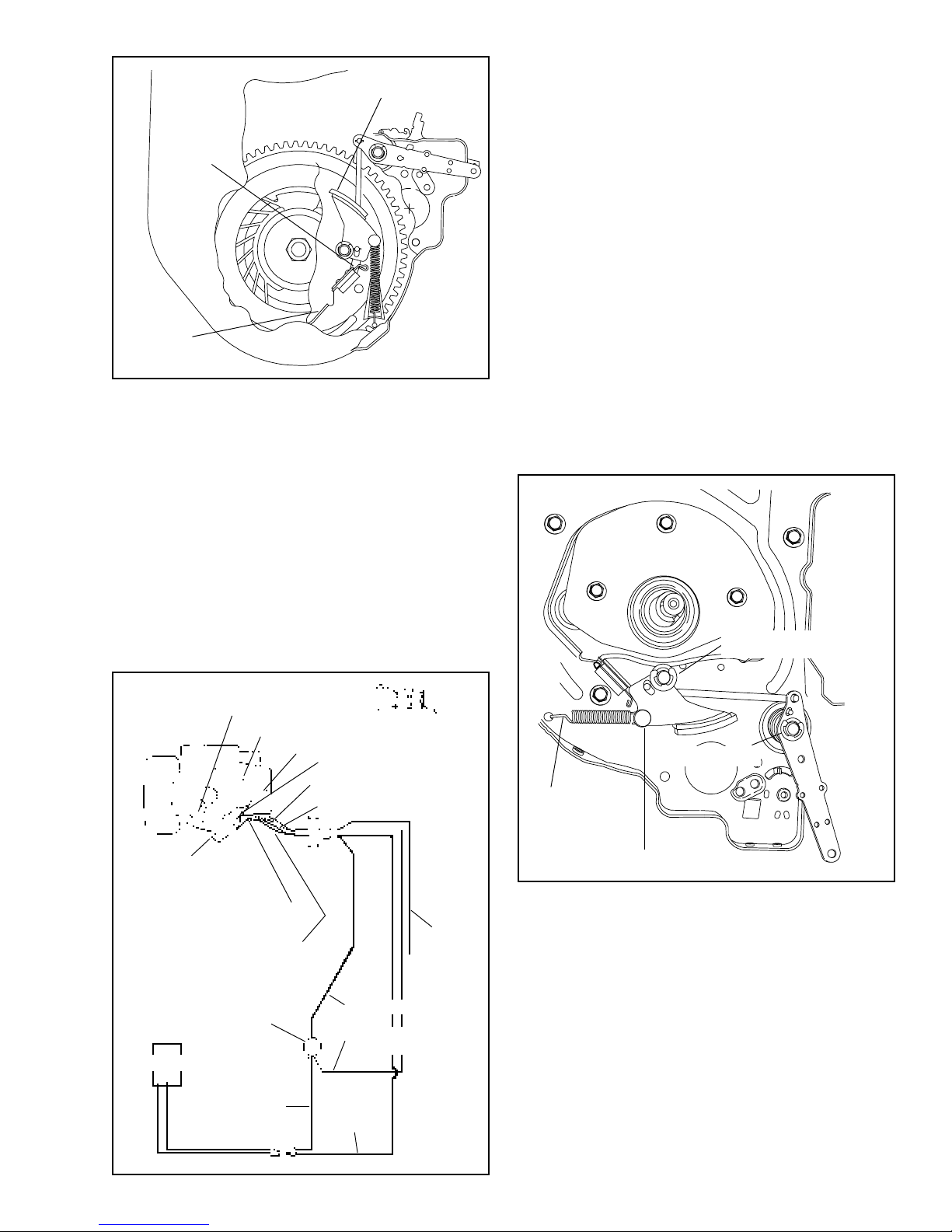
To remove the flywheel nut, use a flywheel strap wrench
(670305) to hold the flywheel, while turning the flywheel
nut counterclockwise.
On engines with cored holes (not tapped) use flywheel
puller Part No. 670306.
Screw the knock-off (no. 670169) tool down until it
touches the flywheel, then back off 1 turn. Using a large
screwdriver, pry upward under the flywheel (side
opposite the brake) and tap sharply and squarely on
the knock-off tool to break the flywheel loose. If
necessary rotate flywheel a half turn and repeat until it
loosens.
NOTE: Do not attempt to remove flywheel using a jaw
type puller on the outer diameter of the flywheel or
flywheel breakage will occur.
NOTE: Never use a pry bar with any type of curve on
the end. Breather cover damage can result.
DROP PIN THROUGH
TO DISENGAGE BRAKE
Lift the starter cup and fan off of the flywheel. (Aluminum
flywheel only)
Remove the flywheel using a flywheel puller or knockoff tool.
19
Page 23
FOR FLYWHEEL REASSEMBLY (INSTALLATION).
Not For Resale
www.SmallEngineDiscount.com
1. Inspect brake pad to be free of dirt, oil or grease. If
pad is contaminated, or less than .060'’ at the
narrowest point, replace. See flywheel brake section
for procedure.
2. Compress brake lever
3. Install flywheel key
4. Install flywheel
5. Install the fan onto the flywheel so the Tecumseh
logo on the fan is on the magnet side of the flywheel.
6. Place starter cup into position and torque flywheel
nut to specification. Use a strap wrench to hold the
flywheel.
MAGNET
LOGO
2. Use of a recoil starter (top or side mounted) with
the rope handle on the engine as opposed to within
24 inches of the operator position. This method is
acceptable if the mower deck passes the 360
degree foot probe test. A specified foot probe must
not contact the blade when applied completely
around the entire blade housing. This alternative
can be used with engine mounted brake systems
and typical bail controls. The blade stops within three
seconds after the operator lets go of the blade
control bail at the operator position and the engine
is stopped.
Tecumseh’s Flywheel Brake System provides consumer
safety by shutting down the engine and lawnmower
blade within seconds after the operator releases an
Engine/Blade control at the handle of the lawnmower.
The Brake Starter Mechanism may be used with either
of two options for starting:
1. Manual Rope Start
2. 12 Volt Starter System
Each system requires the operator to start unit behind
mower handle in operator zone area. The electric start
system also provides a charging system for battery
recharge when engine is running.
BRAKE SYSTEM
Tecumseh’s brake system provides a method of meeting
compliance standards which became law as of June
30, 1982. There are two additional methods used by
equipment manufacturers that also meet compliance
standards and they are as follows:
1. B.B.C. Blade Brake Clutch: This system is
designed to stop the blade from rotating, in
compliance with the 3 second stopping regulation,
after operator lets go of the safety bail. This system
allows the engine to continue running while stopping
the blade. B.B.C. systems are installed by various
O.E.M.'s all parts are supplied by them.
NOTE: Electric start systems equipped with a charging
system WILL NOT RECHARGE a dead battery. This
system is designed to maintain the charge. Before
storage and again in spring the battery should be
charged with the O.E.M. supplied charger.
BRAKE PAD
GROUND
CLIP
IGNITION
GROUND
WIRE
STOPPING THE ENGINE. In the stop position the brake
pad is applied to the inside edge of the flywheel; at the
same time the ignition system is grounded out.
20
"BRAKE ON"
Page 24
BRAKE PAD
Not For Resale
www.SmallEngineDiscount.com
BATTERY. Check battery per manufacturer’s
recommendations. The charging system on the engine
maintains the battery during normal use.
GROUND
CLIP
IGNITION
GROUND
WIRE
"BRAKE OFF"
TO START THE ENGINE. In order to restart the engine,
the control must be applied. This action pulls the brake
pad away from the inside edge of the flywheel and opens
the ignition ground switch.
On electric start systems the starter is energized to start
the engine.
On non-electric start systems, recoil starter rope must
be pulled to start engine.
WIRING DIAGRAMS (Electric Start Systems). All wiring
beyond the connectors on the engine are supplied by
the equipment manufacturer. Check all terminals and
connectors for corrosion and adequate contact, and all
wiring for damage and proper size.
When battery is low, use the 120 volt auxiliary charger
(usually supplied by the equipment manufacturer).
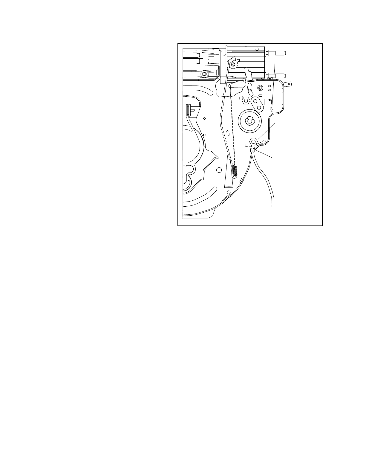
TO REPLACE BRAKE PAD:
1. If equipped with electric starter, locate wire routing
through blower housing. Compress the grommet
and pull out of the blower housing. Carefully slide
wires through the slot. DO NOT cut the wire
insulation on the blower housing.
2. Remove flywheel (see flywheel removal.)
3. Remove pad lever “E” clip. Lift pad lever, and
unhook spring and link.
4. Attach the link to the new pad lever, install pad lever
and “E” clip.
5. Attach spring to lever first. Use a needle nose pliers
to hook the spring into the baffle.
PAD LEVER "E" CLIP
KEYSWITCH CONTROL
IGNITION SHORT-OUT SWITCH
CHARGING RECTIFIER
STARTER MOTOR
(INTERNALLY GROUNDED)
STARTER INTERLOCK SWITCH
ELECTRIC STARTER LEAD
HEAVY DUTY SWITCH
BATTERY
(12 VOLT)
RED #12
A.W. G.
IGNITION SHORT-OUT LEAD
BATTERY GROUND
IGNITION SHORT-OUT LEAD
BATTERY GROUND
IGNITION SHORT-OUT LEAD
ALTERNATOR LEAD
ALTERNATOR LEAD
BLACK #12
A.W. G.
VIEW A-A
IGNITION
SHORT-OUT
LEAD #13
(OPTIONAL)
RED #12 A.W .G.
RED #18 A.W .G.
A.W. G.
ALTERNATOR
LEAD
ELECTRIC
STARTER
LEAD
BRAKE LEVER "E"
LONG HOOK
SHORT HOOK
NOTE: It is important to attach the pad lever spring
with the short hook on the pad lever and the long hook
to the blower housing baffle.
ALL GROUND CONNECTIONS MUST BE CLEANED TO A BRIGHT FINISH.
21
Page 25

BRAKE LEVER
Not For Resale
www.SmallEngineDiscount.com
CONTROL SPRING
TO REPLACE BRAKE CONTROL LEVER:
1. Mark hole that spring is installed into baffle.
2. Remove “E” clip from brake lever shaft.
3. Lift brake control lever and unhook link. Replace
with new lever and reassemble in reverse order.
CONTROL SWITCH. The brake lever must close the
switch before the starter can be engaged.
Disconnect battery from circuit before making check.
Engines equipped with an electric starter have a control
switch that is attached to the brake lever. The brake
lever must close the switch before the starter can be
engaged.
CHECKING THE CONTROL SWITCH. Disconnect the
battery from the circuit. Use a continuity light or meter
to check control switch operation. Disconnect the wire
harness at the engine. Attach one continuity light lead
to the electric starter lead (see illustration on previous
page.) Attach the other continuity light lead to the battery
ground lead. With leads attached, press the control
switch lever and the continuity light should go on, if not
replace switch.
4. Replacement springs must be the same size and
color.
5. Be sure control lever spring is in proper hole in
blower housing baffle before reassembly.
When removing the brake lever with a reverse pull brake,
the pad lever must be removed to unhook the brake
link from the brake lever.
BRAKE LEVER CONTROL LINK ATTACHMENT
BRAKE LEVER END
PAD LEVER END
CHECK
CONTINUITY
ELECTRIC STARTER
CONTROL SWITCH
22
Page 26

Chapter 6
Not For Resale
www.SmallEngineDiscount.com
ALTERNATOR
ALTERNATOR
LAMINATION SCREWS
ALTERNATOR
COIL
ALTERNATOR. The 350 Milliamp charging system
consists of a single alternator coil mounted to one side
of the solid state module.
NOTE: This charging system is designed to maintain a
charged battery. Most O.E.M.'s supply a trickle charger,
which should be used before and after off season
storage. Then this system will maintain the charge level
under normal use conditions.
Do not operate engine with charging system
disconnected. Damage to diode may occur.
CHECKING THE SYSTEM. Connect voltmeter at the
battery (should read battery voltage). The battery MUST
BE IN CIRCUIT for test to perform properly. Next, start
engine -voltage should read higher than when engine
is off. If there is a change upward in voltage, the charging
system is working. If there is no change in voltage, the
alternator should be replaced.
NOTE: Set volt/ohm meter to 0-20 volt D.C. scale for
test.
SOLID STATE MODULE
IGNITION COIL
LAMINATION SCREW
TROUBLESHOOTING ELECTRIC START ENGINES.
Following is a list of possible problems and causes.
DEAD BATTERY
Extended storage without charging
Excessive cranking
Faulty starter
Faulty wiring
Faulty alternator
Faulty battery
BATTERY O.K., ENGINE WON‘T CRANK
Brake cable defective
Faulty starter switch
Poor electrical connections
Faulty starter. See starter section
ENGINE CRANKS SLOWLY
Weak or discharged battery
Faulty starter
TROUBLESHOOTING FOR BOTH MECHANICAL
AND ELECTRIC START SYSTEMS
IF ENGINE PULLS OR CRANKS HARD
Excessive engine drag due to obstructions under
deck.
Mower traction drive misadjusted
Valve clearance too wide
Compression release not functioning
Compliance brake is still applied
Maximum compression should be 90 PSI. If
compression is higher, de-carbon the valve seat and
head area and check valve clearances. Exhaust valve
clearance may be set as low as .004'’ if necessary to
gain more compression relief. If compression is still
above 90 PSI, check compression relief part of
camshaft.
23
Page 27

Chapter 7
Not For Resale
www.SmallEngineDiscount.com
IGNITION
SOLID STATE IGNITION. Tecumseh’s solid state
capacitor discharge ignition (CDI) is an all electronic
ignition system and is encapsulated in epoxy for
protection against dirt and moisture.
SOLID STATE IGNITION OPERATION. As the magnets
in the flywheel rotate past the charge coil, electrical
energy is produced in the module. This energy is
transferred to a capacitor where it is stored until it is
needed to fire the spark plug.
The magnet continues rotating past a trigger coil where
a low voltage signal is produced and closes an electronic
switch (SCR).
The energy which was stored in the capacitor is now
transferred through the switch (SCR) to a transformer
where the voltage is increased from 200 volts to 25,000
volts. This voltage is transferred by means of the high
tension lead to the spark plug, where it arcs across the
electrode of the spark plug and ignites the fuel-air
mixture.
SPARK PLUG SERVICE. Spark plugs should be
replaced periodically. Check electrode gap with wire
feeler gauge and adjust gap to .030". Replace if
electrode is pitted, burned or the porcelain is cracked.
Refer to Master Parts Manual for correct replacement
number. Use a spark plug tester to check for spark.
The proper air gap setting between magnets and the
laminations on CDI systems is .0125'’. Place .0125'’
gauge, Part No. 670297 between the magnets and
laminations and tighten mounting screws to a torque of
30-40 inch pounds. Recheck gap setting to make certain
there is proper clearance between the magnets and
laminations. NOTE: Due to variations between pole
shoes, air gap may vary from .005/.020'’ when flywheel
is rotated. There is no further timing adjustment on
external lamination systems.
IGNITION TIMING. The flywheel key is what times the
ignition for the engine. If this key is partially sheared
from striking an object with the blade. The timing and
engine performance could be affected. The key should
be inspected if a performance problem exists.
If spark plug fouls frequently, check for the following
conditions:
1. Incorrect spark plug
2. Poor grade gasoline
3. Breather plugged
4. Oil level too high
5. Engine using excessive oil
6. Clogged air cleaner
24
Page 28
Chapter 8
Not For Resale
www.SmallEngineDiscount.com
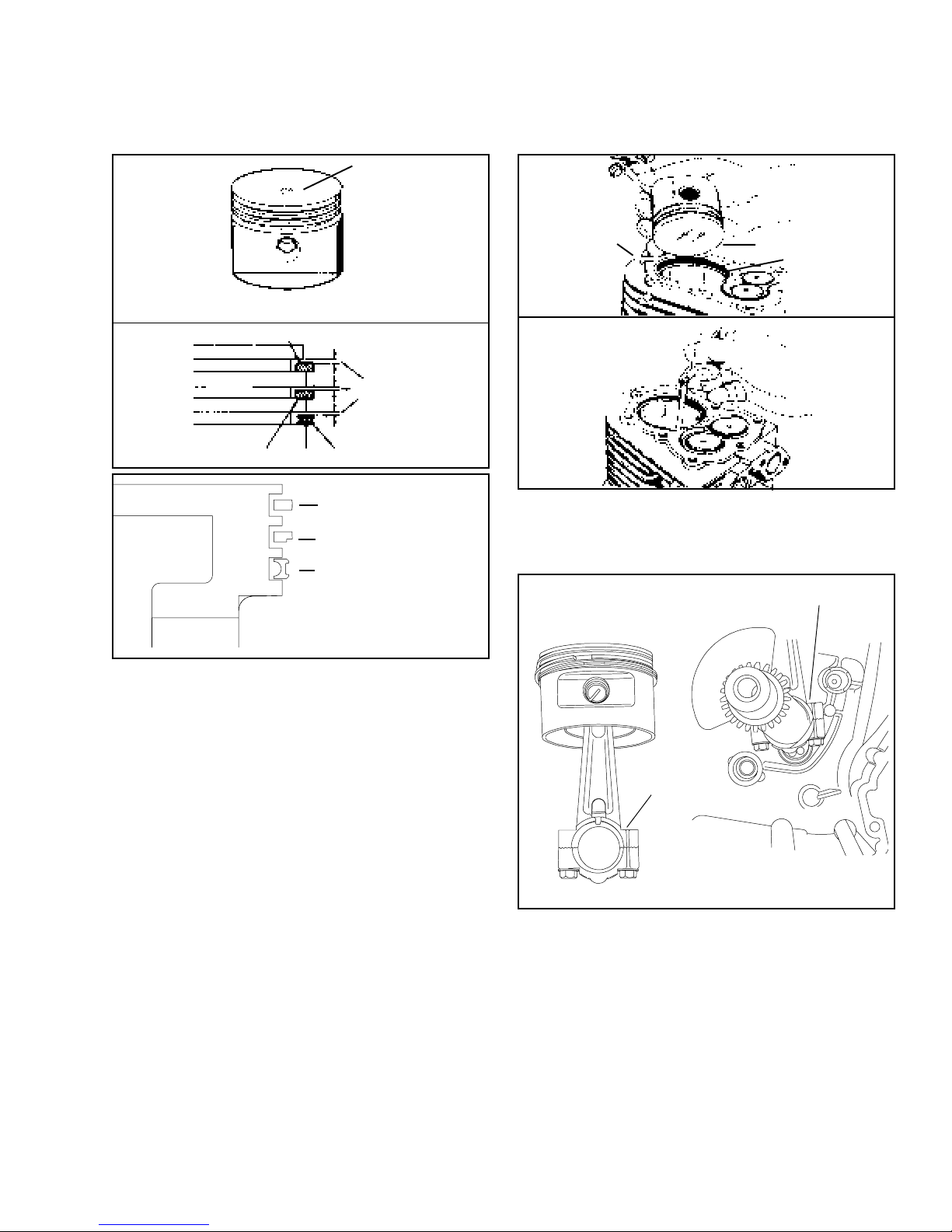
PISTON, RINGS AND CONNECTING ROD
INDICATES .010
OVERSIZE PISTON
PISTON MEASUREMENTS ARE TAKEN AT
BOTTOM OF SKIRT 900 FROM WRIST PIN HOLE
1ST COMPRESSION RING
SIDE CLEARANCE
2ND COMPRESSION RING
NOTE: EMISSION COMPLIANT
VLV USES THIS RING PACKAGE
PISTON. Before removing piston, clean any carbon from
the top of the cylinder bore to prevent ring breakage
when removing the piston. Push the rod and piston out
through the top of the cylinder.
3RD OIL CONTROL RING
BARREL FACED TOP RING
SCRAPER RING
OIL CONTROL RING
CYLINDER
CONNECTING RODS. Match marks on connecting
rods must always align and must face outward toward
the mechanic when installed in an engine.
PISTON
PISTON RING
MATCH MARKS
Oversize pistons are identified by the size imprinted on
the piston as shown. Check the piston for wear by
measuring at the bottom of the skirt 90o from the wrist
pin hole. Clean the carbon from the piston ring grooves,
install new rings and measure side clearance.
Tolerances are listed in the table of specifications (page
40).
Replace rings in sets and always stagger ring gaps.
When in stalling new rings, deglaze cylinder wall, using
a commercially available deglazing tool.
Use a ring expander to remove and replace rings. Do
not spread the rings too wide or breakage will result.
The top compression ring will have a chamfer on the
inside edge. The ring must be installed with the chamfer
up.
To check ring end gap, place ring squarely in center of
ring travel area. Using the piston to push the ring down
into the cylinder at least one inch.
Check ring gap on new ring to determine if cylinder
should be rebored to take oversize parts. See Table of
Specifications (page 40).
MATCH MARKS
A new piston can be installed on to the connecting rod
in either direction.
If the old piston is reused, install the piston to the
connecting rod so that the piston will be in the same
position when reinstalled in the engine.
If it is necessary to replace the connecting rod be sure
to mark the valve side of the piston.
25
Page 29

Chapter 9
Not For Resale
www.SmallEngineDiscount.com
CYLINDERS AND CYLINDER HEADS
CYLINDER SERVICE. Check cylinder for dirty, broken
or cracked fins, worn or scored bearings or scored
cylinder bore surface, and warped head mounting
surface.
If cylinder bore is worn more than .005'’ oversize, out-of
round or scored, it should be replaced or rebored to
.010 or .020 oversize. In some cases engines are built
with an oversize cylinder; in these instances they are
identified with the oversize value imprinted on the
cylinder as pictured. Service pistons have the oversized
valve marked on the dome.
INDICATES .010 OVERSIZE PISTON
.010
CYLINDER HEADS. Check cylinder heads for warpage
by placing on a flat surface. If the cylinder head gasket
surface is warped in excess of .005 inches (.13 mm),
replace head. Always replace head gasket and torque
head bolts in 50 inch lb. increments in the numbered
sequence to a torque of 180-220 inch lbs. (20.3 - 25
nm)
TORQUE IN NUMERICAL ORDER
4
7
2
1
5
6
3
REBORING CYLINDER. To rebore cylinder we
recommend using a reputable machine shop or service
center.
Then hone the cylinder with 380 grit stone to obtain a
good cross hatch pattern for proper ring seating.
Clean cylinder with soap and water, and dry thoroughly.
Replace piston and piston rings with correct oversize
parts as indicated in parts manual.
26
Page 30

Chapter 10
Not For Resale
www.SmallEngineDiscount.com
CRANKSHAFTS, CAMSHAFTS
AND LUBRICATION
CRANKSHAFTS. Inspect crankshaft for worn,
scratched or damaged bearing surfaces, out-of-round
or flat spots on the journal area, or a bent P.T.O. end.
CAUTION: Never try to straighten a bent crankshaft.
When installing a crankshaft, lubricate all bearing
surfaces and use oil seal protector part no. 670327.
CRANKSHAFT TIMING MARK
The crankshaft has a pressed on timing gear. This gear
has a small dimple punched on one of the teeth on this
gear. This dimple is a timing mark. With the crankpin
at top dead center, the timing mark should be in the
2:30 position.
2:30
The camshaft has an aligning mark in line with the timing
hole on the camshaft gear. Line this mark up with the
dimple on the crankshaft gear.
Timing marks on crankshaft gear and camshaft gear
must be aligned for proper valve timing.
CAMSHAFT REMOVAL:
Align timing marks to relieve valve train pressure. Lift
out cam.
CRANKSHAFT
COUNTERWEIGHT
RELIEF
COMPRESSION RELEASE
MECHANISM
The camshaft has a mechanical compression release
mechanism. A pin which runs through both cam lobes
extends past the exhaust lobe and lifts the valve to
relieve compression for easier starting. When the engine
starts, centrifugal force moves the flyweight outward,
moving the pin below the lobe, allowing full compression.
The compression release mechanism is nonserviceable
(replace camshaft assy. if damaged or worn.)
The camshaft has been relieved in the intake lobe area.
This change was made to accommodate added
crankshaft counterweight material for improved engine
balance.
27
Page 31
LUBRICATION SYSTEM:
Not For Resale
www.SmallEngineDiscount.com
All Tecumseh Vertical shaft 4-cycle engines use a
positive displacement plunger oil pump to pump oil from
the crankcase, up through the camshaft to a passage
in the breather box to the top crankshaft main bearing,
and ultra balance bearings.
Oil is pressure sprayed out of a small hole between the
crankshaft and ultra-balance bearing, to lubricate the
connecting rod journal area. If a heavy leakage is noted
from the breather cover check for plugged mist hole.
FROM CAMSHAFT
CHAMFER UP
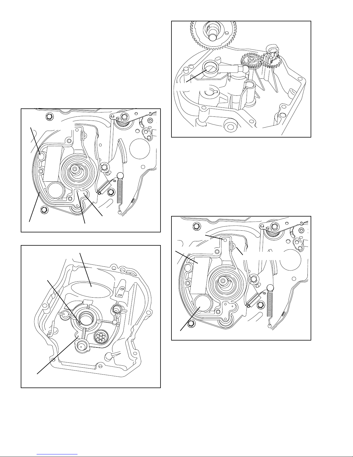
OIL PUMP. An eccentric on the camshaft works the
plunger in the barrel back and forth, forcing oil up the
center of the camshaft. A ball on the end of the plunger
locates in a recess in the flange cover. When installing
oil pump, make certain the chamfered side of the pump
barrel faces the camshaft, and the plunger ball seats in
the recess of the flange cover.
OIL PASSAGE
OIL DRAIN
HOLE
OIL MIST HOLE
MAIN BEARING LUBE HOLE
BREATHER OIL RETURN HOLE
This engine has a top mounted integral breather.
OIL RETURN
FILTER ELEMENT
BREATHER TUBE
BREATHER CHECK VALVE
SPRAY MIST HOLE
28
Page 32

The breather compartment is located under the flywheel.
Not For Resale
www.SmallEngineDiscount.com
A check valve allows excess crankcase pressure to be
vented through the element and out the breather tube.
The breather tube is connected to the air cleaner body.
When reassembling the breather, DO NOT pinch the
filter element under the breather cover or leak may
occur.
OIL RETURN HOLE
BREATHER TUBE
CONNECTION
NOTE: ALWAYS RECONNECT THE BREATHER TUBE
Condensed oil vapors are returned to the crankcase by
means of the oil return hole. The oil return hole is opened
and closed in the cylinder by the piston.
The breather filter element can be cleaned using solvent.
When reinstalling the check valve, apply oil to aid in
assembly. A new breather valve body can be pressed
into the block to replace a damaged breather valve body.
29
Page 33

Chapter 11
Not For Resale
www.SmallEngineDiscount.com
VALVES, LIFTERS, SPRING & VALVE SEATS
VALVES. Valves must be in good condition, proper
sealing and proper gap must be maintained for full
power, easy starting and efficient operation.
VALVE REMOVAL. To remove valves, use a
commercially available valve spring compressor. Move
the lower cap, so it will slip off the end of the valve.
Clean all parts and remove carbon from valve heads
and stems. If valves are in usable condition, grind the
valve faces to a 45o angle. Replace valves if they are
damaged, distorted or if the margin is ground to less
than 1/32'’.
MARGIN
o
45
1/32" MINIMUM
DIMENSION
STEM
FACE
BOTTOM
NARROWING
CUTTER
o
15
Ù
Ù
o
60
SEAT
BOTTOM
NARROWING
Second, use the 31o cutter to clean and narrow the seat
from the top toward the center.
o
TOP
NARROWING
CUTTER
46
31
Ù
o
Ù
Ú
Ú
Ú
SEAT
VALVE SEATS. Valve seats are not replaceable. If
they are burned or pitted, they can be reground using a
grinding stone or valve seat cutter.
EXHAUST
VALVE
o
46
INTAKE
VALVE
SEE SPECIFICATIONS
SECTION FOR DIMENSIONS
The recommended procedure to properly cut a valve
seat is to use the Neway Valve Cutting System, which
consists of three different degree-cutters. First, use the
60o cutter to clean and narrow the seat from the bottom
toward the center.
Seats are ground at an angle of 46o, to a width of 3/64'’.
o
31
SEAL CUTTER
3/64"
Ú
SEAT
Valves are not identical. Make sure the valve marked
“EX” or “X” is installed in the exhaust valve location,
and the valve marked “I” is installed in the intake valve
location. If the valves are unmarked, the nonmagnetic
valve is installed in the exhaust valve location.
46
Ù
Ù
o
30
Page 34

FACE
Not For Resale
www.SmallEngineDiscount.com
WRONG
RIGHT
VALVE ADJUSTMENT. Clearance between the valve
stem and lifter must be set to the recommended
specifications when the engine is cold (see page 40).
Check these clearances with the piston T.D.C. on the
compression stroke. Grind end of valve stem with a
valve grinder, or use a “V” block to hold the valve square
on grinding wheel, grinding to the proper .004" to .008”
clearance.
NOTE: Some emissionized engines use intake valve
stem seals to maintain proper oil control and emission
compliance, they must be replaced if the valve has been
removed.
VALVE LIFTERS. It is a good practice not to
interchange lifters, even though they are identical, once
a wear pattern has been established.
OVERSIZE VALVE GUIDES. Valve guides are
permanently installed in the cylinder. If they become
worn excessively, they can be reamed oversized to
accommodate a 1/32'’ over size valve stem.
Ream guides with a straight shanked hand reamer or
low speed drill press. Refer to Table of Specifications
to determine correct oversize dimension. Reamers are
available through your Tecumseh parts suppliers. See
Tool Section for correct part numbers.
After oversizing valve guides the seats must be recut to
align with the valve guides.
VALVE INSTALLATION. To reinstall valves, position
valve caps and spring in the valve compartment. Install
valves in guides with valve marked “I” in the intake port.
The valve stem must pass through the spring. The valve
spring cap should sit around the valve lifter exposed
end. Use a valve spring compressor to compress the
valve spring. Position the valve spring cap onto the
valve stem and release valve spring tension to lock cap
in place.
31
Page 35
Chapter 12
Not For Resale
www.SmallEngineDiscount.com
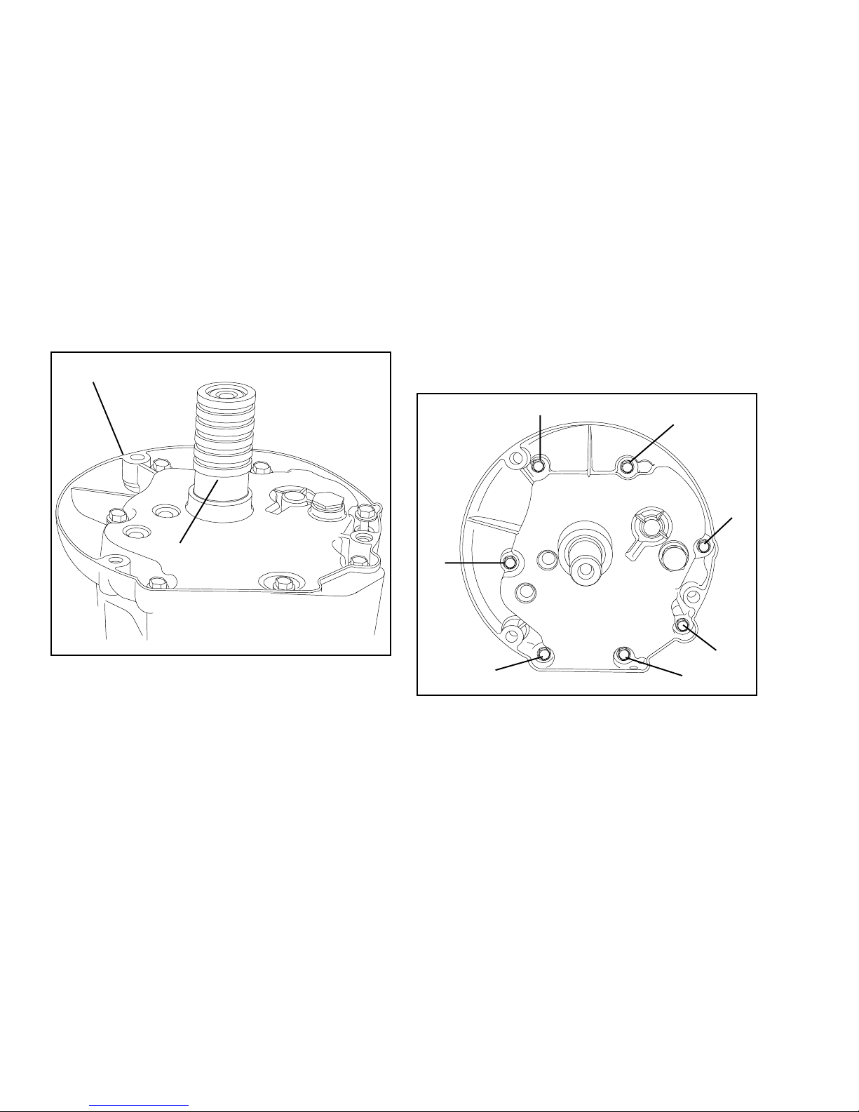
OIL SEAL SERVICE AND MOUNTING FLANGE
OIL SEAL SERVICE. Drain oil from crankcase. If the
crankshaft end is rusty or pitted, polish the crankshaft
with emery cloth so it will not damage the bearings when
the cover is removed.
Remove mounting bolts and slide seal protector-driver
tool (Part No. 670327) into the oil seal. If necessary,
tap edge of flange or cover lightly with a soft hammer to
remove cover.
Clean and inspect the cover for wear and scoring of
bearings. Inspect crankshaft bearings. Replace any
worn or damaged parts.
MOUNTING FLANGE
SEAL PROTECTOR DRIVER
If crankshaft is out of engine, remove old oil seals by
tapping them out with a screwdriver or punch from the
inside. To remove a seal with the crankshaft in the
engine, insert a screwdriver between the seal and the
crankshaft and pry the seal out.
TO REPLACE SEALS: Lubricate the outside of the new
oil seal with oil prior to installation. Use seal driverprotector tool Part No. 670327. Place oil seal over the
driver-protector and place over crankshaft, driving it into
position using universal driver No. 670272. The seal
will automatically be driven into the proper depth.
Torque flange bolts in numerical order as shown in
illustration. See page 41 for torque specifications.
3
5
7
1
2
6
4
32
Page 36

Chapter 13
Not For Resale
www.SmallEngineDiscount.com
TROUBLESHOOTING
A. COMMON TROUBLES AND REMEDIES.
The following charts list the most common troubles
experienced with gasoline engines. Possible causes of
trouble are given along with probable remedy.
B. 4-CYCLE ENGINE TROUBLESHOOTING CHART
Cause Remedy and Reference
ENGINE FAILS TO START OR STARTS WITH DIFFICULTY
No fuel in tank Fill tank with clean, fresh fuel.
Shut-off valve closed Open valve.
Obstructed fuel line Clean fuel screen and line. If necessary, remove and clean
carburetor.
Incorrect Timing Flywheel key has sheared or partially sheared. Replace key.
Tank cap vent obstructed Clean the vent or replace the cap.
Water in fuel Drain tank. Clean carburetor and fuel lines. Dry spark plug
points. Fill tank with clean, fresh fuel.
Engine flooded Close fuel shut-off, if so equipped, and pull starter until engine
starts. Reopen fuel shut-off for normal fuel flow.
Loose or defective ignition wiring Check ignition wiring for shorts or grounds; repair if
necessary.
Spark plug fouled Replace spark plug.
Spark plug porcelain cracked Replace spark plug.
Poor Compression Overhaul engine.
No spark at plug Check ignition air gap. If air gap is correct and there is no
spark at plug replace ignition.
Electric starter does not crank engine See 12 volt starter troubleshooting chart.
ENGINE KNOCKS
Carbon in combustion chamber Remove cylinder head and clean carbon from head and
piston.
Loose or worn connecting rod Replace connecting rod.
Loose flywheel Check flywheel key and keyway; replace parts if necessary.
Tighten flywheel nut to proper torque.
Worn cylinder Replace cylinder.
Improper ignition timing Flywheel key has sheared or partially sheared. Replace key.
33
Page 37

4-CYCLE ENGINE TROUBLESHOOTING CHART (Cont.)
Not For Resale
www.SmallEngineDiscount.com
Cause Remedy and Reference
ENGINE MISSES UNDER LOAD
Spark plug fouled Replace spark plug.
Spark plug porcelain cracked Replace spark plug.
Improper spark plug gap Regap spark plug.
Improper valve clearance Adjust valve clearance to recommended specifications.
Weak valve spring Replace valve spring.
ENGINE LACKS POWER
Ignition improperly timed Replace flywheel key.
Worn rings Replace rings.
Lack of lubrication Fill crankcase to the proper level.
Air cleaner fouled Service air cleaner.
Valves leaking Grind valves and set to recommended specifications.
ENGINE OVERHEATS
Engine improperly timed Replace flywheel key if sheared.
Air flow obstructed Remove any obstructions from air passages in shrouds.
Cooling fins clogged Clean cooling fins.
Excessive load on engine Check operation of associated equipment. Reduce
excessive load.
Carbon in combustion chamber Remove cylinder head and clean carbon from head and
piston.
Lack of lubrication Fill crankcase to proper level.
ENGINE SURGES OR RUNS UNEVENLY
Fuel tank cap vent hole clogged Open vent hole.
Governor parts sticking or binding Clean, and if necessary repair governor parts.
Carburetor throttle linkage or throttle shaft Clean, lubricate, or adjust linkage and deburr throttle shaft
and/or butterfly binding or sticking or butterfly.
Intermittent spark at spark plug Disconnect ignition cut-off wire at the engine. Crank
engine. If spark, check ignition switch, safety switch and
interlock switch. If no spark, check ignition air gap. Check
wires for poor connections, cuts or breaks.
Dirty carburetor Clean carburetor.
ENGINE VIBRATES EXCESSIVELY
Engine not securely mounted Tighten loose mounting bolts.
Bent crankshaft Replace crankshaft.
Associated equipment out of balance Check associated equipment.
34
Page 38

4-CYCLE ENGINE TROUBLESHOOTING CHART (Cont.)
Not For Resale
www.SmallEngineDiscount.com
Cause Remedy and Reference
ENGINE USES EXCESSIVE AMOUNT OF OIL
Engine speed too fast. Using tachometer adjust engine RPM to spec.
Oil level too high. To check level turn dipstick cap tightly into receptacle for
accurate level reading.
Oil filler cap loose or gasket damaged causing Replace ring gasket under cap and tighten tube securely.
spillage.
Breather mechanism damaged or dirty causing Replace breather assembly.
leakage.
Drain hole in breather box clogged causing oil to Clean hole with wire to allow oil to return to crankcase.
spill out of breather.
Gaskets damaged or gasket surfaces nicked Clean and smooth gasket surfaces. Always use new
causing oil to leak out. gaskets.
Valve guides worn excessively thus passing oil Ream valve guide oversize and install 1/32'’ oversize valve
into combustion chamber. and new valve seal if equipped.
Cylinder wall worn or glazed, allowing oil to Bore cylinder for oversized piston & rings.
bypass rings into combustion chamber.
Piston rings and grooves worn excessively. Reinstall new rings and check land clearance and correct
as necessary.
Piston fit undersized. Measure and replace as necessary.
Piston oil control ring return holes clogged. Remove oil control ring and clean return holes.
Oil passages obstructed. Clean out all oil passages.
Breather tube not connected to air cleaner. Reconnect tube.
Using 10W30 oil under high load/high temperature Replace with SAE 30 oil.
conditions.
OIL SEAL LEAKS
Crankcase breather plugged. Clean or replace breather.
Seal/Main brg drain hole plugged. Clean out hole.
Old seal hardened and worn. Replace seal.
Crankshaft seal contact surface is worn undersize Check crankshaft size and replace if worn excessively.
causing seal to leak.
Crankshaft bearing under seal is worn excessively, Check crankshaft bearings for wear and replace if
causing crankshaft to wobble in oil seal. necessary.
Seal outside seat in cylinder or side cover is Visually check seal receptacle for nicks and damage.
damaged, allowing oil to seep around outer Replace P.T.O. cylinder cover, or small cylinder cover on
edge of seal. the magneto end if necessary.
35
Page 39

4-CYCLE ENGINE TROUBLESHOOTING CHART (Cont.)
Not For Resale
www.SmallEngineDiscount.com
Cause Remedy and Reference
OIL SEAL LEAKS
New seal installed without correct seal driver and Replace with new seal, using proper tools and methods.
not seating squarely in cavity.
New seal damaged upon installation. Use proper seal protector tools and methods for installing
another new seal.
Bent crankshaft causing seal to leak. Check crankshaft for straightness and replace if
necessary.
Oil seal driven too far into cavity. Remove seal and replace with new seal, using the correct
driver tool and procedures.
BREATHER PASSING OIL
Engine speed too fast. Use tachometer to adjust correct RPM.
Loose oil fill cap or gasket damaged or missing. Install new ring gasket under cap and tighten securely.
Oil level too high. Check oil level Turn dipstick cap tightly into receptacle for
accurate level reading. DO NOT fill above full mark.
Breather mechanism damaged. Replace umbrella valve/seat in Vector engine and TVS
engines.
Breather mechanism dirty. Clean thoroughly in solvent. Use new gaskets when
reinstalling unit.
Drain hole in breather box clogged. Clean hole with wire to allow oil to return to crankcase.
Breather mechanism installed upside down. Small oil drain holes must be down to drain oil from
mechanism.
Breather mechanism loose or gaskets leaking. Install new gaskets and tighten securely.
Damaged or worn oil seals on end of crankshaft. Replace seals.
Rings not properly seated. Check for worn, or out of round cylinder. Replace rings.
Break in new rings with engine working under a varying
load. Rings must be seated under high compression, or
in other words, under varied load conditions.
Breather assembly not assembled correctly. See section on Breather Assembly.
Cylinder cover gasket leaking. Replace cover gasket.
36
Page 40

C. TROUBLESHOOTING CARBURETION.
Not For Resale
www.SmallEngineDiscount.com
POINTS TO CHECK FOR CARBURETOR MALFUNCTION
TROUBLE CORRECTIONS
Engine will not start 1, 2, 3, 4, 5, 6, 8, 14, 15, 17
Engine will not accelerate 2, 3, 17
Engine hunts (at idle or high speed) 3, 4, 8, 9, 14
Engine will not idle 4, 8, 9, 14
Engine lacks power at high speed 2, 3, 6, 8, 17
Carburetor floods 4, 7, 16
Carburetor leaks 6, 7
Engine overspeeds 8, 9, 14, 15
Idle speed is excessive 8, 9, 14, 15
Choke does not open fully 8, 9, 15
Engine starves for fuel at high speed (leans out) 1, 3, 4, 6, 15, 16, 17
Carburetor runs rich with main adjustment needle shut off 7, 16
Performance unsatisfactory after being serviced. 1, 2, 3, 4, 5, 6, 7, 8, 9, 15, 16, 17
1. Open fuel-shut off valve at fuel tank—Fill tank with
fuel.
2. Check ignition, spark plug.
3. Clean air cleaner—Service as required.
4. Dirt or restriction in fuel system—Clean tank and
fuel strainers, check for kinks or sharp bends.
5. Check for stale fuel or water in fuel - - Fill with fresh
fuel.
6. Examine fuel line and pick-up for sealing at fittings.
7. Check and clean atmospheric vent holes.
8. Examine throttle for binding or excessive play- Remove all dirt or paint, replace shaft.
9. Examine throttle return spring for operation.
10. Check for bent throttle plate.
11. Adjust control cable or linkage, to assure carburetor
control.
12. Clean carburetor after removing all nonmetallic parts
that are serviceable. Trace all passages.
13. Check inlet needle and seat for condition and proper
installation.
14. Check sealing of welch plugs, and gaskets.
15. Adjust governor linkage.
16. Check float shaft for wear and float for leaks or
dents.
17. Check flywheel key for damage.
37
Page 41

D. TROUBLESHOOTING 12 VOLT STARTERS
Not For Resale
www.SmallEngineDiscount.com
PROBLEM PROBABLE CAUSE FIX
Does not function Weak or dead battery Check charge and/or replace battery.
Corroded battery terminals and/or Clean terminals and/or connections.
electrical connections
Brushes sticking Free brushes. Replace worn brushes and
those which have come in contact with
grease and oil.
Dirty or oily commutator Clean and dress commutator.
Armature binding or bent Free armature and adjust end play, replace
armature, or replace starter.
Open or shorted armature Replace armature.
Shorted, open or grounded field coil Repair or replace housing.
Loose or faulty electrical connections Correct.
Load on engine Disengage brake.
Electric starter cranks, but no spark Disconnect ignition cut-off wire at the engine.
at spark plug Crank engine. If spark at spark plug, ignition
switch, safety switch is in operative. If no
spark, check air gap. Check wires for poor
connections, cuts or breaks.
Electric starter does not crank engine Remove starter wire. Use a jumper battery
and cables and attach directly to starter wire.
If starter cranks engine the starter is okay,
check solenoid, starter switches, safety
switches and interlock switch. Check wires
for poor connections, cuts or breaks.
Electric starter cranks, but engine Check flywheel ring gear for broken teeth.
does not turn over. Replace flywheel if necessary.
Low RPM Unit controls engaged Insure all unit controls are in neutral or
disengaged.
Worn bearings in cap assemblies Clean bearings or replace cap assemblies.
Bent armature Replace armature.
Binding armature Free up armature. Adjust armature end play.
Brushes not seated properly Correct.
Weak or annealed brush springs Replace springs.
Incorrect engine oil Ensure the correct weight of oil is being
used.
Dirty armature commutator Clean commutator.
Shorted or open armature Replace armature.
Loose or faulty electrical connections Correct.
in motor
38
Page 42

TROUBLESHOOTING 12 VOLT STARTERS (Cont.)
Not For Resale
www.SmallEngineDiscount.com
PROBLEM PROBABLE CAUSE FIX
Motor stalls under load Shorted or open armature Replace armature.
Shorted field coil Correct, or replace housing assembly.
Intermittent operation Brushes binding in holders Free up brushes. Replace worn brushes
and those which have come in contact with
grease and oil.
Dirty or oily commutator Clean and dress commutator.
Loose or faulty electrical Correct
connections
Open armature Replace armature and interlock switch.
Break in electrical circuit Disconnect ignition cut-off wire at the
engine. Crank engine, if spark, check
ignition switch, safety switch and interlock
switch. Check wires for poor connections,
cuts or breaks.
Sluggish disengagement Dirt and oil on assembly and Clean drive assembly and armature shaft
of the drive assembly armature shaft and relubricate shaft splines.
pinion gear
Bent armature Replace armature.
39
Page 43

Chapter 14
Not For Resale
www.SmallEngineDiscount.com
ENGINE SPECIFICATIONS
VLV40 VLV50, 55, 60, 65
Displacement 11.19 183.4 cc 12.6 207 cc
Stroke 2.047 51.993 mm 2.047 51.993 mm
Bore 2.6390 67.031 mm 2.796 71.018 mm
Air Gap Dimension Ignition .0125 .30 mm .0125 .30 mm
Spark plug gap .030 .70 mm .030 .70 mm
Valve Clearance Intake and Exhaust .004 .101 mm .004 .101 mm
Valve Seat Angle 46
Valve Seat Width .047 1.2 mm .047 1.2mm
Valve Guide Oversize Dia. .2807 71.297 mm .2807 71.297 mm
Crankshaft End Play .005 .127 mm .005 .127 mm
Crankpin Journal Dia. 1.0235 25.996 mm 1.0235 25.996 mm
Crankshaft Magneto Main Brg. Dia 1.0242 26.014 mm 1.0242 26.014 mm
Crankshaft P.T.O. Main Brg. Dia 1.0242 26.014 mm 1.0242 26.014 mm
2.6380 2.795 70.993 mm
.008 .203 mm .008 .203 mm
o
.2817 71.551 mm .2817 71.551 mm
.027 .685 mm .027 .685 mm
1.0230 25.984 mm 1.0230 25.984 mm
1.0237 26.001 mm 1.0237 26.001 mm
1.0237 26.001 mm 1.0237 26.001 mm
46
o
Camshaft Bearing Dia. .4980 12.649 mm .4980 12.649 mm
Conn. Rod Dia. Crank Brg. 1.0246 26.024 mm 1.0246 26.024 mm
Piston Diameter 2.6340 66.903 mm 2.6340 66.903 mm
Ring Groove Side Clearance 1st & 2nd Comp. .002 .050 mm .002 .050 mm
Side Clearance (Bot.) Oil .0005 .012 mm .0005 .012 mm
o
Piston Skirt Clearance measured 90
at the bottom of the skirt .006 .152 mm .006 .152 mm
Ring End Gap .007 .177 mm .007 .177 mm
Cylinder Main Brg. Dia 1.0262 26.065 mm 1.0262 26.065 mm
Cylinder Cover/Flange Main Bearing Diameter 1.0262 26.065 mm 1.0262 26.065 mm
from pin .004 .101 mm .004 .101 mm
.4975 12.636 mm .4975 12.636 mm
1.0240 26.009 mm 1.0240 26.009 mm
2.6330 66.878 mm 2.6330 66.878 mm
.005 .127 mm .005 .127 mm
.0035 .088 mm .0035 .088 mm
.020 .508 mm .020 .508 mm
1.0257 26.052 mm 1.0257 26.052 mm
1.0257 26.052 mm 1.0257 26.052 mm
40
Page 44

TORQUE SPECIFICATIONS
Not For Resale
www.SmallEngineDiscount.com
Inch-Lbs. Nm
Governor Rod Clamp to Lever 7-12 1.4 - 1.4
Breather Cover 40-50 4.5 - 5.7
Valve Box Cover 25-35 3.1 - 4.0
Connecting Rod 95-110 10.7 - 12.4
Cylinder Head 180-220 20.3 - 25
Mounting Flange or Cylinder Cover 100-130 11.3 - 14.7
Housing Baffle to Cylinder 80-120 9.0 - 13.6
Solid State Ignition to Cylinder 30-50 3.4 - 5.7
Alternating Coil Assembly to Lamination 25-35 2.8 - 4.0
Flywheel Nut 400-440 45.2 - 49.7
Housing to Baffle 35-45 4.0 - 5.1
Carburetor Stud to Cylinder 50-75 5.7 - 8.5
A/C Hex Nut to Stud 35-45 4.0 - 5.1
Control Face Plate to Baffle 30-40 3.4 - 4.5
Starter Top Mounting 20-30 2.3 - 3.4
Electric Starter to Baffle 25-35 2.8 - 3.9
5/8-18 Plug (Hex Flange) Drain plug 90-150 10.2 - 17.0
Plastic Tank to Housing 12-20 1.4 - 2.3
Threaded Fill Tube (Plastic) 45-65 4.0 - 7.3
Large Diameter Oil Fill Plug Hand Tight
Muffler Mounting (Shoulder Screw) 100-165 11.3 - 18.7
A/C Body & Housing to Baffle 35-45 4.0 - 5.1
Conduit Clip Screw (Throttle Cable) 5-15 .6 - 1.7
Muffler Deflector 10-15 1.1 - 1.7
41
Page 45
Chapter 15
Not For Resale
www.SmallEngineDiscount.com
TRAINING AIDS AND TOOLS
VIDEO PROGRAMS
695015
Carburetor Troubleshooting. Covers identification of
carburetors used on Tecumseh engines and how to
troubleshoot and repair them. VHS only.
695059
Understanding Tecumseh Ignition Systems. A basic
program designed to give the small engine technician
first hand knowledge of Tecumseh ignition systems so
the technician can understand the system and perform
repairs to it. VHS only.
695148
Teardown and reassembly of the 900 series transaxles.
This video will show a complete step-by-step procedure
for teardown and reassembly of the 900, 910 and 920
series transaxles.
695185
Electrical Troubleshooting. This video training program
will assist the small engine technician in the proper
procedures for troubleshooting electrical systems on
outdoor power equipment.
695285
An in-depth look at the 800 series transaxles. Detailing
the teardown and reassembly procedures for the 800,
801 and 820 transaxles.
SPECIAL BOOKLETS
INSTRUCTIONAL GUIDE
692738
Assists in the use and understanding of
the Tecumseh Master Parts Manual.
Illustrates time saving features
incorporated into the manual. Explains
new carburetor parts breakdown format.
4-CYCLE ENGINE FAILURE ANALYSIS
695590
This booklet is designed as a tool for
the average technician to correctly
assess the cause of failure.
42
ELECTRICAL TROUBLESHOOTING BOOKLET
693505A
This booklet contains schematic
drawings of Tecumseh direct current
and alternating current systems and
how to check them when problems
occur.
CARBURETOR TROUBLESHOOTING BOOKLET
695907
This booklet is designed as a quick
reference to carburetion problems and
related repair procedures.
IGNITION SYSTEMS
TROUBLESHOOTING BOOKLET
694903
This booklet contains information on the
identification, possible problems and
related repair procedures of Tecumseh
Ignition Systems.
SPECIAL TOOLS BOOKLET
694862
This booklet depicts all specialty tools
offered by Tecumseh which can be
used on 2 and 4 cycle engines and
Peerless units.
QUICK REFERENCE CHART
BOOKLET
695933
This booklet contains the quick
reference information found on
Tecumseh wall charts.
This booklet is designed to be used
as a work bench quick reference guide
when servicing Tecumseh engines
and motion drive systems.
TESTER BOOKLETS
694529
Test procedures for Tecumseh
electrical components using GrahamLee Tester 31-SM or 31-SMX-H.
694530
Test procedures for Tecumseh
electrical components using Merco-OTronic Tester 9800. (Tests are similar
for 98, 98A and 79.)
Page 46

TOOLS
Not For Resale
www.SmallEngineDiscount.com
TOOL KIT 670195C
Kit contains tools for 2- and 4-cycle engines.
Includes all items on this page but items may be purchased separately.
KNOCK-OFF TOOL
670103
VALVE SPRING COMPRESSOR FOR
OVM, OVXL120-125, OHV11-13
670315A
VALVE SPRING COMPRESSOR
FOR OH ENGINE
KNOCK-OFF TOOL
670169
AIR GAP GAUGE .0125"
670253A
CARBURETOR FLOAT
SETTING TOOL
670297
43
Page 47

FLYWHEEL KNOCK-OFF TOOL
Not For Resale
www.SmallEngineDiscount.com
TORX DRIVERS
Torx 8 670334
Torx 10 670333
Torx 15 670323
Torx 20 670324
No. 670169
VIBRATION TACHOMETER
No. 670156 - Vibration tachometer.
Torx 25 670319
Torx 30 670320
No. 670117 - Ring Expander
No. 670327 - Seal Protector Driver
No. 670339 - E-5 Socket
No. 670283 - Valve Guide Reamer
44
Page 48

Chapter 16
Not For Resale
www.SmallEngineDiscount.com
SEARS CRAFTSMAN
CROSS REFERENCE CHART
143.434112 VLV55-501004
143.434252 VLV55-501008
143.945500 VLV55-501004A
143.956000 VLV60-502003A
143.956002 VLV60-502004A
143.956006 VLV60-502012A
143.966000 VLV60-502015B
143.966006 VLV60-502023B
143.966008 VLV60-502024B
143.966500 VLV65-502501A
143.966502 VLV65-502502A
143.966504 VLV65-502503A
143.966506 VLV65-502504A
143.966508 VLV65-502505A
143.976000 VLV60-502015C
45
Page 49

DECIMAL/FRACTION CONVERSIONS
Not For Resale
www.SmallEngineDiscount.com
.016 = 1/64
.031 = 1/32
.047 = 3/64
.063 = 1/16
.078 = 5/64
.094 = 3/32
.109 = 7/64
.125 = 1/8
.141 = 9/64
.156 = 5/32
.172 = 11/64
.188 = 3/16
.203 = 13/64
.219 = 7/32
.234 = 15/64
.25 = 1/4
.516 = 33/64
.531 = 17/32
.547 = 35/64
.563 = 9/16
.578 = 37/64
.594 = 19/32
.609 = 39/64
.625 = 5/8
.641 = 41/64
.656 = 21/32
.672 = 43/64
.688 = 11/16
.703 = 45/64
.719 = 23/32
.734 = 47/64
.75 = 3/4
.266 = 17/64
.281 = 9/32
.297 = 19/64
.312 = 5/16
.328 = 21/64
.344 = 11/32
.359 = 23/64
.375 = 3/8
.391 = 25/64
.406 = 13/32
.422 = 27/64
.438 = 7/16
.453 = 29/64
.469 = 15/32
.484 = 31/64
.50 = 1/2
.766 = 49/64
.781 = 25/32
.797 = 51/64
.813 = 13/16
.828 = 53/64
.844 = 27/32
.859 = 55/64
.875 = 7/8
.891 = 57/64
.906 = 29/32
.922 = 59/64
.938 = 15/16
.953 = 61/64
.969 = 31/32
.984 = 63/64
46
 Loading...