

Page 1

REPAIR PARTS MANUAL
MODEL NO. MI11CRD (MI1192RBA)
Lawn Tractor
Page 2

HOW TO USE THIS MANUAL
This manual is designed to provide the customer with a means to identify the parts on his/her tractor
when ordering repair parts. The illustrations may or may not represent the actual assemblies; therefore,
it is not recommended to use this manual as a guide to assemble or disassemble the tractor. Some
hardware and parts are drawn larger in order to more readily identify them.
Each tractor has its own model number.
The model number for your tractor can be found on the fender under the seat.
When ordering parts, always give the following information:
• Product - “Tractor”
• Model Number - “
• Part Number
• Part Description
MI11CRD (MI1192RBA)
”
TABLE OF CONTENTS
SCHEMATIC ................................................................................................................ 3
ELECTRICAL............................................................................................................4-5
CHASSIS...................................................................................................................6-7
DRIVE........................................................................................................................8-9
STEERING ............................................................................................................10-11
SEAT ..........................................................................................................................12
DECALS.....................................................................................................................13
ENGINE.................................................................................................................14-15
MOWER LIFT........................................................................................................16-17
MOWER DECK .....................................................................................................18-19
BAGGER ...............................................................................................................20-21
2
Page 3
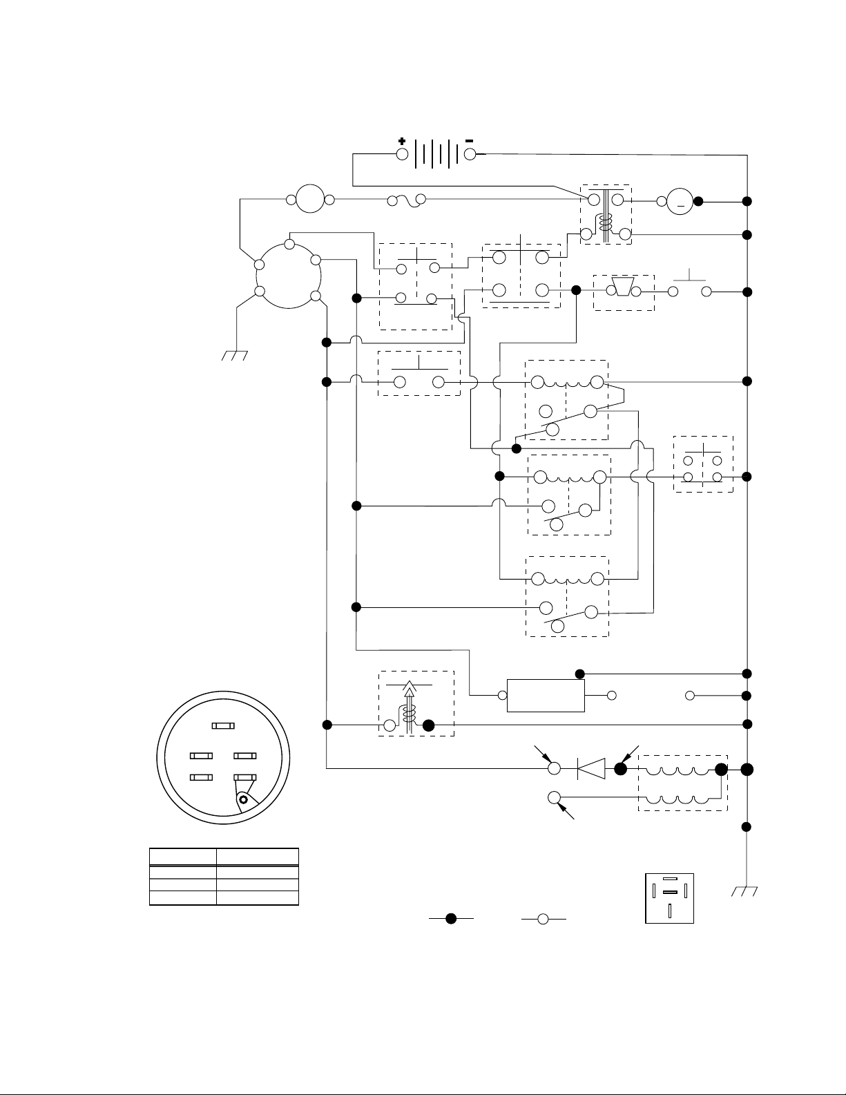
TRACTOR- -MODEL NO. MI11CRD (MI1192RBA), PRODUCT NO. 964 77 75-00
SCHEMATIC
12VDC
BLACK
RED
B
G
AMMETER
(OPTIONAL)
A
WHITE
S
M
L
GREEN
RED
FUSE
BLACK
CLUTCH / BRAKE
(PEDAL UP)
GREEN
SEAT SWITCH
(NOT OCCUPIED)
BATTERY
BLACK
RED
ATT'MENT CLUTCH
(CLUTCH OFF)
STARTER
SOLENOID
FBI BUZZER
OPERATOR PRESENCE
RELAY
85 86
87
30
87A
85 86
87
30
87A
BAGGER RELAY
85 86
BLACK
STARTER
M
BLACK
FBI
SWITCH
BAGGER
INTERLOCK
(NO BAG,
CHUTE OR
PLUG)
BLACK
S
M
L
B
G
IGNITION SWITCH
CIRCUITPOSITION
OFF
M + G
B + LON
B + S + LSTART
WIRING INSULATED CLIPS
NOTE: IF WIRING INSULATED
CLIPS WERE REMOVED FOR
SERVICING OF UNIT, THEY
SHOULD BE REPLACED TO
PROPERLY SECURE YOUR
WIRING.
BLACK
BLACK
FUEL
LINE
BLUE RED
CARBURETOR SOLENOID
(IF SO EQUIPPED)
NON-REMOVABLE
CONNECTIONS
CHARGING SYSTEM OUTPUT
3 AMP DC @ 3600 RPM
LIGHTING SYSTEM
OUTPUT
5 AMP AC @ 3600 RPM
87
MOWER ENGAGED
IGNITION
UNIT
RED
REMOVABLE
CONNECTIONS
30
87A
RELAY
SPARK
PLUGS GAP
(2 PLUGS ON
TWIN CYL. ENGINES)
28 VOLTS AC MIN. @ 3600 RPM
(CHARGING SYSTEM DISCONNECTED)
DIODE
14 VOLTS AC MIN. @ 3600 RPM (LIGHTS OFF)
ALTERNATOR
87A
RELAY
87
8586
30
3
Page 4

REPAIR PARTS
TRACTOR- -MODEL NO. MI11CRD (MI1192RBA), PRODUCT NO. 964 77 75-00
ELECTRICAL
24
33
30
27
43
27
25
41
27
27
40
26
42
81
16
16
48
52
29
66
27
28
66
2
1
59
58
16
4
Page 5

REPAIR PARTS
TRACTOR- -MODEL NO. MI11CRD (MI1192RBA), PRODUCT NO. 964 77 75-00
ELECTRICAL
KEY PART
NO. NO. DESCRIPTION
1 532 16 34-65 Battery
2 874 76 04-12 Bolt Hex Hd 1/4-20 Unc X 3/4
16 532 17 61-38 Switch Interlock Push-In
24 532 12 47-80 Cable Starter 6Ga 11" Red
25 532 16 59-87 Cable Battery Crd 56" Red
26 532 17 51-58 Fuse 20 Amp
27 873 51 04-00 Nut Keps Hex 1/4-20 Unc
28 532 12 77-25 Cable Ground 6 Ga 18" Black
29 532 16 07-84 Switch Plunger Normal Op Olive
30 532 17 55-67 Switch Ignition
33 532 14 04-01 Key Ign
40 532 18 00-20 Harness Ign
41 871 11 04-08 Bolt Flk Fin Hex 1/4-20 Unc X 1/2
42 532 13 15-63 Cover Terminal Red
43 532 17 88-61 Solenoid
48 532 14 08-44 Adapter Ammeter Rectangular
52 532 14 19-40 Protection Wire Loop
58 532 16 94-19 Buzzer Crd
59 532 18 03-79 Switch FBI CRD
66 817 49 06-08 Screw Thdrol 3/8-16 x 1/2 Ty-Tt
81 532 10 97-48 Relay Asm
NOTE: All component dimensions given in U.S. inches.
1 inch = 25.4 mm.
5
Page 6

REPAIR PARTS
TRACTOR- -MODEL NO. MI11CRD (MI1192RBA), PRODUCT NO. 964 77 75-00
CHASSIS AND ENCLOSURES
256
17
28
266
173
172
187
185
189
186
198
179
188
187
170
175
188
214
189
171
3
265
26
164
207
190
3
3
25
208
171
26
33
184
165
3
3
39
18
24
89
30
24
26
25
209
35
163
69
3
26
3
209
15
209
9
8
26
205
24
38
31
11
10
162
2
24
209
5
5
209
209
8
6
16
145
37
3
35
37
34
205
38
1
26
166
13
208
6
Page 7

REPAIR PARTS
TRACTOR- -MODEL NO. MI11CRD (MI1192RBA), PRODUCT NO. 964 77 75-00
CHASSIS AND ENCLOSURES
KEY PART
NO. NO. DESCRIPTION
1 532 17 46-20 Chassis
2 532 18 03-84 Drawbar
3 817 06 06-12 Screw 3/8-16 x .75
5 532 15 52-72 Bumper Hood/Dash
6 532 18 44-19 Saddle
8 532 12 64-71 Clip Insulator 13/32 Mtg. Hole
9 532 18 54-80 Dash
10 872 14 06-08 Bolt, Carriage 3/8-16 x 3/4
11 532 17 49-96 Panel, Dash, L.H.
12 532 14 56-60 Clip Tinnerman Grille P/L
13 532 18 17-19 Panel, Asm. Dash R.H.
15 874 18 05-12 Screw, Machine, Truss Head
5/16-18 UNC x 3/4
16 873 51 05-00 Nut
17 532 18 58-47 Hood Assembly
18 532 12 69-38 Bumper Hood
24 874 78 06-16 Bolt
25 819 13 13-12 Washer 13/32 x 13/16 x 12 Ga.
26 873 80 06-00 Nut
28 532 18 58-60 Grille Lens Asm
30 532 18 13-86 Fender
31 532 16 51-56 Bracket, Fender Support
33 532 18 10-57 Footrest, L.H.
34 532 18 10-58 Footrest, R.H.
35 872 11 06-06 Bolt
37 817 49 05-08 Screw Thdrol 5/16-18 x 1/2 TYT
38 532 18 17-48 Bracket Asm Pivot Mower Rear
39 532 17 47-14 Bracket Pivot Laser/Elite LT
69 532 14 24-32 Screw Hex 1/4-1/2
89 532 18 13-88 Console
145 532 15 65-24 Rod Pivot Chassis/Hood
162 532 18 03-82 Bracket Exten Chassis Lh CRD
KEY PART
NO. NO. DESCRIPTION
163 532 18 03-83 Bracket Exten Chassis Rh CRD
164 532 16 56-05 Support Battery CRD
165 532 18 13-56 Cover Battery CRD Lt
166 532 17 18-75 Screw HWHD Hi-Lo #13-16 x 3/4
170 532 17 88-62 Backplate CRD
171 872 14 06-20 Bolt Rdhd Sqnk 3/8-16 x 2-1/2 G5
172 819 13 20-16 Washer 13/32 x 1-1/4 x 16 Ga.
173 873 51 06-00 Nut, Keps Hex 3/8-16 UNC
175 532 18 03-10 Trap Door CRD
179 532 18 03-76 Rod Pivot FBI CRD
184 532 17 46-62 Bracket Actuator Bagger CRD
185 532 18 11-01 Knob Rod
186 532 16 07-93 Latch Asm Multch Bagger
187 532 12 50-04 Nut Weld .327/.304 #10-24
188 819 06 12-16 Washer #10
189 810 07 10-00 Washer Lock #10
190 871 08 10-10 Screw Pan Hd Phillips 10-24 x 5/8
198 532 16 89-37 Nut Push
205 817 49 06-08 Screw 3/8-16 x 1/2
207 817 67 05-08 Screw 5/16-18 x 1/2
208 817 67 06-08 Screw Thdrol 3/8-16 x 1/2
209 817 00 06-12 Screw Hex Wsh Thdrol 3/8-16 x 3/4
214 532 12 47-88 Retainer Spring 1"
256 532 18 13-61 Cover Fender Rack CRD
265 532 18 57-04 Seal RH Side Bagger
266 532 18 57-03 Seal LH Side Bagger
- - 532 00 54-79 Plug, Button
NOTE: All component dimensions given in U.S. inches.
1 inch = 25.4 mm.
7
Page 8

REPAIR PARTS
TRACTOR- -MODEL NO. MI11CRD (MI1192RBA), PRODUCT NO. 964 77 75-00
DRIVE
2
250
77
180
183
183
183
57
183
96
84
13
14
112
11
30
16
172
167
80
96
255
10
8
4
3
79
30
35
36
77
21
38
214
160
47
51
179
178
253
165
51
250
255
158
254
162
83
156
5
18
6
258
22
159
161
164
14
163
171
82
18
5
6
36
35
168
166
62
184
179
180
26
40
38
56
177
42
42
39
35
36
28
29
215
203
34
26
269
66
9
65
27
49
47
37
258
26
258
27
43
187
50
263
267
264
171
265
266
261
26
51
181
250
182
183
50
150
48
151
51
120
36
35
53
145
74
78
1
75
76
96
24
19
25
26
55
8
Page 9

REPAIR PARTS
TRACTOR- -MODEL NO. MI11CRD (MI1192RBA), PRODUCT NO. 964 77 75-00
DRIVE
KEY PART
NO. NO. DESCRIPTION
1 - - - - - - - Transaxle Peerless 206-546
Order parts from transaxle manu-
facturer
2 532 14 66-82 Spring Brake Return
3 532 16 59-99 Pulley Transaxle
4 812 00 00-28 Ring Retainer #5100-62
5 532 12 15-20 Strap torque 30 degrees
6 817 06 05-12 Screw 5/16-18 x 3/4
8 532 16 56-19 Rod Shift Fender Adjust Lt
9 532 18 03-54 Clutch Asm Noram
10 876 02 04-16 Pin, Cotter 1/8 x 1
11 532 10 57-01 Washer Plate Shf .3888 sq hole
13 874 55 04-12 Bolt 1/4-28 Unf Gr 8 w/patch
14 810 04 04-00 Washer, Lock Hvy Helical
16 873 80 05-00 Nut, Lock Hex w/Ins 5/16-18 unc
18 874 78 06-16 Bolt Hex 3/8-16 UNC x 1 Gr.5
19 873 80 06-00 Nut, Lock Hex w/Wsh 3/8-16 UNC
21 532 10 69-33 Knob Round 1/2-13 Unc Blk
22 532 17 56-07 Rod, Brake CRD Main
24 873 35 06-00 Nut
25 532 10 68-88 Spring, Rod, Brake
26 819 13 13-16 Washer 13/32 x 13/16 x 16 Ga.
27 876 02 04-12 Pin, Cotter 1/8 x 3/4
28 532 17 57-65 Rod, Parking Brake
29 532 07 16-73 Cap, Parking Brake
30 532 17 49-73 Bracket, Mfg. Transaxle
34 532 17 55-78 Shaft, Asm Pedal Foot CRD
35 532 12 01-83 Bearing, Nylon
36 819 21 16-16 Washer 21/32 x 1 x 16 Ga.
37 532 12 49-63 Pin, Roll 3/16 x 1"
38 532 16 59-36 Pulley, Flat
39 874 76 06-44 Bolt Fin Hex 3/8-16 Unc x 2-3/4
40 532 12 49-65 Spacer, Split 395 x 59 Bzp
42 819 13 13-12 Washer 13/32 x 13/16 x 12 Ga.
43 819 11 10-12 Washer 11/32 x 5/8 x 12 Ga.
47 532 12 77-83 Pulley, Idler, V Groove Plasitc
48 532 15 44-07 Bellcrank Clutch Grnd Drv
49 532 12 32-05 Retainer, Belt Style Spring
50 872 11 06-12 Bolt Carr Sh 3/8-16 x 1-1/2 Gr. 5
51 873 68 06-00 Nut, Crownlock 3/8-16 UNC
53 532 10 57-10 Link, Clutch 7.66
55 532 10 57-09 Spring, Return, Clutch
56 817 06 06-20 Screw 3/8-16 x 1-1/4
57 532 16 56-31 V-Belt Kev PMST CRD
62 532 12 48-72 Cover, Pedal
65 810 04 07-00 Washer
66 532 15 47-78 Keeper, Belt Engine F-Proof
74 532 13 70-57 Spacer Axle
75 532 12 17-49 Washer 25/32 x 1-1/4 x 16 Ga.
76 812 00 00-01 Ring, E
77 532 12 35-83 Key, Square
78 532 12 17-48 Washer 25/32 x 1-5/8 x 16 Ga.
79 532 12 50-96 Key Woodruff
KEY PART
NO. NO. DESCRIPTION
80 532 14 50-90 Arm Shift PMST 20" Tires
82 532 16 57-11 Spring, Torsion
83 819 17 12-16 Washer 17/32 x 3/4 x 16 Ga.
84 532 16 56-21 Link Shift CRD Pmst 18" Tires
96 532 12 47-88 Spring, Retainer 1”
112 819 09 12-10 Washer 9/32 x 3/4 x 10 Ga.
120 873 90 06-00 Nut Lock 3/8-16
145 874 49 05-40 Bolt Hex FGHD 5/16-18 x Gr 5
150 532 16 58-50 Bushing, Bellcrank Grnd Dr
151 819 13 32-10 Washer 13/32 x 2 x 10 Ga.
156 532 16 60-02 Washer Srred 5/16 ID x 1.125
158 532 16 55-89 Bracket Shift Mount
159 532 18 39-00 Hub Tapered Flange Shift Lt
160 819 29 20-16 Washer 29/32 x 1-1/4 x 16 Ga
161 872 14 04-06 Bolt Rdhd Sqnk 1/4-20 x 3/4 Gr 5
162 873 68 04-00 Nut Crownlock 1/4-20 Unc
163 874 78 04-16 Bolt Hex Fin 1/4-20 Unc x 1 Gr 5
164 819 09 10-10 Washer 5/8 x .281 x 10 Ga.
165 532 16 56-23 Bracket Pivot Lever
166 532 16 68-80 Screw 5/16-18 x 5/8
167 532 16 55-88 Bracket Support Shift CRD
168 532 16 54-92 Bolt Shoulder 5/16-18 x .561
171 817 49 06-08 Screw Thdrol 3/8-16 x 1/2 Ty-Tt
172 532 16 56-35 Shaft Asm Shift Front CRD PMST
177 532 16 59-32 Keeper Flat Idler 3.06" CRD
178 532 16 59-33 Keeper Belt Idler 1.88" CRD
179 532 12 09-58 Washer Sintered
180 532 16 56-30 Pulley Flat Composite 3.06"
181 532 18 02-11 Bracket Idler Ground Drive CRD
182 532 18 26-82 Keeper Belt 2.5" Od V-Idler CRD
183 532 18 60-07 Pulley V-Idler 2.50" Od CRD
184 817 49 06-44 Screw Hexwsh Thdrol 3/8-16 x 2-
3/4
187 817 58 05-20 Screw 5/16-18 x 1.25
203 871 17 07-80 Bolt Hex 7/16-20 x 5
214 532 17 56-09 Shaft Asm. Brake
215 532 17 56-51 Rod Brake Secondary
250 817 06 06-12 Screw 3/8-16 x .75
253 532 17 50-28 Bracket Cable Chassis
254 817 00 06-16 Screw 3/8-16 x 1
255 532 17 56-08 Brace Shaft Brake
258 532 17 80-62 Clip Retainer
261 532 13 14-94 Pulley Idler Flat Plated
263 817 00 06-12 Screw Hex Wsh THDR 3/8-16 x 3/4
264 532 18 19-95 Bracket Clutch
265 532 18 20-13 Spacer Idler Chassis
266 532 18 20-61 Shield Idler
267 872 14 06-26 Bolt Rd Sqk 3/8-16 x 3-1/4
269 532 18 24-02 Guard Muffl er OHV B&S RH
NOTE: All component dimensions given in U.S. inches
1 inch = 25.4 mm
9
Page 10

REPAIR PARTS
TRACTOR- -MODEL NO. MI11CRD (MI1192RBA), PRODUCT NO. 964 77 75-00
STEERING ASSEMBLY
38
12
39
41
42
37
37
36
1
44
51
91
43
29
15
15
54
88
71
68
29
17
68
82
29
15
46
8
6
2
87
5
3
11
40
10
13
65
32
33
34
35
67
46
8
6
67
67
87
5
4
43
43
6
8
10
Page 11

REPAIR PARTS
TRACTOR- -MODEL NO. MI11CRD (MI1192RBA), PRODUCT NO. 964 77 75-00
STEERING ASSEMBLY
KEY PART
NO. NO. DESCRIPTION
1 532 13 97-68 Steering Wheel
2 532 17 23-93 Cast Iron Axle Assembly
3 532 16 98-40 Spindle Assembly, L.H.
4 532 16 98-39 Spindle Assembly, R.H.
5 532 12 49-31 Bearing, Race, Thrust, Hardened
6 532 12 17-48 Washer 25/32 x 1-5/8 x 16 Gauge
8 812 00 00-29 Ring, Klip
10 532 17 51-21 Link, Drag
11 810 04 06-00 Washer, Lock
12 873 94 08-00 Nut Hex Jam Toplock 1/2-20
13 532 13 65-18 Spacer Brg Axle Front
15 532 14 52-12 Nut, Hexfl ange Lock
17 532 18 06-41 Shaft Assembly, Steering
29 817 06 06-12 Screw, 3/8-16 x 3/4
32 532 17 01-62 Rod, Tie
33 819 11 12-16 Washer 11/32 x 3/4 x 16 Ga
34 810 04 05-00 Washer Lock Hvy Hlcl Spr 5/16
35 873 54 05-00 Nut Crownlock 5/16-24 Unf
36 532 15 50-99 Bushing, Steering
37 532 15 29-27 Screw TT #I0-32 x 5 x 3/8 Flange
38 532 14 01-75 Cap Wheel Steer
39 819 18 38-12 Washer 9/16 x 2-3/8 x 12 Ga
40 532 12 47-01 Nut Lock Center 3/8-24 Unf
41 532 10 07-11 Adaptor, Steering Wheel
42 532 16 96-33 Boot, Steering Dash P/L Mtl
43 532 12 17-49 Washer 25/32 x 1-1/4 x 16 Gauge
44 532 18 06-40 Extension Steering
46 532 12 12-32 Cap, Spindle
51 873 54 04-00 Nut Crownlock 1/4-28
54 871 13 04-20 Bolt Hex 1/4-28unf x 1-1/4
65 532 16 03-67 Spacer Brace Axle
67 872 14 06-18 Bolt Rdhd Sq 3/8-16 UNC x 2-1/4
71 532 17 51-46 Steering Asm.
68 532 16 98-27 Brace Axle
82 532 16 98-35 Bracket Susp Chassis Front
87 532 17 39-66 Washer Flat .781 x 1-1/2 x .14
88 532 17 51-18 Bolt Shoulder 7/16-20 Unc
91 532 17 55-53 Clip Steering
NOTE: All component dimensions given in U.S. inches.
1 inch = 25.4 mm.
11
Page 12

REPAIR PARTS
TRACTOR- -MODEL NO. MI11CRD (MI1192RBA), PRODUCT NO. 964 77 75-00
SEAT ASSEMBLY
14
10
1
8
9
7
8
9
7
5
6
22
24
16
26
15
13
17
KEY PART
NO. NO. DESCRIPTION
1 532 17 53-89 Seat
2 532 14 05-51 Bracket Pnt Pivot Seat (blk )
3 871 11 06-16 Bolt Fin Hex 3/8-16 Unc x 1
4 819 13 16-10 Washer Flat 13/32 x 1 x 10 Ga.
5 532 14 50-06 Clip Push In Hinged
6 873 80 06-00 Nut Lock Hex 3/8-16 Unc
7 532 12 41-81 Spring Seat Cprsn 2 250 Blk Zi
8 817 00 06-16 Screw 3/8-16 X 1-1/2
9 819 13 16-14 Washer 13/32 X 1 X 14 Ga
10 532 18 24-93 Pan Pnt Seat (blk )
12 532 12 12-46 Bracket Pnt Mounting Switch
13 532 12 12-48 Bushing Snap Blk Nyl 50 Id
12
25
23
5
2
4
3
KEY PART
NO. NO. DESCRIPTION
14 872 05 04-12 Bolt Rdhd Sht Nk 1/4-20x1-1/2
15 532 13 43-00 Spacer Split
16 532 12 12-50 Spring Cprsn Plate SW 1.310 Ga
17 532 12 39-76 Nut Lock 1/4 Lge Flg Gr 5 Zinc
21 532 17 18-52 Bolt Shoulder 5/16-18 Unc-2A
22 873 80 05-00 Nut Hex Lock w/Ins 5/16-18
23 871 11 08-14 Bolt Hex Black
24 819 17 19-12 Washer 17/32 X 1-3/16 X 12 Ga.
25 532 12 70-18 Bolt Shoulder 5/16-18 X 62
26 810 04 08-00 Washer Lock Hvy Hlcl Spr 1/2
NOTE: All component dimensions given in U.S. inches.
1 inch = 25.4 mm
21
12
Page 13

REPAIR PARTS
TRACTOR- -MODEL NO. MI11CRD (MI1192RBA), PRODUCT NO. 964 77 75-00
DECALS
20
14
21
17
2
12
1
KEY PART
NO. NO. DESCRIPTION
1 532 14 54-98 Decal Read Owner’s Manual Sym
2 532 18 47-64 Decal Hp Engine
6 532 18 04-32 Decal Fender 100 OB/CE
10 532 14 50-05 Decal Bat Dan/Poi P/L Sym Wpn
11 532 18 21-66 Decal Mower Cut Finger Symbol
12 532 15 97-37 Decal Brake/Clutch Symbol Lt
13 532 18 04-35 Decal Warn Back Plate CRD
14 532 15 97-36 Decal Chassis Hot Muffl er
17 532 14 08-37 Decal Saddle Brake Parking
6
14
20
13
10
KEY PART
NO. NO. DESCRIPTION
20 532 18 56-51 Decal Chassis
21 532 16 62-86 Decal Hex Belt Sch 92 CRD
— 532 18 10-90 Pad Footrest RH
— 532 13 83-11 Decal Lift Handle
— 532 18 26-21 Decal Bagger Frame
— 532 18 10-91 Pad Footrest LH
— 532 18 52-30 Manual Operator's (Euro)
— 532 18 52-04 Manual Parts
11
+
+
_
_
90N
MAX
150N
MAX
WHEELS & TIRES
1
2
6
5,8
KEY PART
NO. NO. DESCRIPTION
1 532 05 91-92 Cap Value Tire
2 532 06 51-39 Stem Value
4,10
7
3,9
11
3 532 10 62-22 Tire F Ts 15 X 6 0 - 6 Service
4 532 05 99-04 Tube Inner Front #35060
5 532 12 51-21 Rim Asm 6"front Service
6 532 12 49-57 Fitting Grease
7 532 12 49-59 Bearing Flange
8 532 12 51-22 Rim Asm 8"rear Service
9 532 12 46-35 Tire R Ts 20 x 8-8 Service
10 532 12 49-26 Tube Rear 9 5 X 8 Service
11 532 17 50-39 Cap Axle Blk 1 50 X 1 00
- - 532 14 43-34 Sealant, Tire (10 oz. tube)
NOTE: All component dimensions given in U.S. inches
1 inch = 25.4 mm
13
Page 14

REPAIR PARTS
TRACTOR- -MODEL NO. MI11CRD (MI1192RBA), PRODUCT NO. 964 77 75-00
ENGINE
32
2
1
25
3
72
81
13
4
26
78
38
16
44
46
14
78
31
33
37
33
45
29
23
OPTIONAL EQUIPMENT
Spark Arrester
14
Page 15

REPAIR PARTS
TRACTOR- -MODEL NO. MI11CRD (MI1192RBA), PRODUCT NO. 964 77 75-00
ENGINE
KEY PART
NO. NO. DESCRIPTION
1 532 17 05-51 Control Throt
2 817 72 04-08 Screw Hex Thd Cut 1/4-20x1/2
3 - - - - - - - - Engine B&S Model 21A807
(Order Parts from Engine Manufacturer)
4 532 17 97-58 Muffl er Exhaust B&S Lt
13 532 16 52-91 Gasket 1 313 Id Tin Plated
14 532 14 84-56 Tube Drain Oil Easy
16 811 05 06-00 Washer Lock Ext Tooth 3/8
23 532 16 98-37 Shield Browning/Debris Guard
25 532 18 09-45 Control Choke
26 873 92 06-00 Nut Keps 3/8-24 Unf
29 532 13 71-80 Arrestor Spark
31 532 18 55-34 Tank Fuel 2.00 Fr
32 532 14 05-27 Cap Asm Fule Top Vent N/Lany
33 532 12 34-87 Clamp Hose Blk
37 532 13 70-40 Line Fuel 20"
38 532 18 16-54 Plug Drain Oil Easy
44 817 67 04-12 Screw Hexwsh Thdrol 3/8-16 x 3/4
45 817 00 06-12 Screw 3/8-16 x 3/4
46 819 09 14-16 Washer 9/32 X 7/8 X 16ga
72 532 18 39-06 Screw Socket Head 5/16-18 x 1
78 817 06 06-20 Screw 3/8-16x1-1/4
81 873 51 04-00 Nut Keps Hex 1/4-20 UNC
NOTE: All component dimensions given in U.S. inches
1 inch = 25.4 mm
15
Page 16

REPAIR PARTS
TRACTOR- -MODEL NO. MI11CRD (MI1192RBA), PRODUCT NO. 964 77 75-00
MOWER LIFT
7
8
5
13
13
11
19
31
32
31
13
4
12
19
20
5
20
1
4
20
18
17
16
15
3
2
6
6
13
20
15
32
16
Page 17

REPAIR PARTS
TRACTOR- -MODEL NO. MI11CRD (MI1192RBA), PRODUCT NO. 964 77 75-00
MOWER LIFT
KEY PART
NO. NO. DESCRIPTION
1 532 15 94-60 Washer Asm Inner Spring W/Plunger
2 532 15 94-71 Shaft Asm. Lift
3 532 10 57-67 Pin Groove
4 812 00 00-02 E Ring #5133-62
5 819 21 16-21 Washer 21/32 x 1 x 21 Ga.
6 532 12 01-83 Bearing Nylong
7 532 10 94-13 Grip Handle Bicycle
8 532 12 45-26 Button Plunger Black
11 532 16 58-29 Link Asm Lift L.H.
12 532 16 58-31 Link Asm Lift R.H.
13 532 12 46-70 Retainer Spring
15 532 17 32-88 Link Front
16 873 35 08-00 Nut Jam Hex 1/2-13 Unc
17 532 17 56-89 Trunnion Blk Zinc
18 873 80 08-00 Nut Lock w/Wsh 1/2-13 Unc
19 532 13 98-68 Arm Suspension Mower
20 532 16 35-52 Retainer Spring
31 532 16 98-65 Bearing, Pvt. Lift.
32 873 54 06-00 Nut Crownlock 3/8-24
NOTE: All component dimensions given in U.S. inches
1 inch = 25.4 mm
17
Page 18

REPAIR PARTS
TRACTOR- -MODEL NO. MI11CRD (MI1192RBA), PRODUCT NO. 964 77 75-00
MOWER
152
151
158
153
157
154
153
156
67
32
155
40
56
55
68
36
6
5
19
36
32
36
46
3
21
4
1
40
37
36
22
117
116
27
30
119
21
34
44
33
32
31
118
30
21
17
24
2
21
30
30
28
40
37
36
84
124
61
30
40
37
36
26
2
40
21
118
25
21
18
21
35
21
119
117
23
124
33
32
31
116
21
124
131
130
11
13
2
15
2
46
14
69
46
2
45
161
18
162
163
9
8
162
9
20
16
Page 19

REPAIR PARTS
TRACTOR- -MODEL NO. MI11CRD (MI1192RBA), PRODUCT NO. 964 77 75-00
MOWER
KEY PART
NO. NO. DESCRIPTION
1 532 16 55-52 Housing Asm. Mower
2 872 14 05-06 Bolt Rdhd Sqnk 5/16-18 Unc x 3/4
3 532 16 55-69 Bracket Asm. S-Bar Chass
4 532 16 55-58 Bracket Bar Sway Deck
5 532 12 46-70 Retainer Spring
6 532 16 55-57 Bar Sway
8 532 18 17-12 Bolt 3/8-24 x 1.25 Gr8 Patched
9 810 03 06-00 Washer Lock Hvy 3/8 Unplated
11 532 17 00-37 Blade 3-1 Lh
13 532 13 76-45 Shaft Asm. W/Lower Bearing
14 532 12 87-74 Housing Mandrel Vented (Machd)
15 532 11 04-85 Bearing Ball Mandrel
16 532 17 00-38 Blade 3-1 Rh
17 872 14 06-10 Bolt Carriage 3/8-16 x 1-1/4
18 872 11 06-06 Bolt Rdhd Sqnk 3/8-16 x 3/4
19 532 13 28-27 Bolt Shoulder 5/16-18 Thd Form
20 532 18 17-13 Bolt 3/8-24 x 1.25 Gr8 Ptch Lhthd
21 873 68 05-00 Nut Crown Lock 5/16-18
22 532 16 52-43 Bracket Idler Sprt RR
23 532 16 54-46 Bracket Idler Sprt RF
24 532 16 52-42 Bracket Suspension LF
25 532 16 52-44 Bracket Suspension RF
26 532 16 52-37 Brace Support Susp Frt CRD
27 532 16 55-68 Bracket Asm. Susp RR
28 532 16 55-67 Bracket Asm. Susp LR
30 532 17 39-84 Screw Thd Rolling Washer Head
31 532 12 99-63 Washer Spacer Mower Vented
32 532 15 35-31 Mandrel Pulleys 36 & 46
33 532 17 83-42 Nut Flg Top Lock
34 532 16 52-39 Bracket Gauge Wheel Lf
35 532 16 52-38 Bracket Gauge Wheel Rf
36 532 14 67-63 Pulley Idler V-Groove Dim 4.25
37 819 13 13-16 Washer 11/32 x 13/16 x 16 Ga
40 873 68 06-00 Nut Crownlock 3/8-16 Unc
KEY PART
NO. NO. DESCRIPTION
44 532 17 55-38 Cover Mandrel Lh
45 532 17 55-39 Cover Mandrel Rh
46 532 13 77-29 Screw Thd Roll 1/4-20 x 5/8
55 532 16 54-45 Arm Idler
56 532 16 57-23 Spacer Retainer PM Mower
61 532 16 59-45 Spring Tension Belt
67 532 10 69-32 Knob Rd 3/8-16 Plstc Thds Blk
68 532 18 02-17 Hex-Belt 92 Mower
69 532 16 54-82 Shaft Asm W/Lwr Brg Rh Thd CRD
84 532 15 60-85 Keeper Belt Idler
116 532 18 42-19 Bolt Shoulder
117 532 13 39-57 Wheel Gage Donut Wide
118 873 93 06-00 Nut Centerlock 3/8-16 Unc
119 819 12 14-14 Washer 3/8 x 7/8 x 14 Ga.
124 872 11 06-12 Bolt Carr Sh 3/8-16 x 1-1/2 Gr5
130 872 11 05-06 Bolt Rdhdsqnk 5/16-18 Unc x 3/4
131 532 16 56-61 Chute Bagger CRD
151 532 16 96-70 Bracket Clutch Cable
152 532 17 60-74 Cable Clutch CRD Service
153 532 16 96-74 Washer Flat 3/8" Type B
154 532 16 96-75 Spring Retainer
155 532 16 96-71 Spring Retainer Lvr Cltch Cab
156 532 16 96-72 Spacer Clutch Cable
157 532 16 96-69 Rod Clutch Cable 3/8"
158 817 72 04-08 Screw Hex Thdcut 1/4-20 x 5/8
161 532 18 04-18 Blade Cross Lh 92
162 532 18 60-13 Adpater Blade Cross
163 532 18 04-19 Blade Cross Rh 92
-- 532 18 18-57 Mandrel Asm Service
-- 532 18 18-58 Mandrel Asm CRD Lh Threads
SVC
-- 532 18 17-65 Replacement Mower Complete
NOTE: All component dimensions given in U.S. inches
1 inch = 25.4 mm
19
Page 20

REPAIR PARTS
TRACTOR- -MODEL NO. MI11CRD (MI1192RBA), PRODUCT NO. 964 77 75-00
BAGGER
39
16
28
5
5
4
8
1
32
24
31
6
4
6
43
23
22
3
7
3
13
11
16
18
42
9
7
7
25
7
17
12
17
38
41
19
19
18
2
3
37
36
14
9
18
2
42
3
14
36
18
22
20
41
37
2
38
16
10
13
11
16
3
26
21
20
Page 21

REPAIR PARTS
TRACTOR- -MODEL NO. MI11CRD (MI1192RBA), PRODUCT NO. 964 77 75-00
BAGGER
KEY PART
NO. NO. DESCRIPTION
1 532 16 52-49 Tube Handle Bagger CRD
2 872 14 04-16 Bolt Carriage 1/4-20 X 2.0 Gr.5
3 532 12 39-76 Nut Lock 1/4 Lge Flg Gr. 5 Zinc
4 532 16 99-16 Handle Bagger w/Lvrs Gr. 5 Zinc
5 874 98 10-24 Screw Pan Head #10-24 X 1.50 Blk
6 874 98 10-32 Screw Pan Hd
7 873 40 10-00 Nut Wiz Lock Hex Serr/Hd #10-24
8 532 18 13-87 Cover Bagger Steel
9 872 14 04-18 Bolt Carriage 1/4-20 x 2.25d x Gr.5
10 532 18 12-82 Tube Support Bagger CRD
11 532 16 57-19 Bracket Support Upper Bag CRD
12 532 16 96-85 Bracket Horiz. Adj Bagger
13 872 11 06-06 Bolt Rdhd Sht Sqnk 3/8-16 X 3/4
14 874 52 06-36 Bolt Hex 3/8-16 X 2-1/4 Gr. 5
16 873 90 06-00 Nut Lock Flg 3/8-16 Unc
17 872 14 05-06 Bolt Rdhd Sht Sqnk 5/16-18Unc X 3/4
18 819 11 12-16 Washer 11/32 x 3/4 x 16 Ga.
19 873 90 05-00 Nut Lock Hex Flange 5/16-18
20 532 16 96-84 Bracket Horiz Adj Bagger
21 532 18 08-80 Bag Asm CRD
22 532 16 57-81 Bracket Side Bagger CRD
23 532 16 57-82 Tube Upper Bagger CRD
24 532 16 57-83 Tube Pivot Bagger CRD
25 532 18 01-24 Tube Front Bagger CRD
26 532 16 57-85 Tube Lower Bagger CRD
28 532 16 57-87 Grip Handle Black
31 532 16 94-84 Retainer Clip
32 532 12 68-75 Rivet Rd Hd Drilled 3/8 Dia
36 819 13 20-16 Washer 13/32 x 1-1/4 x 16 Ga.
37 532 17 54-01 Plug Support Bagger CRD
38 872 01 05-20 Bolt 5/16-18 x 2-1/2
39 532 18 09-85 Seal Trim 37"
41 532 16 96-83 Bracket Vert Adj Bagger CRD
42 873 80 05-00 Nut Lock Hx w/Ins 5/16-18 Unc
43 532 17 40-83 Plug Tubing End
NOTE: All component dimensions given in U.S. inches
1 inch = 25.4 mm
21
Page 22

SERVICE
®
T
E
C
U
M
Issued January 1980
Revised January 1991
H
E
S
POLICY
WARRANTY
T
E
C
U
M
®
H
E
S
LIMITED WARRANTIES
FOR
NEW PEERLESS GEAR POWER TRAIN COMPONENTS
A. Products Warranted
Peerless Gear and Machine Division of Tecumseh Products Company (“Tecumseh”), subject to the limitations contained below,
will,at its option, repair or replace, without charge for parts or labor only, any part of a new Power Train Component (which as used
herein means and includes the transaxle, gear box, transmission, differential and right angle drives, and any part of the Power Tra i n
Component), EXCEPT any new Power Train Component incorporated in equipment used for commercial or rental purposes, which is
found upon examination by any Tecumseh Authorized Service Outlet or by Tecumseh’s factory in Grafton, Wisconsin, to be DEFECTIVE
IN MATERIAL AND/OR WORKMANSHIP if received by Tecumseh or a Tecumseh Authorized Service Outlet for such examination within
TWO YEARS from the date of sale to the original consumer purchaser of Peerless Series 820, 900, 910, 915, 920, 930 transaxles and
Series 1100 angle drive and ONE YEAR for all other Peerless products. New Power Train Components incorporated in equipment used
for commercial purposes are warranted in the same manner and to the same extent EXCEPT such Power Train Components are warranted for NINETY (90) DAYS ONLY, and must be received by Tecumseh or by a Tecumseh Authorized Service Outlet for such examination within 90 days from the date of sale to the original purchaser. New Power Train Components Incorporated in equipment used for
rental purposes are warranted in the same manner and to the same extent EXCEPT such Power Train Components are warranted for
THIRTY (30) DAYS ONLY, and must be received by Tecumseh or a Tecumseh Authorized Service Outlet within 30 days from the date
of sale to the original purchaser.
B. Products And Items Not Warranted
1. Alterations or Modifi cations of Power Train Components.
2. Accidents, Normal Maintenance, Failure to follow the Original Equipment Man u fac tur er’s Manual.
This warranty covers only parts of new Power Train Components which are found upon examination to be defective in material or
workmanship as delivered to the original purchaser. This warranty does not cover defects caused by depreciation or damage caused
by normal wear, accidents, improper main te nance, improper use or abuse of the product, failure to follow the instructions contained in
an Instruction Manual for the operation of the Power Train Component and parts. The cost of normal maintenance and replacement of
service items which are not defective shall be paid for by the original purchaser.
C. Securing Warranty Service
Warranty service can be arranged for by contacting either a Tecumseh Authorized Service Outlet (any Tecumseh Registered Service
Dealer, Tecumseh Authorized Service Distributor, or Tecumseh Central Warehouse Distributor) or by contacting Tecumseh, c/o Service
Manager, Engine and Transmission Group Service Division, 900 North Street, Grafton, Wisconsin 53024. Warranty service can only
be performed by a Tecumseh Authorized Service Outlet or by Tecumseh at its factory in Grafton, Wisconsin. At the time of requesting
warranty service, evidence must be presented of the date of sale to the original purchaser. The purchaser shall pay any charges for
making service calls and/or for transporting the product to and from the place where the inspection and/or warranty work is performed.
The purchaser shall be responsible for any damage or loss incurred in connection with the transportation of Power Train Components
and/or part(s) of the Power Train Components submitted for inspection and/or warranty work.
D. Limitation of Damages and Implied Warranties
The foregoing EXPRESSED WARRANTY IS IN LIEU OF ALL OTHER EXPRESS WARRANTIES. Neither Tecumseh nor any of its
affi liates makes any warranties, representations or promises, written or oral, as to the quality of the Power Train Component or any of
its parts, other than as set forth herein.
ANY IMPLIED WARRANTY OF MERCHANTABILITY OR FITNESS FOR A PARTICULAR PURPOSE, TO THE EXTENT THAT
EITHER MAY APPLY TO ANY PART(S) OF POWER TRAIN COMPONENTS, SHALL BE LIMITED IN DURATION TO THE PERIODS
OF THE EXPRESSED WARRANTIES DEFINED IN PARAGRAPH A HEREOF. IN NO EVENT WILL TECUMSEH BE LIABLE FOR ANY
INCIDENTAL, CONSEQUENTIAL OR SPECIAL DAMAGES AND/OR EXPENSES. Some states do not allow limitations on how long
an implied warranty lasts or the exclusion or limitation of incidental or consequential damages, so the above limitation(s) or exclusion(s)
may not apply to you. This warranty gives you specifi c legal rights and you may also have other legal rights which vary from state to
state.
E. No Dealer Warranty
Tecumseh neither assumes nor authorizes any other person, natural or corporate, to assume for Tecumseh any other obligations or
liabilities in connection with or with respect to any part(s) of a Power Train Component. The seller or dealer of part(s) of a Power Train
Component has no authority, whatsoever, to make any representations or promises on behalf of Tecumseh or to modify the terms or
limitations of Tecumseh’s warranty in any way.
22
Page 23

SERVICE NOTES
23
Page 24

532 18 52-04 12.18.02 RD PRINTED IN U.S.A.
 Loading...