

Tecumseh LEV120, LV195EA, OHH65, OH195EP, HSSK50 Basic Troubleshooting And Service Information
...Page 1
TECUMSEH
Basic
Troubleshooting and
Service Information
i
Page 2

TABLE OF CONTENTS
Safety Definitions .................................................................................................................................... ii
General Safety Precautions
General Information
.................................................................................................................................2
....................................................................................................................1
Reviewing The Engine ID Label ..............................................................................................................3
Model Numbering Identifi
Spark Plug Replacement (4-Cycle)
Spark Plug Replacement (2-Cycle and Europa)
Fuel Recommendations
cation for Tecumseh's Full Engine Line ..........................................................4
.........................................................................................................5
.....................................................................................6
.......................................................................................................................7-8
Tecumseh 4-Cycle Lubrication Requirements ......................................................................................... 9
4-Cycle
Troubleshooting ................................................................................................................... 10-11
Tecumseh 2-Cycle Engine Oil Requirements ........................................................................................ 12
2-Cycle
4-Cycle Cross Reference for Specifi
4-Cycle Cross Reference for Specifi
2-Cycle Cross Reference for Specifi
Troubleshooting ...................................................................................................................13-14
cation-To-Model Number Designation (Vertical Engines) ............. 15
cation-To-Model Number Designation (Horizontal Engines) ........16
cation-To-Model Number Designation
(Vertical and Horizontal Engines) ......................................................................................................16
®
ecumseh and Peerless
T
Model and Specification Numbers ...........................................................17-18
Basic Gear Drive Troubleshooting ....................................................................................................19-20
®
ecumseh and Peerless
T
Transmission, Transaxle and Gear Products ................................................21
LTH 2000 Series Hydrostatic Transaxle Troubleshooting .................................................................21-22
1800 / VST
ecumseh and Peerless
T
Repair Manuals
Troubleshooting .................................................................................................................. 23
®
Lubrication Requirements .............................................................................24
.....................................................................................................................................25
© 2005 Tecumseh Power Company. All Rights Reserved
i
Page 3

The information in this guide is intended to assist individuals who are knowledgeable in basic
WARNING
WARNING
engine repair and maintenance. If you are unfamiliar with two and four cycle engine operation
and maintenance, DO NOT attempt any maintenance or repairs. Contact your local Tecumseh
Servicing Dealer for assistance.
IMPORTANT NOTICE!
Safety Definitions
Statements in this manual preceded by the following
words and graphics are of special significance:
Or
WARNING indicates a potentially hazardous situation
which if not avoided, could result in death or serious
injury.
NOTE
Refers to important information and is placed in italic
type.
It is recommended that you take special notice of all
items discussed on the next two pages and wear the
appropriate safety equipment.
Before operating an engine it is your responsibility to
read the Operator’s Manual. Follow these basic rules
for your personal safety:
Tecumseh Contact Information
For engine adjustments, repairs or warranty service,
contact your nearest Authorized Tecumseh Servicing
Dealer. Find them on our website at www.TecumsehPower.
com or call Tecumseh Power Company at 1-800-558-5402
or 262-377-2700 if you are located outside the U.S.
• Keep this manual handy at all times for
future reference.
• Read it carefully and familiarize yourself
with operating, maintenance, components
and safety instructions.
Notice Regarding Emissions
Engines which are certified to comply with California and
U.S. EPA emission regulations for SORE (Small Off Road
Equipment), are certified to operate on regular unleaded
gasoline, and may include the following emission control
systems: (EM) Engine Modification and (TWC) ThreeWay Catalyst (if so equipped).
ii
Page 4
General Safety Precautions
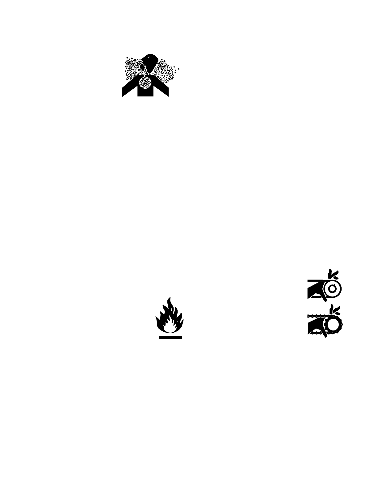
A. Avoid Carbon Monoxide Poisoning
All engine exhaust contains
carbon monoxide, a deadly gas.
Breathing carbon monoxide can
cause headaches, dizziness,
drowsiness, nausea, confusion
and eventually death.
Carbon monoxide is a colorless, odorless, tasteless gas
which may be present even if you do not see or smell
any engine exhaust. Deadly levels of carbon monoxide
can collect rapidly and you can quickly be overcome and
unable to save yourself. Also, deadly levels of carbon
monoxide can linger for hours or days in enclosed or
poorly-ventilated areas. If you experience any symptoms
of carbon monoxide poisoning, leave the area immediately,
get fresh air, and SEEK MEDICAL TREATMENT.
To prevent serious injury or death from carbon
monoxide:
• NEVER run engine indoors. Even if you try to
ventilate engine exhaust with fans or open windows
and doors, carbon monoxide can rapidly reach
dangerous levels.
• NEVER run engine in poorly-ventilated or
partially enclosed areas such as barns, garages,
basements, carports, under dwellings, or in pits.
• NEVER run engine outdoors where engine exhaust
can be drawn into a building through openings
such as windows and doors.
B. Avoid Gasoline Fires
Gasoline (fuel) vapors are highly flammable
and can explode. Fuel vapors can spread
and be ignited by a spark or flame many feet
away from engine. To prevent injury or death
from fuel fires, follow these instructions:
• NEVER store engine with fuel in fuel
tank inside a building with potential
sources of ignition such as hot water
and space heaters, clothes dryers, electric motors,
etc.
• NEVER remove fuel cap or add fuel when engine
is running.
• NEVER start or operate the engine with fuel fill cap
removed.
• Allow engine to cool before refueling.
• NEVER fill fuel tank indoors. Fill fuel tank outdoors
in a well-ventilated area.
• DO NOT smoke while refueling tank.
• Use only an approved red GASOLINE container to
store and dispense fuel. Tecumseh recommends
purchasing gasoline in containers with a capacity
of 2.5 gallons or less. Small containers are easier
to handle and help eliminate spillage during
refueling.
• DO NOT pour fuel from engine or siphon fuel by
mouth.
C. Adult Supervision of Operation, Refueling
and Maintenance
Not everyone who is allowed to use an engine is capable
of safely and responsibly operating, maintaining and/or
fueling it. Tecumseh recommends the following:
• An adult should fuel the engine. NEVER allow
children to refuel an engine.
• An adult should perform maintenance on an engine.
Only allow children to perform maintenance if an
adult has determined they are experienced and
capable of such operation.
• An adult should start the engine. Only allow children
to start the engine if an adult has determined they
are experienced and capable of such operation.
To avoid unsupervised operation of the engine, especially
by children, NEVER leave it unattended when it is
running.
D. Stay Away from Rotating Parts
NEVER operate an engine with an unguarded engine
shaft.
The equipment manufacturer may attach a sprocket and
chain or pulley and belt to the engine
shaft. If these parts are not properly
guarded, or if you are not sure whether
they are properly guarded, DO NOT
use your engine; contact the equipment
manufacturer. Hands, feet, hair, jewelry,
clothing, etc. can become entangled in
rotating parts, leading to serious injury or
death. To avoid serious injury or death,
be sure the flywheel guard is in place.
1
Page 5
General Information
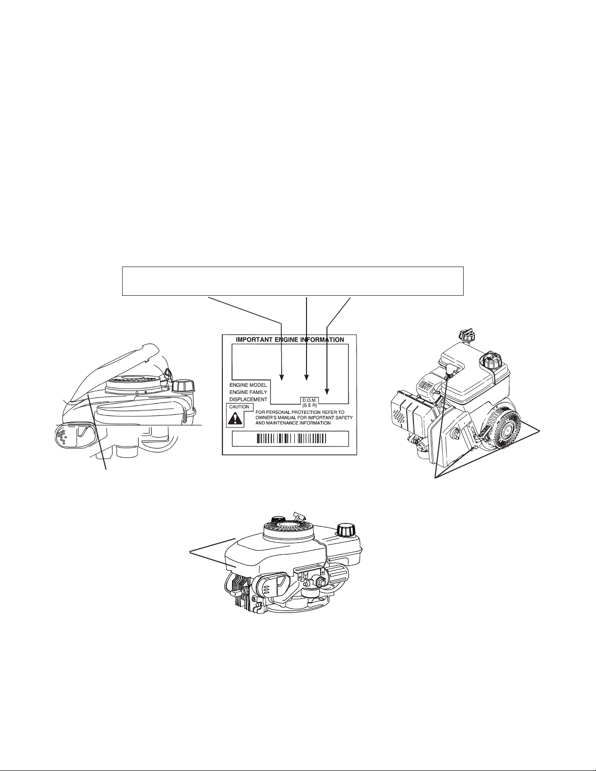
The following information is being provided to assist you in locating and recording your engine model and specification
numbers. This information will be needed to use this book or obtain parts from a local Tecumseh dealer.
Model Numbering System for Tecumseh’s Full Engine Line
Prior to 2004 Production
LOCATING AND READING ENGINE MODEL AND SPECIFICATION
THE FOLLOWING WILL BE NEEDED TO LOCATE PARTS FOR YOUR ENGINE.
Model Specification (DOM)
ENGINE: TVM195 150288G 8150C
ENGINE MODEL SPEC NO. D.O.M
TVM195 150288G 8150C
Typical Engine I.D. Label
ENGINE MODEL NUMBER
LOCATED UNDER COVER
ENGINE MODEL
NUMBER
LOCA
TIONS
TECUMSEH POWER COMPANY
THIS ENGINE MEETS 1995-1998 CALIF/US
EPA PH1 APPLICABLE EMISSION REGULATIONS FOR ULGE ENGINES FUEL REGULAR
UNLEADED OIL SAE 30
TVM195 150288G (E)
STP318U1G2EA
318 8150 C
ENGINE MODEL NUMBER LOCATIONS
2
Page 6
Model Numbering System for Current Tecumseh’s Full Engine Line
Reviewing The Engine ID Label
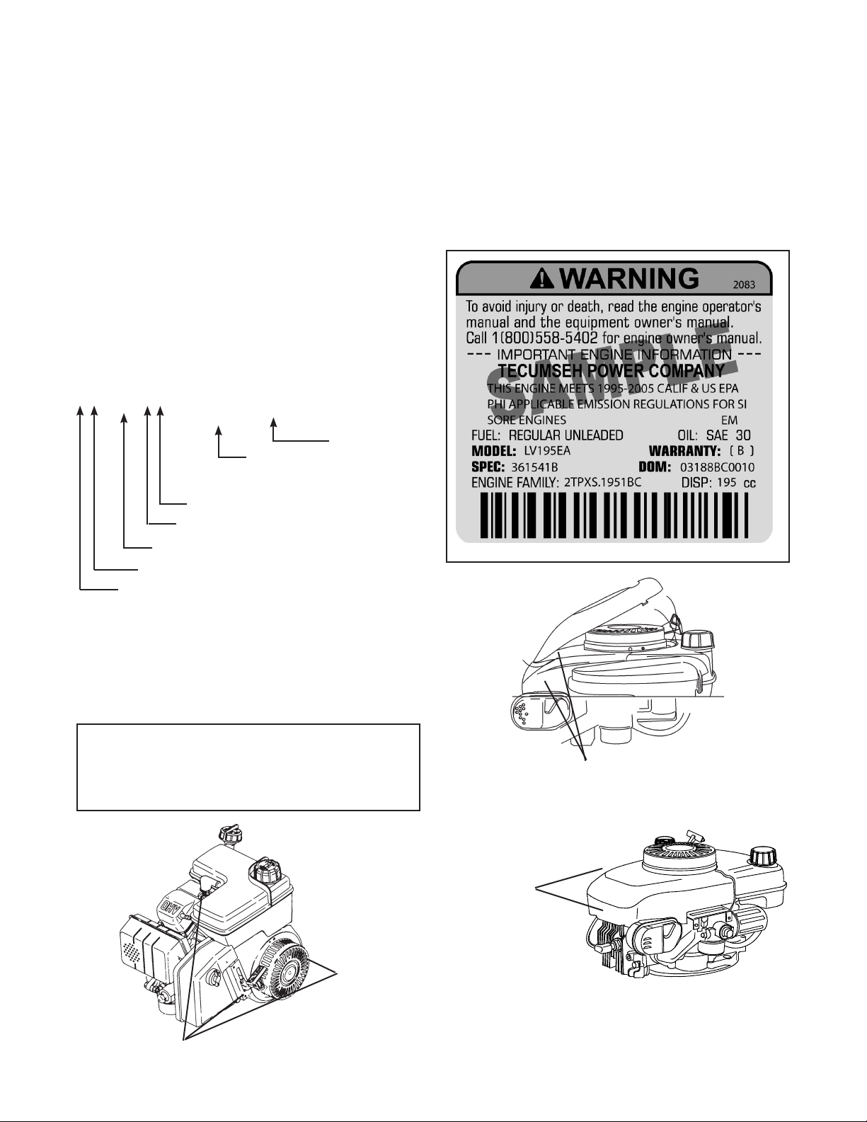
Effective with the 2004 Model Year, we have changes to the engine I.D. label on our products. The following pages
will explain the information contained on the label dependent on the age of your product.
Specification Number
The numbers following the model number make up the
specification number.
Using model LV195EA-361541B, as an example,
interpretation is as follows:
LV195EA-361541B is the model and specification
number.
L V 195 E A - 361541B (B)
{
{
Indicates a standard power configuration
Indicates EPA/CARB compliant
Indicates a 195 cc displacement
Indicates a vertical shaft configuration
Indicates an L-Head, side valve configuration
{
Warranty Code
Is the specification number used
for properly identifying the parts of
the engine
Date of Manufacture
The Date of Manufacture (D.O.M.) indicates the
production date.
For this example, 03188BC0010 is the D.O.M. (Date of
Manufacture).
Year
2005
Day of
Year
188th
Mfg
Facility
Assembly
Line / Shift
Individual
Serial #
10th unit built
05 188 B C 0010
Typical Engine
I.D. Label
Locations
ENGINE MODEL NUMBER
LOCATED UNDER COVER
ENGINE MODEL NUMBER LOCATIONS
ENGINE MODEL
NUMBER
LOCATIONS
3
Page 7
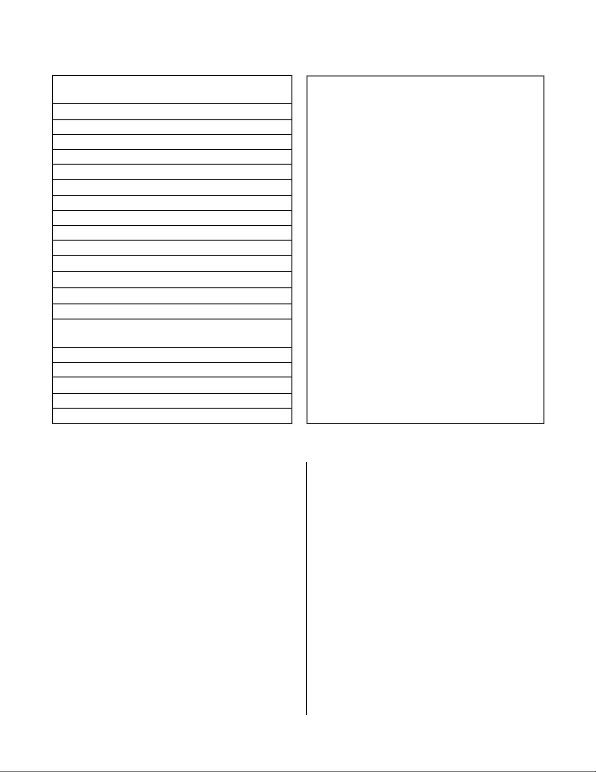
Model Numbering Identification for Tecumseh’s Full Engine Line
CURRENT CODE
(effective 2004 production)
1st Space - Valve Orientation
T = Two Cycle
O = Overhead Valve
L = L-Head
2nd Space - Crank Orientation
V = Vertical
H = Horizontal
M = Multi-position
3rd, 4th and 5th Space - Displacement
Model Number Conversion Chart
LEV90 - LV148EA OHH60 - OH195EA
LEV120 - LV195EA OHH65 - OH195EP
HSSK50 - LH195SA OHSK70 - OH195SA
HSSK55 - LH195SP OHSK75 - OH195SP
VSK90 - LV148SA HMSK90 - LH318SA
OHV135 - OV358EA HMSK110 - LH358SA
OHV180 - OV490EA OHSK110 - OH318SA
TVT691 - OV691EA OHSK130 - OH358SA
VTX691 - OV691EP OHM110 - OH318EA
Prior to 2004
4-Cycle
6th Space - Emissions Class
E = 50 State/Global Emissions Compliant
X = Not for sale in California, except exempt
applications
S = Snow Emission Compliant
7th Space - Engine Specifics
A = Standard (OHH50-60), (OHSK50-70)
P = Power Up (OHH65-70, OHSK75-775)
4-Cycle
ECH - Exclusive Craftsman Horizontal
ECV - Exclusive Craftsman Vertical
H - Horizontal Shaft
HH - Horizontal Heavy Duty (Cast Iron)
HHM - Horizontal Heavy Duty (Cast Iron)
(Medium Frame)
HM - Horizontal Medium Frame
HMSK - Horizontal Medium Frame (Snow King)
HMXL - Horizontal Medium Frame (Extra Life)
HS - Horizontal Small Frame
HSSK - Horizontal Small Frame (Snow King)
HXL - Horizontal (Extra Life)
LAV - Lightweight Aluminum Frame Vertical
LEV - Low Emissions Vertical
LH - L-Head Horizontal
LV - L-Head Vertical
OH - Overhead Valve Heavy Duty (Cast Iron)
OHH - Overhead Valve Horizontal
OH195 - Overhead Valve Horizontal (195 cc's)
OHM - Overhead Valve Heavy Duty Horizontal
(Medium Frame)
OHSK - Overhead Valve Horizontal (Snow King)
OHV - Overhead Valve Vertical (Medium Frame)
OV - Overhead Valve Vertical
OVM - Overhead Valve Vertical (Medium Frame)
2-Cycle
TC300 - TM049XA
HSK870 - TH139SP
HSK600 - TH098SA
AV520 - TV085XA
OVRM - Overhead Valve Vertical (Small Frame)
(Rotary Mower)
- Overhead Valve Vertical (Medium
OVXL
Frame) (Extra Life)
TNT - Toro ‘N’ Tecumseh (Toro Exclusive
Series)
TVEM - Tecumseh Vertical European Model
TVM - Tecumseh Vertical (Medium Frame)
(Replaces V & VM)
TVS - Tecumseh Vertical Styled
TVT - Tecumseh Vertical Twin
TVXL - Tecumseh Vertical (Extra Life)
V - Vertical Shaft
VH - Vertical Heavy Duty (Cast Iron)
VLV - Vector Lightweight Vertical
VLXL - Vector Lightweight Vertical (Extra Life)
VM - Vertical Shaft (Medium Frame)
VSK - Vertical Snow King
VTX - Vertical Twin
2-Cycle
TH - Two Cycle Horizontal Shaft
TM - Two Cycle Multiposition Operation
TV - Two Cycle Vertical Shaft
4
Page 8
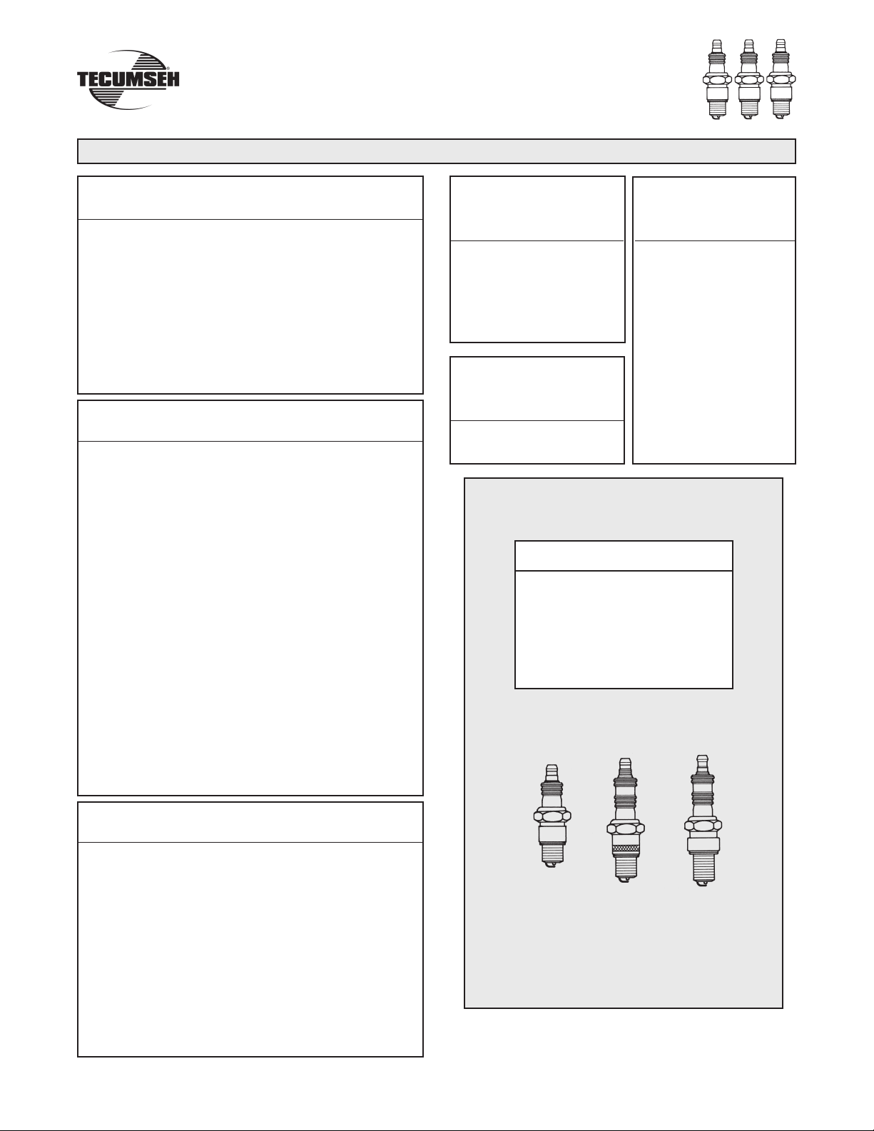
Spark Plug Replacement
NOTE: Only models which will continue to be manufactured long term will have an updated Model designation.
4-CYCLE SPARK PLUG
Service Number 35395
RJ19LM
ECV100-120
HMSK70, LH318SA (HMSK80), HMSK90
HSK30-70
HSSK40, LH195SA (HSSK50), LH195SP (HSSK55)
LH358SA (HMSK100), HMSK110
LEV80, LV148EA (LEV90), LV195EA (LEV120)
LV148SA (VSK90), VSK100
TNT100
TNT120
TVS75-120
TVXL90-120
Service Number 34645
RN4C
OH318EA (OHM90-110)
†
OHM120
OH195EA (OHH60), OH195EP (OHH65)
OHH/OHSK40-130
OH195SA (OHSK70), OH195SP (OHSK75)
‡
OH318SA (OHSK110), OH358SA (OHSK120-130)
OH180
OV195EA
OV358EA (OHV110-135), OV490EA (OHV140-180)
OV691EP (VTX691, TVT691)
OVM120
* OVXL120
* OVXL/C120
* OVXL125
OV195
Note:
* OVXL models with specification nos. below 202700 use
RL86C.
†
OHM120 models with specification nos. below 224000 use
RL86C.
‡
OHSK110 - 130 models with specification nos. below
223000 use RL86C.
Service Number
33636
RJ17LM
H30-80
HM70-100
HS40-50
TVM195-220
TVXL195-220
VLV-all
Service Number
35552
RL82C
HH140-160
OH120-160
NOTE: THE SERVICE NUMBERS LISTED BELOW
WILL
GIVE CORRESPONDING CHAMPION
AND AUTOLITE SUBSTITUTIONS.
Service Number
34277
RJ8C
H22
H25
HH40-120
HHM80
HMXL70
HT30
HT35
HXL35
LAV25-50
TVM125-170
V40-80
VH40-100
VM70-100
Champion Autolite
35395 - RJ19LM NA
35552 - RL82C 4092
34046 - RL86C 425
34645 - RN4C 403
33636 - RJ17LM 245
34277 - RJ8C 304
SPARK PLUG AIR GAP ON ALL MODELS IS
.030 (.762 mm)
Service Number 34046
RL86C
†
OHM120
‡
OH318SA (OHSK110), OH358SA (OHSK120-130)
OVM120
* OVXL120
* OVXL/C120
* OVXL125
Note:
* OVXL models with specification nos. 202700, 203000 and
up, use RN4C.
†
OHM120 models with specification nos. 224000 and up,
use RN4C.
‡
OHSK110, OHSK120-130 models with specification nos.
223000 and up, use RN4C.
Note: If you need assistance locating your engine model numbers please check page 3 or 4.
3/8"
9.525 mm
NOTE:
Not all spark plugs have the same heat range or reach.
Using an incorrect spark plug can cause severe engine
damage or poor performance. Tecumseh uses all three
of the reaches shown.
1/2"
12.700 mm
19.050 mm
FOR TWO CYCLE INFORMATION
REFER TO NEXT PAGE.
5
3/4"
Page 9
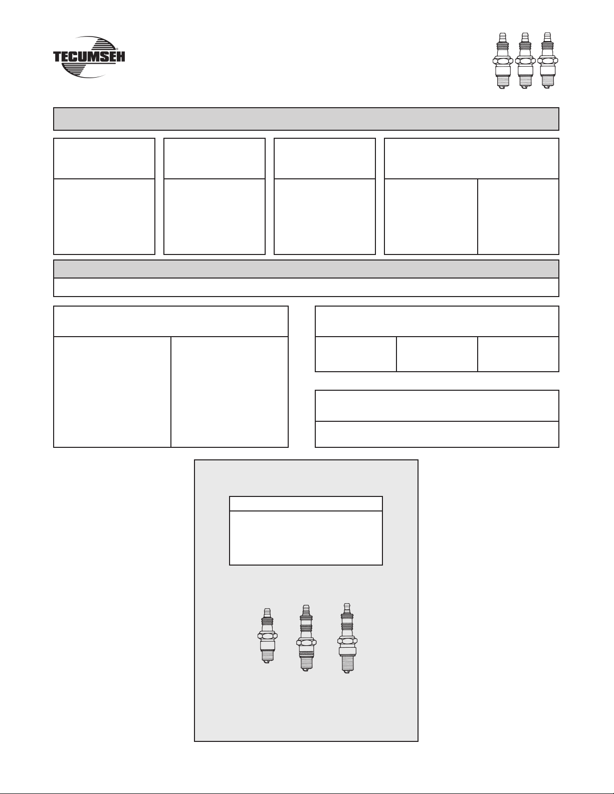
Spark Plug Replacement
NOTE: Only models which will continue to be manufactured long term will have an updated Model designation.
2-CYCLE SPARK PLUG
Service Number
611100
Service Number
33636
Service Number
35395
Service Number 61
RCJ6Y RJ17LM RJ19LM RCJ8Y
TC300
TCH300
TM049XA
A
V600
AV520
TVS600
TV085XA
TVS840
TVXL840
AH520
AH600
HSK840
HXL840
TC200
TCH200
TH098SA
EUROPA MODELS
4-CYCLE SPARK PLUG
Service Number 33636 Service Number 34645
RJ17LM RN4C
All Horizontal Models
BV
BVL
BVS
Centura
Futura
HTL
LAV
Legend
Premier 153/173
Prisma
Spectra
Synergy
Vantage
Centrua OHV
Futura OHV
2-CYCLE SPARK PLUG
RJ17LM
AV85/125
AV520/600
Geotec OHV
Premier 45/55
Service Number 33636
MV100S
TVS600
Type 1500
1049
HSK600
HSK635
TH139SA
HSK845, 850
TH139SP
HSK870
Synergy OHV
NOTE: THE SERVICE NUMBERS LISTED BELOW
WILL
GIVE CORRESPONDING CHAMPION
AND AUTOLITE SUBSTITUTIONS.
Champion Autolite
35395 - RJ19LM NA
33636 - RJ17LM 245
611100 - RCJ-6Y 2974
611049 - RCJ-8Y 2976
SPARK PLUG AIR GAP ON ALL MODELS IS
.030 (.762 mm)
3/8"
9.525 mm
NOTE:
Not all spark plugs have the same heat range or reach. Using an
incorrect spark plug can cause severe engine damage or poor
performance. Tecumseh uses all three of the reaches shown.
Note: If you need assistance locating your engine model numbers please check page 3 or 4.
1/2"
12.700 mm
6
3/4"
19.050 mm
Page 10

Fuel Recommendations
WARNING
Today’s fuels have a short shelf life and it is recommended you buy no more than a two week
supply at a time.
GASOLINE
Tecumseh Power Company strongly recommends the use of fresh, clean, unleaded regular gasoline in
all Tecumseh engines. Unleaded gasoline burns cleaner, extends engine life, and promotes good starting
by reducing the build-up of combustion chamber deposits. Leaded gasoline, gasohol containing no more
than 10% ethanol, premium gasoline, or unleaded gasoline containing no more than 15% MTBE (Methyl
Tertiary Butyl Ether), 15% ETBE (Ethyl Tertiary Butyl Ether) or 10% ethanol, can be used if unleaded
regular gasoline is not available.
Reformulated gasoline that is now required in several areas of the United States is also acceptable.
NEVER USE gasoline, fuel conditioners, additives or stabilizers containing methanol, gasohol containing
more than 10% ethanol, unleaded regular gasoline containing more than 15% MTBE (Methyl Tertiary Butyl
Ether), 15% ETBE (Ethyl Tertiary Butyl Ether) or 10% ethanol, gasoline additives, or white gas because
engine/fuel system damage could result.
SPECIALTY FUELS
Fuels being marketed for use on small engines can have a significant effect on starting and engine
performance. Prior to using any specialty fuel, the Reid Vapor Pressure (RVP) must be determined. Fuels
with a rating of less than 50kPa (7psi) should not be used in summer, and fuel with a rating of 85kPa
(12psi) should not be used during winter.
SHORT TERM STORAGE
NEVER store the engine with fuel in the fuel tank inside a building with potential sources
of ignition such as hot water and space heaters, clothes dryers, electric motors, etc.
engine fuel stored in the gas tank and/or an approved gas container is to be unused without gasoline
If
stabilizer for more than 15-30 days, prepare it for short term/seasonal storage.
ecumseh recommends using UL
T
Cleaner as an acceptable method of minimizing formation of fuel gum deposits during storage. This product
is available from your Authorized Tecumseh Servicing Dealer.
Always follow mix ratio found on stabilizer container. Failure to do so may result in equipment damage.
It is not necessary to drain stabilized gas from carburetor.
TREATMENT
FUEL
1. Add fuel stabilizer according to manufacturer’s instructions.
2. Run engine at least 10 minutes after adding stabilizer to allow it to reach carburetor.
TRA-FRESH™ or Fuel Saver Plus Gasoline Stabilizer plus Fuel System
3. Instead of using a fuel preservative/stabilizer, you can empty the fuel tank as described under "Extended
Storage”.
7
Page 11

Fuel Recommendations - continued
EXTENDED STORAGE
NOTES
Clean debris from engine before draining fuel from carburetor
term storage it is not necessary to drain fuel that contains stabilizer from your carburetor.
To avoid severe injury or death, DO NOT pour fuel from engine or siphon fuel by mouth.
1. To prevent serious injury from fuel fires, empty fuel tank by running engine until it stops from lack of
fuel. DO NOT attempt to pour fuel from engine.
2. Run the engine while waiting until the remaining fuel is consumed.
NEVER leave the engine unattended when it is running and NEVER run engine in enclosed areas.
FUEL
ADDITIVES
Only fuel additives such as Tecumseh’s fuel stabilizer Part No. 730245A or liquid varieties can be used
when mixed properly. For winter applications, Isopropyl alcohol fuel dryers may be used in the fuel system
but must be mixed at the proper ratio recommended by the manufacturer. NEVER USE METHANOL
BASED FUEL DRYERS.
. If you have prepared your fuel for short
8
Page 12
TECUMSEH 4-CYCLE LUBRICATION REQUIREMENTS
Tecumseh recommends the use of a high quality, brand
name oil with a minimum classification of SL/SJ. Very
few air cooled engines have any type of oil filtration
system, making regular oil changes critical to remove
TECUMSEH
4-CYCLE ENGINE OIL
shown with model names prior to 2004
CLASSIFICATIONS: “SL/SJ"
DO NOT USE 10W40
CAPACITIES:
Engine Model ml
All LAV, TVS, LEV, OVRM ................................ 630 21
ECV, TNT .......................................................... 630 21
V & VH50-70 ..................................................... 810 27
TVM 125, 140 ................................................... 810 27
TVM 170-220 .................................................... 960 32
VM70-100, HHM80 ........................................... 960 32
VH100 ............................................................... 1500 50
All VLV .............................................................. 810 27
VSK90-100 ......................................................... 630 21
OVM120, OVXL120, 125 .................................. 960 32
OHV11-13 Without Filter ................................... 960 32
OHV11-13 With Filter .........................................1170 39
OHV13.5-17 With Filter ..................................... 1800 61
OHV13.5-17 Without Filter ................................ 1650 55
TVT691 With Filter ............................................ 2150 71
TVT691 Without Filter ....................................... 1950 64
H, HSK30-35 ..................................................... 630 21
HS, HSSK40-50 ................................................ 630 21
H, HH, HSK50-70 ............................................. 570 19
OHH/OHSK50-70 ............................................. 630 21
HMSK, HM70-100 ............................................. 720 26
OHSK80-100 .................................................... 720 26
OHM120, OHSK110*-130 ................................. 840 28
HH100,120, OH120-180 ................................... 1560 52
*NOTE: Model OHSK110 with a spec. of 221000 and up, have a
capacity of 26 oz. (720 ml).
Oz.
impurities from the engine and maximize engine life.
Consult the operator's or repair manual for the oil
change interval and viscosity based on equipment
operating temperature.
TECUMSEH
4-CYCLE ENGINE OIL
shown with model names
2004 production and later
Engine Model ml Oz.
LH195SA, LH195SP 630 21
LH318SA, LH358SA 720 26
LV148EA, LV148SA 630 21
LV195EA 630 21
OH195EA, OH195EP 630 21
OH195SA, OH195SP 630 21
OH318EA 720 26
OH358SA 840 28
OV195EA 630 21
OV358EA With Filter 1170 39
OV358EA Without Filter 960 32
OV490EA With Filter 1800 61
OV490EA Without Filter 1650 55
OV691EA With Filter 2150 71
OV691EA Without Filter 1950 64
OV691EP With Filter 2150 71
OV691EP Without Filter 1950 64
EUROPA MODELS *
VERTICALS
ml Oz.
Vantage 630 21
Prisma 630 21
Synergy 630 21
Synergy "55" 810 27
Spectra 630 21
Futura 630 21
HTL 630 21
BVS 630 21
HORIZONTALS
BH Series 630 21
Geotec Series 35-50 630 21
NOTE: Vertical shaft engines with auxiliary PTO:
26 oz. (700 ml).
9
Page 13
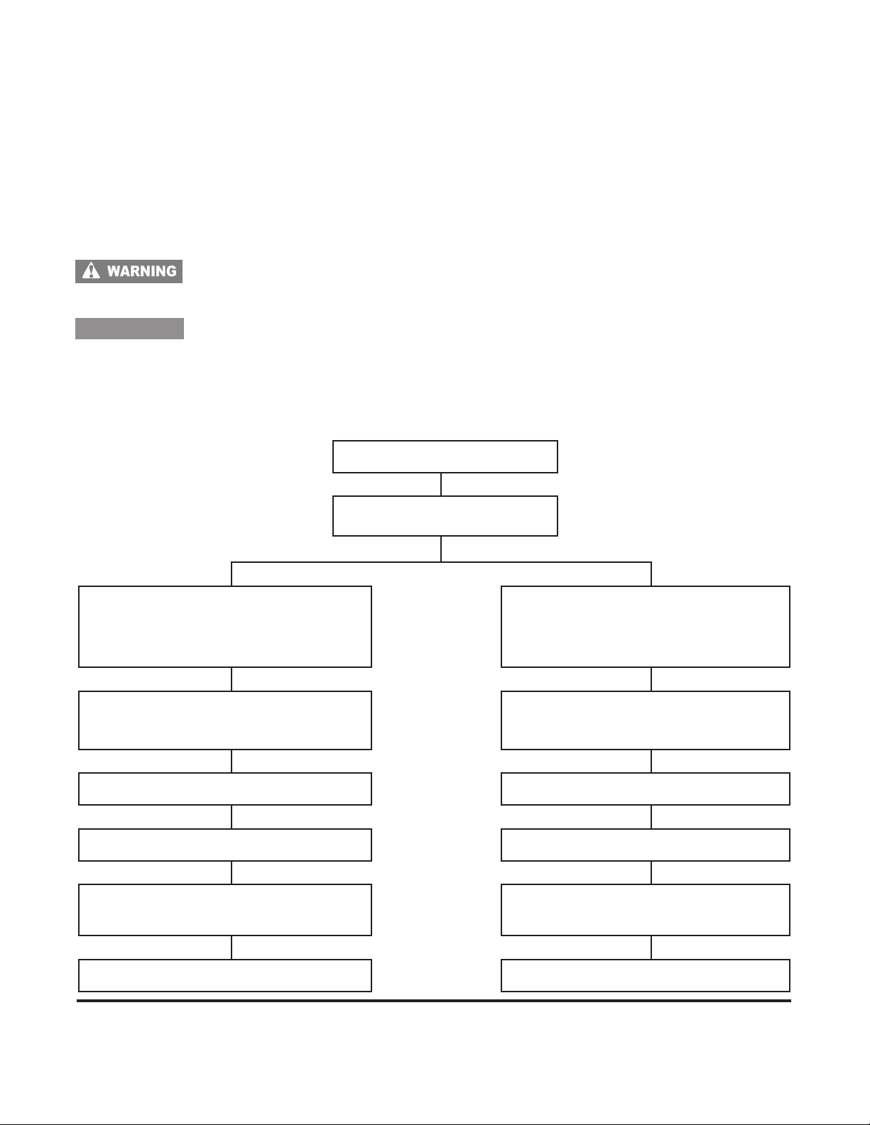
Four Cycle Troubleshooting
The following is provided as a basic troubleshooting guide. Its use requires a complete review of all conditions
and symptoms. Always examine the exterior for clues: leaks, excessive dirt, or obvious damage. Some repairs will
require the assistance of a Tecumseh Servicing Dealer.
Preparation
Before troubleshooting any system problem, see original equipment manufacturer’s (O.E.M.) instructions.
Make your troubleshooting easier by preparing as follows:
• Work in a clean, well-lighted place.
• Keep proper tools and materials nearby.
• Keep an adequate supply of clean petroleum-based solvent.
To reduce the risk of serious injury or death from fires and/or explosions, NEVER use flammable
solvents (e.g., gasoline) to clean serviceable parts. Use a water-based, non-flammable solvent
such as Tecumseh Degreaser Cleaner.
CAUTION
• Wear appropriate eye protection.
• Use only approved air blow nozzles.
NEVER use compressed air to clean debris from yourself or your clothing. When using compressed
air to clean or dry serviceable parts:
• Air pressure must not exceed 30psi (206kPa).
• Shield yourself and bystanders from flying debris.
FUEL SYSTEM
Engine Will Not Start
et Dry
W
Defective spark plug
Use Tester 670366
Restricted air filter
Improper or stale fuel Check fuel supply and fuel cap vent
Exhaust ports plugged Restriction in fuel system (filter)
Carburetion problems due to fl
over priming, etc.*
Check if spark plug is wet or
dry
ooding,
Review with the customer proper
priming procedure (3-5 primes,
waiting 2 seconds between each
prime)
If equipped with a choke, check for full
travel. Check throttle cable and control
for proper adjustment.
Carburetion problem*
(bad bowl gasket)
Ignition System Poor Compression
Should more extensive repair be needed, we recommend you contact a local Tecumseh Servicing Dealer for repair.
Repair manuals are also available from your local dealer or direct from Tecumseh. A complete list of the available
manuals can be found at the end of this book.
NOTE: Refer to Technician's Handbook for a more detailed list of remedies.
10
Page 14
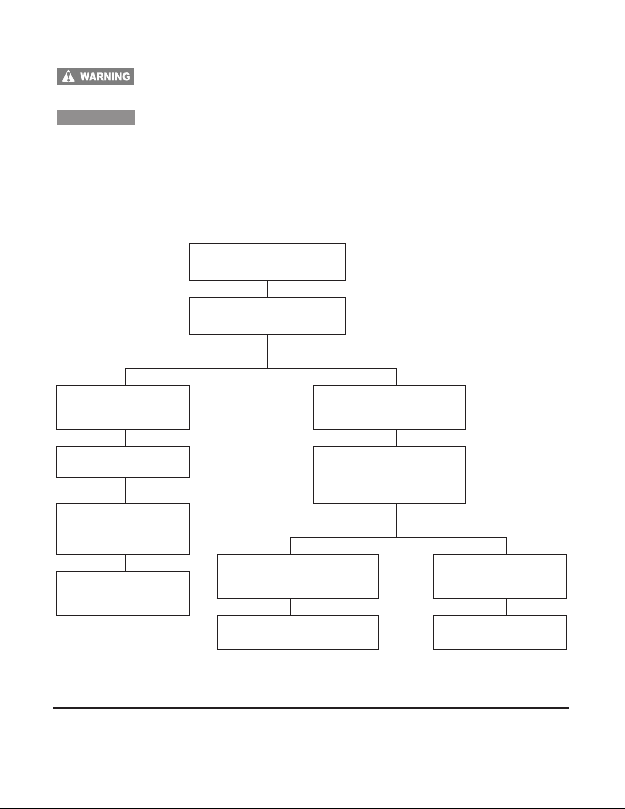
Four Cycle Troubleshooting - continued
To reduce the risk of serious injury or death from fires and/or explosions, NEVER use flammable
solvents (e.g., gasoline) to clean serviceable parts. Use a water-based, non-flammable solvent
such as Tecumseh Degreaser Cleaner.
CAUTION
• Wear appropriate eye protection.
• Use only approved air blow nozzles.
NEVER use compressed air to clean debris from yourself or your clothing. When using compressed
air to clean or dry serviceable parts:
• Air pressure must not exceed 30psi (206kPa).
• Shield yourself and bystanders from flying debris.
IGNITION SYSTEM
Engine Will
Not Start
Check for Spark
Spark No Spark
Check flywheel for
correct key, damaged
or sheared key
Set proper air gap on
external coil
Set proper point gap,
check condensor and
timing
T
est coil for
intermittent or weak
spark
Replace spark plug
Isolate engine from all
equipment (disconnect
wiring harness), repeat
test
Spark No Spark
Equipment problem,
check switches, wiring and
equipment controls
Parasitic load too high T
Engine problem, check
for shorts or grounds
in wiring
est ignition module
Should more extensive repair be needed, we recommend you contact a local Tecumseh Servicing Dealer for repair.
Repair
manuals can be found at the end of this book.
NOTE: Refer to Technician's Handbook for a more detailed list of remedies.
manuals are also available from your local dealer or direct from Tecumseh. A complete list of the available
11
Page 15
TECUMSEH 2-CYCLE ENGINE OIL REQUIREMENTS
The proper type and ratio of 2-cycle oil is critical to
long life and low maintenance of the engine. The use
of non-certified oils and improper mix ratio’s can cause
severe engine damage and possibly void warranty
consideration.
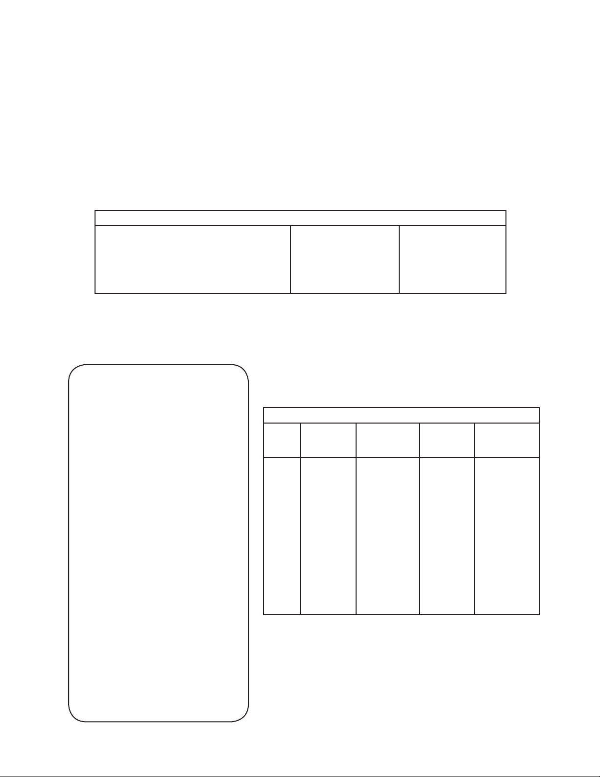
TWO-CYCLE FUEL/OIL MIX RATIOS
24:1 32:1 50:1
AV520 Types 670 & 653, TV085
TV085XA (AV600 Type 600-10 & Up)
TC200, TCH200, TCH300
TM049XA (TC300)
MV100S
Sears/Craftsman 40:1 2-Cycle Oil has been tested and approved for use in all engines,
EXCEPT the TC / TM Models which require a 24:1 Ratio.
The following is a list of 2-cycle engine oil classifications
which are certified for use in Tecumseh
2-cycle engines:
• National Marine Manufactures Association,
(NMMA), TC-WII or TC-W3
• American Petroleum Institute, (API), TC
• Japanese Automobile Standard Organization,
(JASO), FB or FC
TVS600 ALL TYPES
AH600
TVS /
TVXL
HSK840 - 870 - TH139
HSK600 - 635 - TH098
2-CYCLE
SYNTHETIC BLEND
ENGINE OIL WITH
FUEL STABILIZER
PART NO. 730227D
TECUMSEH 2-CYCLE ENGINE
OIL may be used in a variety of
2-cycle engines including: outboards,
lawnmowers, snow-blower, string
trimmers, and edgers at any fuel/oil
mixing ratio up to 50:1.
• Superior Lubricity Extends engine
life by reducing wear
• Longer Spark Plug life through
reduced fouling
• Reduces Carbon Build-Up
extending required service intervals
• Helps maintain emissions
compliance which helps our
environment
• Contains Fuel Stabilizer-Extends
fuel life and protects fuel system
ENGINE FUEL MIX
U.S.
Gasoline
24:1 1 Gallon 5 oz. 4 Liters 167 ml
2 Gallons 1
5 Gallons 27 oz. 20 Liters 833 ml
32:1 1 Gallon 4 oz. 4 Liters 125 ml
2 Gallons 8 oz. 8 Liters 250 ml
5 Gallons 20 oz. 20 Liters 625 ml
50:1 1 Gallon 2.5 oz. 4 Liters 80 ml
2 Gallons 5 oz. 8 Liters 160 ml
5 Gallons 13 oz. 20 Liters 400 ml
U.S.
Amount of Oil
T
o Be Added
1 oz. 8 Liters 333 ml
METRIC
Petrol
METRIC
Amount of Oil
To Be Added
12
Page 16
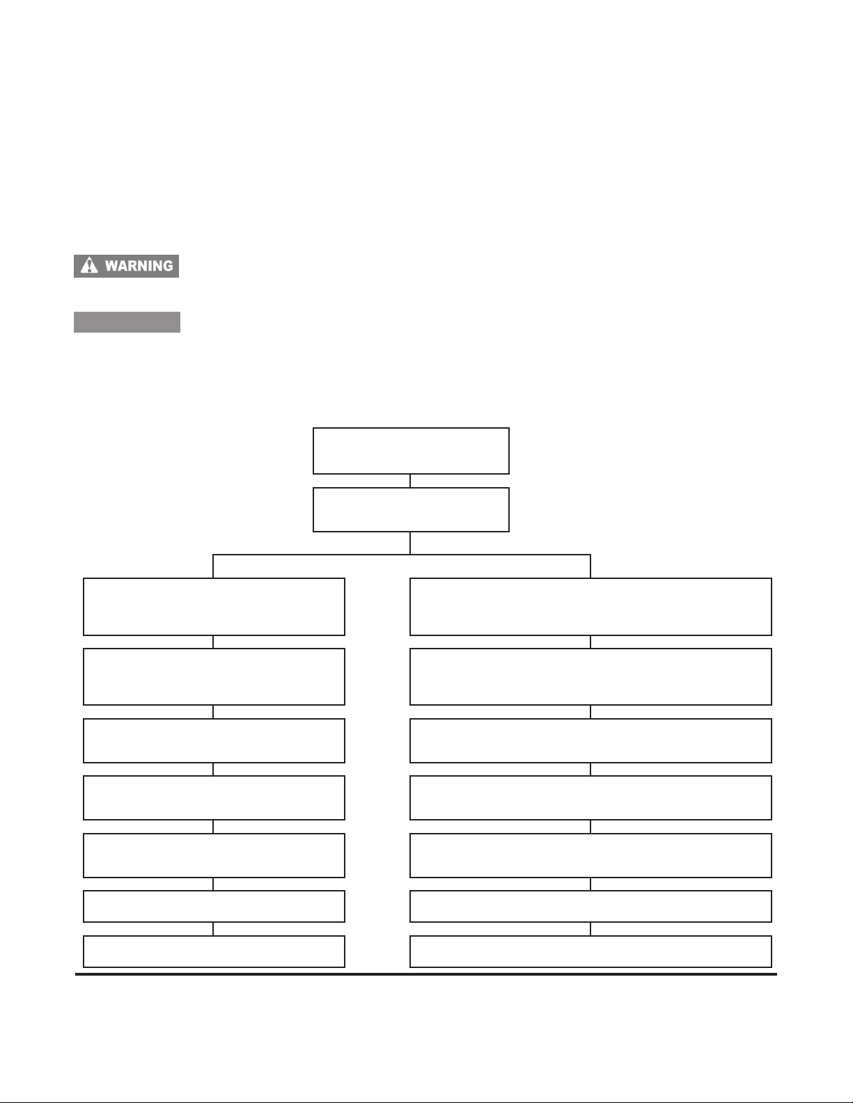
Two Cycle Troubleshooting
The following is provided as a basic troubleshooting guide. Its use requires a complete review of all conditions
and symptoms. Always examine the exterior for clues: leaks, excessive dirt, or obvious damage. Some repairs will
require the assistance of a Tecumseh Servicing Dealer.
Preparation
Before troubleshooting any system problem, see original equipment manufacturer’s (O.E.M.) instructions.
Make your troubleshooting easier by preparing as follows:
• Work in a clean, well-lighted place.
• Keep proper tools and materials nearby.
• Keep an adequate supply of clean petroleum-based solvent.
To reduce the risk of serious injury or death from fires and/or explosions, NEVER use flammable
solvents (e.g., gasoline) to clean serviceable parts. Use a water-based, non-flammable solvent
such as Tecumseh Degreaser Cleaner.
CAUTION
• Wear appropriate eye protection.
• Use only approved air blow nozzles.
NEVER use compressed air to clean debris from yourself or your clothing. When using compressed
air to clean or dry serviceable parts:
• Air pressure must not exceed 30psi (206kPa).
• Shield yourself and bystanders from flying debris.
FUEL SYSTEM
Engine Will Not
Start
Wet Dry
Defective spark plug
Restricted air filter
Improper fuel mix or stale fuel
Sheared or partially sheared
flywheel key
Carburetion problems due to
flooding, over priming, etc.*
Check if spark plug is
wet or dry
Review with customer priming or choking
procedure (3-5 primes, if equipped, waiting 2
If equipped with a choke, check for full travel.
Check throttle cable and control for proper
Check fuel supply and fuel cap vent
seconds between each prime)
adjustment.
Carburetion problem*
(bad bowl gasket)
Restriction in fuel system
, screen)
(filter
Ignition System Poor compression
Crankcase seals or gaskets leaking Damaged reed, port plugs, seals or gaskets
Should more extensive repair be needed, we recommend you contact a local Tecumseh Servicing Dealer for repair.
Repair manuals are also available from your local dealer or direct from Tecumseh. A complete list of the available
manuals can be found at the end of this book.
NOTE: Refer to Technician's Handbook for a more detailed list of remedies.
13
Page 17
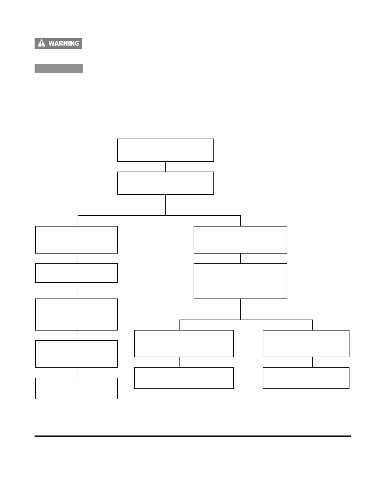
Two Cycle Troubleshooting - continued
To reduce the risk of serious injury or death from fires and/or explosions, NEVER use flammable
solvents (e.g., gasoline) to clean serviceable parts. Use a water-based, non-flammable solvent
such as Tecumseh Degreaser Cleaner.
CAUTION
• Wear appropriate eye protection.
• Use only approved air blow nozzles.
NEVER use compressed air to clean debris from yourself or your clothing. When using compressed
air to clean or dry serviceable parts:
• Air pressure must not exceed 30psi (206kPa).
• Shield yourself and bystanders from flying debris.
IGNITION SYSTEM
Engine Will
Not Start
Check for Spark
Spark No Spark
Check flywheel for
correct key, damaged
key or key adaptor
Set proper air gap on
external coil
Set proper point gap,
check condensor and
timing (if equipped)
T
est coil for
intermittent or weak
spark
Check electric starter
if applicable
Replace spark plug
Isolate engine from all
equipment (disconnect
wiring harness), repeat
test
Spark No Spark
Equipment problem,
check switches, wiring and
equipment controls
Parasitic load too high T
Engine problem, check
for shorts or grounds in
wiring
est ignition module
Should more extensive repair be needed, we recommend you contact a local Tecumseh Servicing Dealer for repair.
Repair
manuals can be found at the end of this book.
NOTE: Refer to Technician's Handbook for a more detailed list of remedies.
manuals are also available from your local dealer or direct from Tecumseh. A complete list of the available
14
Page 18

Cross Reference for Specification - To - Model Number Designation
This cross reference chart allows you to determine an engine Model Number if you only have the Specification
Number.
VERTICAL 4-CYCLE ENGINES
Specification Model
Number Series Number
10000 TNT100
12000 TNT120
20000 LAV25, OVRM55
20500 OVRM105
21000 OVRM60
21800 OVRM60
22000 OVRM65, OVRM120
23000 OV195EA (RM)
23500 OV195EA (Utility)
30000 LAV30
33000 TVS75
40000 LAV35
42000 OVRM905 (Sears Only)
42600 OVRM40, OVRM45 (Premier Engine)
42900 OVRM40 (High Tech Look)
43000 TVS90
43600 TVS90 (Premier Engine)
43700 TVS90, TVXL90
43900 TVS90 (High Tech Look)
44000 TVS100
44600 TVS100 (Premier Engine)
44800 TVS100
46000 TVS90, TVXL90
46600 TVS90
48000 TVS90
50000 V40
50200 LAV40
52600 OVRM50, OVRM55 (Premier Engine)
52800 OVRM50, OVRM55
52900 OVRM50, OVRM55 (High Tech Look)
53000 TVS105
53600 TVS105 (Premier Engine)
53800 TVS105
53900 TVS105 (High Tech Look)
54000 TVXL105
56000 TVS105, TVS & TVXL115
56600 TVS105, TVS115 (Premier Engine)
56800 TVS115
56900 TVS105, TVS115 (High Tech Look)
57000 TVS & TVXL115
57600 TVS115 (Premier Engine)
57800 TVS115
57900 TVS115 (High Tech Look)
60000 V50, TVM125
61000 TVS & TVXL115
61600 TVS & TVXL115
61800 TVS115
61900 TVS115
62000 LAV50
62100 LAV50 & TVS115
63000 TVS120
63200 TVS120, TVEM120
63600 TVS120 (Premier Engine)
63900 TVS120 (High Tech Look)
66000 TVS120
66100 TVS120
70000 V60, TVM140
80000 VH40
90000 VH50
100000 VH60
125000 V70
127000 VM70, TVM170
127200 TVXL170
135000 VH70
Specification Model
Number Series Number
145000 ECV100
147000 ECV105
148000 VH80
149000 VH100
150000 V & VM80, TVM195
150200 TVM & TVXL195
150500 TVM195
151000 ECV110, TVM195
151500 TVM220
152000 ECV120
157000 VM100, TVM220
157200 TVM & TVXL220
157400 TVM220
200000 OVM120
202000 OVXL120, OVXL125
202200 OVXL120 (I/C)
202300 OHV11, OHV115
202400 OVXL125
202500 OHV115
202600 OVXL125 (I/C)
202700 OHV12, OVXL120 (Tec.1200)
203000 OHV125, OVXL125 (Tec1250)
203200 OHV13
203500 OVXL125 (Tec.1250I/C), OHV13/135
203600 OHV14/140
203800 OHV145
204000 OHV15/150
204200 OHV16/160
204400 OHV165
204500 OHV155
204600 OHV17/170
204800 OHV175
206000 OHV110
206200 OHV115
206400 OHV120
206600 OHV125
206800 OHV130
206900 OHV135,OV358EA (Sm. Enduro)
208000 OHV180,OV490EA (Lg. Enduro)
334000 LEV90, LV148EA
334500 VSK90, LV148SA
335000 LEV100
338000 LEV100
338500 VSK100
340000 LEV100
345000 LEV100
346000 LEV105
347000 LEV105
348500 VSK105
350000 LEV115
355000 LEV115
360000 LEV115
361000 LEV120
361400 VSK120
361500 LEV120, LV195EA (Utility)
362000 LEV120, LV195EA (RM)
400000 VLV40
500000 ULT, VLV B24, VLXL50, & VLV126
501000 ULT, VLV, VLXL55, & VLV126
502000 ULT, VLV60, VLV65, & VLV126
502500 VLV65, VLV66
600400 TVT691
600800 TVT691, OV691EA (Twin)
600900 VTX691, OV691EP (Twin)
15
Page 19

Cross Reference for Specification - To - Model Number Designation
This cross reference chart allows you to determine an engine Model Number if you only have the Specification
Number.
HORIZONTAL 4-CYCLE ENGINES
Specification Model
Number Series Number
15000 H22
25000 H25
26000 OHH45
35000 H30
35400 HSK30
35800 H30
36700 H30
45000 H & HT35
45400 HSK35
45800 H35
46700 H35
47000 HXL35
55000 H40
55200 HS & HSSK40
55500 HSK40
55700 H40
55800 H40
55900 HSSK40
65000 H50
65300 HSK50
67000 HS & HSSK50, LH195SA
67500 HSSK55, LH195SP
68000 OHH50
68500 OHSK50
69000 OHH55
69500 OHSK55
71100 OHH60, OH195EA
71500 OHSK60
71700 OHH65
71800 OHH65, OH195EP
71900 OHSK65
72000 OHH70
72500 OHSK70, OH195SA (Premium)
73500 OHSK75, OH195SP (Premium)
75000 H60
76000 HSK60
85000 HH40
95000 HH50
105000 HH60
110000 HH80
115000 HH100
Specification Model
Number Series Number
120000 HH120
130000 H70
130200 HSK70
132000 HM & HMSK70
132500 HMXL70
140000 HH70
146000 ECH90
155000 H & HM80
155000 HMSK80
155800 HM85
155900 HM & HMSK85
156000 HM90
156500 HMSK90, LH318SA
159000 HM & HMSK100, LH358SA
159900 HMSK105
159950 HMSK110
160000 HH & OH140
170000 HH150 & 160
170000 OH160
175000 OH120
180000 OH180
190000 HHM80
220000 OHM120
221000 OHSK110
221200 OHSK80
221400 OHSK90
221600 OHSK100
221700 OHSK110
221800 OHSK115, OH318SA (Premium)
222000 OHSK120
222300 OHM90
222500 OHM100
222700 OHM110, OH318EA
223000 OHSK90
223400 OHSK110
223600 OHSK120
223700 OHSK125
223800 OHSK130, OH358SA (Premium)
VERTICAL 2-CYCLE ENGINES
Specification Model
Number Series Number
3600 TC300, TM049XA
670000 AV520, TV085XA
HORIZONTAL 2-CYCLE ENGINES
Specification Model
Number Series Number
1720 HSK635, TH098SA
8300 HSK850, TH139SA
8700 HSK870, TH139SP
16
Page 20
TECUMSEH AND PEERLESS
®
MODEL AND SPECIFICATION NUMBERS
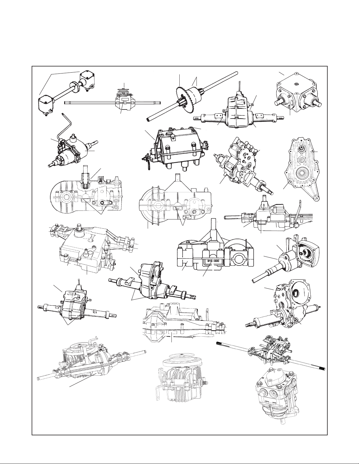
The following information is being provided to assist you in locating and recording your Tecumseh transmission
components model and specification numbers. This information will be needed to use this book or obtain parts from
a local Tecumseh dealer.
RIGHT ANGLE DRIVES
300 SERIES
100 SERIES
A or B
1100 SERIES
1200 SERIES
600 SERIES
2300 SERIES
A
700 SERIES
A or B
810 SERIES
801 SERIES
A
900 SERIES
920 SERIES
930 SERIES
A
820 SERIES
2400 SERIES
A
915 SERIES
A
A
A or B
2600 SERIES
A or B
A
910 SERIES
A
1300 SERIES
A
2500 SERIES
A
A
2800 SERIES
A or B
A or B
LTH SERIES
THE MODEL NUMBER WILL BE FOUND ON:
A. Metal tag or decal attached to unit in the location shown.
B. Stamped on unit in the location shown.
A
MST
850 SERIES
2100 SERIES
LDP-10
17
Page 21
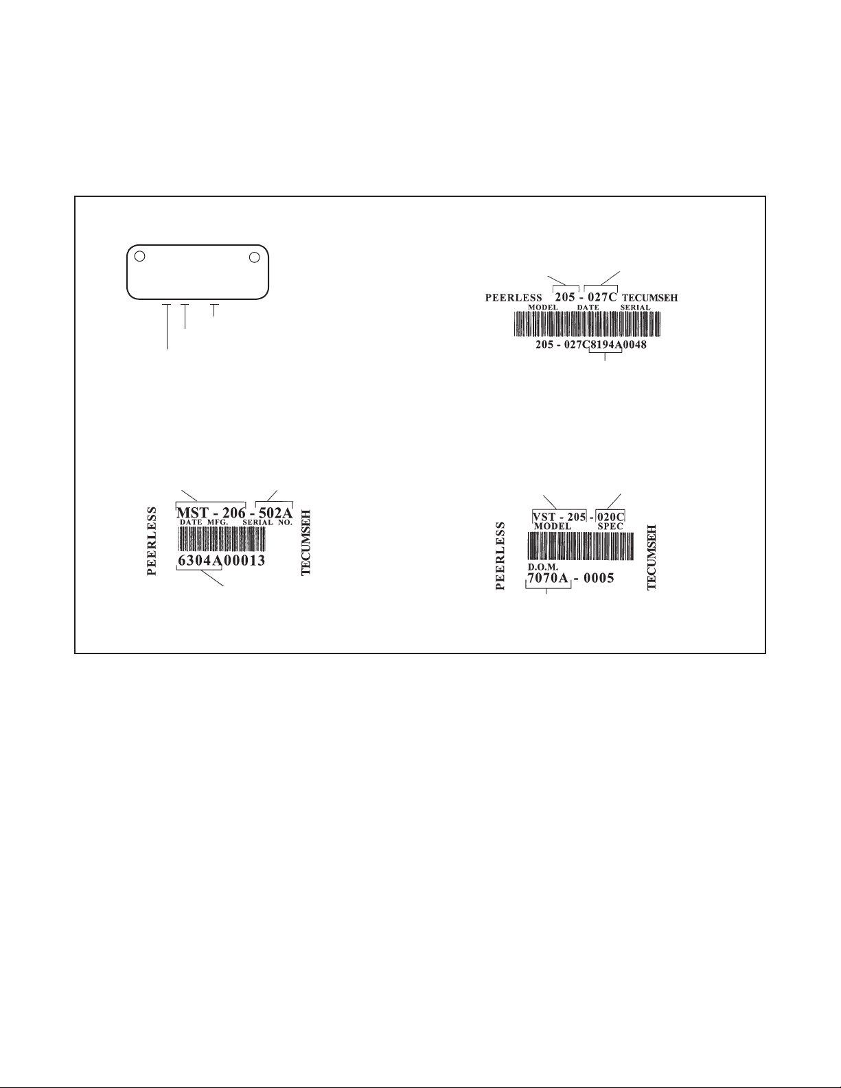
Various Styles of Identification Used On
Tecumseh and Peerless Transmission, Transaxle and
Gear Products
MOD 506
PEERLESS
1 275 1374
Individual Serial Number
Manufactured on the 275th Day
Manufactured in 1991
MODEL NUMBER REQUIRED
FOR WARRANTY
D.O.M. (DATE OF MANUFACTURE)
ORIGINAL SERIAL NUMBER
SPECIFICATION NUMBER
REQUIRED FOR WARRANTY
MODEL NUMBER REQUIRED
FOR WARRANTY
D.O.M. (DATE OF MANUFACTURE)
ORIGINAL SERIAL NUMBER
MODEL NUMBER REQUIRED
FOR WARRANTY
D.O.M. (DATE OF MANUFACTURE)
ORIGINAL SERIAL NUMBER
SPECIFICATION NUMBER
REQUIRED FOR WARRANTY
SPECIFICATION NUMBER
REQUIRED FOR WARRANTY
Early Models were not identified with a model number on the unit.
18
Page 22
Basic Gear Drive Troubleshooting
WARNING
WARNING
WARNING
Preparation
NOTE
Before troubleshooting any system problem, see original equipment manufacturer’s (O.E.M.) instructions.
Make your troubleshooting easier by preparing as follows:
• Work in a clean, well-lighted place.
• Keep proper tools and materials nearby.
• Keep an adequate supply of clean petroleum-based solvent.
To avoid carbon monoxide poisoning, make sure engine is outdoors in a well-ventilated area.
Some maintenance procedures can not be performed until the vehicle wheels are secured and off
the ground. Failure to do so could result in death or serious injury to yourself and/or bystanders.
DO NOT attempt any maintenance procedures with the engine running. Doing so could result in
death or serious injury to yourself and/or bystanders.
Use care when performing inspection of the drive belt assembly including all vehicle linkage. Failure
to do so could result in death or serious injury to yourself and/or bystanders.
Hard Shifting Transaxles and Drive Belts
Often hard shifting is blamed on an internal problem in the transaxle.
To determine if the problem is transaxle or equipment related make these simple checks.
1. Turn the unit off so that all power is removed to the transaxle.
2. With the unit off, move the shift lever through the shift gate. Movement of the lever should have only slight
resistance. The shifting effort should be equal when the engine is off and when running. If the unit is difficult to
shift the problem would be internal and the transaxle would need to be removed and repaired.
3. If the unit shifts with ease, check the following areas that would be equipment related. Check to see if the belt
is releasing from the pulley on the engine and transmission / transaxle, it may require that the belt guides be
repositioned. The distance required from the pulley to the guide is typically 1/16" to 3/16" (1.6 mm - 4.8 mm),
always check the O.E.M. specs.
4. Check to see if the pulley is damaged and may not be releasing the belt.
5. Confirm the correct length and type of belt, as recommended by the manufacturer, is installed.
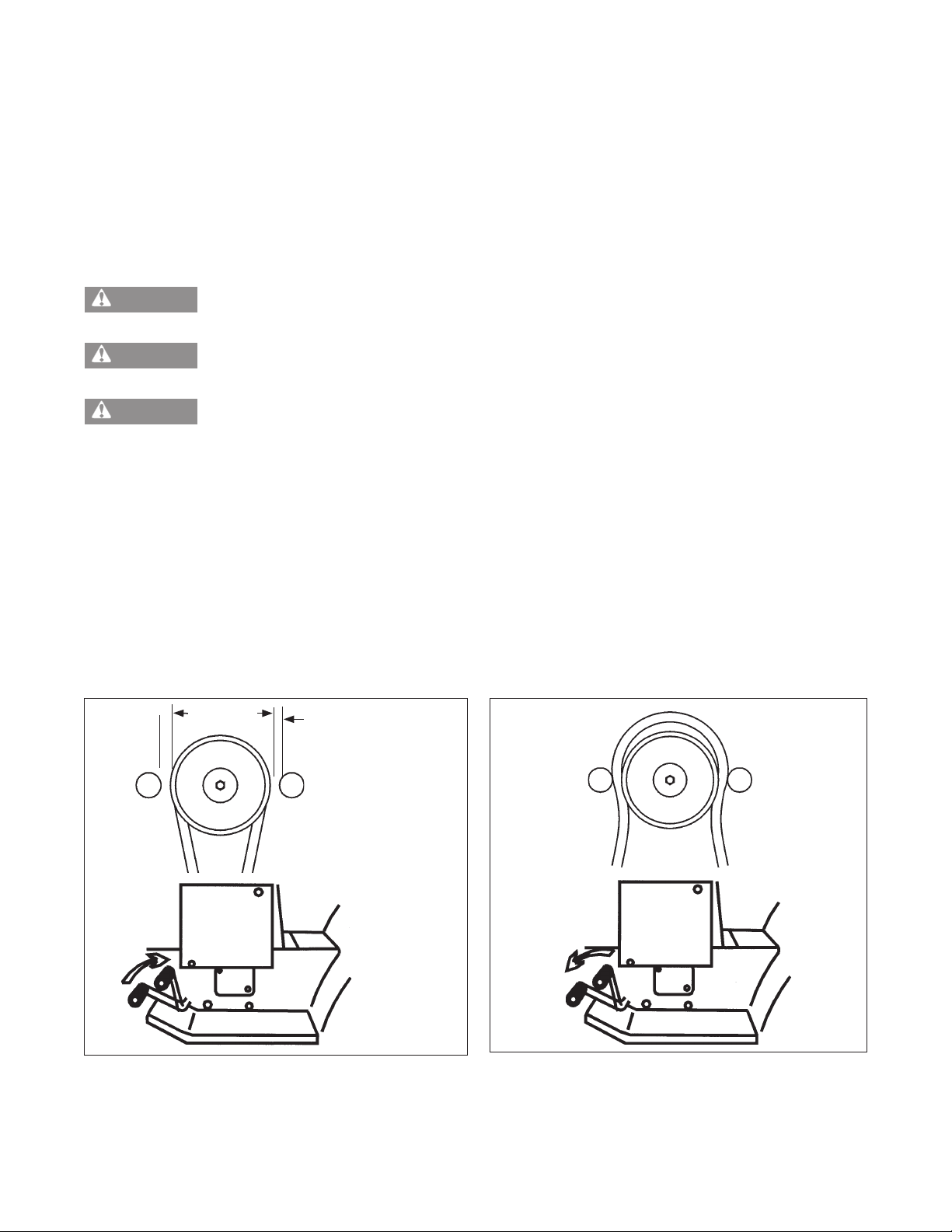
1/16" to 3/16"
(1.6 mm - 4.8 mm)
For proper declutching to occur, it is very important that
the engine belt guide be set at a predetermined clearance
when engaged (set by the manufacturer) and away from
the belt with the belt engaged.
Improper belt or belt guide clearance will not allow the belt to disengage, causing internal transmission
damage.
THIS DIMENSION
VARIES FROM EACH
MANUFACTURER
With clutch disengaged, it is very important that the belt
blossoms away from the engine pulley. Belt must stop
turning before transaxle shifting can occur.
19
Page 23

Basic Gear Drive Troubleshooting - continued
6. Check the brake/clutch pedal to make sure that when the pedal is depressed that the idler pulley is releasing
the belt tension before it applies the brake. If this does not happen the unit will still be under a load and be
impossible to shift.
7. The final area to check would be for damaged or binding shift linkage.
Hard shifting with the engine off could be caused by:
1. Shift linkage out of adjustment.
2. Corrosion in the transaxle or transmission.
3. Damaged shift keys, gears, or shifter brake shaft.
4. Belt guides missing or improperly adjusted (see equipment manufacturer specs).
Unit seems to slip:
1. Check for proper belt adjustment (consult O.E.M. operator's manual).
2. Check for proper clutch/brake adjustment (consult O.E.M. operator's manual).
3. Check pulley condition and wheels for sheared or damaged keys.
4. Check drive belt condition, if glazed or worn, replace it.
5. Possible internal transmission damage. We suggest you contact a local Tecumseh Servicing Dealer.
20
Page 24
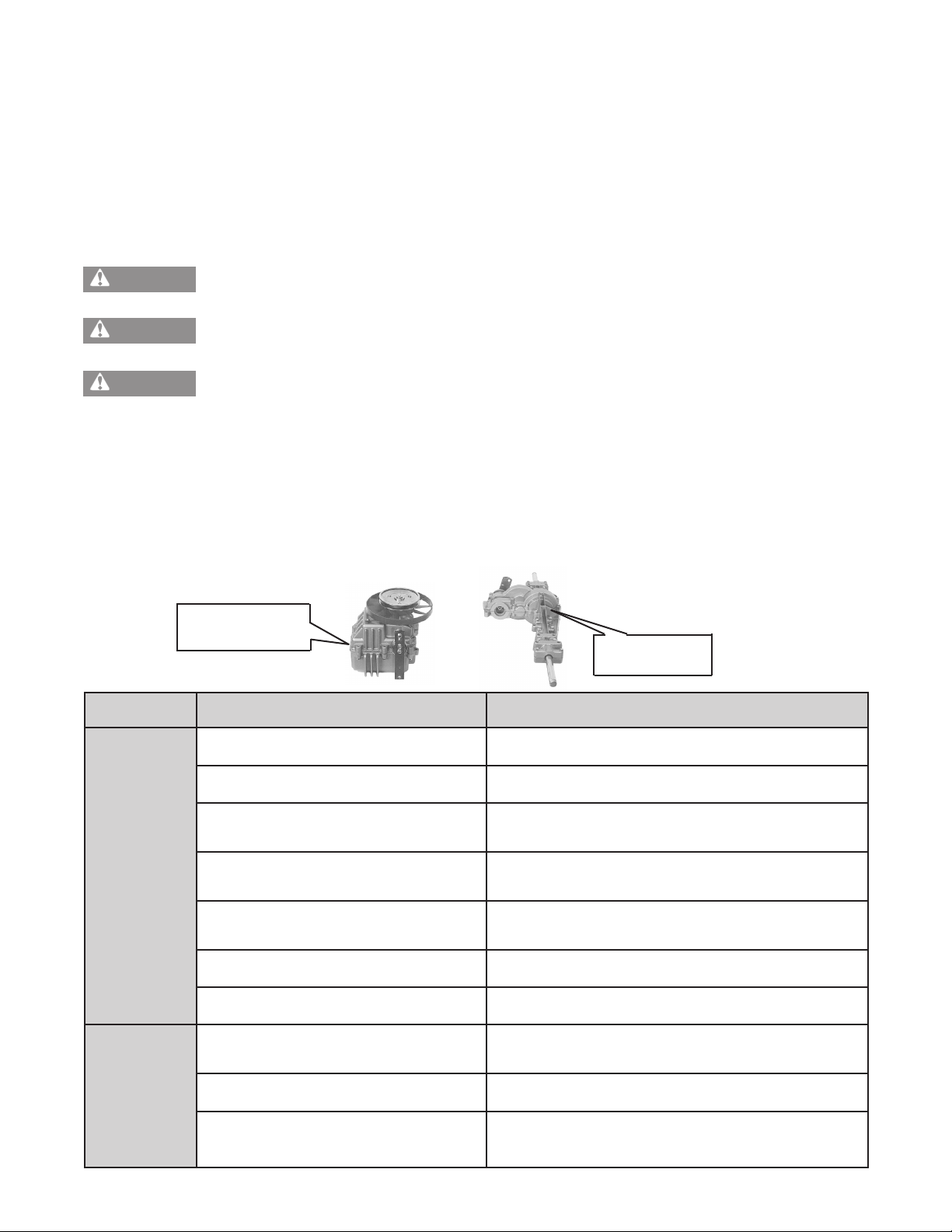
Tecumseh and Peerless Transmission, Transaxle and Gear Products
WARNING
WARNING
WARNING
NOTE
Before troubleshooting any system problem, see original equipment manufacturer’s (O.E.M.) instructions.
Make your troubleshooting easier by preparing as follows:
• Work in a clean, well-lighted place.
• Keep proper tools and materials nearby.
• Keep an adequate supply of clean petroleum-based solvent.
To avoid carbon monoxide poisoning, make sure engine is outdoors in a well-ventilated area.
Some maintenance procedures can not be performed until the vehicle wheels are secured and off
the ground. Failure to do so could result in death or serious injury to yourself and/or bystanders.
DO NOT attempt any maintenance procedures with the engine running. Doing so could result in
death or serious injury to yourself and/or bystanders.
Use care when performing inspection of the drive belt assembly including all vehicle linkage.
Failure to do so could result in death or serious injury to yourself and/or bystanders.
LTH-2000 Series Troubleshooting Chart
Tecumseh’s lawn tractor hydrostatic transaxle (LTH) includes a hydrostatic transmission attached to a final drive.
Use of this troubleshooting chart will aid in determining the source of a problem; the hydrostatic transmission, final
drive or vehicle's belt drive and/or linkage systems.
Tecumseh LTH-2000 Series Hydrostatic Transaxle Troubleshooting
Hydrostatic
ransmission
T
Final Drive
SYMPTOM
Improper belt tension Belt worn, replace
Belt worn, glazed, or oil saturated Replace belt
Drive pulley worn
Brake set too tight
Shifter linkage misadjusted or broken
Fluid low in hydrostatic transmission Check and add fluid if low (Part No. 730228A)
PROBLEM CORRECTIVE ACTION
Replace pulley and belt
(See O.E.M. equipment manual)
Set brake adjustment
(See O.E.M. equipment manual)
Linkage damaged or loose, replace or adjust
(See O.E.M. equipment manual)
REDUCED POWER
Hydrostatic transmission bad Replace hydrostatic transmission
Linkage broken or bent
Hydrostatic transmission pump seized Replace hydrostatic transmission
TO SHIFT
DIFFICULT
Hydrostatic transmission control friction
pack misadjusted
Repair or replace linkage
(See O.E.M. equipment manual)
Replace friction pack washers, tighten nut
to 100 in. lbs. (1
21
1.2 Nm) loosen nut 4-turns
Page 25
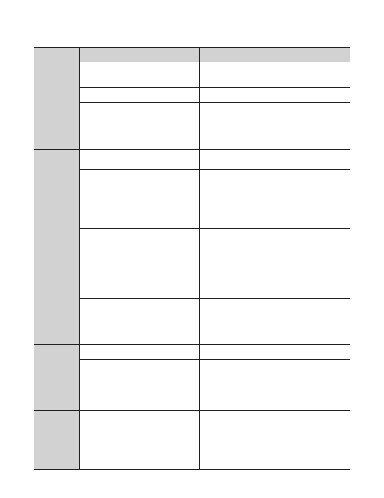
Tecumseh LTH-2000 Series Transaxle Troubleshooting - continued
SYMPTOM
UNIT IS NOISY
PROBLEM CORRECTIVE ACTION
Check, add gear oil to final drive
Final drive gear noise
Hydrostatic transmission noise Replace hydrostatic transmission
Transaxle clicking
Improper belt tension
Brake setting incorrect
Belt worn, glazed, or oil saturated
Drive pulley worn
Transaxle - hydrostatic transmission bad Replace hydrostatic transmission
Check, replace worn gears
Check, replace worn bearings
Mechanical disconnect not properly engaged,
check for obstruction
Check, replace mechanical disconnect
components (If hydrostatic transmission
shaft is damaged, replace transmission)
Belt worn, replace
(See O.E.M. equipment manual)
Adjust brake to proper setting
(See O.E.M. equipment manual)
Replace belt
(See O.E.M. equipment manual)
Replace pulley and belt
(See O.E.M. equipment manual)
Shifter linkage misadjusted or broken
Fluid low in hydrostatic transmission Check and add fluid if low (Part No. 730228A)
DOES NOT DRIVE
LEAKING
Disconnect is in freewheel position
Sheared or missing axle key Replace missing or broken key
Damaged or broken final drive gear Check, replace worn or damaged gear
Hydrostatic transmission leaking Replace hydrostatic transmission
Hydrostatic transmission leaking Replace hydrostatic transmission
Final drive leaking at seam
Final drive leaking at shaft seal
LUBRICANT
Linkage out of adjustment
Linkage damaged or loose, replace or adjust
(See O.E.M. equipment manual)
Move control to connected position
(See O.E.M. equipment manual)
Split final drive housing, clean old sealant off,
replace seals, apply new sealant (torque bolts
80-120 in. lbs.[9.0 Nm - 13.5 Nm])
Split final drive housing, clean old sealant off,
replace seals, apply new sealant (torque bolts
80-120 in. lbs. [9.0 Nm - 13.5 Nm])
Adjust brake linkage
(See O.E.M. equipment manual)
Linkage bent or broken
NOT
BRAKE
Brake setting incorrect
WORKING
Replace components, set brake
(See O.E.M. equipment manual)
Adjust brake to proper setting
(See O.E.M. equipment manual)
22
Page 26

1800 / VST Troubleshooting
The information on this page has been provided to help
understand the internal operation of the VST. Do not
use this information to attempt any internal repairs.
Tecumseh's current policy on hydrostatic transaxles
that have internal failures is to replace the complete
unit. This has not changed. However, Tecumseh would
like to provide a failure checklist to assist in making an
accurate evaluation of the complete tractor to eliminate
any unnecessary replacements. Here is a list of items
to check and corrective actions to take.
To properly test the unit for power loss.
1. Allow the unit to cool before trying the following
steps.
3. Leakage: The VST and 1800 Series have two oil
reservoirs
purposes. The first is the pump and motor expansion
bellows. With a small diameter blunt or round nose
probe, check the bellows depth through the center
vent hole. Proper depth from the edge of that hole
is 3-1/4 - 3-1/2 inches (8.25 - 8.9 cm).
The second chamber is for the output gears
including the differential. FIRST make sure the
tractor is level, then remove the drain/fill plug.
NOTE: Some units that do not have differential
disconnect will have two plugs. We recommend
using only the primary plug. With a small pocket
rule insert until you touch bottom of case. You
can then remove it and check for 1/4 - 3/8 inches
(6.5 - 9.5 mm) contact, this is full at its 8 oz.
capacity.
which can be checked for diagnostic
2. Put the shift lever in a position that is 1/2 of the
travel distance from neutral to forward.
3. Place the tractor on a 17o grade.
4. Drive the tractor up the grade (without the mower
deck engaged). The loss of power experienced
should be approximately 20%. This is considered
normal. If the loss of power is approximately 50%,
this would be considered excessive.
5. Bring the unit to neutral, shift into forward and note
the response. Care should be taken to move the
lever slowly to avoid an abrupt wheel lift.
To determine if the problem is with the hydro unit, all
external problem possibilities must be eliminated. Here
are some potential problem areas.
1. Overheating: Heat can cause a breakdown in the
viscosity of the oil which reduces the pressure used
to move the motor. Remove any grass, debris, or
dirt buildup on the transaxle cover and / or between
the cooling fins and fan. Buildup of material will
reduce the cooling efficiency.
2. Belt slippage: A belt that is worn, stretched, or
the wrong belt (too large or wide) can cause belt
slippage. This condition may have the same loss of
power symptom as overheating. Typically, the unit
which has a slipping belt will exhibit a pulsating type
motion of the mower. This can be verified visually
by watching the belt and pulley relationship. If the
belt is slipping, the belt will chatter or jump on the
pulley. If the belt is good, a smooth rotation will be
seen. Replace the belt and inspect the pulley for
damage.
4. Low ground speed: If the linkage is not
synchronized to absolute neutral, or the shift lever
is not properly fastened to the tapered control shaft,
full forward travel may not be achieved. This may
cause a false reading and be misdiagnosed as a
low power condition. This also could be caused by
the brake not releasing.
To determine absolute neutral, the hole in the
tapered control shaft must face straight up and
down, at this point make sure the O.E.M. linkage is
in neutral. To properly fasten the control lever to the
shaft, torque the nut to 25-35 ft. lbs. (34 - 48.3 Nm)
of torque with the shaft and the lever in neutral.
When attaching the shifter arm to the shaft you
must prevent any rotation during torquing. This can
be done by placing a long 5/16" bolt in the hole of
the shaft. Hold the bolt until the tapers are locked
and the nut torque is correct.
To make sure that the brake is not binding, drive the
unit up a slight grade. Position the speed control
lever into neutral. The unit should coast backwards.
If the unit does not coast back slowly, the brake is
not released from the brake disk. Adjust the brake
linkage to release the brake completely when the
foot pedal is released.
5. Hard to shift: Typically hard to shift symptoms are
not caused by the hydrostatic unit. The shift arm
should move with relative ease. Approximately 4050 in. lbs. (4.48 - 5.6 Nm) at the transaxle for foot
pedal units or 150-200 in. lbs. (16.8 -22.4 Nm) for
hand operated units. This varies depending on the
type of linkage. Binding may occur in the linkage
connections due to rust or moisture. Lubricating
these connections and checking for bent or
damaged parts should resolve hard shifting.
23
Page 27
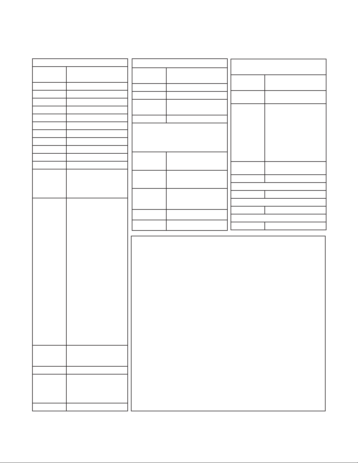
Tecumseh and Peerless® Lubrication Requirements
NOTE
Use ONL
Y the recommended lubricant in all models as listed to insure proper operation and long life.
TRANSAXLES
Model
No.
301 Non-Serviceable
600 24 oz./710 ml Oil
800 30 oz./887 ml Grease
801 36 oz./1065 ml Grease
820 36 oz./1065 ml Grease
900 26 oz./769 ml Grease
910 18 oz./532 ml Grease
915 10 oz./296 ml Grease
920 30 oz./887 ml Grease
930 30 oz./887 ml Grease
1200 48 oz./1420 ml Oil ††
1301
1305
1309
1313
1302
1303
1304
1306
1307
1308
1310
131
1
1312
1314
1315
1316
1317
1318
1319
1320
1321
1322
1325
1328
1329
1323
1326
1327
MST200 16 oz./473 ml Oil
VST205
and
1800's
2300
2400 32 oz./946 ml Oil
Quantity
32 oz./946 ml Oil
44 oz./1301 ml Oil
24 oz./710 ml Oil
††††
64 oz./1892 ml Oil
TRANSMISSION
Model
No.
2500 †
2600 †
700
700H
2800 †
Quantity
12 oz./355 ml Grease
12 oz./355 ml Grease
HYDROSTATIC
TRANSAXLES and
TRANSMISSIONS
1800 Series
VST205/705
L
TH 2000
2100 Non-Serviceable
LDP-10 Non-Serviceable
Limited service; use
Kit Part No. 799030
Limited service; use
Kit Part No. 799030
Limited service;
final drive ONL
8 oz./240 ml Oil
Y
Model
No.
All Models
Except *
*1408-P91
*1409-P91
*1410-P91
*3002
*3003
*3028
*3029
*3035
1000 Series
1
100 16 oz./473 ml Oil
All Models 3 oz./89 ml Grease
All Models 2 oz./59 ml Grease
All Models 2 oz./59 ml Grease
RIGHT ANGLE
AND T-DRIVES
Quantity
4 oz./1
18 ml Grease
3 oz./89 ml Grease
6 oz./180 ml Oil
†††
DIFFERENTIALS
TWO SPEED AXLE
THREE SPEED AXLE
Grease: Bentonite Grease
Part Number 788067C
Oil: SAE E.P. 80W90 Oil
Part Number 730229B
† Refer to O.E.M. Technician’s Manual for type of lubricant.
†† To be filled through shift lever opening.
††† Some 1000 Right Angle and T-Drives use Bentonite Grease.
†††† Tecumseh's current policy on VST and 1800 Series transaxles
with internal failure, is to replace the complete unit. VST and 1800's
have two separate reservoirs which can be checked for diagnostic
purpose only. The output gear reservoir can be checked with a small
pocket rule as outlined in the Tecumseh & Peerless Transmission and
Drive Products Handbook.
Refer to Tecumseh & Peerless Transmission and Drive Products
Handbook, 691218.
24
Page 28
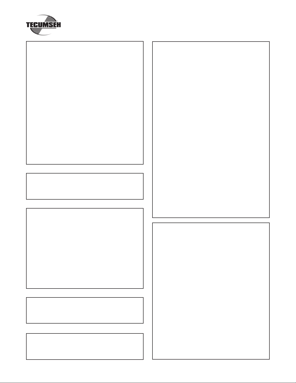
Repair Manuals
Service Number 740043 or 695244A
†
OHM120
‡
OH318SA (OHSK110), OH358SA (OHSK120-130)
OH318EA (OHM90-110)
†
OHM120
OH195EA (OHH60), OH195EP (OHH65)
OHH/OHSK40-130
OH195SA (OHSK70), OH195SP (OHSK75)
‡
OH318SA (OHSK110), OH358SA (OHSK120-130)
OVM120
* OVXL120,
* OVXL/C120
* OVXL125
OV195EA
OV358EA (OHV110-135)
OV490EA (OHV140-180)
OV691EP (VTX691, TVT691)
OVM120
* OVXL120
* OVXL/C120
* OVXL125
Service Number 691462A
HH140-160
OH120-180
Service Number 740047 or 692508
AH520
AH600
HSK840
HXL840
TC200
TCH200 Type 1500
TH098SA (HSK600), HSK635
TH139SA (HSK845, 850)
TH139SP (HSK870)
AV600
TV085XA (AV520)
TVS600
Service Number 694988
TVS840
TVXL840
Service Number 694782
TCH300
TM049XA (TC300)
Service Number 740049 or 692509
ECV100-120
HMSK70, LH318SA (HMSK80), HMSK90,
H22
H25
H30-80
HM70-100
HH40-120
HHM80
HMXL70
HT30
HT35
HXL35
HS40-50
HSK30-70
HSSK40, LH195SA
LH358SA (HMSK100), HMSK110
LAV25-50
LEV80, LV148EA (LEV90), LV195EA (LEV120)
LV148SA (VSK90), VSK100
TNT100
TNT120
TVS75-120
TVXL90-120
TVM125-170
TVM195-220
TVXL195-220
V40-80
VH40-100
VM70-100
VL
V-ALL
(HSSK50), LH195SP (HSSK55)
Service Number 740045 or 691218
100 Series Differentials
MST200 Series Transaxles
300 Series Transaxles
600 Series Transaxles
601 Slow Speed Transaxle
700 Series Transmissions
700H Series Transmissions
800/801 Series Transaxle
820 Series Transmission
900 Series Transaxles
910 Series Transaxles
915/940 Series Transaxles
920 Series Transaxles
930 Series Transaxles
1000/1100 Series Right Angle / T-Drives
1200 Series Transaxles
1300 Series Transaxles
2300 Series Transaxles
2400 Series Transaxles
2500 Series Transaxles
2600 Series Transaxles
VST Transaxles
25
Page 29

Form No. 696533 Litho In U.S.A. R 11/05
TECUMSEH POWER COMPANY
900 North Street
Grafton, Wisconsin 53024
1-800-558-5402
26
 Loading...