

Tecumseh ROTARY COMPRESSORS HG, ROTARY COMPRESSORS RG, ROTARY COMPRESSORS RK, RK, RG Installation And Operation Manual
...
MANUAL
INSTALLATION AND OPERATION
Rotary Compressors
RK, RG and HG

2
General Information 5
The working principle of the Rotary Compressor 5
Range 6
Performance 7
Voltage and range of operation 7
1.4.1 Single phase 7
1.4.2 Three phase 7
Dimensions and connections 8
Mountings 8
Oil type 8
1
1.1
1.2
1.3
1.4
1.5
1.6
1.7
Operating Range 9
Operating envelope 9
Operating compression ratio 9
Operating pressure differential 9
2
2.1
2.2
2.3
Temperature Criteria 10
Ambient temperature 10
Discharge temperature 10
Motor temperature 10
Return gas temperature 10
3
3.1
3.2
3.3
3.4
General Recommendations 11
System requirements 11
Pipework design 11
4.2.1 Pipework design advice/guidance 11
4.2.2 Connections 14
4.2.3 Flexible connections 14
4.2.4 Velocity within pipework and heat exchangers 14
4.2.5 Capillaries 16
Refrigerant charge 21
4.3.1 Advice for installers 21
4.3.2 Refrigerant charge 21
Starting 21
4.4.1 Frequency of starts 21
4.4.2 Start-up pressure 21
4
4.1
4.2
4.3
4.4

3
Security 23
Pressure 23
Electrical 23
Declaration of incorporation 23
5
5.1
5.2
5.3
Appendices 25
Documents 25
Contacts 25
6
6.1
6.2
General Recommendations (continued)
Liquid return whilst operating 22
Liquid migration during prolonged shutdown 22
4.6.1 Band heaters 22
4.6.2 Non-return valves 22
Purging refrigerant from the system 22
4
4.5
4.6
4.7

General Information
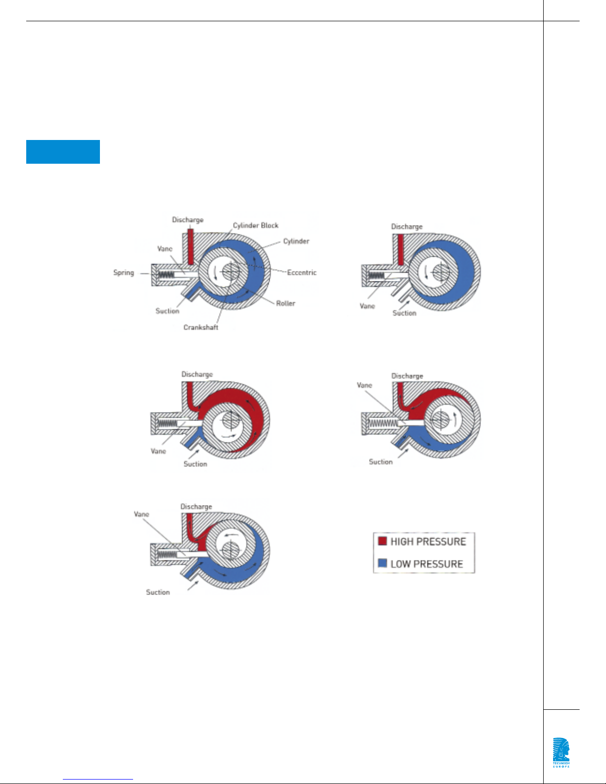
The working principle of the Rotary Compressor
Rotary compressors are ‘high pressure shell’ type compressors. The suction on these compressors
is taken directly into the compression chamber. Gas compressed in the compression chamber is
discharged into the compressor casing. It should be noted that from a cold start-up, high pressure shell
type compressors take longer to reach their normal operating pressure in the compressor shell. This
is partly due to the larger volume of the compressor casing and partly as a result of refrigerant being
trapped in the oil. Any refrigerant in the oil has to completely evaporate before condensing pressure can
reach its operating level.
1
1.1
5
Tecumseh Europe with its long experience of compressor development has introduced
a range of rotary compressors for air conditioning and commercial refrigeration.
This operating manual has been designed to help you correctly install this compressor
range in your applications.
1|Names of the different pieces 2|End of suction and the start of compression
3|Start of compression and suction 4|Compression and suction
5|Compressed gas exit
6
1.2
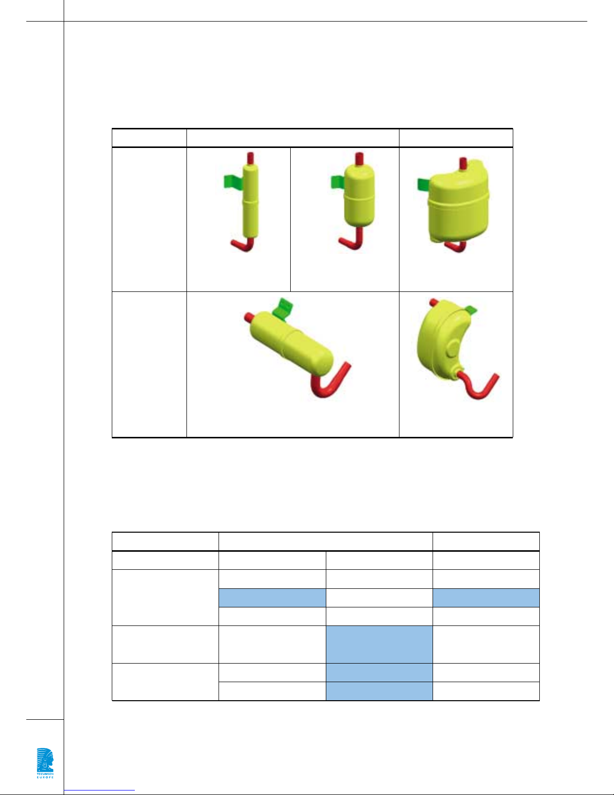
Sucking bottle
Excessive refrigerant, oil or impurity in the suction chamber of the compressor can result in mechanical
damage. As a result, all our compressors are fitted with an accumulator equipped with a filter.
Please note that overcharging with refrigerant is one of the major causes of damage to the compressor.
It is important to check the amount of refrigerant being used is correct.
Range
Application
VERTICAL HORIZONTAL
Air Conditioning
or Heat Pump
RG range, accumulator
capacity > 100 cm
3
RK range, accumulator
capacity > 160 cm
3
RG range, accumulator
capacity > 680 cm
3
HG range, accumulator
capacity > 405 cm
3
HG range, accumulator capacity > 70 cm
3
Commercial Refrigeration
Low Back Pressure
RG RK HG
R22 R22 R22
R134a
R407C R407C R407C
Commercial Refrigeration
High Back Pressure
R134a R134a
R404A R404A
VERTICAL
AIR CONDITIONING COMMERCIAL
HORIZONTAL
R404A R404A
7
Performance
Please refer to the Technical Data Sheets for information on compressor performance.
Voltage and range of operation
The voltage range of the rotary compressors corresponds to the standard ranges defined by Tecumseh
Europe. See the General Catalogue for more information.
Start-up should never be carried out when the electrical cover has been removed.
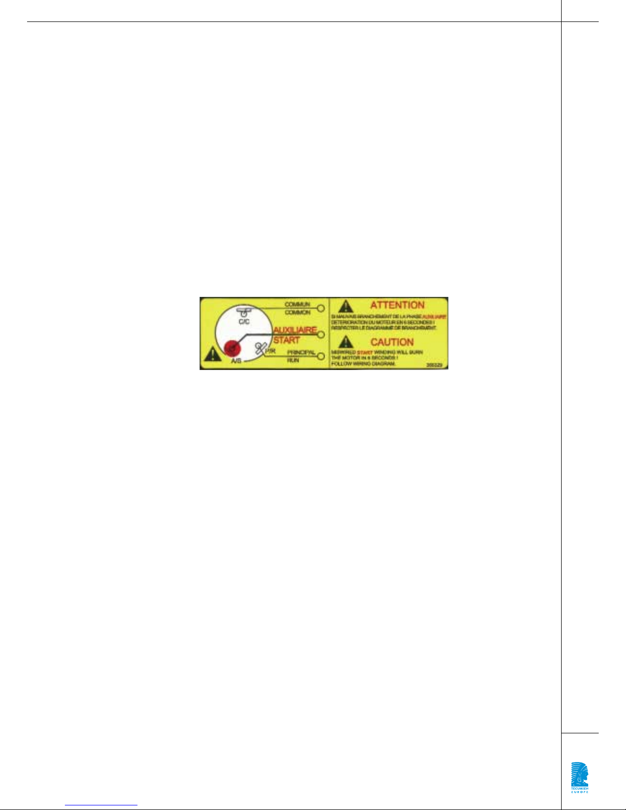
1.4.1 Single phase
Single phase compressor motors are two pole asynchronous and they are designed to be used with
different types of starting method depending on the application (PSC, CSR, CSIR).
Please ensure the starting mode follows that specified on the Technical Data Sheet for each product.
We recommend the use of components specified by Tecumseh Europe.
For wiring instructions, follow the diagram supplied with the compressor.
Ensure that the start and run windings are connected correctly otherwise damage to the motor will
result (see label below).
1.4.1.1 Motor protection
The motor is protected by an externally mounted temperature and current sensitive overload. It is imperative that the overload protector is connected as it cuts off the power supply to the compressor if a fault
occurs. For wiring instructions, follow the wiring diagram supplied with the compressor.
1.4.2 Three phase
All rotary compressors which have a model number beginning with a letter ‘T’ are equipped with a three
phase motor.
Three phase motors are wired in star, and the resistance measured between two terminals corresponds
to the resistance of that coil.
Ensure that each compressor conforms to the information given on the Technical Data Sheet.
We recommend the use of components specified by Tecumseh Europe.
For wiring instructions, follow the diagram supplied with the compressor.
1.4.2.1 Phase control
Care should be taken when connecting three phase rotary compressors to ensure that the direction of
rotation is correct as rotation occurs in one direction only.
ATTENTION: If the rotational direction is incorrect, the compressor will not refrigerate and the life of the
product will be reduced. However, a short test period will not cause damage.
To ensure correct rotation we recommend the use of our phase detector reference number 8 535 136,
which is listed in our Spare Parts and Accessories Catalogue.
1.4.2.2 Protection of the motor
The motor is protected from overheating by an external overload protector which must be connected.
This device has a single contact and cannot be wired into the three phase electrical supply of the compressor (a three phase motor can only operate with a minimum of 2 active phases). The protector should
therefore be wired into the control circuit of the compressor so that it cuts the power supply if a fault
occurs. For wiring instructions, see the electrical diagram supplied with the compressor.
For further information on protecting the compressor against high current, please contact the technical
application department at Tecumseh Europe.
1.3
1.4
8
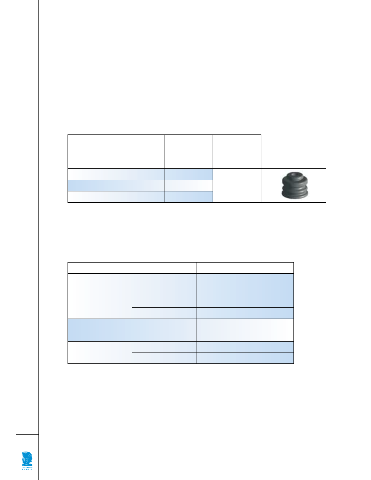
RG
STANDARD
MOUNTING
STANDARD
PLAY
HG
4 feet 8 682 025
3 feet 8 682 021
RK
1.5
1.6
1.7
RANGE
MAXIMUM
TORQUE
SETTINGS
3 feet 8 682 021
13.8 Nm to 17.9 Nm
(10 to 13 ft.lbs)
Air Conditioning
or Heat Pump
REFRIGERANT OIL
APPLICATION
R22 Alkyl Benzene
R134a Polyolester
R404A Polyvinyl ether
R134a Polyolester
R404A Polyvinyl ether
Commercial Refrigeration
Low Back Pressure
Commercial Refrigeration
High Back Pressure
Short pipe run* (<3,6m): Alkyl Benzene
Long pipe run* (≥3,6m): PVE
R407C
Dimensions and connections
The dimensions and the position of the connections are given in our Technical Data Sheets.
The compressors can tolerate an angle of tilt of +/- 7° for vertical models and +5°/0° for horizontal versions.
Mountings
We recommend the fitting of anti-vibration mounting feet as specified by Tecumseh Europe (see table
below).
Natural or synthetic rubber products bearing weight for long periods tend to loose their shape. This
occurs more quickly when they are subject to an excessive loading and/or heat. Anti-vibration mounting
feet should be regularly checked to ensure optimal operation of the installation and replaced where
necessary to ensure the sound level does not increase.
The length of the AV mount insert used allows the mounts to function correctly and prevents overtightening.
Specific mounts can be supplied for applications where greater vibration reduction is required. For further
information, contact your local representative.
Oil type
* Short or long pipe run: Distance between the condenser and the evaporator.
The design of the rotary compressors is such that an oil change or the addition of oil should not be
carried out.
We strongly advise against adding oil to the refrigeration system whether the pipework is long or short.

9
Operating Range
Operating envelope
The operating envelope is in accordance with EN 12 900, with a superheat of 10K for air conditioning
and heat pump applications, and return gas of 20°C for all other applications (See diagrams in
the appendices).
For more information please refer to the Technical Data Sheet for each product.
Operating compression ratio
The operating compression ratio is the ratio between absolute condensing and evaporating pressures.
It is essential to adhere to the maximum values listed in the following table.
Exceeding these values will reduce the working life of the compressor or even cause a breakdown.
Operating pressure differential
The operating pressure differential corresponds to the difference between absolute discharge and suction pressure. Maximum levels are listed in the table below. Exceeding these values will reduce the working life of the compressor or even cause a breakdown.
2
2.1
2.2
2.3
Air Conditioning
or Heat Pump
REFRIGERANT COMPRESSION RATIO
APPLICATION
R22 7
R134a 15.8
R407C 7
R404A 8
R134a 15.8
R404A 22
Commercial Refrigeration
Low Back Pressure
Commercial Refrigeration
High Back Pressure
Air Conditioning
or Heat Pump
REFRIGERANT PRESSURE DIFFERENTIAL (BAR)
APPLICATION
R22 22
R407C 23.5
R134a 23
R404A 25
R134a 23
R404A 27.1
Commercial Refrigeration
Low Back Pressure
Commercial Refrigeration
High Back Pressure

10
Temperature Criteria
Ambient temperature
The compressors have been designed to operate in the following ambient temperatures (with forced
air cooling).
Comment:
For air conditioning applications operating in high ambient conditions, see our tropical range. These
products use R-134a and have an evaporating temperature range of –10°C to +30°C, and a condensing
temperature range of +30°C to +80°C for a temperature of 55°C.
Discharge temperature
The maximum discharge temperature is 127°C. This temperature can be measured by soldering a
thermocouple onto the discharge pipe 5 cm from the compressor and insulating it for 10 cm.
Motor temperature
All our single phase rotary compressors are supplied with an external overload protector. The maximum
permitted operating temperature is 130°C which is measured by the resistance variation method.
Resistance variation method: Leave the application switched off in a constant temperature
(temperature t1) for at least 8 hours. Measure the motor winding resistance R1at this temperature t1.
With three phase motors, measure the resistance between 2 electrical supply terminals to the compressor.
Run the application in the most difficult conditions foreseeable, switch off the machine and immediately
measure the new motor winding resistance (R2). With three phase motors, measure the resistance
between the 2 terminals used before.
The new temperature t2can easily be calculated using the following equation:
t1& t2are given in degrees Celsius.
Return gas temperature
A minimum superheat of 10K is necessary between the evaporating temperature and suction temperature
at the inlet of the compressor. However, it is necessary to control superheat to prevent exceeding the
maximum return gas temperature for the compressor and the compressor motor (see sections 3.2 and 3.3).
3
3.1
3.2
3.3
3.4
Air Conditioning
or Heat Pump
AMBIENT TEMPERATURE
46°C
43°C
Commercial Refrigeration

11
General Recommendations
System requirements
Rotary compressors are ‘direct suction’. The suction gas enters directly into the compression chamber.
The suction accumulator incorporates a filter to protect the compressor against dirt and debris entering
the pump.
It is essential that all necessary precautions are taken to ensure the system is kept clean during
installation and service e.g. purge the system with Nitrogen whilst brazing.
Pipework design
The function of the pipework is to allow the refrigerant to circulate through the system components in
such a way as to provide optimum operating conditions, i.e.:
> Limited pressure drop,
> Velocity is sufficient to entrain the oil,
> Ensure that the compressor is protected against the return of liquid refrigerant particularly when
the installation is switched off.
> A full head of liquid refrigerant at the expansion device.
As in all refrigerating systems using hermetic compressors, some of the oil from the compressor
circulating within the system is entrained with the refrigerant. The amount varies according to the operating conditions of the installation. No additional components e.g. oil separator, oil coolers etc. are
required to assist with oil control in rotary compressor systems.
However, it is essential to ensure the oil return to the compressor otherwise its working life may be
shortened and its performance affected.
All pipework in the refrigerating system must be designed to return oil to the compressor. The design
must prevent oil being trapped in the pipework, the system components and the heat exchangers.
Refrigeration best practice must be respected.
Due to the difficulty of controlling the return of oil in a multi-evaporator system, we advise that the
rotary compressors should only be used in a single circuit system.
4.2.1 Pipework design advice/guidance
4.2.1.1 Suction pipework
Suction pipework returns refrigerant gas to the compressor from the evaporator. The main factors
to consider are:
> A partial refrigerant charge caused by a leak or incomplete charging will cause a reduction in
compressor capacity due to the lower suction pressure,
> Reduce the return gas superheat in order to limit the discharge temperature,
> Ensure that the refrigerant velocity is sufficient to return the oil to the compressor which has a small
oil charge,
> Prevent refrigerant entering the compressor during either the running or off cycles. The possibility
of any liquid slugs of oil entering the compressor during the running must also be prevented.
In practice, suction lines are generally designed for pressure drops of no more than 1°C saturated temperature.
4
4.1
4.2

12
1 - If the compressor is located higher than the
evaporator, the oil return to the compressor must
be guaranteed. Oil traps at the beginning of the
suction risers must be used and the pipe line velocity must be sufficient to ensure oil flow in suction
risers. A smaller size oil trap could be used before
the suction riser.
2 - When the compressor is on the same level or
lower than the evaporator, we recommend that
swan neck suction line is used where the top of the
swan neck is above the evaporator, whether the
suction exit of the evaporator is at the top or bottom.
This is to prevent the gravitational flow of refrigerant to the compressor during the off cycle.
On the other hand, an oil trap should not be used
close to the suction of the compressor to prevent
oil/refrigerant slugs (or a mixture of both) reaching
the compressor.
3 - The above design can be simplified by using a
“pump down” control system.
This system requires the installation of a solenoid
valve (LLSV) prior to the expansion device (EXV).
The compressor is controlled by a low pressure
switch. Before pump down can occur, the solenoid
valve must be closed in order to pump out the evaporator and transfer the refrigerant to the high
pressure side. As the low pressure in the suction
reaches the cut off point of the low pressure switch,
the pressure switch stops the compressor.
Liquid cannot therefore accumulate at the suction
of the compressor.
The suction piping then drops directly towards the
compressor.
4.2.1.1.1 Discharge pipework
The discharge pipework carries refrigerant gas compressed by the compressor to the condenser.
The main factors to consider are:
> Minimum pressure drop,
> The velocity is sufficient to take the oil to the condenser even when there is only a partial charge,
> Ensure that liquid (oil, refrigerant or both) does not migrate towards the compressor during the off cycle.
In practice, discharge piping can be designed for a pressure drop of up to 1°C at saturation temperature.
Pressure drop in the discharge pipework can cause a slight reduction in capacity as the compressor has
to operate at a discharge pressure higher than the condensing pressure.
Riser
Suction pipework
Pump down

13
If the installation is such that the compressor is
the coldest part of the system (i.e. has the lowest
temperature), a non-return valve must be fitted
close to the condenser to isolate the condenser
from the compressor.
The valve is also an advantage during start-up
where a large pressure differential may occur.
(see § 4.4.2)
4.2.1.1.2 Liquid pipework
The liquid line supplies liquid refrigerant to the expansion device from the condenser/receiver. When
sizing a liquid line the main factors to consider are:
> The re-heating of the duct,
> Minimum pressure drop.
In this part of the system, because the oil and refrigerant are miscible, oil flow does not present any
particular problems. However, attention must be paid to ensuring there is a constant supply of liquid to
the expansion device. Under no circumstances must the refrigerant be heated and pressure changes in
the pipework must be prevented.
If liquid refrigerant experiences a pressure below its saturation pressure, it will vaporize within
the pipework.
To ensure the expansion device functions correctly, the pressure of the liquid reaching it must be sufficiently high, and preferably, slightly subcooled. It is essential to restrict the pressure drop in the pipework for the following reasons:
> To prevent a reduction in the mass flow through the expansion device,
> To prevent partial vaporization of the liquid refrigerant prior to the expansion device (pressure drop
higher than subcooling).
The components fitted to the liquid line such as the filter drier, solenoid valve, liquid line sight glass also
cause varying pressure drops.
The pressure drop in this pipework must not exceed 0.5°C.
4.2.1.1.3 Positioning of accessories on the liquid line
The diagrams below show the normal position of accessories on the liquid line.
The filter drier must be positioned next to the
expansion device to prevent clogging by impurities.
It should be installed in a vertical position with the
outlet downwards to ensure constant liquid supply
to the expansion device.
The liquid sight glass should be positioned between
the drier and the expansion device in order to indicate that:
> Liquid / vapour is present,
> The level of risedual humidity.
Discharge pipework
Liquid line - position of accessories

4.2.2 Connections
The rotary compressors have copper connections. The positioning of connections is given in the
Technical Data Sheets. Please note the following:
• Brazing should be carried out using an inert gas (Nitrogen).
• Protect paintwork while brazing by covering the accumulator and compressor with a damp cloth.
Do not allow the flame to come in contact with paintwork.
• Brazing of the connections must comply with the recommendations of the Standard NF EN 378-2.
• Carry out pipe cutting and bending operations carefully in order to prevent dust and swarf contaminating
the system.
Care should be taken to ensure that flux does not contaminate the system.
4.2.3 Flexible connections
Rotary compressors do not have internal mounting springs, in contrast to the majority of hermetic compressors. The internal design and external mountings are designed to reduce vibration. However, some
vibration is transmitted to the suction and discharge pipework. We therefore recommend using flexible
connections to prevent vibration being transmitted to the rest of the installation.
We recommend using annealed copper pipe rather than hard drawn.
A suggested design of flexible connections for this range of compressors and their applications is
shown in the diagrams in the Appendices (see p. 25).
The general design of the pipework can be adjusted according to your equipment. The recommended
suction loop of 3/8 inch and 1/4 inch discharge should be adhered too.
Great care should be taken when designing the system and correct refrigeration practices must be followed to ensure the oil return to the compressor.
4.2.4 Velocity within pipework and heat exchangers
To ensure correct running of the installation and to assure the working life of the compressor, it is
recommended that pipework be calculated using the velocities shown in the table below.
Anti-vibration loops are used to provide a very flexible pipework system which absorbs vibration. The velocity
in the AV loops should not exceed that stated in the table.
A minimum velocity of 8 m/s is necessary in any vertical risers, suction or discharge to ensure adequate
oil return to the compressor.
The velocity within the heat exchangers should not drop below 3 m/s to guarantee oil return.
The table page 21 lists the velocities for different internal diameter pipework and compressor models.
The choice of pipework should therefore be made for a particular model of compressor and specified
type of connection (suction, discharge or liquid pipework) in accordance with the velocity ranges recommended in the above table.
In the case of the heat exchangers, the number of circuits can be defined on the basis of the refrigerant
velocity circulating in the tubes, taking as reference the value calculated at the suction for the evaporator
and at the discharge for the condenser.
14
Connections
SUCTION DISCHARGE
LIQUID
Minimum Maximum Minimum Maximum Minimum Maximum
25 m/s 25 m/s
4 m/s 15 m/s 4 m/s 15 m/s 0.3 m/s 1 m/s
3 m/s 10 m/s
3 m/s 8 m/s
Anti-vibration loops
Pipework
Evaporator
Condenser

15
Refrigerant velocity in the suction pipework (in m/s)
HG/RG2426Z
HG/RG2432Z
HG/RG2436Z
HG/RG2446Z
HG/RG4467Z
HG/RG4480Z
68
Suction Discharge Liquid
10 12 14 16 3 5 7 9 11 3 5 7 9 11
CAPILLARY - INTERNAL DIAMETER (mm)
13.7 7.7 4.9 3.4 2.5 1.9 6.7 2.4 1.2 0.7 0.5 0.61 0.22 0.11 0.07 0.05
16.2 9.1 5.8 4.1 3.0 2.3 7.9 2.8 1.5 0.9 0.6 0.73 0.26 0.13 0.08 0.05
17.9 10.1 6.4 4.5 3.3 2.5 8.7 3.1 1.6 1.0 0.6 0.80 0.29 0.15 0.09 0.06
23.3 13.1 8.4 5.8 4.3 3.3 11.3 4.1 2.1 1.3 0.8 1.04 0.38 0.19 0.12 0.08
14.6 8.2 5.2 3.6 2.7 2.0 18.5 6.6 3.4 2.1 1.4 1.70 0.61 0.31 0.19 0.13
17.4 9.8 6.3 4.3 3.2 2.4 22.1 7.9 4.1 2.5 1.6 2.03 0.73 0.37 0.23 0.15
19.9 11.2 7.2 5.0 3.7 2.8 25.3 9.1 4.6 2.8 1.9 2.32 0.84 0.43 0.26 0.17
24.7 13.9 8.9 6.2 4.5 3.5 31.3 11.3 5.7 3.5 2.3 2.88 1.04 0.53 0.32 0.21
14.2 8.0 5.1 3.6 2.6 2.0 16.0 5.7 2.9 1.8 1.2 0.66 0.24 0.12 0.07 0.05
17.2 9.7 6.2 4.3 3.2 2.4 19.3 7.0 3.5 2.1 1.4 0.80 0.29 0.15 0.09 0.06
19.2 10.8 6.9 4.8 3.5 2.7 21.6 7.8 4.0 2.4 1.6 0.90 0.32 0.16 0.10 0.07
25.0 14.1 9.0 6.2 4.6 3.5 28.1 10.1 5.2 3.1 2.1 1.17 0.42 0.21 0.13 0.09
18.1 10.2 6.5 4.5 3.3 2.6 21.2 7.6 3.9 2.4 1.6 1.05 0.38 0.19 0.12 0.08
29.8 16.7 10.7 7.4 5.5 4.2 34.7 12.5 6.4 3.9 2.6 1.72 0.62 0.32 0.19 0.13
38.3 21.6 13.8 9.6 7.0 5.4 44.8 16.1 8.2 5.0 3.3 2.21 0.80 0.41 0.25 0.16
17.6 9.9 6.3 4.4 3.2 2.5 21.5 7.7 3.9 2.4 1.6 1.53 0.55 0.28 0.17 0.11
19.8 11.1 7.1 5.0 3.6 2.8 24.2 8.7 4.4 2.7 1.8 1.72 0.62 0.32 0.19 0.13
22.3 12.5 8.0 5.6 4.1 3.1 27.3 9.8 5.0 3.0 2.0 1.94 0.70 0.36 0.22 0.14
24.5 13.8 8.8 6.1 4.5 3.5 30.0 10.8 5.5 3.3 2.2 2.13 0.77 0.39 0.24 0.16
17.7 10.0 6.4 4.4 3.3 2.5 21.7 7.8 4.0 2.4 1.6 1.54 0.56 0.28 0.17 0.11
19.2 10.8 6.9 4.8 3.5 2.7 23.5 8.4 4.3 2.6 1.7 1.67 0.60 0.31 0.19 0.12
23.0 12.9 8.3 5.7 4.2 3.2 28.1 10.1 5.2 3.1 2.1 2.00 0.72 0.37 0.22 0.15
24.5 13.8 8.8 6.1 4.5 3.5 30.0 10.8 5.5 3.3 2.2 2.13 0.77 0.39 0.24 0.16
27.9 15.7 10.0 7.0 5.1 3.9 34.1 12.3 6.3 3.8 2.5 2.43 0.87 0.45 0.27 0.18
34.0 19.1 12.2 8.5 6.2 4.8 41.5 14.9 7.6 4.6 3.1 2.96 1.06 0.54 0.33 0.22
38.9 21.9 14.0 9.7 7.1 5.5 47.6 17.1 8.7 5.3 3.5 3.39 1.22 0.62 0.38 0.25
17.7 10.0 6.4 4.4 3.3 2.5 24.0 8.6 4.4 2.7 1.8 1.54 0.55 0.28 0.17 0.11
19.8 11.1 7.1 4.9 3.6 2.8 26.7 9.6 4.9 3.0 2.0 1.72 0.62 0.32 0.19 0.13
21.0 11.8 7.6 5.3 3.9 3.0 28.4 10.2 5.2 3.2 2.1 1.83 0.66 0.34 0.20 0.14
24.9 14.0 9.0 6.2 4.6 3.5 33.7 12.1 6.2 3.7 2.5 2.16 0.78 0.40 0.24 0.16
17.3 9.7 6.2 4.3 3.2 2.4 23.4 8.4 4.3 2.6 1.7 1.50 0.54 0.28 0.17 0.11
19.9 11.2 7.2 5.0 3.7 2.8 26.8 9.7 4.9 3.0 2.0 1.72 0.62 0.32 0.19 0.13
22.6 12.7 8.1 5.7 4.2 3.2 30.6 11.0 5.6 3.4 2.3 1.96 0.71 0.36 0.22 0.15
25.0 14.1 9.0 6.2 4.6 3.5 33.7 12.1 6.2 3.7 2.5 2.17 0.78 0.40 0.24 0.16
27.9 15.7 10.0 7.0 5.1 3.9 37.6 13.5 6.9 4.2 2.8 2.42 0.87 0.44 0.27 0.18
32.4 18.2 11.7 8.1 6.0 4.6 43.8 15.8 8.0 4.9 3.3 2.81 1.01 0.52 0.31 0.21
37.9 21.3 13.6 9.5 7.0 5.3 51.1 18.4 9.4 5.7 3.8 3.29 1.18 0.60 0.37 0.24
HG/RG4492Z
HG/RG4512Z
HG/RG4445Y
HG/RG4450Y
HG/RG4460Y
HG/RH4476Y
RK5450Y
RK5480Y
RK5512Y
RGA5480C
RGA5492C
RGA5510C
RGA5512C
RK5480C
RK5490C
RK5512C
RK5510C
RK5515C
RK5513C
RK5518C
RGA5480E
RGA5492E
RGA5510E
RGA5512E
RK5480E
RK5490E
RK5510E
RK5512E
RK5513E
RK5515E
RK5518E

16
4.2.5 Capillaries
Capillaries are currently used as expansion devices in small refrigeration installations as they are:
> Easy to use,
> Inexpensive,
> Reliable: there are no moving parts,
> Permits the use of low starting torque compressors, provided pressure equalization can be achieved
during the off cycle.
However, selecting the appropriate capillary always requires great care and some experimentation may
be necessary if one does not have a thorough knowledge of the behaviour of the different parts of the
system and the factors which affect the way they function.
Capillaries must allow the correct amount of refrigerant to flow to the evaporator. The main factors
determining flow are:
> Evaporating temperature,
> Condensing temperature,
> The temperature of subcooled liquid entering the capillary.
As these parameters vary according to the application, it is very difficult to determine a capillary which
gives optimum performance across the range of operation when either running continuously or cycling,
at start-up or during pull down. The selection of a capillary will therefore always be the result of a compromise between these different criteria.
It is wrong to think that the selection of a capillary is based purely on the use of a mathematical formula. As an example, a variation of 10K in condensing temperature results in approximately a 5K variation in evaporating temperature.
If the diameter of your capillary is not listed in the tables (p. 18-19-20), the length can be calculated
from the nearest diameter provided that it does not exceed the diameter of your capillary by
+/-0.2 mm (0.008 inch).
, where D1 is the available diameter and L1 the new length to be calculated.
D2 and L2 are respectively the recommended diameter and length listed in the tables (p. 18-19-20).
The tables give the recommended internal diameters and capillary length.
Note that a laboratory test with a longer capillary may give better results. However, if these parameters
were to be generally applied, problems would occur in a number of applications. A variation of 1/10 th in
the diameter will affect the length of the capillary.
It is essential to use capillary line specified as ‘calibrated for refrigeration’ when selecting
your capillaries.
Capillary lengths from 1.5 m up to 3 m are considered to provide the best performance.
A capillary tube that is too short increases the risk of hunting. A capillary tube that is too long will not
allow the operating conditions to change and will require longer for the system to equalize. This will be
problematic in systems where the cycle time is short. In addition, the pull down time will be longer.
It is important to highlight the effect the charge of refrigerant has on the operation of systems with
capillary tube. A different charge weight of refrigerant is required for each capillary. It is therefore
essential to test the capillary / refrigerant charge combination when carrying out validation tests. If different capillaries are tested with the same charge, the results will differ.

> Insufficient charge results in low evaporation temperature, causing a reduction in cooling and only
partial use of the heat exchange surface of the evaporator,
> Excessive charge can cause excessive discharge pressure, overloading of the compressor, liquid
slugging to the compressor as well as reducing the capacity of the evaporator.
The use of a liquid / suction line heat exchanger made from the capillary tube and suction pipework
will produce:
> A 5% increase in performance,
> Greater reliability by reducing the likelihood of liquid / wet gas slugs.
It is even more effective when the contact, i.e. the heat exchange surface, is as long as possible or
when more than one capillary is used (2 capillaries are preferable to 1).
The diagrams below show the different types of heat exchange which can be used.
4.2.5.1 Testing a capillary
In the case of mass produced equipment, testing may be necessary due to slight manufacturing
variations in the internal diameter, roundness and internal finish of the capillary.
Select a capillary of the appropriate dimensions for the installation using the tables and test it
in the refrigeration system. It is then easy to obtain identical capillaries for other installations of the
same type.
17
Capillary soldered
to the suction line
Capillary fixed onto
the suction line
by aluminium tape
Coaxial

18
For this procedure use a cylinder of dry Nitrogen (or other source of dried and filtered compressed
air) fitted with a manual pressure regulator to ensure a constant pressure of, for example, 14 bar.
A capillary of the same dimensions as the one already tested in the system is fitted between pressure
gauges 1 and 2. This will be used as the reference capillary.
The calibrated capillary is fitted to the outlet of pressure gauge 2. This is the reference datum capillary.
Adjust the manual regulating device, take a reading of the pressures indicated.
For example: pressure gauge 1, 14 bar; pressure gauge 2, 7.8 bar.
These levels represent the reference pressure level. Maximum sensitivity is obtained with a pressure
from pressure gauge 2 equal to half the reading from pressure gauge 1.
Then replace the reference tube with the capillary to be checked. Adjust the manual regulating device
to read 14 bar on pressure gauge 1.
- If the tube to be checked is identical to the reference capillary, pressure gauge 2 will give a reading
of 7.8 bar.
- If the pressure reading from pressure gauge 2 is above 7.8 bar, the capillary is too resistant and must
therefore be shortened.
- If the pressure reading from pressure gauge 2 is lower than 7.8 bar, the capillary is not suitable for
this application.
NOTE: the pressure values 14 and 7.8 bar are arbitrary and are used only as an example. It is not recommended, however, to work below 5 bar on pressure gauge 1.
4.2.5.2 LBP R404A applications
In tables listing capillary size, ‘2x’ refers to parallel capillaries.
The grey cells refer to cabinet applications with product temperatures in the region of -20°C. The
other cells are deep freeze cabinet applications with product temperatures in the region of -30°C.
HG/RG2426Z
HG/RG2432Z
0.8 mm 0.036” 1 mm 0.042” 1.2 mm 0.049” 0.052” 0.054”
CAPILLARY - INTERNAL DIAMETER
2x3m 1.5m 4m
2x3m 2m 3.5m
2x1.5m 2x2.5m 3m 3.5m
2x2.5m 2x3.5m 1.5m 2.5m
2x2m 2x3m 2.5m 3m
2x2m 2x3m 2.2m
2x2m 1.5m 1.8m 2.5m 3m
2x2m 2x3m 1.5m 3.5m
HG/RG2436Z
HG/RG2446Z

19
4.2.5.3 MHBP R404A applications
The grey cells refer to bottle cooler cabinet applications operating at +5°C evaporation temperature
and +50°C condensing temperature. The other cells refer to an application operating around -10°C
evaporation temperature and +45°C condensing temperature. All MHBP applications should come within
these two operating envelopes.
4.2.5.4 HBP R134a applications
The operating envelope is +5°C evaporation temperature +50°C condensing temperature, with 0K subcooling.
HG or
RG4467Z
HG or
RG4480Z
0.042" 1.2 mm 0.049" 0.050" 0.052" 0.054"
0.059"
1.5 mm
0.064"
0.069" 0.075" 2 mm .080'' 2.2 mm
CAPILLARY - INTERNAL DIAMETER
2x2m 2x2.5m 2x3m 2x3.5 1.4m 2m 3m 3.8m
2x2m 1.4m 1.7m 1.80 2m 2.5m 3.5m
2x1.4m 2x1.8m 2x2.m 2x2.5m 2x3.5m 1.5m 2.4m 2.8m
2x2m 2x3.5m 2x3.9m 1.5m 1.9m 2.6m 3.5m
2x1.5m 2x1.6m 2x2.2m 2x2.9m 2m 2.3m 2.6m 3.5m
2x2.3m 2x2.9m 2x3.6m 1.5m 2m 3.2m
2x2m 2x2.9m 1.7m 1.9m 2.6m
2x1.7m 2x2.1m 2x2.2m 2x2.5m 2x2.7m 2x3.3m 1.5m 2.1m 3.2m 3.8m
HG or
RG4492Z
HG or
RG4512Z
HG/RG4445Y
HG/RG4450Y
0.042''/
1.067mm
1.2 mm 0.049" 0.052" 0.055" 0.049” 0.064" 0.069"
CAPILLARY - INTERNAL DIAMETER
2x1.5m 1.5m 2.1m 2.6m 3.5m
2x3m 2x3.5m 1.5m 1.8m 2.5m
2x2.5m 2x3.5m 1.5m 2.m 3.m
2x1.7m 2x2m 2x2.5m 2x3m 1.4m 2.m 3.m
HG/RG4460Y
HG/RH4476Y

20
4.2.5.5 A/C R22 applications
The operating envelope is +5°C evaporation temperature and +50°C condensing temperature,
with 0K subcooling.
4.2.5.6 A/C R407C applications
The operating envelope is +5°C evaporation temperature and +50°C condensing temperature
(Mid/Mid), with OK subcooling.
HG/RG5480E
HG/RG5492E
HG/RG5510E
HG/RG5512E
1.0 mm 0.042" 1.2 mm 0.049" 0.052" 0.055"
0.059"/
1.5mm
0.064"
0.069" 0.075" 2 mm 2.2mm
2x1.8m 2x2.7m 2x3.2m 1.5m 2m 2.8m
2x2.3m 2x2.7m 1.7m 2.3m 3.3m
2x2.3m 2x2.7m 2m 2.7m
2x2.3m 2x2.8m 2m 3m
2x1.9m 2x2.9m 2x3.4m 1.7m 2.2m 3m
2x2.3m 2x2.7m 1.7m 2.3m 3.3m
2x2.2m 2x2.6m 1.9m 2.6m
2x2.3m 2x2.8m 2m 3m
2x1.9m 2x2.3m 2.5m 3m
2x1.7m 2x2.4m 2x3.2m 2.4m 3.5m
2x1.9m 2x2.6m 1.7m 2.8m
RK5480E
RK5490E
RK5510E
RK5512E
RK5513E
RK5515E
RK5518E
HG/RG5480C
HG/RG5492C
HG/RG5510C
HG/RG5512C
1.0 mm 0.042" 1.2 mm 0.049" 0.052" 0.055"
0.059"/
1.5mm
0.064"
0.069" 0.075" 2 mm 2.2mm
2x1.4m 2x2.2m 2x2.6m 1.2m 1.6m 2.2m
2x1.8m 2x2.2m 1.4m 1.8m 2.6m
2x1.8m 2x2.2m 1.6m 2.2m
2x1.8m 2x2.2m 1.6m 2.4m
2x1.5m 2x2.3m 2x2.7m 1.4m 1.8m 2.4m
2x1.8m 2x2.2m 1.4m 1.8m 2.6m
2x1.8m 2x2.0m 1.5m 2m
2x1.8m 2x2.2m 1.6m 2.4m
2x1.5m 2x1.8m 2m 2.4m
2x1.4m 2x1.9m 2x2.6m 1.9m 2.8m
2x1.5m 2x2.0m 1.4m 2.2m
RK5480C
RK5490C
RK5510C
RK5512C
RK5513C
RK5515C
RK5518C
CAPILLARY - INTERNAL DIAMETER
CAPILLARY - INTERNAL DIAMETER

21
Refrigerant charge
4.3.1 Advice for installers
After pulling a vacuum in the system, break the vacuum by using the refrigerant specified on the
compressor identification plate. Charge into the liquid line between the condenser and the expansion
device an amount of refrigerant below that of the nominal charge so that the pressure is above
atmospheric pressure. The remaining refrigerant can then be charged in vapour form into the suction
line while the compressor is running. To prevent liquid refrigerant entering directly into the compressor, connect to the suction accumulator inlet if fitted and use an expansion device, either a capillary or
orifice, to restrict the flow.
4.3.2 Refrigerant charge
If refrigerant migration is a problem, use the following recommended charges:
• 700 gms maximum for RG and HG compressors,
• 800 gms maximum for RK compressors.
We strongly recommend reducing charge weight as much as possible by designing a system with a low
internal volume (e.g. by using high efficiency heat exchangers, low internal volume heat exchangers,
short pipe runs or removing the liquid receiver when not essential...).
The refrigerant gas passes through the suction of the compressor into the compression chamber,
where it is compressed and discharged into the compressor shell. This leads to a higher compressor
shell temperature than in low pressure shell compressors.
When charging do not use the temperature of the compressor shell as a guideline for a full charge.
High pressure shell compressors take longer to reach normal operating pressure when starting from
cold than low pressure shell compressors. This is due to the additional volume of the compressor
casing and refrigerant being entrained in the oil. Condensing pressure will only reach the operating
level if the entrained refrigerant evaporates completely.
Starting
Never switch on a compressor when under vacuum, an electric arc can occur inside the compressor.
4.4.1 Frequency of starts
Under no circumstances should 10-12 starts per hour be exceeded. Where this is the case an anti-short
cycle or time delay relay must be fitted.
4.4.2 Start-up pressure
A maximum pressure differential of 6 bar between discharge and suction pressure is acceptable
at start-up for commercial high start torque compressors.
If the pressure differential is above the recommended level due to design factors, a non-return valve
in the discharge pipework near the compressor will allow the pressure differential to return to an
acceptable level within 3 minutes.
This recommendation is also valid for refrigeration systems fitted with an expansion valve.
Systems fitted with a capillary do not require a non-return valve as pressure equalization occurs via
the capillary.
4.3
4.4

22
Liquid return whilst operating
Liquid migration during prolonged shutdown
Liquid migration to the compressor can occur during transport of a factory charged system or during
prolonged shutdown. The refrigerant is trapped in the compressor shell.
It can be prevented by ensuring that:
> With the compressor stopped, the temperature of the lower housing is above the ambient by 5°C,
> With the compressor running, the temperature of the lower housing is above the condensing
temperature by 5°C.
See below for possible solutions.
4.6.1 Non-return valves
Non-return valves must be fitted. They can be useful when starting where a high pressure differential
exists. (see § 4.4.2 Start-up pressure).
4.6.2 Pump Down
Pump Down stores liquid refrigerant in the high pressure side of the refrigeration system. In this case
the use of a non-return valve is obligatory.
4.6.3 Band heaters
For the RGA and RK ranges, we recommend band heater reference number 8 583 024 listed in our Spare
Parts and Accessories CD-Rom.
The band heater should be fitted onto the lower part of the compressor (above the pipe connecting the
accumulator and the compressor). Plan to switch on tension only when compressor's stop.
For HGA range, we recommend our self-adhesive cartridge reference number 8 583 015, componant
in our Spare Parts & Accessories CD-Rom. This self-adhesive cartridge is self regulating and can wired
in permanentely.
Purging refrigerant from the system
Use a refrigerant recovery unit when removing refrigerant from the system.
The flow rate should be reduced to a minimum to prevent oil in the system being entrained.
All the pressure coupling connections for controls or refrigerant recovery must allow oil to flow back
into the main pipe work for return to the compressor, otherwise oil will be lost from the system.
4.5
4.6
4.7
POTENTIAL CAUSES SOLUTIONS
• Compressor running with a dirty or partially blocked
evaporator filter > 1
• Expansion valve orifice too large
or stuck open > 1 - 2
• Insufficient air flow > 2
• Re-circulation of air to the evaporator > 2
• Overcharging with refrigerant > 3 - 4
1.Carry out adequate maintenance.
2.Correct installation design.
3.Check that the appropriate liquid receiver
is being used.
4.Reduce the charge.

23
Security
Pressure
Rotary compressors comply with the Pressure Equipment Directive 97/23/CE.
They are classified under Class I, pressurized containers i.e. they are not required to have specific
labelling with regard to the PED.
Electrical
These compressors comply with the Low Voltage Directive 73/23/CE.
The applicable standards are:
• CEI335-1 [EN 60 335-1]
• CEI 335-2-34 [EN 60 335-2-34]
Most models are certified by NF, VDE, CCA, UL & CSA. Please contact Tecumseh Europe for more information.
Declaration of incorporation
The compressors are defined as for installation in machines according to the Machinery Directive
89392CE appendix II B, and the Pressure Equipment Directive 97/23/CE 97/23/CE.
A Declaration of incorporation is available on our website at www.tecumseh-europe.
5
5.1
5.2
5.3


25
Appendices
Documents
Application Envelope High Back Pressure Commercial 26
Application Envelope Low Back Pressure Commercial 26
Application Envelope Air Conditioning 26
Anti-Vibration Piping for HGA Commercial Refrigeration Compressors 27
Anti-Vibration Piping for HGA Air Conditioning Compressors 27
Anti-Vibration Piping for RGA Air Conditioning Compressors 27
Anti-Vibration Piping for RK Air Conditioning Compressors 27
Contacts
Customer Technical Support:
Tel. +33 (0) 4 74 82 21 04
Fax: +33 (0) 4 74 82 24 89
Email: technical.support@tecumseh-europe.com
Website: http://www.tecumseh-europe.com
6
6.1
6.2

26
Figure 1|Application Envelope High Back Pressure (HBP)
for Rotary Compressors RG & HG
Figure 2|Application Envelope Low Back Pressure
for Rotary Compressors RG & HG
Figure 3|Application Envelope Air Conditioning
Evaporating Temperature (C°)
Evaporating Temperature (C°)
Evaporating Temperature (C°)
Condensing temperature (°C) Condensing temperature (°C) Condensing temperature (°C)
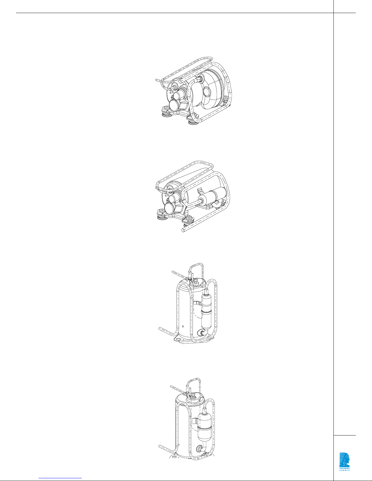
27
Figure 4|Anti-Vibration Piping for HGA
Commercial Refrigeration Compressors
Figure 5|Anti-Vibration Piping for HGA
Air Conditioning Compressors
Figure 6|Anti-Vibration Piping for RGA
Air Conditioning Compressors
Figure 7|Anti-Vibration Piping for RK
Air Conditioning Compressors

www.tecumseh-europe.com
Longueur d’Onde - 07.2004
 Loading...