

Page 1
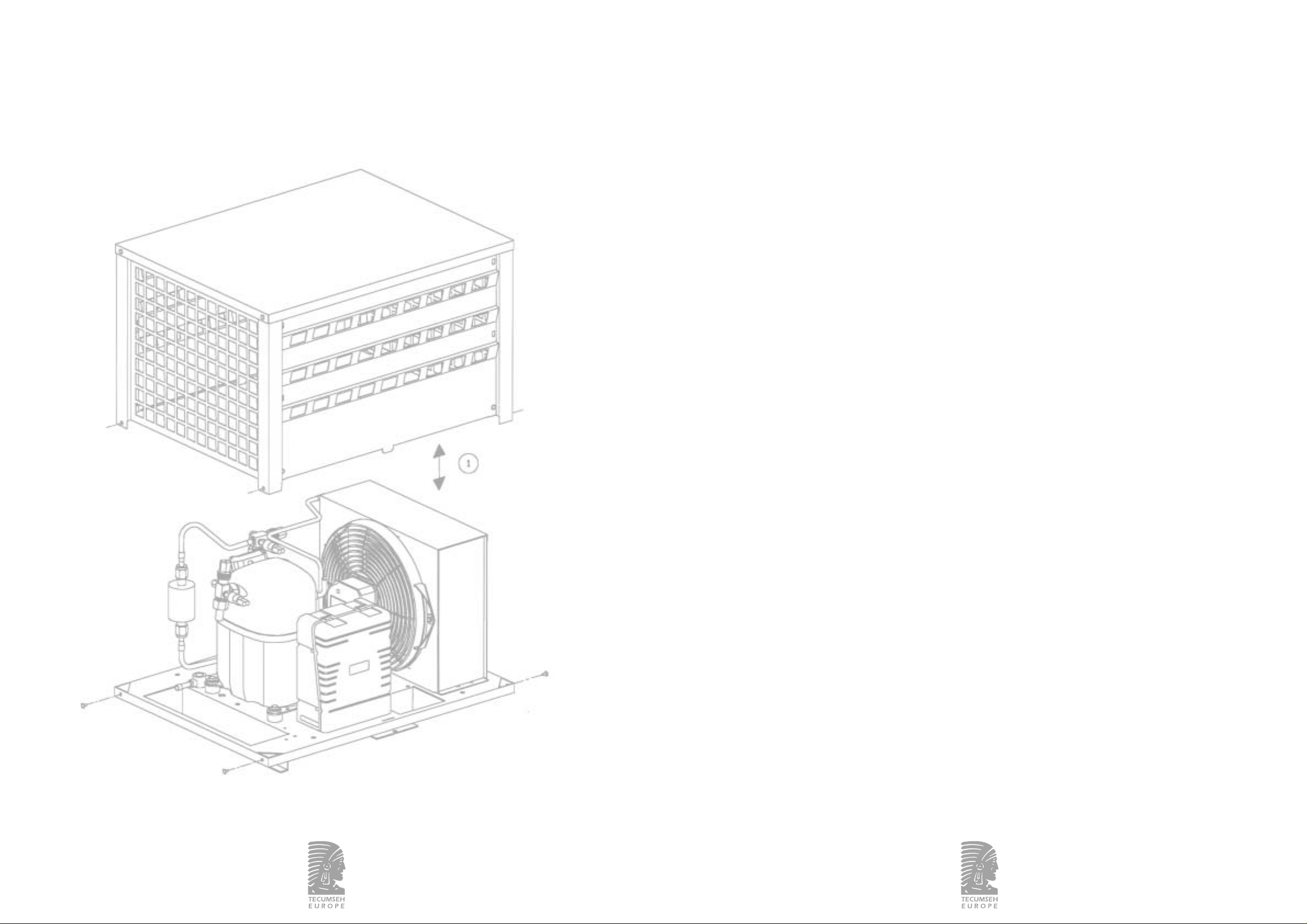
TABLE DES MATIÈRES
1MISE EN GARDE..................................................................................................................................... 6
2 CARACTÉRISTIQUES TECHNIQUES........................................................................................ 6
2.1 Etiquette signalétique................................................................................................................................ 6
2.2 Groupes............................................................................................................................................................ 7
2.2.1 Gamme standard......................................................................................................................................... 7
2.2.2 Gamme HTA.................................................................................................................................................. 8
2.2.3 Dispositif de sécurité................................................................................................................................. 9
2.2.4 Connexions frigorifiques du groupe................................................................................................... 9
2.2.5 Variantes.......................................................................................................................................................... 9
2.2.6 Schémas frigorifiques................................................................................................................................ 9
2.2.7 Schémas électriques................................................................................................................................... 9
3INSTALLATION........................................................................................................................................ 9
3.1 Choix de l'emplacement........................................................................................................................... 9
3.2 Démontage et remontage capotage..................................................................................................... 9
3.3 Raccordements frigorifiques................................................................................................................... 9
3.4 Raccordements électriques................................................................................................................... 10
3.5 Mise en service........................................................................................................................................... 14
4ENTRETIEN - MAINTENANCE..................................................................................................... 14
5GARANTIE................................................................................................................................................. 14
6DÉCLARATION DE CONFORMITÉ........................................................................................... 15
7DÉCLARATION D'INCORPORATION..................................................................................... 15
ANNEXES................................................................................................................................................... 44
2/55
NOTICE POUR GROUPE CARÉNÉ
INSTALLATION INSTRUCTIONS
FOR CONDENSING UNITS WITH CASING
MONTAGEANLEITUNG FÜR
VERFLÜSSIGUNGSSÄTZE
MIT WETTERSCHUTZGEHÄUSE
INSTRUCCIONES PARA GRUPOS
CONDENSADORES CARENADOS
1/55
366304a/10.02 366304a/10.02
Page 2

4/553/55
CONTENTS
1 ADVICE........................................................................................................................................................ 15
2 TECHNICAL DATA ............................................................................................................................... 15
2.1 Label................................................................................................................................................................ 15
2.2 Condensing unit......................................................................................................................................... 16
2.2.1 Standard range........................................................................................................................................... 16
2.2.2 HTA range.................................................................................................................................................... 17
2.2.3 Safety devices.............................................................................................................................................. 18
2.2.4 Refrigeration connections of the unit.............................................................................................. 18
2.2.5 Versions......................................................................................................................................................... 18
2.2.6 Refrigeration circuits............................................................................................................................... 18
2.2.7 Circuit diagrams........................................................................................................................................ 18
3INSTALLATION...................................................................................................................................... 18
3.1 Location......................................................................................................................................................... 18
3.2 Mounting and demounting of the casing........................................................................................ 18
3.3 Refrigeration connections ...................................................................................................................... 18
3.4 Electrical connections............................................................................................................................. 19
3.5 Putting into operation............................................................................................................................. 23
4 SERVICE - MAINTENANCE............................................................................................................ 23
5WARRANTY.............................................................................................................................................. 23
6DECLARATION OF CONFORMITY........................................................................................... 23
7DECLARATION OF INCORPORATION.................................................................................. 23
ANNEXE...................................................................................................................................................... 44
INHALT
1HINWEIS..................................................................................................................................................... 24
2 TECHNISCHE DATEN........................................................................................................................ 24
2.1 Typenschild .................................................................................................................................................. 24
2.2 Verflüssigungssätze................................................................................................................................... 25
2.2.1 Standard-Baureihe.................................................................................................................................... 25
2.2.2 HTA-Baureihe............................................................................................................................................. 26
2.2.3 Sicherheitseinrichtungen........................................................................................................................ 27
2.2.4 Kältetechnische Anschlüsse.................................................................................................................. 27
2.2.5 Varianten....................................................................................................................................................... 27
2.2.6 Kältekreisläufe............................................................................................................................................ 27
2.2.7 Elektrische Schaltbilder.......................................................................................................................... 27
3 MONTAGE ................................................................................................................................................. 27
3.1 Standort......................................................................................................................................................... 27
3.2 Auf-und Abbau des Gehäuses............................................................................................................. 27
3.3 Kältetechnische Anschlüsse.................................................................................................................. 28
3.4 Elektrische Anschlüsse............................................................................................................................ 28
3.5 Inbetriebnahme.......................................................................................................................................... 32
4WARTUNG................................................................................................................................................. 32
5GARANTIE................................................................................................................................................. 33
6 KONFORMITÄTSSERKLÄRUNG................................................................................................ 33
7HERSTELLERERKLÄRUNG ZUM EINBAU......................................................................... 33
ANHANG..................................................................................................................................................... 44
366304a/10.02 366304a/10.02
Page 3

5/55
ÍNDICE
1ADVERTENCIA....................................................................................................................................... 34
2 CARACTERÍSTICAS TÉCNICAS.................................................................................................. 34
2.1 Etiqueta.......................................................................................................................................................... 34
2.2 Grupos............................................................................................................................................................ 35
2.2.1 Gama estándar............................................................................................................................................ 35
2.2.2 Gama HTA................................................................................................................................................... 36
2.2.3 Dispositivo de seguridad........................................................................................................................ 37
2.2.4 Conexiones frigoríficas del grupo...................................................................................................... 37
2.2.5 Variantes........................................................................................................................................................ 37
2.2.6 Esquemas frigoríficos.............................................................................................................................. 37
2.2.7 Esquemas eléctricos................................................................................................................................. 37
3INSTALACIÓN......................................................................................................................................... 37
3.1 Elección del emplazamiento ................................................................................................................. 37
3.2 Desmontaje / Montaje del carenado................................................................................................. 37
3.3 Conexiones frigoríficas........................................................................................................................... 38
3.4 Conexiones eléctricas.............................................................................................................................. 38
3.5 Puesta en servicio ...................................................................................................................................... 42
4MANTENIMIENTO............................................................................................................................... 42
5 GARANTÍA................................................................................................................................................ 43
6DECLARACIÓN DE CONFORMIDAD..................................................................................... 43
7DECLARACIÓN DE INCORPORACIÓN................................................................................. 43
ANEXOS...................................................................................................................................................... 44
366304a/10.02
Page 4
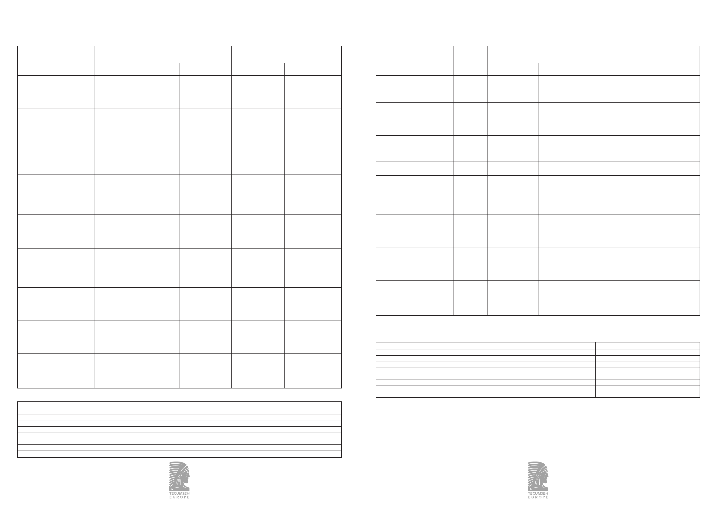
2.2 Groupes
2.2.1 Gamme standard
MHP / R-404A
CAE9450ZMHR CAR 650x500x460 34 3/8 - 9,5 1/4 - 6,3 980 66 30,7 - 25 1,5 - 3
CAE9460ZMHR CAR 650x500x460 34 3/8 - 9,5 1/4 - 6,3 980 66 30,7 - 25 1,5 - 3
CAE9470ZMHR CAR 650x500x460 35 3/8 - 9,5 1/4 - 6,3 1130 69 30,7 - 25 1,5 - 3
CAJ/TAJ9480ZMHR CAR
650x500x460 45 1/2 - 12,7 3/8 - 9,5 1130 69 30,7 - 25 1,5 - 3
CAJ/TAJ9510ZMHR CAR
650x500x460 48 5/8 - 15,8 3/8 - 9,5 980 69 30,7 - 25 1,5 - 3
CAJ/TAJ9513ZMHR CAR
650x500x460 51 5/8 - 15,8 3/8 - 9,5 980 68 30,7 - 25 1,5 - 3
CAJ/TAJ4517ZHR CAR
830x700x570 61 5/8 - 15,8 3/8 - 9,5 2200 75 29,7 - 25,7 2,7 - 4,2
CAJ/TAJ4519ZHR CAR
830x700x570 61 5/8 - 15,8 3/8 - 9,5 2250 75 29,7 - 25,7 2,7 - 4,2
FH/TFH4522ZHR CAR
830x700x570 68 5/8 - 15,8 3/8 - 9,5 2250 75 29,7 - 25,7 2,7 - 4,2
FH/TFH4524ZHR CAR
830x700x570 69 5/8 - 15,8 3/8 - 9,5 2480 76 29,7 - 25,7 2,7 - 4,2
HP / R-134a
CAE4440YHHR CAR 650x500x460 34 3/8 - 9,5 1/4 - 6,3 800 65 18,5 - 13 0,5 - 1,5
CAE4448YHR CAR 650x500x460 34 3/8 - 9,5 1/4 - 6,3 800 64 18,5 - 13 0,5 - 1,5
CAE4456YHR CAR 650x500x460 34 3/8 - 9,5 1/4 - 6,3 980 66 18,5 - 13 0,5 - 1,5
CAJ/TAJ4461YHR CAR
650x500x460 42 1/2 - 12,7 1/4 - 6,3 980 67 18,5 - 13 0,5 - 1,5
CAJ4476YHR CAR 650x500x460 44 1/2 - 12,7 3/8 - 9,5 1130 69 18,5 - 13 0,5 - 1,5
CAJ/TAJ4492YHR CAR
650x500x460 45 1/2 - 12,7 3/8 - 9,5 980 67 18,5 - 13 0,5 - 1,5
CAJ/TAJ4511YHR CAR
650x500x460 46 5/8 - 15,8 3/8 - 9,5 980 68 18,5 - 13 0,5 - 1,5
FH/TFH4518YHR CAR
830x700x570 67 5/8 - 15,8 3/8 - 9,5 2250 75 17 - 13 0,6 - 1,4
FH/TFH4525YHR CAR
830x700x570 69 5/8 - 15,8 3/8 - 9,5 2250 77 17 - 13 0,6 - 1,4
BP / R-404A
CAE2424ZBR CAR 650x500x460 34 3/8 - 9,5 1/4 - 6,3 800 65 30,7 - 25 0,3 - 1,1
CAJ/TAJ2428ZBR CAR
650x500x460 42 1/2 - 12,7 1/4 - 6,3 800 66 30,7 - 25 0,3 - 1,1
CAJ2432ZBR CAR 650x500x460 42 1/2 - 12,7 1/4 - 6,3 800 68 30,7 - 25 0,3 - 1,1
CAJ2440ZBR CAR 650x500x460 44 1/2 - 12,7 3/8 - 9,5 980 68 30,7 - 25 0,3 - 1,1
CAJ/TAJ2446ZBR CAR
650x500x460 46 1/2 - 12,7 3/8 - 9,5 1130 72 30,7 - 25 0,3 - 1,1
CAJ/TAJ2464ZBR CAR
650x500x460 48 5/8 - 15,8 3/8 - 9,5 980 71 30,7 - 25 0,3 - 1,1
FH/TFH2480ZBR CAR
830x700x570 72 5/8 - 15,8 3/8 - 9,5 2200 76 29,7 - 25,7 0,3 - 1,1
FH/TFH2511ZBR CAR
830x700x570 72 5/8 - 15,8 3/8 - 9,5 2250 78 29,7 - 25,7 0,3 - 1,1
7/55
366304a/10.02
Types Dimensions Poids nets Dimensions entrée Débit d'air Puissance Pressostat
groupes groupes sortie (ø) frigorifique condenseur acoustique
[mm] [kg] [m
3
/h] [dBA]
Aspiration
[in – mm]
Ligne liquide
[in - mm]
BP [bar]
HP [bar]
Types Dimensions Poids nets Dimensions entrée Débit d'air Puissance Pressostat
groupes groupes sortie (ø) frigorifique condenseur acoustique
[mm] [kg] [m3/h] [dBA]
Aspiration
[in – mm]
Ligne liquide
[in - mm]
BP [bar]
HP [bar]
Types Dimensions Poids nets Dimensions entrée Débit d'air Puissance Pressostat
groupes groupes sortie (ø) frigorifique condenseur acoustique
[mm] [kg] [m3/h] [dBA]
Aspiration
[in – mm]
Ligne liquide
[in - mm]
BP [bar]
HP [bar]
366304a/10.02
Cette notice concerne les groupes carénés dont les
caractéristiques sont décrites dans le paragraphe 2.
Lire attentivement cette notice avant de commencer
le montage du groupe.
1 - MISE EN GARDE
TRANSPORT
Pour toute information relative à la livraison des groupes,
se référer à vos conditions de vente.
INSTALLATION
- L'installation de ce groupe et du matériel s’y rapportant
doit être effectuée par un personnel qualifié.
- Respecter les normes en vigueur dans le pays où le groupe
est installé et les règles de l'art pour les connexions
frigorifiques et électriques.
- La responsabilité de TECUMSEH EUROPE S.A. ne pourra
être retenue si le montage et la maintenance ne sont
pas conformes aux indications fournies dans cette notice.
2 - CARACTÉRISTIQUES TECHNIQUES
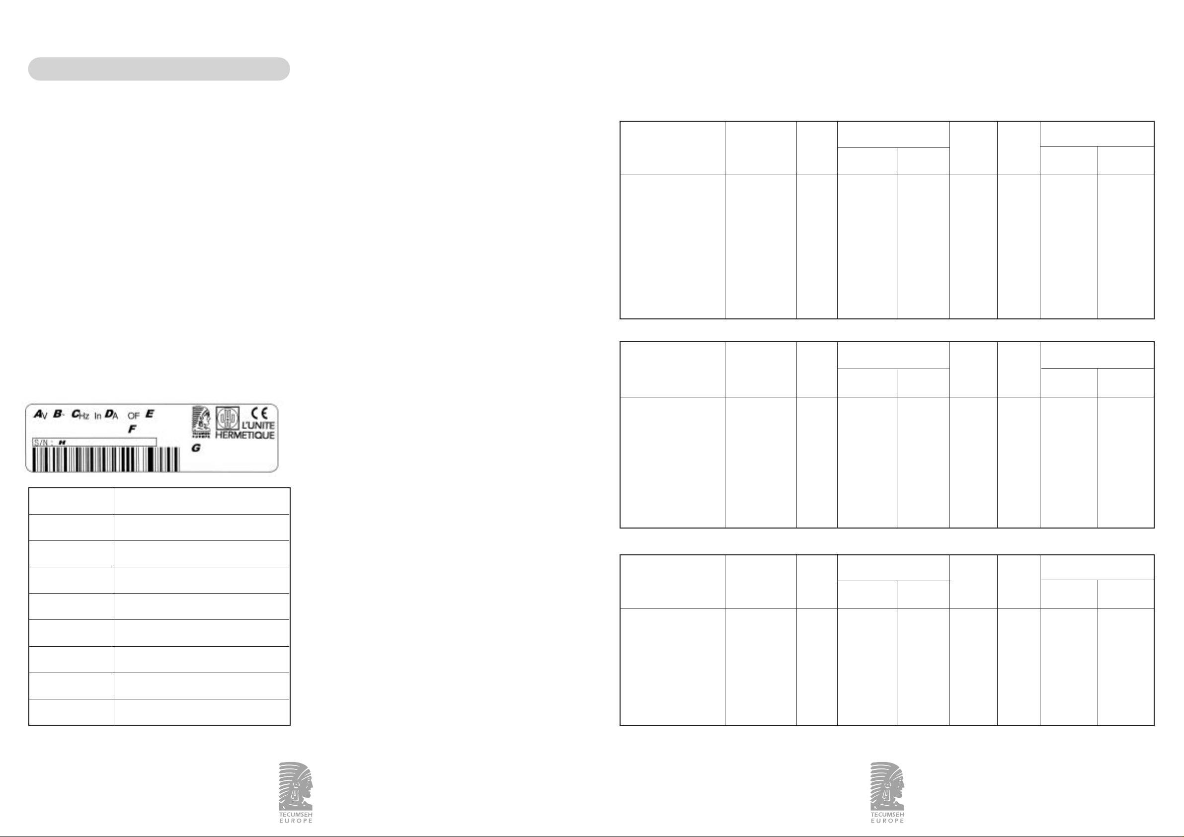
2.1 Etiquette signalétique
RÉFÉRENCES DÉSIGNATIONS
ATension nominale
BNombre de phases
C Fréquence nominale
DIntensité nominale
ENuméro d'ordre de fabrication
FFluide frigorigène
GDésignation du groupe
H
Date de fabrication et
numéro de nomenclature
6/55
Français
Page 5
2.2.3 Dispositif de sécurité
2.2.4 Connexions frigorifiques du groupe
GROUPES ASPIRATION DÉPART LIQUIDE
CAE Kit de raccordement Voyant liquide
CAJ / TAJ Kit de raccordement Voyant liquide
FH / TFH Vanne à braser Voyant liquide
Kit de raccordement : son rôle est d'assurer l'étanchéité de la
liaison entre le groupe et le circuit frigorifique,
d'augmenter la fiabilité du raccordement dans le temps et de
faciliter la maintenance du groupe. La partie à braser est en
cuivre. L'étanchéité est assurée par une coupelle de cuivre
qu'il est conseillé de changer après chaque démontage. Le kit
de raccordement est livré monté et étanche. Il n’est pas
nécessaire de le retirer pour le braser.
2.2.5 Variantes
Les groupes existent dans les versions suivantes :
bouteille avec bouchon fusible - pressostat HP à réarmement
manuel - résistance de carter (suivant modèles) - boîtier électrique avec sectionneur - bouteille anti-coup de liquide
pour les groupes de dimension 830x700x570.
2.2.6 Schémas frigorifiques
Voir Annexe 1.
2.2.7 Schémas électriques
Voir Annexe 2.
3 - INSTALLATION
DÉBALLAGE
Vérifier le bon aspect extérieur.
Vérifier l’absence de choc ou déformation.
MANUTENTION
Attention : ne pas manipuler le groupe par son carénage
mais par son socle qui est prévu à cet effet.
3.1 Choix de l'emplacement
Le groupe ne devra pas bloquer ou gêner un passage, le
déplacement des personnes, l’ouverture de portes ou
de volets…
La surface supportant le groupe doit être suffisamment
solide (mur ou sol). Se référer au tableau §2.2 pour les poids
des groupes.
Respecter les distances entre le groupe et les obstacles
l’entourant afin d’assurer un bonne circulation de l’air.
Voir schéma Annexe 3.
Dans le cas d’un emplacement contre un mur,
TECUMSEH EUROPE S.A. conseille de positionner le flanc
" côté bouteille " face au mur pour garder le maximum d’accessibilité aux composants.
Voir schéma Annexe 3.
MONTAGE AU SOL
Vérifier que le groupe est de niveau. Fixer le groupe
en 4 points.
Voir Annexe 4 pour les dimensions des points de fixation.
MONTAGE MURAL
Les équerres supports ne sont pas fournies. Utiliser des
équerres supports disponibles chez votre distributeur.
Vérifier que le groupe est de niveau. Fixer le groupe
en 4 points.
Voir Annexe 4 pour les dimensions des points de fixation.
3.2 Démontage / remontage capotage
Rapide :
un démontage rapide du carénage s'effectue en dévissant les
4 vis situées sur le socle. Voir Annexe 5 – Schéma 1.
Partiel :
un démontage partiel du carénage s'effectue en dévissant les
4 vis situées sur les flancs. Voir Annexe 5 – Schéma 2.
Complet :
un démontage complet du carénage s'effectue en dévissant
les 12 vis. Voir Annexe 5 – Schéma 3.
3.3 Raccordements frigorifiques
Afin d'assurer toujours le meilleur niveau de qualité de nos
produits, le circuit frigorifique du groupe a été déshydraté.
Il est livré sous pression d'azote.
RAPPELS
Pour préserver la qualité du groupe TECUMSEH EUROPE
S.A. et assurer son bon fonctionnement, il est conseillé de :
- réaliser les brasures sous azote sec,
- calorifuger la canalisation d'aspiration jusqu'à l’entrée du
compresseur. Le matériel utilisé devra être anti-condensation.
PASSAGE DES TUYAUTERIES
L’arrivée des tuyauteries dans le groupe se fait par le
dessous du socle. Voir schéma Annexe 6.
9/55
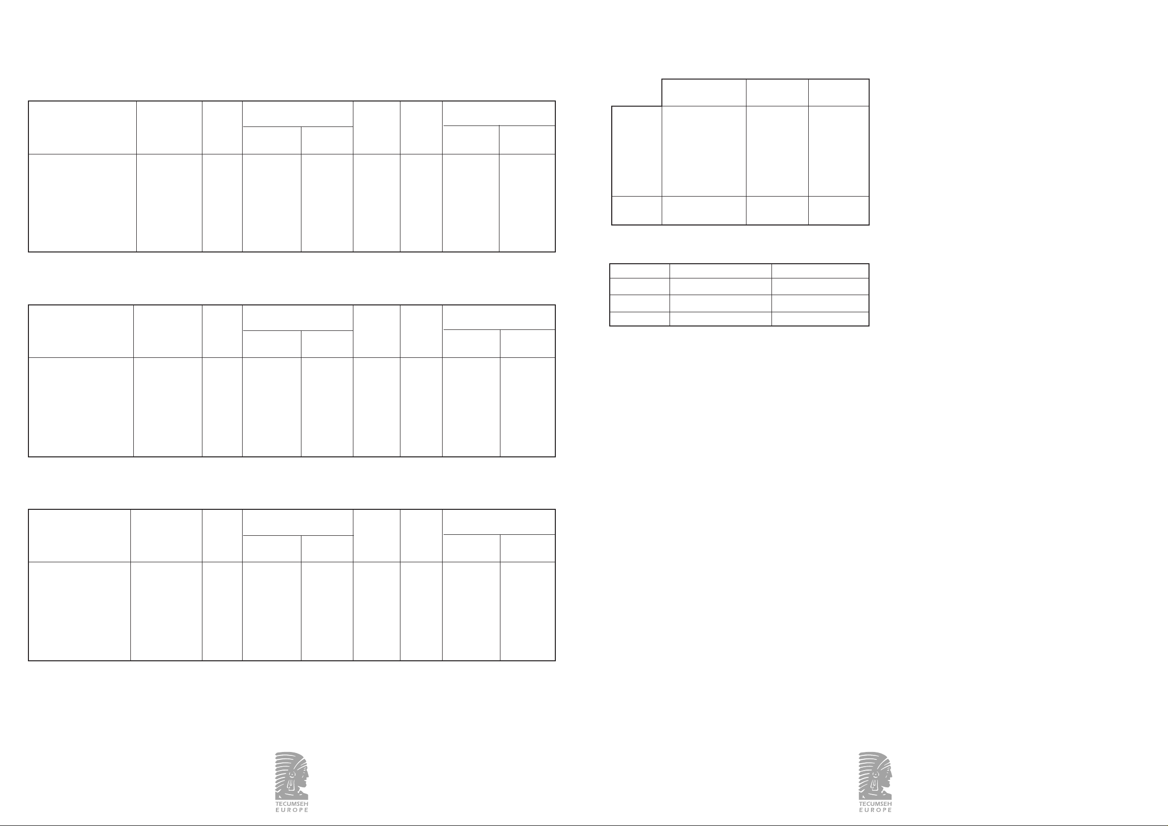
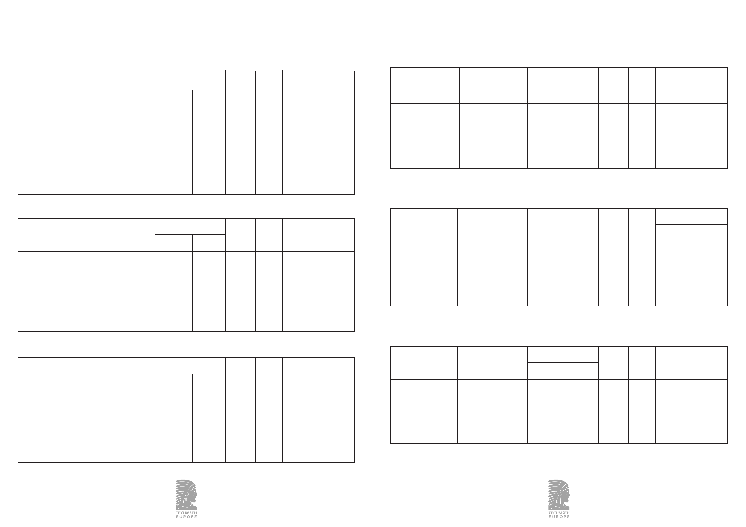
2.2.2 Gamme HTA
MHP / R-404A
CAET9450ZMHR CAR 650x500x460 35 3/8 - 9,5 1/4 - 6,3 1130 68 30,7 - 25 1,5 - 3
CAET9460ZMHR CAR 650x500x460 35 3/8 - 9,5 1/4 - 6,3 1130 68 30,7 - 25 1,5 - 3
CAET9470ZMHR CAR 650x500x460 36 3/8 - 9,5 1/4 - 6,3 980 67 30,7 - 25 1,5 - 3
CAJ/TAJT9480ZMHR CAR
650x500x460 47 1/2 - 12,7 3/8 - 9,5 980 66 30,7 - 25 1,5 - 3
CAJ/TAJT9510ZMHR CAR
830x700x570 52 5/8 - 15,8 3/8 - 9,5 1180 69 29,7 - 25,7 1,5 - 3
CAJ/TAJT9513ZMHR CAR
830x700x570 57 5/8 - 15,8 3/8 - 9,5 2250 74 29,7 - 25,7 1,5 - 3
CAJ/TAJT4517ZHR CAR
830x700x570 61 5/8 - 15,8 3/8 - 9,5 2250 75 29,7 - 25,7 2,7 - 4,2
HP / R-134a
CAET4440YHR CAR 650x500x460 34 3/8 - 9,5 1/4 - 6,3 980 66 18,5 - 13 0,5 - 1,5
CAET4448YHR CAR 650x500x460 35 3/8 - 9,5 1/4 - 6,3 1130 68 18,5 - 13 0,5 - 1,5
CAET4456YHR CAR 650x500x460 35 3/8 - 9,5 1/4 - 6,3 1130 68 18,5 - 13 0,5 - 1,5
CAJ/TAJT4461YHR CAR
650x500x460 44 1/2 - 12,7 1/4 - 6,3 980 68 18,5 - 13 0,5 - 1,5
CAJT4476YHR CAR 650x500x460 45 1/2 - 12,7 3/8 - 9,5 980 66 18,5 - 13 0,5 - 1,5
CAJ/TAJT4492YHR CAR
830x700x570 51 1/2 - 12,7 3/8 - 9,5 2200 74 17 - 13 0,6 - 1,4
CAJ/TAJT4511YHR CAR
830x700x570 52 5/8 - 15,8 3/8 - 9,5 2250 74 17 - 13 0,6 - 1,4
BP / R-404A
CAET2424ZBR CAR 650x500x460 35 3/8 - 9,5 1/4 - 6,3 1130 68 30,7 - 25 0,3 - 1,1
CAJ/TAJT2428ZBR CAR
650x500x460 43 1/2 - 12,7 1/4 - 6,3 1130 69 30,7 - 25 0,3 - 1,1
CAJT2432ZBR CAR 650x500x460 43 1/2 - 12,7 1/4 - 6,3 1130 70 30,7 - 25 0,3 - 1,1
CAJT2440ZBR CAR 650x500x460 44 1/2 - 12,7 3/8 - 9,5 980 71 30,7 - 25 0,3 - 1,1
CAJ/TAJT2446ZBR CAR
650x500x460 47 1/2 - 12,7 3/8 - 9,5 980 71 30,7 - 25 0,3 - 1,1
CAJ/TAJT2464ZBR CAR
830x700x570 54 5/8 - 15,8 3/8 - 9,5 2250 71 29,7- 25,7 0,3 - 1,1
FH/TFHT2480ZBR CAR
830x700x570 72 5/8 - 15,8 3/8 - 9,5 2250 76 29,7- 25,7 0,3 - 1,1
8/55
GROUPES HP - MHP GROUPES BP POUVOIR
DE COUPURE
Petit carénage Mini pressostat HP Mini pressostat HP 12 A
(650 x 500 x 460) et BP à valeur fixe
à valeur fixe non réglable non réglable
Pressostat BP 16 A
réglable
Moyen carénage Pressostat HP/BP Pressostat HP/BP 16 A
(830x700x570) réglable réglable
Types Dimensions Poids nets Dimensions entrée Débit d'air Puissance Pressostat
groupes groupes sortie (ø) frigorifique condenseur acoustique
[mm] [kg] [m
3
/h] [dBA]
Aspiration
[in – mm]
Ligne liquide
[in - mm]
BP [bar]
HP [bar]
Types Dimensions Poids nets Dimensions entrée Débit d'air Puissance Pressostat
groupes groupes sortie (ø) frigorifique condenseur acoustique
[mm] [kg] [m
3
/h] [dBA]
Aspiration
[in – mm]
Ligne liquide
[in - mm]
BP [bar]
HP [bar]
Types Dimensions Poids nets Dimensions entrée Débit d'air Puissance Pressostat
groupes groupes sortie (ø) frigorifique condenseur acoustique
[mm] [kg] [m3/h] [dBA]
Aspiration
[in – mm]
Ligne liquide
[in - mm]
BP [bar]
HP [bar]
366304a/10.02 366304a/10.02
Page 6
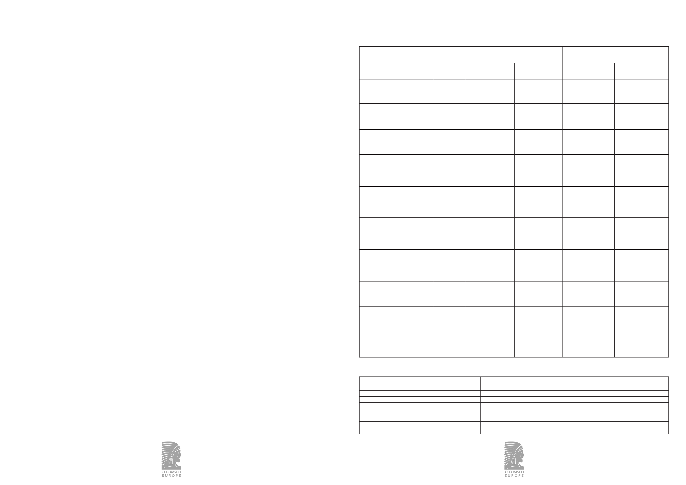
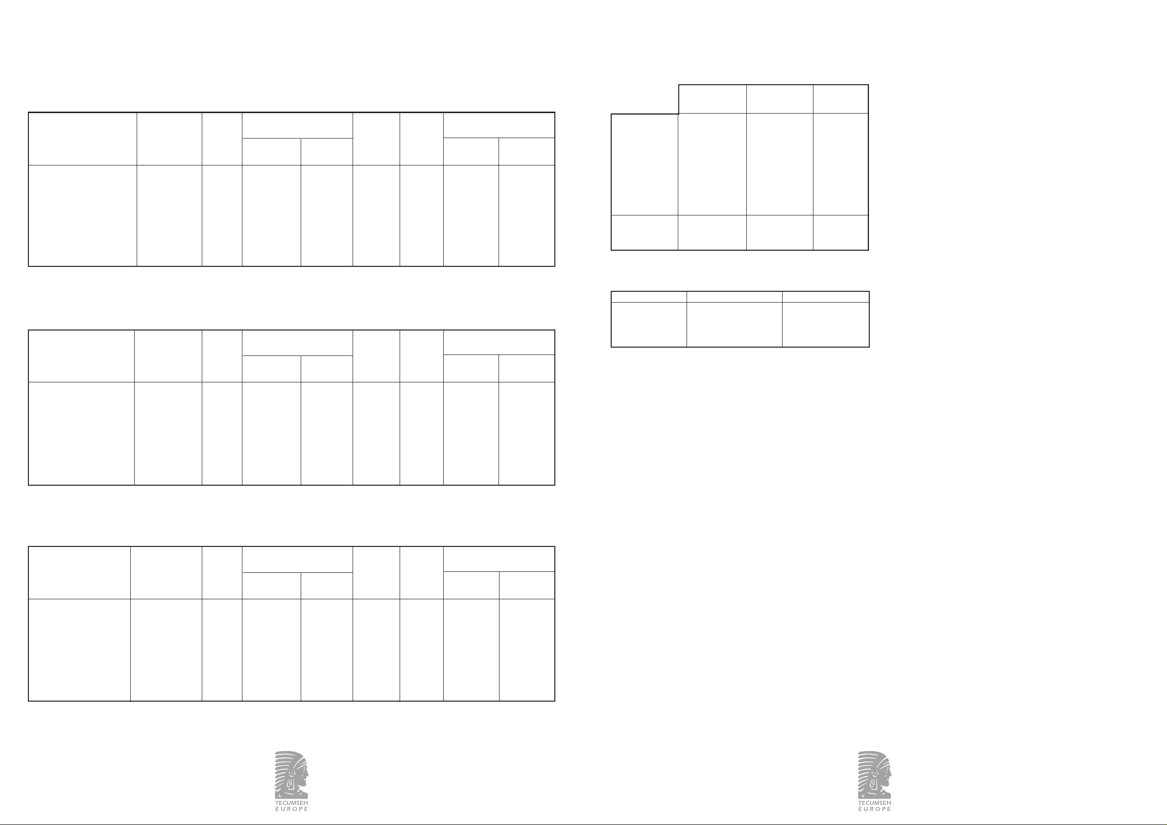
Gamme MHP / R-404A
Intensité de fonctionnement Intensité de fonctionnement
Type Tension
maximale version STANDARD maximale version HTA
Compresseur Ventilateur Compresseur Ventilateur
(A) (A) (A) (A)
A8.8 / 9.31.3 / 1.3 8.8 / 9.3 1.3 / 1.3
CAE9450ZMHR CAR F 3.9 0.5 3.9 0.5
CAET9450ZMHR CAR G 3.9 0.5 3.9 0.5
H4.9 0.7 4.9 0.7
A12 / 12 1.3 / 1.3 12 / 12 1.3 / 1.3
CAE9460ZMHR CAR F 4.1 0.5 4.1 0.5
CAET9460ZMHR CAR G 5 0.5 5 0.5
H5.7 0.7 5.7 0.7
A 16.2 / 16.4 1.3 / 1.3 16.2 / 16.4 1.3 / 1.3
CAE9470ZMHR CAR F 5.6 0.5 5.6 0.5
CAET9470ZMHR CAR G 6 0.5 6 0.5
H7 0.7 7 0.7
A 14.6 / 17.3 1.3 / 1.3 14.6 / 17.3 1.3 / 1.3
F6.6 0.5 6.6 0.5
CAJ/TAJ9480ZMHR CAR G 6.5 0.5 6.5 0.5
CAJ/TAJT9480ZMHR CAR H 8.5 0.7 8.5 0.7
T2.2 / 2.20.3 / 0.3 2.2 / 2.2 0.3 / 0.3
A 19 / 21.4 1.3 / 1.3 / /
CAJ/TAJ9510ZMHR CAR F 7.1 0.5 7.1 0.6 / 0.6
CAJ/TAJT9510ZMHR CAR G 7.7 0.5 / /
H13 0.7 / /
T3 / 30.3 / 0.3 3 / 3 0.4 / 0.4
A 22.2 / 22.4 1.3 / 1.3 22.2 / 22.4 1.5 / 1.8
CAJ/TAJ9513ZMHR CAR F 10.1 0.5 10.1 0.8
CAJ/TAJT9513ZMHR CAR G 9.9 0.5 9.9 0.8
H 12.8 0.7 12.8 1.4
T3.9 / 4.10.3 / 0.3 3.9 / 4.1 0.6 / 0.6
F 10.6 0.8 10.6 0.8
CAJ/TAJ4517ZHR CAR G 11 0.8 11 0.8
CAJ/TAJT4517ZHR CAR H 14 1.4 14 1.4
K6 / 6.8 0.8 / 1.4 6 / 6.8 0.8 / 1.4
T4 / 40.4 / 0.6 4 / 4 0.4 / 0.6
F 15.4 0.8 / /
CAJ/TAJ4519ZHR CAR G 15.5 0.8 / /
H17 1.4 / /
T4.8 / 4.70.4 / 0.6 / /
F16 0.8 / /
FH/TFH4522ZHR CAR K 8.8 / 11.2 0.8 / 1.4 / /
T6.3 / 6.50.4 / 0.6 / /
F 18.1 0.8 / /
G 17.6 0.8 / /
FH/TFH4524ZHR CAR H 23 1.4 / /
K10 / 13 0.8 / 1.4 / /
T6.3 / 6.60.4 / 0.6 / /
CODES TENSIONS
CODES TENSIONS MONOPHASÉE TRIPHASÉE
A 100/115V – 50/60Hz /
C 208/230V – 50/60Hz /
F 220/240V – 50Hz /
G 208/220V – 50Hz /
H 208/220V – 60Hz /
K / 220V – 50/60Hz
Q / 200V – 50/60Hz
T / 400/440V – 50/60Hz
11/55
RACCORDEMENT À L’ASPIRATION
Gamme CAE – CAJ/T AJ : la vanne est montée étanche sur les
compresseurs de la gamme CAJ/TAJ. Braser le tube sur le kit
de raccordement, monté étanche, en cuivre. Il n’est pas
nécessaire de le retirer pour le braser.
Gamme FH/TFH : la vanne est montée étanche sur le
compresseur. Braser directement sur celle-ci (vanne acier).
RACCORDEMENT AU DÉPART LIQUIDE
Recouvrir le voyant liquide d’un chiffon mouillé avant de le
braser (raccord en cuivre).
3.4 Raccordements électriques
RAPPELS
Pour préserver la qualité du groupe TECUMSEH EUROPE
S.A., la sécurité de l’installation et assurer son bon fonctionnement, il est impératif de :
- câbler toujours le groupe hors tension.
- Valider la compatibilité de la tension d’alimentation de
l’installation avec celle du groupe (voir plaque signalétique).
- Valider la compatibilité du schéma électrique du groupe
avec celle de l'installation.
- Dimensionner les câbles de raccordement (puissance, commande) en fonction des caractéristiques du groupe installé
(voir tableau des intensités ci-après).
- La ligne d'alimentation électrique devra être protégée et
comporter une ligne de mise à la terre.
- Effectuer les raccordements électriques conformément aux
normes du pays.
PASSAGE DES CÂBLES
L’arrivée des câbles dans le groupe se fait par le dessous du
socle.
Voir schéma Annexe 6.
RACCORDEMENT DES COMPOSANTS
● Se référer au schéma électrique (voir Annexe 2) pour
raccorder les composants.
● Raccorder tous les appareils de régulation et de sécurité
montés sur la machine.
● Fermer le boîtier électrique après câblage (couvercle vissé).
10/55
366304a/10.02 366304a/10.02
Page 7
13/55
Gamme HP / R-134a
Intensité de fonctionnement Intensité de fonctionnement
maximale version STANDARD maximale version HTA
Compresseur (A) Ventilateur (A) Compresseur (A) Ventilateur (A)
A 10 / 10 1.3 / 1.3 10 / 10 1.3 / 1.3
CAE4440YHHR CAR C 4.7 / 4.6 0.5 / 0.5 4.7 / 4.6 0.5 / 0.5
CAET4440YHHR CAR F 4 0.5 4 0.5
G4 0.5 4 0.5
H4.7 0.7 4.7 0.7
A9.7 / 10.2 1.3 / 1.3 9.7 / 10.2 1.3 / 1.3
CAE4448YHR CAR C 4.4 / 5.2 0.5 / 0.5 4.4 / 5.2 0.5 / 0.5
CAET4448YHR CAR F 4.6 0.5 4.6 0.5
G4.4 0.5 4.4 0.5
H5.7 0.7 5.7 0.7
A 13 / 13.2 1.3 / 1.3 13 / 13.2 1.3 / 1.3
CAE4456YHR CAR C 5.5 / 6.7 0.5 / 0.5 5.5 / 6.7 0.5 / 0.5
CAET4456YHR CAR F 5 0.5 5 0.5
G5.5 0.5 5.5 0.5
H7.5 0.7 7.5 0.7
A 13.8 / 13.8 1.3 / 1.3 13.8 / 13.8 1.3 / 1.3
C5.7 / 6.80.5 / 0.5 5.7 / 6.8 0.5 / 0.5
CAJ/TAJ4461YHR CAR F 5.9 0.5 5.9 0.5
CAJ/TAJT4461YHR CAR G 5.3 0.5 5.3 0.5
H8.2 0.7 8.2 0.7
T1.5 / 1.50.3 / 0.3 1.5 / 1.5 0.3 / 0.3
A 14.2 / 15.2 1.3 / 1.3 14.2 / 15.2 1.3 / 1.3
CAJ4476YHR CAR C 6.5 / 7.6 0.5 / 0.5 6.5 / 7.6 0.5 / 0.5
CAJT4476YHR CAR F 7.2 0.5 7.2 0.5
G6.5 0.5 6.5 0.5
H8.6 0.7 8.6 0.7
A 17 / 18 1.3 / 1.3 17 / 18 1.5 / 1.8
C7.8 / 8.90.5 / 0.5 / /
CAJ/TAJ4492YHR CAR F 8.2 0.5 8.2 0.8
CAJ/TAJT4492YHR CAR G 8.4 0.5 8.4 0.8
H 10.2 0.7 10.2 1.4
T2.8 / 2.80.3 / 0.3 2.8 / 2.8 0.4 / 0.6
C8.3 / 8.80.5 / 0.5 / /
CAJ/TAJ4511YHR CAR F 8.5 0.5 8.5 0.8
CAJ/TAJT4511YHR CAR G 8.5 0.5 8.5 0.8
H 10.3 0.7 10.3 1.4
T3.4 / 3.40.3 / 0.3 3.4 / 3.4 0.4 / 0.6
F 11.2 0.8 / /
G 12.1 0.8 / /
FH/TFH4518YHR CAR H 16.6 1.4 / /
K7 / 100.8 / 1.4 / /
T4.2 / 4.60.4 / 0.6 / /
F 15.2 0.8 / /
G 16.1 0.8 / /
FH/TFH4525YHR CAR H 20.3 1.4 / /
K 12 / 12.3 0.8 / 1.4 / /
T5.6 / 5.50.4 / 0.6 / /
CODES TENSIONS
CODES TENSIONS MONOPHASÉE TRIPHASÉE
A 100/115V – 50/60Hz /
C 208/230V – 50/60Hz /
F 220/240V – 50Hz /
G 208/220V – 50Hz /
H 208/220V – 60Hz /
K/220V – 50/60Hz
Q/200V – 50/60Hz
T/400/440V – 50/60Hz
12/55
366304a/10.02 366304a/10.02
Gamme BP / R-404A
Intensité de fonctionnement Intensité de fonctionnement
maximale version STANDARD maximale version HTA
Compresseur (A) Ventilateur (A) Compresseur (A) Ventilateur (A)
A 12.2 / 12.3 1.3 / 1.3 12.2 / 12.3 1.3 / 1.3
CAE2424ZBR CAR F 4.7 0.5 4.7 0.5
CAET2424ZBR CAR G 4.8 0.5 4.8 0.5
H5.5 0.7 5.5 0.7
A 11.9 / 12.2 1.3 / 1.3 11.9 / 12.2 1.3 / 1.3
CAJ/TAJ2428ZBR CAR F 5.1 0.5 5.1 0.5
CAJ/TAJT2428ZBR CAR G 6 0.5 6 0.5
H7.3 0.7 7.3 0.7
T1.5 / 1.50.3 / 0.3 1.5 / 1.5 0.3 / 0.3
A 12.3 / 13.7 1.3 / 1.3 14 / 14 1.3 / 1.3
CAJ2432ZBR CAR F 6.3 0.5 4.4 0.5
CAJT2432ZBR CAR G 5.2 0.5 6.7 0.5
H6.4 0.7 6.8 0.7
CAJ2440ZBR CAR
F2.9 / 6.5 0.5 2.9 / 6.5 0.5
CAJT2440ZBR CAR
A 19.4 / 19.4 1.3 / 1.3 19.4 / 19.4 1.3 / 1.3
F7.5 0.5 7.5 0.5
CAJ/TAJ2446ZBR CAR G 8.3 0.5 8.3 0.5
CAJ/TAJT2446ZBR CAR H 10 0.7 10 0.7
Q5.7 / 5.50.5 / 0.5 5.7 / 5.5 0.5 / 0.5
T2.8 / 30.3 / 0.3 2.8 / 3 0.3 / 0.3
A 23 / 23.4 1.3 / 1.3 23 / 23.4 1.5 / 1.8
CAJ/TAJ2464ZBR CAR F 9.7 0.5 9.7 0.8
CAJ/TAJT2464ZBR CAR G 13 0.5 13 0.8
H14 0.7 14 1.4
T3.7 / 3.70.3 / 0.3 3.7 / 3.7 0.4 / 0.6
F 19.2 0.8 19.2 0.8
FH/TFH2480ZBR CAR G 19 0.8 19 0.8
FH/TFHT2480ZBR CAR H 24 1.4 24 1.4
K 10.6 / 10.8 0.8 / 1.4 10.6 / 10.8 0.8 / 1.4
T3.9 / 3.90.4 / 0.63.9 / 3.90.4 / 06
F24 0.8 / /
G25 0.8 / /
FH/TFH2511ZBR CAR H 28 1.4 / /
K 13.3 / 13.4 0.8 / 1.4 / /
T5 / 5.20.4 / 0.6 / /
CODES TENSIONS
CODES TENSIONS MONOPHASÉE TRIPHASÉE
A 100/115V – 50/60Hz /
C 208/230V – 50/60Hz /
F 220/240V – 50Hz /
G 208/220V – 50Hz /
H 208/220V – 60Hz /
K/220V – 50/60Hz
Q/200V – 50/60Hz
T/400/440V – 50/60Hz
Type Tension
Type Tension
Page 8

14/55
6 - DÉCLARATION DE CONFORMITÉ
Les groupes de condensation sont conformes à la Directive
Basse Tension 93/68/CE .
Les tubes intégrés aux modèles sont conformes à la Directive
des Equipements Sous Pression 97/23/CE du 29 mai 1997,
clause 3 § 3. (Voir doc . CIRC n° 463). Nos groupes de
condensation ne sont pas directement concernés par la DESP
mais doivent être considérés comme un sous-ensemble compatible.
7 - DÉCLARATION D'INCORPORATION
Toute intervention sur ce groupe doit être exécutée exclusivement par du personnel professionnel autorisé.
Ce produit est un composant défini pour être incorporé à une
machine au sens de la directive européenne 89/392/CE.
Il n’est pas admis de le mettre en fonctionnement avant que
la machine dans laquelle il est incorporé soit trouvée ou
déclarée conforme à la législation en vigueur. A ce titre, ce
produit n’est pas lui-même soumis à la directive 89/392/CE.
Afin de pouvoir améliorer en permanence ces produits,
TECUMSEH EUROPE S.A. se réserve le droit de modifier
cette notice sans préavis.
These instructions concern condensing units as described in
Chapter 2. Read carefully the following instructions before
installing the unit.
1 - ADVICE
TRANSPORT
For information regarding the supply of these units refer to
your terms and conditions.
INSTALLATION
- This condensing unit and relating equipment must be installed by qualified staff.
- The installation of the unit is subjected to the norms and
technical standards for refrigerating and electrical connections in the respective country.
- TECUMSEH EUROPE S.A. declines all responsibility if
installation and maintenance are not carried out according to
these instructions.
2 - TECHNICAL DATA
2.1 Label
REFERENCE DESCRIPTION
ANominal voltage
BNumber of phases
CNominal frequency
DNominal current
EProduction order number
FRefrigerant
GDescription of the unit
HManufacturing date and number
15/55
3.5 Mise en service
ÉTANCHÉITÉ DU CIRCUIT
Une recherche systématique des fuites, sur tous les raccords
effectués, doit être faite à l’aide d’un détecteur électronique
de fuite.
TIRAGE AU VIDE
Tirer au vide l'installation pour atteindre une pression résiduelle d'environ 200 micromètres de mercure, garantissant
une bonne qualité du vide.
Il est conseillé de tirer au vide en simultané sur les circuits
HP et BP. Cela permettra de diminuer le temps de cette opération et d'assurer un niveau de vide identique dans la
totalité du circuit.
CHARGE EN FLUIDE FRIGORIGÈNE
Charger l'installation uniquement avec le fluide frigorigène
pour lequel le groupe a été conçu (voir plaque signalétique).
La charge en fluide frigorigène se fera toujours en phase
liquide afin de garder la bonne proportion du mélange.
Ne jamais démarrer le compresseur si le vide n’est pas cassé
en HP et BP. Pour cela, il est conseillé de charger lentement
le circuit frigorifique de 4 à 5 bars s’il est au R-404A, et environ 2 bars si il est au R-134a.
Le complément de la charge se fera jusqu'à l'obtention du
régime de fonctionnement nominal de l'installation.
Consulter le paragraphe "Vérification avant démarrage"
avant la mise sous tension.
VÉRIFICATION AVANT DÉMARRAGE
1. Compatibilité de la tension d'alimentation avec celle du
groupe,
2. calibrage des organes de protection électriques,
3. couverture totale des vannes de service,
4. fonctionnement de la résistance de carter ou de la ceinture
chauffante,
5. libre rotation de l'hélice du ventilateur condenseur,
6. inspection de l'installation pour relever d’éventuelles
anomalies.
VÉRIFICATION APRÈS DÉMARRAGE
Après quelques heures de fonctionnement, faire les vérifications ci-dessous :
1. tension et intensité absorbée par le groupe,
2. pressions de l’installation HP et BP,
3. rotation du ventilateur condenseur,
4. surchauffe,
5. refaire une recherche des fuites.
S’assurer du bon fonctionnement global de l'installation.
Faire une inspection générale de l'installation (propreté de
l'installation, bruits anormaux …).
Remonter le carénage et le fixer . Vérifier l'absence de vibrations.
4 - ENTRETIEN – MAINTENANCE
Nettoyage de l'échangeur et du groupe une fois par an
minimum.
Recherche des fuites une fois par an ou en fonction des réglementations locales.
Vérifier régulièrement :
- les organes de sécurité et de régulation,
- les états des connexions électriques et frigorifiques
(resserrage, oxydation …),
- les conditions de fonctionnement,
- les fixations du groupe sur son support,
- les fixations du carénage pour qu'il ne vibre pas,
- le fonctionnement de la résistance de carter ou de la
ceinture chauffante.
Mini pressostats :
les pressostats à valeur fixe ont un couple de serrage compris
entre 13 Nm et 16 Nm (132 cm.kg à 163 cm.kg). La conception du raccord rend inutile l'utilisation de joint en cuivre
(coupelle) pour assurer l'étanchéité.
Pressostats réglables :
les raccords souples, dont sont pourvus les pressostats réglables, ont un couple de serrage compris entre 10 Nm et 12 Nm
(102 cm.kg et 122 cm.kg). L'étanchéité est assurée par une
coupelle de cuivre qu'il est conseillé de changer après chaque
démontage du raccord souple.
Déshydrateur :
les groupes carénés sont équipés d'un déshydrateur à visser
connecté à des kits de raccordement.
L'étanchéité est assurée par une coupelle de cuivre qu'il est
conseillé de changer après chaque démontage.
Couple de vissage des kits de raccordement :
Kit de raccordement Couple de vissage maxi
[Nm – cm.kg]
ø 1/4" 20 - 203
ø 3/8" 30 - 305
Choix du déshydrateur :
dans le cas du changement du déshydrateur, le remplacer par
un déshydrateur de capacité équivalente.
5 - GARANTIE
Pour toute information sur la garantie du groupe, se référer
à vos conditions de vente.
English
366304a/10.02 366304a/10.02
Page 9
16/55
Type Dimensions Net weight Refrigeration connections Air flow rate Sound Pressure switch
Units Units diameter (ø) condensor
power level
[mm] [kg] [m3/h] [dBA]
Suction line
[in – mm]
Liquid line
[in - mm]
LBP [bar]
HBP [bar]
Type Dimensions Net weight Refrigeration connections Air flow rate Sound Pressure switch
Units Units diameter (ø) condensor
power level
[mm] [kg] [m3/h] [dBA]
Suction line
[in – mm]
Liquid line
[in - mm]
LBP [bar]
HBP [bar]
17/55
2.2 Condensing units
2.2.1 Standard range
MHBP / R-404A
CAE9450ZMHR CAR 650x500x460 34 3/8 - 9.5 1/4 - 6.3 980 66 30.7 - 25 1.5 - 3
CAE9460ZMHR CAR 650x500x460 34 3/8 - 9.5 1/4 - 6.3 980 66 30.7 - 25 1.5 - 3
CAE9470ZMHR CAR 650x500x460 35 3/8 - 9.5 1/4 - 6.3 1130 69 30.7 - 25 1.5 - 3
CAJ/TAJ9480ZMHR CAR
650x500x460 45 1/2 - 12.7 3/8 - 9.5 1130 69 30.7 - 25 1.5 - 3
CAJ/TAJ9510ZMHR CAR
650x500x460 48 5/8 - 15.8 3/8 - 9.5 980 69 30.7 - 25 1.5 - 3
CAJ/TAJ9513ZMHR CAR
650x500x460 51 5/8 - 15.8 3/8 - 9.5 980 68 30.7 - 25 1.5 - 3
CAJ/TAJ4517ZHR CAR
830x700x570 61 5/8 - 15.8 3/8 - 9.5 2200 75 29.7 - 25.7 2.7 - 4.2
CAJ/TAJ4519ZHR CAR
830x700x570 61 5/8 - 15.8 3/8 - 9.5 2250 75 29.7 - 25.7 2.7 - 4.2
FH/TFH4522ZHR CAR
830x700x570 68 5/8 - 15.8 3/8 - 9.5 2250 75 29.7 - 25.7 2.7 - 4.2
FH/TFH4524ZHR CAR
830x700x570 69 5/8 - 15.8 3/8 - 9.5 2480 76 29.7 - 25.7 2.7 - 4.2
HBP / R-134a
CAE4440YHHR CAR 650x500x460 34 3/8 - 9.5 1/4 - 6.3 800 65 18.5 - 13 0.5 - 1.5
CAE4448YHR CAR 650x500x460 34 3/8 - 9.5 1/4 - 6.3 800 64 18.5 - 13 0.5 - 1.5
CAE4456YHR CAR 650x500x460 34 3/8 - 9.5 1/4 - 6.3 980 66 18.5 - 13 0.5 - 1.5
CAJ/TAJ4461YHR CAR
650x500x460 42 1/2 - 12.7 1/4 - 6.3 980 67 18.5 - 13 0.5 - 1.5
CAJ4476YHR CAR 650x500x460 44 1/2 - 12.7 3/8 - 9.5 1130 69 18.5 - 13 0.5 - 1.5
CAJ/TAJ4492YHR CAR
650x500x460 45 1/2 - 12.7 3/8 - 9.5 980 67 18.5 - 13 0.5 - 1.5
CAJ/TAJ4511YHR CAR
650x500x460 46 5/8 - 15.8 3/8 - 9.5 980 68 18.5 - 13 0.5 - 1.5
FH/TFH4518YHR CAR
830x700x570 67 5/8 - 15.8 3/8 - 9.5 2250 75 17 - 13 0.6 - 1.4
FH/TFH4525YHR CAR
830x700x570 69 5/8 - 15.8 3/8 - 9.5 2250 77 17 - 13 0.6 - 1.4
LBP / R-404A
CAE2424ZBR CAR 650x500x460 34 3/8 - 9.5 1/4 - 6.3 800 65 30.7 - 25 0.3 - 1.1
CAJ/TAJ2428ZBR CAR
650x500x460 42 1/2 - 12.7 1/4 - 6.3 800 66 30.7 - 25 0.3 - 1.1
CAJ2432ZBR CAR 650x500x460 42 1/2 - 12.7 1/4 - 6.3 800 68 30.7 - 25 0.3 - 1.1
CAJ2440ZBR CAR 650x500x460 44 1/2 - 12.7 3/8 - 9.5 980 68 30.7 - 25 0.3 - 1.1
CAJ/TAJ2446ZBR CAR
650x500x460 46 1/2 - 12.7 3/8 - 9.5 1130 72 30.7 - 25 0.3 - 1.1
CAJ/TAJ2464ZBR CAR
650x500x460 48 5/8 - 15.8 3/8 - 9.5 980 71 30.7 - 25 0.3 - 1.1
FH/TFH2480ZBR CAR
830x700x570 72 5/8 - 15.8 3/8 - 9.5 2200 76 29.7 - 25.7 0.3 - 1.1
FH/TFH2511ZBR CAR
830x700x570 72 5/8 - 15.8 3/8 - 9.5 2250 78 29.7 - 25.7 0.3 - 1.1
Type Dimensions Net weight Refrigeration connections Air flow rate Sound Pressure switch
Units Units diameter (ø) condensor
power level
[mm] [kg] [m3/h] [dBA]
Suction line
[in – mm]
Liquid line
[in - mm]
LBP [bar]
HBP [bar]
Type Dimensions Net weight Refrigeration connections Air flow rate Sound Pressure switch
Units Units diameter (ø) condensor
power level
[mm] [kg] [m3/h] [dBA]
Suction line
[in – mm]
Liquid line
[in - mm]
LBP [bar]
HBP [bar]
Type Dimensions Net weight Refrigeration connections Air flow rate Sound Pressure switch
Units Units diameter (ø) condensor
power level
[mm] [kg] [m3/h] [dBA]
Suction line
[in – mm]
Liquid line
[in - mm]
LBP [bar]
HBP [bar]
Type Dimensions Net weight Refrigeration connections Air flow rate Sound Pressure switch
Units Units diameter (ø) condensor
power level
[mm] [kg] [m3/h] [dBA]
Suction line
[in – mm]
Liquid line
[in - mm]
LBP [bar]
HBP [bar]
366304a/10.02
2.2.2 Range HTA
MHBP / R-404A
CAET9450ZMHR CAR 650x500x460 35 3/8 - 9.5 1/4 - 6.3 1130 68 30.7 - 25 1.5 - 3
CAET9460ZMHR CAR 650x500x460 35 3/8 - 9.5 1/4 - 6.3 1130 68 30.7 - 25 1.5 - 3
CAET9470ZMHR CAR 650x500x460 36 3/8 - 9.5 1/4 - 6.3 980 67 30.7 - 25 1.5 - 3
CAJ/TAJT9480ZMHR CAR
650x500x460 47 1/2 - 12.7 3/8 - 9.5 980 66 30.7 - 25 1.5 - 3
CAJ/TAJT9510ZMHR CAR
830x700x570 52 5/8 - 15.8 3/8 - 9.5 1180 69 29.7 - 25.7 1.5 - 3
CAJ/TAJT9513ZMHR CAR
830x700x570 57 5/8 - 15.8 3/8 - 9.5 2250 74 29.7 - 25.7 1.5 - 3
CAJ/TAJT4517ZHR CAR
830x700x570 61 5/8 - 15.8 3/8 - 9.5 2250 75 29.7 - 25.7 2.7 - 4,2
HBP / R-134a
CAET4440YHR CAR 650x500x460 34 3/8 - 9.5 1/4 - 6.3 980 66 18.5 - 13 0.5 - 1.5
CAET4448YHR CAR 650x500x460 35 3/8 - 9.5 1/4 - 6.3 1130 68 18.5 - 13 0.5 - 1.5
CAET4456YHR CAR 650x500x460 35 3/8 - 9.5 1/4 - 6.3 1130 68 18.5 - 13 0.5 - 1.5
CAJ/TAJT4461YHR CAR
650x500x460 44 1/2 - 12.7 1/4 - 6.3 980 68 18.5 - 13 0.5 - 1.5
CAJT4476YHR CAR 650x500x460 45 1/2 - 12.7 3/8 - 9.5 980 66 18.5 - 13 0.5 - 1.5
CAJ/TAJT4492YHR CAR
830x700x570 51 1/2 - 12.7 3/8 - 9.5 2200 74 17 - 13 0.6 - 1.4
CAJ/TAJT4511YHR CAR
830x700x570 52 5/8 - 15.8 3/8 - 9.5 2250 74 17 - 13 0.6 - 1.4
LBP / R-404A
CAET2424ZBR CAR 650x500x460 35 3/8 - 9.5 1/4 - 6.3 1130 68 30.7 - 25 0.3 - 1.1
CAJ/TAJT2428ZBR CAR
650x500x460 43 1/2 - 12.7 1/4 - 6.3 1130 69 30.7 - 25 0.3 - 1.1
CAJT2432ZBR CAR 650x500x460 43 1/2 - 12.7 1/4 - 6.3 1130 70 30.7 - 25 0.3 - 1.1
CAJT2440ZBR CAR 650x500x460 44 1/2 - 12.7 3/8 - 9.5 980 71 30.7 - 25 0.3 - 1.1
CAJ/TAJT2446ZBR CAR
650x500x460 47 1/2 - 12.7 3/8 - 9.5 980 71 30.7 - 25 0.3 - 1.1
CAJ/TAJT2464ZBR CAR
830x700x570 54 5/8 - 15.8 3/8 - 9.5 2250 71 29.7 - 25.7 0.3 - 1.1
FH/TFHT2480ZBR CAR
830x700x570 72 5/8 - 15.8 3/8 - 9.5 2250 76 29.7 - 25.7 0.3 - 1.1
366304a/10.02
Page 10

mounted copper connection kit. It is not necessary to remove
it for brazing.
FH / TFH range: The valve is securely mounted on the
compressor and can be brazed directly (Steel valve).
CONNECTION AT THE LIQUID LINE
Cover the sight glass with a wet cloth before brazing (Copper
connection).
3.4 Electrical connections
ADVICES
To maintain the quality of a TECUMSEH EUROPE S.A.
product, to ensure the safety of the installation and its
smooth operation, it is necessary to:
- Never wire the condensing unit under voltage;
- Verify that the voltage of the power supply of the
installation is compatible with the one of the unit (re.
label);
-Verify that the circuit diagram of the unit is compatible
with the one of the installation;
-Size the wiring for the connection according to the
characteristics of the installed unit (re. following table with
power requirements);
- Protect and earth the electrical power supply;
- Carry out electrical connections according to the norms of
the respective country.
WIRING
The wires arrive underneath the bracket of the unit
(re. annexe 6 – scheme).
CONNECTION OF THE COMPONENTS
• Refer to the circuit diagram (re. annexe 2).
• Connect all control and safety devices installed on the unit.
• Close the electrical box after completion of the wiring
(screw-top).
19/55
2.2.3 Safety devices
2.2.4 Refrigeration connections of the unit
UNIT SUCTION LINE LIQUID LINE
CAE Connection kit Sight glass
CAJ / TAJ Connection kit Sight glass
FH / TFH Brazing connection Sight glass
Connection kit: tightly links the condensing unit and the
refrigeration circuit, extends the reliability of the connection
and facilitates the maintenance of the unit. The brazing part
is made of copper. Integrity of the joint is ensured by a copper washer that should be exchanged after each demounting.
The connection kit is supplied mounted and tightened. It is
not necessary to remove it for brazing.
2.2.5 Versions
The following versions of condensing units exist:
With fused plug – HBP pressostat with manual reset – crankcase heater (depending on the type) – electrical box with isolating switch – suction line accumulator for units with the
dimensions 830 mm x 700 mm x 570 mm.
2.2.6 Refrigeration circuits
Re. annexe 1.
2.2.7 Circuit diagrams
Re. annexe 2.
3 - INSTALLATION
UNPACKING
Make sure that the unit is in good condition and has not been
damaged externally.
HANDLING
Attention: do not handle the condensing unit at the casing
but at the appropriate bracket.
3.1 Location
The unit should not block or obstruct thoroughfares,
persons, doors or shutters.
The surface (wall or ground) supporting the condensing unit
must be capable of bearing its weight (Re. Table § 2.2).
Keep enough distance between the condensing unit and any
objects in its surroundings in order to ensure good air circulation (Re. scheme, annexe 3).
If need be, TECUMSEH EUROPE S.A. recommends to install
the condensing unit with the "accumulator side" facing the
wall in order to ensure best possible access to the components
(Re. scheme, annexe 3).
INSTALLATION ON THE GROUND
Verify that the unit is level and affix on 4 points (Re. annexe
regarding their diameter).
INSTALLATION ON THE WALL
The condensing unit is supplied without flat angle brackets.
Revert to your distributor.
Verify that the unit is level and affix at 4 points (re. annexe
regarding their diameter).
3.2 Mounting / demounting of the casing
Quick:
Unscrew the 4 screws at the bracket in order to quickly
remove the casing (Re. annexe 5 – scheme 1).
Partial:
Unscrew the 4 screws at the sides in order to partially remove
the casing (Re. annexe 5 – scheme 2).
Complete:
Unscrew all 12 screws in order to completely remove the
casing (Re. annexe 5 – scheme 3).
3.3 Refrigeration connections
In order to always ensure best quality of our products, the
refrigeration circuit of the condensing unit is supplied dry
and filled with nitrogen.
ADVICES
To maintain the quality of a TECUMSEH EUROPE S.A. unit
and to ensure its smooth operation it is recommended to:
- Braze under nitrogen.
- Insulate the suction line until the compressor inlet to avoid
condensation.
PIPING
The piping of the unit arrives underneath the bracket
(Re. annexe 6).
CONNECTION AT THE SUCTION LINE
CAE – CAJ/TAJ range: The valve is securely mounted on the
compressors of the CAJ/TAJ range. Braze the tube on the
18/55
366304a/10.02 366304a/10.02
LBP - MHBP HBP
SAFETY
CUT OUT UNITY
Small casing HBP and LBP HBP mini
(650 x 500 x 460) mini pressure switch pressure switch 12 A
non adjustable non adjustable
pressure switch LBP 16 A
adjustable
Middle casing HBP/LBP HBP/LBP
(830x700x570) pressure switch pressure switch 16 A
adjustable adjustable
Page 11

Range HBP / R-134a
Maximum working current Maximum working current
Type Voltage
Standard version HTA version
Compressor Ventilator Compressor Ventilator
(A) (A) (A) (A)
A10 / 10 1.3 / 1.3 10 / 10 1.3 / 1.3
CAE4440YHHR CAR C 4.7 / 4.6 0.5 / 0.5 4.7 / 4.6 0.5 / 0.5
CAET4440YHHR CAR F 4 0.5 4 0.5
G4 0.5 4 0.5
H4.7 0.7 4.7 0.7
A9.7 / 10.2 1.3 / 1.3 9.7 / 10.2 1.3 / 1.3
CAE4448YHR CAR C 4.4 / 5.2 0.5 / 0.5 4.4 / 5.2 0.5 / 0.5
CAET4448YHR CAR F 4.6 0.5 4.6 0.5
G4.4 0.5 4.4 0.5
H5.7 0.7 5.7 0.7
A 13 / 13.2 1.3 / 1.3 13 / 13.2 1.3 / 1.3
CAE4456YHR CAR C 5.5 / 6.7 0.5 / 0.5 5.5 / 6.7 0.5 / 0.5
CAET4456YHR CAR F 5 0.5 5 0.5
G5.5 0.5 5.5 0.5
H7.5 0.7 7.5 0.7
A 13.8 / 13.8 1.3 / 1.3 13.8 / 13.8 1.3 / 1.3
C5.7 / 6.80.5 / 0.5 5.7 / 6.8 0.5 / 0.5
CAJ/TAJ4461YHR CAR F 5.9 0.5 5.9 0.5
CAJ/TAJT4461YHR CAR G 5.3 0.5 5.3 0.5
H8.2 0.7 8.2 0.7
T1.5 / 1.50.3 / 0.3 1.5 / 1.5 0.3 / 0.3
A 14.2 / 15.2 1.3 / 1.3 14.2 / 15.2 1.3 / 1.3
CAJ4476YHR CAR C 6.5 / 7.6 0.5 / 0.5 6.5 / 7.6 0.5 / 0.5
CAJT4476YHR CAR F 7.2 0.5 7.2 0.5
G6.5 0.5 6.5 0.5
H8.6 0.7 8.6 0.7
A17 / 18 1.3 / 1.3 17 / 18 1.5 / 1.8
C7.8 / 8.90.5 / 0.5 / /
CAJ/TAJ4492YHR CAR F 8.2 0.5 8.2 0.8
CAJ/TAJT4492YHR CAR G 8.4 0.5 8.4 0.8
H 10.2 0.7 10.2 1.4
T2.8 / 2.80.3 / 0.3 2.8 / 2.8 0.4 / 0.6
C8.3 / 8.80.5 / 0.5 / /
CAJ/TAJ4511YHR CAR F 8.5 0.5 8.5 0.8
CAJ/TAJT4511YHR CAR G 8.5 0.5 8.5 0.8
H 10.3 0.7 10.3 1.4
T3.4 / 3.40.3 / 0.3 3.4 / 3.4 0.4 / 0.6
F 11.2 0.8 / /
G 12.1 0.8 / /
FH/TFH4518YHR CAR H 16.6 1.4 / /
K7 / 100.8 / 1.4 / /
T4.2 / 4.60.4 / 0.6 / /
F 15.2 0.8 / /
G 16.1 0.8 / /
FH/TFH4525YHR CAR H 20.3 1.4 / /
K 12 / 12.3 0.8 / 1.4 / /
T5.6 / 5.50.4 / 0.6 / /
Voltages Codes
VOLTAGES CODES SINGLE PHASE TRIPLE PHASE
A 100/115V – 50/60Hz /
C 208/230V – 50/60Hz /
F 220/240V – 50Hz /
G 208/220V – 50Hz /
H 208/220V – 60Hz /
K/220V – 50/60Hz
Q/200V – 50/60Hz
T/400/440V – 50/60Hz
21/55
Range MHBP / R-404A
Maximum working current Maximum working current
Type Voltage
Standard version HTA version
Compressor Ventilator Compressor Ventilator
(A) (A) (A) (A)
A8.8 / 9.31.3 / 1.3 8.8 / 9.3 1.3 / 1.3
CAE9450ZMHR CAR F 3.9 0.5 3.9 0.5
CAET9450ZMHR CAR G 3.9 0.5 3.9 0.5
H4.9 0.7 4.9 0.7
A 12 / 12 1.3 / 1.3 12 / 12 1.3 / 1.3
CAE9460ZMHR CAR F 4.1 0.5 4.1 0.5
CAET9460ZMHR CAR G 5 0.5 5 0.5
H5.7 0.7 5.7 0.7
A 16.2 / 16.4 1.3 / 1.3 16.2 / 16.4 1.3 / 1.3
CAE9470ZMHR CAR F 5.6 0.5 5.6 0.5
CAET9470ZMHR CAR G 6 0.5 6 0.5
H7 0.7 7 0.7
A 14.6 / 17.3 1.3 / 1.3 14.6 / 17.3 1.3 / 1.3
F6.6 0.5 6.6 0.5
CAJ/TAJ9480ZMHR CAR G 6.5 0.5 6.5 0.5
CAJ/TAJT9480ZMHR CAR H 8.5 0.7 8.5 0.7
T2.2 / 2.20.3 / 0.3 2.2 / 2.2 0.3 / 0.3
A 19 / 21.4 1.3 / 1.3 / /
CAJ/TAJ9510ZMHR CAR F 7.1 0.5 7.1 0.6 / 0.6
CAJ/TAJT9510ZMHR CAR G 7.7 0.5 / /
H13 0.7 / /
T3 / 30.3 / 0.3 3 / 3 0.4 / 0.4
A 22.2 / 22.4 1.3 / 1.3 22.2 / 22.4 1.5 / 1.8
CAJ/TAJ9513ZMHR CAR F 10.1 0.5 10.1 0.8
CAJ/TAJT9513ZMHR CAR G 9.9 0.5 9.9 0.8
H 12.8 0.7 12.8 1.4
T3.9 / 4.10.3 / 0.3 3.9 / 4.1 0.6 / 0.6
F 10.6 0.8 10.6 0.8
CAJ/TAJ4517ZHR CAR G 11 0.8 11 0.8
CAJ/TAJT4517ZHR CAR H 14 1.4 14 1.4
K6 / 6.8 0.8 / 1.4 6 / 6.8 0.8 / 1.4
T4 / 40.4 / 0.6 4 / 4 0.4 / 0.6
F 15.4 0.8 / /
CAJ/TAJ4519ZHR CAR G 15.5 0.8 / /
H17 1.4 / /
T4.8 / 4.70.4 / 0.6 / /
F16 0.8 / /
FH/TFH4522ZHR CAR K 8.8 / 11.2 0.8 / 1.4 / /
T6.3 / 6.50.4 / 0.6 / /
F 18.1 0.8 / /
G 17.6 0.8 / /
FH/TFH4524ZHR CAR H 23 1.4 / /
K 10 / 13 0.8 / 1.4 / /
T6.3 / 6.60.4 / 0.6 / /
Voltages Codes
VOLTAGES CODES SINGLE PHASE TRIPLE PHASE
A 100/115V – 50/60Hz /
C 208/230V – 50/60Hz /
F 220/240V – 50Hz /
G 208/220V – 50Hz /
H 208/220V – 60Hz /
K / 220V – 50/60Hz
Q / 200V – 50/60Hz
T / 400/440V – 50/60Hz
20/55
366304a/10.02 366304a/10.02
Page 12

23/55
3.5 Putting into operation
TIGHTNESS OF THE CIRCUIT
All connections must be systematically checked for leaks
with an electronic leakage detector.
EVACUATION
Evacuate the installation to about 200 micrometer Hg to
ensure a good quality of the vacuum.
It is recommended to evacuate simultaneously on both sides
(HBP and LBP) to accelerate the operation and to obtain an
identical vacuum in the entire circuit.
REFRIGERANT CHARGE
Charge the installation only with the refrigerant the unit has
been designed for (refer to label).
In case it is a blend, the refrigerant is always charged in the
liquid phase to avoid changes of the composition.
Never start the compressor under vacuum (HBP and LBP),
but slowly charge the refrigeration circuit to 4 – 5 bar in the
case of R-404A and to about 2 bar in the case of R-134a.
The remaining charge is filled until the nominal operating
conditions of the installation are reached. Please refer as well
to the chapter “verification before start”, before power is
applied to the installation.
VERIFICATION BEFORE START
1. Compatibility of the power supply voltage with the one of
the condensing unit.
2. Calibration of the electrical protection devices.
3. Full opening of the service valves.
4. Working of the crankcase heater or the heating band.
5. Free rotation of the condenser’s ventilator.
6. Check of the installation for possible faults.
VERIFICATION AFTER START
1. Voltage and power requirement of the unit.
2. Pressures (HBP and LBP) of the unit.
3. Rotation of the condenser’s ventilator.
4. Superheat.
5. Leak detection.
Make sure that the installation is running smoothly.
Carry out a general inspection of the installation (cleanliness,
unusual noises…).
Mount and fix the casing. Make sure that there are no
vibrations.
4 - SERVICE AND MAINTENANCE
Clean the heat exchanger and the condensing unit at least
once per year.
Carry out a leak check once per year or according to national
regulations.
Verify regularly:
- The safety and control devices;
- The state of the electrical and refrigeration connections
(security, oxidation);
- The operating conditions;
- The fixing of the unit on its support;
- The fixing of the casing in order to avoid vibrations;
- The working of the crankcase heater or the heating band.
Mini-pressure switches:
Non-adjustable pressure switches are provided with torque
settings between 13 Nm and 16 Nm (132 cm.kg to 163 cm.kg).
A copper washer is not required to ensure an adequate seal.
Adjustable pressure switches:
Adjustable pressure switches are provided with flexible
connections with torque settings between 10 Nm and 12 Nm
(102 cm.kg and 122 cm.kg). Security is ensured by a copper
washer that should be exchanged after each demounting of a
flexible connection.
Drier:
The condensing units with casing are provided with a drier
(to be screwed) connected to the connection kits. Security is
ensured by a copper washer that should be exchanged after
each demounting.
Torque values of the connection kits:
Connection kit Maximum screw torque setting
(Nm – cm.kg)
ø 1/4" 20 - 203
ø 3/8" 30 - 305
Choice of the drier:
When exchanging the drier, it needs to be replaced by a drier
with equivalent capacity
5 - WARRANTY
Re your terms and conditions.
6 - DECLARATION OF CONFORMITY
Our condensing units are not directly affected by the PED
97/23/EC. The units are not be considered as an assembly as
defined in article 1, section 2.1.5 of the PED. The condensing
units are assessed, designed, manufactured and documented
in order to be placed on the market as a sub-assembly which
is still compatible with the PED recommendations and which
has to be incorporated into an assembly.
7 - DECLARATION OF INCORPORATION
To incorporate our product in a machine, the Declaration of
Incorporation has to be observed. Our condensing units are
not directly affected by the Pressure Equipment Directive but
shall be considered as a compatible sub-assembly.
The pipe work fitted to the condensing units conform with
the Pressure Equipment Directive 97/23/EC, of 29
th
May
1997, clause 3, § 3.
In order to continuously improve its products, TECUMSEH
EUROPE S.A. reserves the right to change these instructions
without prior notification.
366304a/10.02 366304a/10.02
Range LBP / R-404A
Maximum working current Maximum working current
Type Voltage
Standard version HTA version
Compressor Ventilator Compressor Ventilator
(A) (A) (A) (A)
A 12.2 / 12.3 1.3 / 1.3 12.2 / 12.3 1.3 / 1.3
CAE2424ZBR CAR F 4.7 0.5 4.7 0.5
CAET2424ZBR CAR G 4.8 0.5 4.8 0.5
H5.5 0.7 5.5 0.7
A 11.9 / 12.2 1.3 / 1.3 11.9 / 12.2 1.3 / 1.3
CAJ/TAJ2428ZBR CAR F 5.1 0.5 5.1 0.5
CAJ/TAJT2428ZBR CAR G 6 0.5 6 0.5
H7.3 0.7 7.3 0.7
T1.5 / 1.50.3 / 0.3 1.5 / 1.5 0.3 / 0.3
A 12.3 / 13.7 1.3 / 1.3 14 / 14 1.3 / 1.3
CAJ2432ZBR CAR F 6.3 0.5 4.4 0.5
CAJT2432ZBR CAR G 5.2 0.5 6.7 0.5
H6.4 0.7 6.8 0.7
CAJ2440ZBR CAR
F2.9 / 6.5 0.5 2.9 / 6.5 0.5
CAJT2440ZBR CAR
A 19.4 / 19.4 1.3 / 1.3 19.4 / 19.4 1.3 / 1.3
F7.5 0.5 7.5 0.5
CAJ/TAJ2446ZBR CAR G 8.3 0.5 8.3 0.5
CAJ/TAJT2446ZBR CAR H 10 0.7 10 0.7
Q5.7 / 5.50.5 / 0.5 5.7 / 5.5 0.5 / 0.5
T2.8 / 30.3 / 0.3 2.8 / 3 0.3 / 0.3
A 23 / 23.4 1.3 / 1.3 23 / 23.4 1.5 / 1.8
CAJ/TAJ2464ZBR CAR F 9.7 0.5 9.7 0.8
CAJ/TAJT2464ZBR CAR G 13 0.5 13 0.8
H14 0.7 14 1.4
T3.7 / 3.70.3 / 0.3 3.7 / 3.7 0.4 / 0.6
F 19.2 0.8 19.2 0.8
FH/TFH2480ZBR CAR G 19 0.8 19 0.8
FH/TFHT2480ZBR CAR H 24 1.4 24 1.4
K 10.6 / 10.8 0.8 / 1.4 10.6 / 10.8 0.8 / 1.4
T3.9 / 3.90.4 / 0.63.9 / 3.90.4 / 06
F24 0.8 / /
G25 0.8 / /
FH/TFH2511ZBR CAR H 28 1.4 / /
K 13.3 / 13.4 0.8 / 1.4 / /
T5 / 5.20.4 / 0.6 / /
Voltages Codes
VOLTAGES CODES SINGLE PHASE TRIPLE PHASE
A 100/115V – 50/60Hz /
C 208/230V – 50/60Hz /
F 220/240V – 50Hz /
G 208/220V – 50Hz /
H 208/220V – 60Hz /
K/220V – 50/60Hz
Q/200V – 50/60Hz
T/400/440V – 50/60Hz
22/55
Page 13

2.2 Verflüssigungssätze
2.2.1 Standard-Baureihe
MHD / R-404A
CAE9450ZMHR CAR 650x500x460 34 3/8 - 9,5 1/4 - 6,3 980 66 30,7 - 25 1,5 - 3
CAE9460ZMHR CAR 650x500x460 34 3/8 - 9,5 1/4 - 6,3 980 66 30,7 - 25 1,5 - 3
CAE9470ZMHR CAR 650x500x460 35 3/8 - 9,5 1/4 - 6,3 1130 69 30,7 - 25 1,5 - 3
CAJ/TAJ9480ZMHR CAR
650x500x460 45 1/2 - 12,7 3/8 - 9,5 1130 69 30,7 - 25 1,5 - 3
CAJ/TAJ9510ZMHR CAR
650x500x460 48 5/8 - 15,8 3/8 - 9,5 980 69 30,7 - 25 1,5 - 3
CAJ/TAJ9513ZMHR CAR
650x500x460 51 5/8 - 15,8 3/8 - 9,5 980 68 30,7 - 25 1,5 - 3
CAJ/TAJ4517ZHR CAR
830x700x570 61 5/8 - 15,8 3/8 - 9,5 2200 75 29,7 - 25,7 2,7 - 4,2
CAJ/TAJ4519ZHR CAR
830x700x570 61 5/8 - 15,8 3/8 - 9,5 2250 75 29,7 - 25,7 2,7 - 4,2
FH/TFH4522ZHR CAR
830x700x570 68 5/8 - 15,8 3/8 - 9,5 2250 75 29,7 - 25,7 2,7 - 4,2
FH/TFH4524ZHR CAR
830x700x570 69 5/8 - 15,8 3/8 - 9,5 2480 76 29,7 - 25,7 2,7 - 4,2
HD / R-134a
CAE4440YHHR CAR 650x500x460 34 3/8 - 9.5 1/4 - 6.3 800 65 18.5 - 13 0.5 - 1.5
CAE4448YHR CAR 650x500x460 34 3/8 - 9.5 1/4 - 6.3 800 64 18.5 - 13 0.5 - 1.5
CAE4456YHR CAR 650x500x460 34 3/8 - 9.5 1/4 - 6.3 980 66 18.5 - 13 0.5 - 1.5
CAJ4461YHR CAR 650x500x460 42 1/2 - 12.7 1/4 - 6.3 980 67 18.5 - 13 0.5 - 1.5
CAJ4476YHR CAR 650x500x460 44 1/2 - 12.7 3/8 - 9.5 1130 69 18.5 - 13 0.5 - 1.5
CAJ/TAJ4492YHR CAR
650x500x460 45 1/2 - 12.7 3/8 - 9.5 980 67 18.5 - 13 0.5 - 1.5
CAJ/TAJ4511YHR CAR
650x500x460 46 5/8 - 15.8 3/8 - 9.5 980 68 18.5 - 13 0.5 - 1.5
FH/TFH4518YHR CAR 830x700x570 67 5/8 - 15.8 3/8 - 9.5 2250 75 17 - 13 0.6 - 1.4
FH/TFH4525YHR CAR 830x700x570 69 5/8 - 15.8 3/8 - 9.5 2250 77 17 - 13 0.6 - 1.4
ND / R-404A
CAE2424ZBR CAR 650x500x460 34 3/8 - 9,5 1/4 - 6,3 800 65 30,7 - 25 0,3 - 1,1
CAJ/TAJ2428ZBR CAR
650x500x460 42 1/2 - 12,7 1/4 - 6,3 800 66 30,7 - 25 0,3 - 1,1
CAJ2432ZBR CAR 650x500x460 42 1/2 - 12,7 1/4 - 6,3 800 68 30,7 - 25 0,3 - 1,1
CAJ2440ZBR CAR 650x500x460 44 1/2 - 12,7 3/8 - 9,5 980 68 30,7 - 25 0,3 - 1,1
CAJ/TAJ2446ZBR CAR
650x500x460 46 1/2 - 12,7 3/8 - 9,5 1130 72 30,7 - 25 0,3 - 1,1
CAJ/TAJ2464ZBR CAR
650x500x460 48 5/8 - 15,8 3/8 - 9,5 980 71 30,7 - 25 0,3 - 1,1
FH/TFH2480ZBR CAR
830x700x570 72 5/8 - 15,8 3/8 - 9,5 2200 76 29,7 - 25,7 0,3 - 1,1
FH/TFH2511ZBR CAR
830x700x570 72 5/8 - 15,8 3/8 - 9,5 2250 78 29,7 - 25,7 0,3 - 1,1
25/55
Modell Abmessung Netto- Rohrdurchmesser Luftleistung Schallleistung Pressostat
[mm] gewicht Ø Ventilator [dBA]
[kg] [m
3
/h]
Saugseite
[in – mm]
Druckseite
[in - mm]
ND [bar]
HD [bar]
Modell Abmessung Netto- Rohrdurchmesser Luftleistung
Schallleistung
Pressostat
[mm] gewicht Ø Ventilator [dBA]
[kg] [m3/h]
Saugseite
[in – mm]
Druckseite
[in - mm]
ND [bar]
HD [bar]
Diese Montageanleitung gilt für Verflüssigungssätze mit
Wetterschutzgehäuse wie in Kapitel 2 beschrieben. Bitte
lesen Sie aufmerksam die folgende Anleitung, bevor Sie mit
der Montage des Verflüssigungssatzes beginnen.
1 - HINWEIS
TRANSPORT
Informationen zur Anlieferung der Verflüssigungssätze
finden Sie in den „Allgemeinen Verkaufsbedingungen“.
MONTAGE
- Die Montage dieses Verflüssigungssatzes und der zugehörigen Ausrüstung ist durch Fachpersonal vorzunehmen.
- Der Verflüssigungssatz ist gemäss der in dem jeweiligen
Land geltenden Normen und dem technischen Standard für
kältetechnische und elektrische Anschlüsse zu installieren.
- TECUMSEH EUROPE S.A. übernimmt keinerlei
Verantwortung, wenn Montage und Wartung nicht gemäss
dieser Montageanleitung ausgeführt werden.
2 - TECHNISCHE DATEN
2.1 Typenschild
REFERENZ BEZEICHNUNG
ANominale Spannung
BAnzahl der Phasen
CNominale Frequenz
DNominale Stromaufnahme
EProduktionsablaufnummer
FKältemittel
GModell
H
24/55
Deutsch
366304a/10.02 366304a/10.02
Modell Abmessung Netto- Rohrdurchmesser Luftleistung Schallleistung Pressostat
[mm] gewicht Ø Ventilator [dBA]
[kg] [m3/h]
Saugseite
[in – mm]
Druckseite
[in - mm]
ND [bar]
HD [bar]
Fertigungsdatum und
Nomenklaturnummer
Page 14
2.2.3 Sicherheitsvorrichtungen
MODELLE HP MODELLE BP SICHERUNG
MHP
Kleines Gehäuse HD und ND HD 12 A
(650x500x460) Mini-Pressostat, Mini-Pressostat,
nicht regelbar nicht regelbar
ND Pressostat, 16 A
regelbar
Mittleres Gehäuse HD/ND Pressostat, HD/ND Pressostat, 16 A
(830x700x570) regelbar regelbar
2.2.4 Kältetechnische Anschlüsse
MODELLE SAUGSEITE DRUCKSEITE
CAE Anschluss-Satz Schauglas
CAJ / TAJ Anschluss-Satz Schauglas
FH / TFH Lötanschluss Schauglas
Anschluss-Satz: Gewährleistet die Dichtheit der Verbindung
zwischen dem Verflüssigungssatz und dem Kältekreislauf,
erhöht die Betriebssicherheit des Anschlusses und erleichtert
die Wartung des Verflüssigungssatzes. Der zu verlötende Teil
ist aus Kupfer. Die Dichtheit wird durch einen
Kupferdichtring gewährleistet, der nach jeder Demontage
ausgewechselt werden sollte. Der Anschluss-Satz ist dicht
mit dem Ventil verschraubt und muss zum Löten nicht entfernt werden.
2.2.5 Varianten
Die Verflüssigungssätze existieren in folgenden
Ausführungen:
Mit Schmelzsicherung – HD Pressostat mit manueller
Rückstellung – Kurbelwannenheizung (je nach Modell) –
Anschlusskasten mit Schaltschütz– Flüssigkeitsabscheider
für V erflüssigungssätze mit den Abmessungen 830x700x570.
2.2.6 Kältekreisläufe
Siehe Anhang 1.
2.2.7 Elektrische Schaltbilder
Siehe Anhang 2.
3 - MONTAGE
AUSPACKEN
Vergewissern Sie sich, dass das Gerät äußerlich nicht
beschädigt ist.
HANDHABUNG
Achtung: den Verflüssigungssatz nicht am Gehäuse, sondern
an der dafür vorgesehenen Konsole transportieren.
3.1 Standort
Beim Aufstellen des Verflüssigungssatzes ist zu beachten,
dass Durchgänge, die Bewegungsfreiheit von Personen, die
Öffnung von Türen oder Fensterläden etc. nicht behindert
oder blockiert werden.
Der Standort (Wand oder Boden) des Verflüssigungssatzes
muss sich für sein Gewicht eignen (siehe Tabelle § 2.2).
Zwischen Verflüssigungssatz und Gegenständen in seiner
Umgebung ist genügend Abstand für ausreichende Belüftung
einzuhalten (siehe Schema, Anhang 3).
TECUMSEH EUROPE S.A. empfiehlt den
Verflüssigungssatz ggf. mit der „Sammlerseite“ zur Wand
aufzustellen, um bestmöglichen Zugriff auf die einzelnen
Komponenten zu bewahren.
BODENKONSOLE
Überprüfen Sie, dass der V erflüssigungssatz waagerecht steht
und befestigen Sie ihn an 4 Punkten (Durchmesser siehe
Anhang 4).
WANDKONSOLE
Der Verflüssigersatz wird ohne Winkelkonsolen geliefert.
Bitte besorgen Sie sich diese bei Ihrem Großhändler.
Überprüfen Sie, dass der V erflüssigungssatz waagerecht steht
und befestigen Sie ihn an 4 Punkten (Durchmesser siehe
Anhang 4).
3.2 Auf- und Abbau des Gehäuses
Schneller Abbau:
Abschrauben des Gehäuses an den 4 Schrauben am Sockel
(siehe Anhang 5, Schema 1).
Teilabbau:
Abschrauben des Gehäuses an den 4 Schrauben an der Seite
(siehe Anhang 5, Schema 2).
27/55
2.2.2 HTA-Baureihe
MHD / R-404A
CAET9450ZMHR CAR 650x500x460 35 3/8 - 9,5 1/4 - 6,3 1130 68 30,7 - 25 1,5 - 3
CAET9460ZMHR CAR 650x500x460 35 3/8 - 9,5 1/4 - 6,3 1130 68 30,7 - 25 1,5 - 3
CAET9470ZMHR CAR 650x500x460 36 3/8 - 9,5 1/4 - 6,3 980 67 30,7 - 25 1,5 - 3
CAJ/TAJT9480ZMHR CAR
650x500x460 47 1/2 - 12,7 3/8 - 9,5 980 66 30,7 - 25 1,5 - 3
CAJ/TAJT9510ZMHR CAR
830x700x570 52 5/8 - 15,8 3/8 - 9,5 1180 69 29,7 - 25,7 1,5 - 3
CAJ/TAJT9513ZMHR CAR
830x700x570 57 5/8 - 15,8 3/8 - 9,5 2250 74 29,7 - 25,7 1,5 - 3
CAJ/TAJT4517ZHR CAR
830x700x570 61 5/8 - 15,8 3/8 - 9,5 2250 75 29,7 - 25,7 2,7 - 4,2
HD / R-134a
CAET4440YHR CAR 650x500x460 34 3/8 - 9,5 1/4 - 6,3 980 66 18,5 - 13 0,5 - 1,5
CAET4448YHR CAR 650x500x460 35 3/8 - 9,5 1/4 - 6,3 1130 68 18,5 - 13 0,5 - 1,5
CAET4456YHR CAR 650x500x460 35 3/8 - 9,5 1/4 - 6,3 1130 68 18,5 - 13 0,5 - 1,5
CAJ/TAJT4461YHR CAR
650x500x460 44 1/2 - 12,7 1/4 - 6,3 980 68 18,5 - 13 0,5 - 1,5
CAJT4476YHR CAR 650x500x460 45 1/2 - 12,7 3/8 - 9,5 980 66 18,5 - 13 0,5 - 1,5
CAJ/TAJT4492YHR CAR
830x700x570 51 1/2 - 12,7 3/8 - 9,5 2200 74 17 - 13 0,6 - 1,4
CAJ/TAJT4511YHR CAR
830x700x570 52 5/8 - 15,8 3/8 - 9,5 2250 74 17 - 13 0,6 - 1,4
ND / R-404A
CAET2424ZBR CAR 650x500x460 35 3/8 - 9,5 1/4 - 6,3 1130 68 30,7- 25 0,3 - 1,1
CAJ/TAJT2428ZBR CAR
650x500x460 43 1/2 - 12,7 1/4 - 6,3 1130 69 30,7- 25 0,3 - 1,1
CAJT2432ZBR CAR 650x500x460 43 1/2 - 12,7 1/4 - 6,3 1130 70 30,7 - 25 0,3 - 1,1
CAJT2440ZBR CAR 650x500x460 44 1/2 - 12,7 3/8 - 9,5 980 71 30,7- 25 0,3 - 1,1
CAJ/TAJT2446ZBR CAR
650x500x460 47 1/2 - 12,7 3/8 - 9,5 980 71 30,7- 25 0,3 - 1,1
CAJ/TAJT2464ZBR CAR
830x700x570 54 5/8 - 15,8 3/8 - 9,5 2250 71 29,7- 25,7 0,3 - 1,1
FH/TFHT2480ZBR CAR
830x700x570 72 5/8 - 15,8 3/8 - 9,5 2250 76 29,7- 25,7 0,3 - 1,1
26/55
Modell Abmessung Netto- Rohrdurchmesser Luftleistung Schallleistung Pressostat
[mm] gewicht Ø Ventilator [dBA]
[kg] [m
3
/h]
Saugseite
[in – mm]
Druckseite
[in - mm]
ND [bar]
HD [bar]
Modell Abmessung Netto- Rohrdurchmesser Luftleistung Schallleistung Pressostat
[mm] gewicht Ø Ventilator [dBA]
[kg] [m
3
/h]
Saugseite
[in – mm]
Druckseite
[in - mm]
ND [bar]
HD [bar]
Modell Abmessung Netto- Rohrdurchmesser Luftleistung Schallleistung Pressostat
[mm] gewicht Ø Ventilator [dBA]
[kg] [m
3
/h]
Saugseite
[in – mm]
Druckseite
[in - mm]
ND [bar]
HD [bar]
366304a/10.02 366304a/10.02
Page 15

29/55
Baureihe MHD / R-404A
Maximal zulässiger Maximal zulässiger
Modell Spannung
Betriebsstrom Standardversion Betriebsstrom HTA Version
Verdichter Ventilator Verdichter Ventilator
(A) (A) (A) (A)
A8.8 / 9.31.3 / 1.3 8.8 / 9.3 1.3 / 1.3
CAE9450ZMHR CAR F 3.9 0.5 3.9 0.5
CAET9450ZMHR CAR G 3.9 0.5 3.9 0.5
H4.9 0.7 4.9 0.7
A12 / 12 1.3 / 1.3 12 / 12 1.3 / 1.3
CAE9460ZMHR CAR F 4.1 0.5 4.1 0.5
CAET9460ZMHR CAR G 5 0.5 5 0.5
H5.7 0.7 5.7 0.7
A 16.2 / 16.4 1.3 / 1.3 16.2 / 16.4 1.3 / 1.3
CAE9470ZMHR CAR F 5.6 0.5 5.6 0.5
CAET9470ZMHR CAR G 6 0.5 6 0.5
H7 0.7 7 0.7
A 14.6 / 17.3 1.3 / 1.3 14.6 / 17.3 1.3 / 1.3
F6.6 0.5 6.6 0.5
CAJ/TAJ9480ZMHR CAR G 6.5 0.5 6.5 0.5
CAJ/TAJT9480ZMHR CAR H 8.5 0.7 8.5 0.7
T2.2 / 2.20.3 / 0.3 2.2 / 2.2 0.3 / 0.3
A 19 / 21.4 1.3 / 1.3 / /
CAJ/TAJ9510ZMHR CAR F 7.1 0.5 7.1 0.6 / 0.6
CAJ/TAJT9510ZMHR CAR G 7.7 0.5 / /
H13 0.7 / /
T3 / 30.3 / 0.3 3 / 3 0.4 / 0.4
A 22.2 / 22.4 1.3 / 1.3 22.2 / 22.4 1.5 / 1.8
CAJ/TAJ9513ZMHR CAR F 10.1 0.5 10.1 0.8
CAJ/TAJT9513ZMHR CAR G 9.9 0.5 9.9 0.8
H 12.8 0.7 12.8 1.4
T3.9 / 4.10.3 / 0.3 3.9 / 4.1 0.6 / 0.6
F 10.6 0.8 10.6 0.8
CAJ/TAJ4517ZHR CAR G 11 0.8 11 0.8
CAJ/TAJT4517ZHR CAR H 14 1.4 14 1.4
K6 / 6.8 0.8 / 1.4 6 / 6.8 0.8 / 1.4
T4 / 40.4 / 0.6 4 / 4 0.4 / 0.6
F 15.4 0.8 / /
CAJ/TAJ4519ZHR CAR G 15.5 0.8 / /
H17 1.4 / /
T4.8 / 4.70.4 / 0.6 / /
F16 0.8 / /
FH/TFH4522ZHR CAR K 8.8 / 11.2 0.8 / 1.4 / /
T6.3 / 6.50.4 / 0.6 / /
F 18.1 0.8 / /
G 17.6 0.8 / /
FH/TFH4524ZHR CAR H 23 1.4 / /
K10 / 13 0.8 / 1.4 / /
T6.3 / 6.60.4 / 0.6 / /
SPANNUNGSCODES
SPANNUNGSCODE EINPHASIG DREIPHASIG
A 100/115V – 50/60Hz /
C 208/230V – 50/60Hz /
F 220/240V – 50Hz /
G 208/220V – 50Hz /
H 208/220V – 60Hz /
K / 220V – 50/60Hz
Q / 200V – 50/60Hz
T / 400/440V – 50/60Hz
Vollständiger Abbau:
Abschrauben des Gehäuses mit einem Kreuzschraubenzieher
an allen 12 Schrauben (siehe Anhang 5, Schema 3).
3.3 Kältetechnische Anschlüsse
Um immer bestmögliche Qualität unserer Produkte zu
gewährleisten, wird der Kältekreislauf des Verflüssigungssatzes
mit Stickstoff-Füllung geliefert.
HINWEISE
Um die Qualität des TECUMSEH EUROPE S.A. Produkts zu
erhalten und seinen reibungslosen Betrieb zu gewährleisten
wird empfohlen :
- Löten unter Stickstoff vorzunehmen,
- Die Saugleitung bis zum Verdichtereintritt zur Vermeidung
von Schwitzwasserbildung zu isolieren.
ROHRLEITUNGEN
Die Rohrleitungen werden unter der Konsole verlegt (siehe
Schema Anhang 6).
ANSCHLUSS AUF DER SAUGSEITE
Baureihe CAE – CAJ/TAJ: Das Ventil ist auf den Verdichtern
der Reihe CAJ/TAJ dicht verschraubt. Verlöten Sie die
Rohrleitung der Anlage mit dem dicht verschraubten Kupfer
Anschluss-Satz, ohne diesen zu entfernen.
Versionen FH / TFH: Das Ventil ist dicht auf dem Verdichter
verschraubt und kann direkt verlötet werden (Stahlventil).
ANSCHLUSS AUF DER DRUCKSEITE
Bedecken Sie das Schauglas mit einem feuchtem T uch, bevor
Sie mit dem Löten beginnen (Kupferanschluss).
3.4 Elektrische Anschlüsse
HINWEISE
Um die Qualität des TECUMSEH EUROPE S.A. Produkts zu
erhalten, die Sicherheit der Anlage und ihren reibungslosen
Betrieb zu gewährleisten, ist es erforderlich :
- den Verflüssigungssatz nicht unter Spannung zu verkabeln;
- die Spannung der Stromversorgung mit der des
Verflüssigungssatzes abzugleichen (siehe Typenschild);
- das elektrische Schaltbild des Verflüssigungssatzes mit dem
der Anlage abzugleichen;
- die Anschlussverkabelung entsprechend der Eigenschaften
der Anlage auszulegen (siehe Tabelle zur Stromaufnahme
im folgenden);
- die Stromversorgungsleitung zu schützen und zu erden;
- die elektrischen Anschlüsse gemäß der Normen des
entsprechenden Landes vorzunehmen.
VERLEGUNG DER KABEL
Die Kabel werden unter der Konsole des V erflüssigungssatzes
verlegt (siehe Schema Anhang 6).
ANSCHLUSS DER KOMPONENTEN
• Zum Anschluss der Komponenten siehe elektrisches
Schaltbild (Anhang 2).
• Anschluss aller auf der Anlage montierten Regelungs- und
Sicherheitseinrichtungen.
• Verschließen des Anschlusskastens nach der Verkabelung
(verschraubter Deckel).
28/55
366304a/10.02366304a/10.02
Page 16

Baureihe HD / R-134a
Maximal zulässiger Maximal zulässiger
Modell Spannung
Betriebsstrom Standardversion Betriebsstrom HTA Version
Verdichter Ventilator Verdichter Ventilator
(A) (A) (A) (A)
A 10 / 10 1.3 / 1.3 10 / 10 1.3 / 1.3
CAE4440YHHR CAR C 4.7 / 4.6 0.5 / 0.5 4.7 / 4.6 0.5 / 0.5
CAET4440YHHR CAR F 4 0.5 4 0.5
G4 0.5 4 0.5
H4.7 0.7 4.7 0.7
A9.7 / 10.2 1.3 / 1.3 9.7 / 10.2 1.3 / 1.3
CAE4448YHR CAR C 4.4 / 5.2 0.5 / 0.5 4.4 / 5.2 0.5 / 0.5
CAET4448YHR CAR F 4.6 0.5 4.6 0.5
G4.4 0.5 4.4 0.5
H5.7 0.7 5.7 0.7
A 13 / 13.2 1.3 / 1.3 13 / 13.2 1.3 / 1.3
CAE4456YHR CAR C 5.5 / 6.7 0.5 / 0.5 5.5 / 6.7 0.5 / 0.5
CAET4456YHR CAR F 5 0.5 5 0.5
G5.5 0.5 5.5 0.5
H7.5 0.7 7.5 0.7
A 13.8 / 13.8 1.3 / 1.3 13.8 / 13.8 1.3 / 1.3
C5.7 / 6.80.5 / 0.5 5.7 / 6.8 0.5 / 0.5
CAJ/TAJ4461YHR CAR F 5.9 0.5 5.9 0.5
CAJ/TAJT4461YHR CAR G 5.3 0.5 5.3 0.5
H8.2 0.7 8.2 0.7
T1.5 / 1.50.3 / 0.3 1.5 / 1.5 0.3 / 0.3
A 14.2 / 15.2 1.3 / 1.3 14.2 / 15.2 1.3 / 1.3
CAJ4476YHR CAR C 6.5 / 7.6 0.5 / 0.5 6.5 / 7.6 0.5 / 0.5
CAJT4476YHR CAR F 7.2 0.5 7.2 0.5
G6.5 0.5 6.5 0.5
H8.6 0.7 8.6 0.7
A 17 / 18 1.3 / 1.3 17 / 18 1.5 / 1.8
C7.8 / 8.90.5 / 0.5 / /
CAJ/TAJ4492YHR CAR F 8.2 0.5 8.2 0.8
CAJ/TAJT4492YHR CAR G 8.4 0.5 8.4 0.8
H 10.2 0.7 10.2 1.4
T2.8 / 2.80.3 / 0.3 2.8 / 2.8 0.4 / 0.6
C8.3 / 8.80.5 / 0.5 / /
CAJ/TAJ4511YHR CAR F 8.5 0.5 8.5 0.8
CAJ/TAJT4511YHR CAR G 8.5 0.5 8.5 0.8
H 10.3 0.7 10.3 1.4
T3.4 / 3.40.3 / 0.3 3.4 / 3.4 0.4 / 0.6
F 11.2 0.8 / /
G 12.1 0.8 / /
FH/TFH4518YHR CAR H 16.6 1.4 / /
K7 / 100.8 / 1.4 / /
T4.2 / 4.60.4 / 0.6 / /
F 15.2 0.8 / /
G 16.1 0.8 / /
FH/TFH4525YHR CAR H 20.3 1.4 / /
K 12 / 12.3 0.8 / 1.4 / /
T5.6 / 5.50.4 / 0.6 / /
SPANNUNGSCODES
SPANNUNGSCODE EINPHASIG DREIPHASIG
A 100/115V – 50/60Hz /
C 208/230V – 50/60Hz /
F 220/240V – 50Hz /
G 208/220V – 50Hz /
H 208/220V – 60Hz /
K/220V – 50/60Hz
Q/200V – 50/60Hz
T/400/440V – 50/60Hz
30/55
Baureihe ND / R-404A
Maximal zulässiger Maximal zulässiger
Modell Spannung
Betriebsstrom Standardversion Betriebsstrom HTA Version
Verdichter Ventilator Verdichter Ventilator
(A) (A) (A) (A)
A 12.2 / 12.3 1.3 / 1.3 12.2 / 12.3 1.3 / 1.3
CAE2424ZBR CAR F 4.7 0.5 4.7 0.5
CAET2424ZBR CAR G 4.8 0.5 4.8 0.5
H5.5 0.7 5.5 0.7
A 11.9 / 12.2 1.3 / 1.3 11.9 / 12.2 1.3 / 1.3
CAJ/TAJ2428ZBR CAR F 5.1 0.5 5.1 0.5
CAJ/TAJT2428ZBR CAR G 6 0.5 6 0.5
H7.3 0.7 7.3 0.7
T1.5 / 1.50.3 / 0.3 1.5 / 1.5 0.3 / 0.3
A 12.3 / 13.7 1.3 / 1.3 14 / 14 1.3 / 1.3
CAJ2432ZBR CAR F 6.3 0.5 4.4 0.5
CAJT2432ZBR CAR G 5.2 0.5 6.7 0.5
H6.4 0.7 6.8 0.7
CAJ2440ZBR CAR
F2.9 / 6.5 0.5 2.9 / 6.5 0.5
CAJT2440ZBR CAR
A 19.4 / 19.4 1.3 / 1.3 19.4 / 19.4 1.3 / 1.3
F7.5 0.5 7.5 0.5
CAJ/TAJ2446ZBR CAR G 8.3 0.5 8.3 0.5
CAJ/TAJT2446ZBR CAR H 10 0.7 10 0.7
Q5.7 / 5.50.5 / 0.5 5.7 / 5.5 0.5 / 0.5
T2.8 / 30.3 / 0.3 2.8 / 3 0.3 / 0.3
A 23 / 23.4 1.3 / 1.3 23 / 23.4 1.5 / 1.8
CAJ/TAJ2464ZBR CAR F 9.7 0.5 9.7 0.8
CAJ/TAJT2464ZBR CAR G 13 0.5 13 0.8
H14 0.7 14 1.4
T3.7 / 3.70.3 / 0.3 3.7 / 3.7 0.4 / 0.6
F 19.2 0.8 19.2 0.8
FH/TFH2480ZBR CAR G 19 0.8 19 0.8
FH/TFHT2480ZBR CAR H 24 1.4 24 1.4
K 10.6 / 10.8 0.8 / 1.4 10.6 / 10.8 0.8 / 1.4
T3.9 / 3.90.4 / 0.63.9 / 3.90.4 / 06
F24 0.8 / /
G25 0.8 / /
FH/TFH2511ZBR CAR H 28 1.4 / /
K 13.3 / 13.4 0.8 / 1.4 / /
T5 / 5.20.4 / 0.6 / /
SPANNUNGSCODES
SPANNUNGSCODE EINPHASIG DREIPHASIG
A 100/115V – 50/60Hz /
C 208/230V – 50/60Hz /
F 220/240V – 50Hz /
G 208/220V – 50Hz /
H 208/220V – 60Hz /
K/220V – 50/60Hz
Q/200V – 50/60Hz
T/400/440V – 50/60Hz
31/55
366304a/10.02 366304a/10.02
Page 17

32/55
Anschluss-Satz Anzugsdrehmoment
(max. Nm-cm.kg)
ø 1/4" 20 - 203
ø 3/8" 30 - 305
Wahl des Trockners:
Bei T rocknerwechsel Ersatz durch Trockner mit vergleichbarer
Leistung.
5 - GARANTIE
Siehe „Allgemeine Verkaufsbedingungen“.
6 - KONFORMITÄTSSERKLÄRUNG
Alle unsere Verflüssigungssätze nicht direkt von der PED
97/23/EG betroffen sind. Diese Aggregate dürfen nicht als
vormontiert betrachtet werden, wie im Artikel 1, Absatz
2.1.5 der PED definiert ist.
In Anbetracht des Vorstehenden werden die
Verflüssigungssätze so bewertet, konzipiert, hergestellt und
dokumentiert, daß sie als Baugruppe auf den Markt gebracht
werden, die immer mit den Empfehlungen der PED kompatibel ist und in eine Anlage eingebaut werden kann.
7 - HERSTELLERERKLÄRUNG ZUM EINBAU
Zur Einbindung unserer Produkte in eine Maschine muß die
'Herstellererklärung zum Einbau' auf der Rückseite dieses
Dokuments beachtet werden. Unsere Verflüssinggunssätze
sind nicht direkt von der Richtlinie für unter Druck stehende
Ausrüstungen betroffen, sondern müssen als kompatible
Baugruppen betrachtet werden.
Die integrierten Rohrleitungen unserer Verflüssinggunssätze
entsprechen den Richtlinien der Richtlinie für unter Druck
stehende Ausrüstungen 97/23/EG vom 29. Mai 1997,
Klausel 3, § 3.
Zur kontinuierlichen Verbesserung seiner Produkte behält
sich TECUMSEH EUROPE S.A. das Recht vor, diese
Montageanleitung ohne Vorankündigung zu ände.
33/55
3.5 Inbetriebnahme
DICHTHEIT DES KREISLAUFS
Es ist notwendig, alle Anschlüsse mit einem elektronischen
Lecksucher auf Leckagen zu überprüfen.
EVAKUIERUNG
Evakuierung der Anlage bis auf ca. 200 Micron, um ein
ausreichendes Vakuum zu gewährleisten.
Es wird empfohlen, möglichst beidseitig (HD und ND) zu
evakuieren, um den Vorgang zu beschleunigen und ein
gleichmäßiges Vakuum im gesamten Kreislauf zu
gewährleisten.
BEFÜLLUNG MIT KÄLTEMITTEL
Befüllen Sie die Anlage ausschließlich mit dem Kältemittel,
für das sie ausgelegt wurde (siehe Typenschild).
Das Kältemittel wird immer in der Flüssigphase gefüllt, um
die richtige Zusammensetzung des Gemisches zu wahren.
Lassen Sie den Verdichter niemals unter Vakuum starten
(HD und ND), sondern befüllen Sie langsam den
Kältekreislauf bis auf 4 bis 5 bar im Falle von R-404A und
ca. 2 bar im Falle von R-134a.
Das restliche Kältemittel wird bis zum Erreichen der
Nennbetriebsbedingungen der Anlage gefüllt. Siehe Kapitel
„Überprüfung vor dem Anlaufen“, bevor die Anlage unter
Spannung gesetzt wird.
ÜBERPRÜFUNG VOR DEM ANLAUFEN
1. Kompatibilität der Spannung der Stromzufuhr mit der des
Verflüssigungssatzes.
2. Einstellung der elektrischen Schutzvorrichtungen.
3. Völlige Öffnung der Serviceventile.
4. Funktion der Kurbelwannenheizung oder des Heizbandes.
5. Ungehinderte Drehung des Ventilatorflügels.
6. Überprüfung der Anlage auf eventuelle Unregelmäßigkeiten.
ÜBERPRÜFUNG NACH DEM ANLAUFEN
Nach einigen Betriebsstunden werden folgende Überprüfungen empfohlen:
1. Spannung und Stromaufnahme des Verflüssigungssatzes,
2. Drücke der Anlage (HD und ND),
3. Drehung des Ventilatorflügels,
4. Überhitzung,
5. Leckagensuche.
Vergewissern Sie sich, dass die Anlage reibungslos läuft.
Führen Sie eine allgemeine Inspektion der Anlage durch
(Sauberkeit, ungewöhnliche Geräusche...).
Montieren und befestigen Sie das Gehäuse wieder . Stellen Sie
sicher, dass es keine Vibrationen gibt.
4 - WARTUNG
Reinigung des Wärmetauschers und des V erflüssigungssatzes
mindestens einmal pro Jahr.
Lecksuche einmal pro Jahr oder entsprechend nationaler
Vorschriften.
Regelmäßige Überprüfung:
- der Sicherheits- und Regelungseinrichtungen,
- des Zustands der elektrischen und kältetechnischen
Anschlüsse (Nachziehen, Oxidation),
- der Betriebsbedingungen,
- der Befestigung des Verflüssigungssatzes auf seiner Konsole,
-der Befestigung des Gehäuses, um Vibrationen zu vermeiden,
- des Funktionierens der Kurbelwannenheizung oder des
Heizbandes.
Mini-Pressostate:
Festeingestellte Pressostate haben ein Anzugsdrehmoment
von 13 Nm bis 16 Nm (132 cm.kg bis 163 cm.kg) angezogen
werden muss. Die Verwendung eines Kupferdichtrings zur
Gewährleistung der Dichtheit ist nicht nötig.
Regelbare Pressostate:
Regelbare Pressostate sind mit flexiblen Anschlüssen haben
ein Anzugsdrehmoment von 10 Nm und 12 Nm (102 cm.kg
und 122 cm.kg) angezogen werden muss. Die Dichtheit wird
durch einen Kupferdichtring gewährleistet, der nach jeder
Demontage des flexiblen Anschlusses gewechselt werden
sollte.
Trockner:
Die Verflüssigungssätze mit Wetterschutzgehäuse werden
mit einem zu verschraubenden Trockner geliefert, der an die
Anschluss-Sätze angeschlossen wird. Die Dichtheit wird
durch einen Kupferdichtring gewährleistet, der nach jeder
Demontage gewechselt werden sollte.
366304a/10.02366304a/10.02
Page 18

2.2 Grupos
2.2.1 Gama estándar
MAP / R-404A
CAE9450ZMHR CAR 650x500x460 34 3/8 - 9,5 1/4 - 6,3 980 66 30,7 - 25 1,5 - 3
CAE9460ZMHR CAR 650x500x460 34 3/8 - 9,5 1/4 - 6,3 980 66 30,7 - 25 1,5 - 3
CAE9470ZMHR CAR 650x500x460 35 3/8 - 9,5 1/4 - 6,3 1130 69 30,7 - 25 1,5 - 3
CAJ/TAJ9480ZMHR CAR
650x500x460 45 1/2 - 12,7 3/8 - 9,5 1130 69 30,7 - 25 1,5 - 3
CAJ/TAJ9510ZMHR CAR
650x500x460 48 5/8 - 15,8 3/8 - 9,5 980 69 30,7 - 25 1,5 - 3
CAJ/TAJ9513ZMHR CAR
650x500x460 51 5/8 - 15,8 3/8 - 9,5 980 68 30,7 - 25 1,5 - 3
CAJ/TAJ4517ZHR CAR
830x700x570 61 5/8 - 15,8 3/8 - 9,5 2200 75 29,7 - 25,7 2,7 - 4,2
CAJ/TAJ4519ZHR CAR
830x700x570 61 5/8 - 15,8 3/8 - 9,5 2250 75 29,7 - 25,7 2,7 - 4,2
FH/TFH4522ZHR CAR
830x700x570 68 5/8 - 15,8 3/8 - 9,5 2250 75 29,7 - 25,7 2,7 - 4,2
FH/TFH4524ZHR CAR
830x700x570 69 5/8 - 15,8 3/8 - 9,5 2480 76 29,7 - 25,7 2,7 - 4,2
AP / R-134a
CAE4440YHHR CAR 650x500x460 34 3/8 - 9,5 1/4 - 6,3 800 65 18,5 - 13 0,5 - 1,5
CAE4448YHR CAR 650x500x460 34 3/8 - 9,5 1/4 - 6,3 800 64 18,5 - 13 0,5 - 1,5
CAE4456YHR CAR 650x500x460 34 3/8 - 9,5 1/4 - 6,3 980 66 18,5 - 13 0,5 - 1,5
CAJ/TAJ4461YHR CAR
650x500x460 42 1/2 - 12,7 1/4 - 6,3 980 67 18,5 - 13 0,5 - 1,5
CAJ4476YHR CAR 650x500x460 44 1/2 - 12,7 3/8 - 9,5 1130 69 18,5 - 13 0,5 - 1,5
CAJ/TAJ4492YHR CAR
650x500x460 45 1/2 - 12,7 3/8 - 9,5 980 67 18,5 - 13 0,5 - 1,5
CAJ/TAJ4511YHR CAR
650x500x460 46 5/8 - 15,8 3/8 - 9,5 980 68 18,5 - 13 0,5 - 1,5
FH/TFH4518YHR CAR
830x700x570 67 5/8 - 15,8 3/8 - 9,5 2250 75 17 - 13 0,6 - 1,4
FH/TFH4525YHR CAR
830x700x570 69 5/8 - 15,8 3/8 - 9,5 2250 77 17 - 13 0,6 - 1,4
BP / R-404A
CAE2424ZBR CAR 650x500x460 34 3/8 - 9,5 1/4 - 6,3 800 65 30,7 - 25 0,3 - 1,1
CAJ/TAJ2428ZBR CAR
650x500x460 42 1/2 - 12,7 1/4 - 6,3 800 66 30,7 - 25 0,3 - 1,1
CAJ2432ZBR CAR 650x500x460 42 1/2 - 12,7 1/4 - 6,3 800 68 30,7 - 25 0,3 - 1,1
CAJ2440ZBR CAR 650x500x460 44 1/2 - 12,7 3/8 - 9,5 980 68 30,7 - 25 0,3 - 1,1
CAJ/TAJ2446ZBR CAR
650x500x460 46 1/2 - 12,7 3/8 - 9,5 1130 72 30,7 - 25 0,3 - 1,1
CAJ/TAJ2464ZBR CAR
650x500x460 48 5/8 - 15,8 3/8 - 9,5 980 71 30,7 - 25 0,3 - 1,1
FH/TFH2480ZBR CAR
830x700x570 72 5/8 - 15,8 3/8 - 9,5 2200 76 29,7 - 25,7 0,3 - 1,1
FH/TFH2511ZBR CAR
830x700x570 72 5/8 - 15,8 3/8 - 9,5 2250 78 29,7 - 25,7 0,3 - 1,1
35/55
Tipos DimensionesPeso netoDimensions entrada Caudal de aire Potencia Presostato
grupos grupos salida (ø) frigorifica del acústica
[mm] [kg] condensador [dBA]
[m
3
/h]
Aspiración
[in – mm]
Línea líquido
[in - mm]
BP [bar]
AP [bar]
Tipos DimensionesPeso netoDimensions entrada Caudal de aire Potencia Presostato
grupos grupos salida (ø) frigorifica del acústica
[mm] [kg] condensador [dBA]
[m
3
/h]
Aspiración
[in – mm]
Línea líquido
[in - mm]
BP [bar]
AP [bar]
Tipos DimensionesPeso netoDimensions entrada Caudal de aire Potencia Presostato
grupos grupos salida (ø) frigorifica del acústica
[mm] [kg] condensador [dBA]
[m
3
/h]
Aspiración
[in – mm]
Línea líquido
[in - mm]
BP [bar]
AP [bar]
Estas instrucciones corresponden a los grupos carenados
cuyas características se describen en el párrafo 2.
Lea atentamente estas instrucciones antes de empezar el
montaje del grupo.
1 - ADVERTENCIA
TRANSPORTE
Para cualquier información relativa a la entrega de los
grupos, consulte las “Condiciones generales de venta”.
INSTALACIÓN
- La instalación de este grupo y del material conectado a él
debe ser efectuada por personal cualificado.
- Deben respetarse las normas en vigor en el país donde se
instala el grupo y las reglas profesionales para las
conexiones frigoríficas y eléctricas.
- TECUMSEH EUROPE S.A. rechaza cualquier
responsabilidad si el montaje y el mantenimiento no son
conformes a las indicaciones que se dan en estas
instrucciones.
2 - CARACTERÍSTICAS TÉCNICAS
2.1 Etiqueta
REFERENCIA DESIGNACIONES
ATensión nominale
B Número de fases
CFrecuencia nominale
DIntensidad nominal
ENo. de orden de fabricación
FFluido frigorífico
GDesignación del grupo
H Fecha y número de fabricación
34/55
Español
366304a/10.02 366304a/10.02
Page 19

GRUPOS GRUPOS BP PODER
AP – MAP DE RUPTURA
Carenado pequeño Mini-presostatos Mini-presostatos 12 A
(650 x 500 x 460) AP y BP AP de valor fijo,
de valor fijo, no regulable
no regulable
Presostato BP 16 A
regulable
Carenado mediano Presostato AP/BP Presostato AP/BP 16 A
(830 x 700 x 570)
regulable regulable
2.2.4 Conexiones frigoríficas del grupo
GRUPOS ASPIRACIÓN LÍNEA LÍQUIDO
CAE Kit de acoplamiento Mirilla
CAJ / TAJ Kit de acoplamiento Mirilla
FH / TFH Válvula para soldar Mirilla
Kit de acoplamiento: su misión es asegurar la estanqueidad
de la unión entre el grupo y el circuito frigorífico, aumentar
la fiabilidad del acoplamiento a lo largo del tiempo y facilitar
el mantenimiento del grupo. La parte a soldar es de cobre.
La estanqueidad está asegurada por una pequeña junta de
cobre, cuyo cambio se aconseja después de cada desmontaje.
El kit de acoplamiento se entrega montado y estanco. No es
necesario retirarlo para soldarlo.
2.2.5 Variantes
Los grupos existen en las siguientes versiones:
Botella con tapón fusible – presostato AP con rearme manual
– resistencia en el cárter (según modelos) – caja eléctrica con
seccionador – separador de líquido para los grupos de dimensiones 830 x 700 x 570.
2.2.6 Esquemas frigoríficos
Véase Anexo 1.
2.2.7 Esquemas eléctricos
Véase Anexo 2.
3 - INSTALACIÓN
DESEMBALADO
Verifique el buen aspecto exterior.
Verifique la ausencia de choques o deformaciones.
MANIPULACIÓN
No manipule el grupo por el carenado sino por el zócalo
provisto a este fin.
3.1 Elección del emplazamiento
El grupo no deberá bloquear ni molestar un paso, el desplazamiento de personal, la abertura de puertas o postigos, etc.
La superficie que soporta el grupo debe ser suficientemente
sólida (muro o suelo). Consulte la Tabla 2.2 para el peso de
los grupos.
Respete las distancias entre el grupo y los obstáculos que le
rodean con el fin de asegurar una buena circulación de aire.
Véase esquema del Anexo 3.
En caso de colocación contra un muro, TECUMSEH
EUROPE S.A. conseja situar el flanco “acumulador” frente al
muro para conservar la máxima accesibilidad a los componentes. Véase esquema del Anexo 3.
MONTAJE SOBRE EL SUELO
Verifique que el grupo está nivelado. Fije el grupo por
4 puntos.
Véase Anexo 4 para las dimensiones de los puntos de
fijación.
MONTAJE MURAL
No se suministran las cartelas de soporte. Utilice las cartelas
disponibles en su distribuidor.
Verifique que el grupo está nivelado. Fije el grupo por
4 puntos.
Véase Anexo 4 para las dimensiones de los puntos de
fijación.
3.2 Desmontaje / Montaje del carenado
Rápido:
Un desmontaje rápido del carenado se efectúa desatornillando
los 4 tornillos situados en el zócalo.
Véase Anexo 5 – Esquema 1.
37/55
2.2.2 Gama HTA
MHP / R-404A
CAET9450ZMHR CAR 650x500x460 35 3/8 - 9,5 1/4 - 6,3 1130 68 30,7 - 25 1,5 - 3
CAET9460ZMHR CAR 650x500x460 35 3/8 - 9,5 1/4 - 6,3 1130 68 30,7 - 25 1,5 - 3
CAET9470ZMHR CAR 650x500x460 36 3/8 - 9,5 1/4 - 6,3 980 67 30,7 - 25 1,5 - 3
CAJ/TAJT9480ZMHR CAR
650x500x460 47 1/2 - 12,7 3/8 - 9,5 980 66 30,7 - 25 1,5 - 3
CAJ/TAJT9510ZMHR CAR
830x700x570 52 5/8 - 15,8 3/8 - 9,5 1180 69 29,7 - 25,7 1,5 - 3
CAJ/TAJT9513ZMHR CAR
830x700x570 57 5/8 - 15,8 3/8 - 9,5 2250 74 29,7 - 25,7 1,5 - 3
CAJ/TAJT4517ZHR CAR
830x700x570 61 5/8 - 15,8 3/8 - 9,5 2250 75 29,7 - 25,7 2,7 - 4,2
HP / R-134a
CAET4440YHR CAR 650x500x460 34 3/8 - 9,5 1/4 - 6,3 980 66 18,5 - 13 0,5 - 1,5
CAET4448YHR CAR 650x500x460 35 3/8 - 9,5 1/4 - 6,3 1130 68 18,5 - 13 0,5 - 1,5
CAET4456YHR CAR 650x500x460 35 3/8 - 9,5 1/4 - 6,3 1130 68 18,5 - 13 0,5 - 1,5
CAJ/TAJT4461YHR CAR
650x500x460 44 1/2 - 12,7 1/4 - 6,3 980 68 18,5 - 13 0,5 - 1,5
CAJT4476YHR CAR 650x500x460 45 1/2 - 12,7 3/8 - 9,5 980 66 18,5 - 13 0,5 - 1,5
CAJ/TAJT4492YHR CAR
830x700x570 51 1/2 - 12,7 3/8 - 9,5 2200 74 17 - 13 0,6 - 1,4
CAJ/TAJT4511YHR CAR
830x700x570 52 5/8 - 15,8 3/8 - 9,5 2250 74 17 - 13 0,6 - 1,4
BP / R-404A
CAET2424ZBR CAR 650x500x460 35 3/8 - 9,5 1/4 - 6,3 1130 68 30,7 - 25 0,3 - 1,1
CAJ/TAJT2428ZBR CAR
650x500x460 43 1/2 - 12,7 1/4 - 6,3 1130 69 30,7 - 25 0,3 - 1,1
CAJT2432ZBR CAR 650x500x460 43 1/2 - 12,7 1/4 - 6,3 1130 70 30,7 - 25 0,3 - 1,1
CAJT2440ZBR CAR 650x500x460 44 1/2 - 12,7 3/8 - 9,5 980 71 30,7 - 25 0,3 - 1,1
CAJ/TAJT2446ZBR CAR
650x500x460 47 1/2 - 12,7 3/8 - 9,5 980 71 30,7 - 25 0,3 - 1,1
CAJ/TAJT2464ZBR CAR
830x700x570 54 5/8 - 15,8 3/8 - 9,5 2250 71 29,7 - 25,7 0,3 - 1,1
FH/TFHT2480ZBR CAR
830x700x570 72 5/8 - 15,8 3/8 - 9,5 2250 76 29,7 - 25,7 0,3 - 1,1
36/55
Tipos DimensionesPeso netoDimensions entrada Caudal de aire Potencia Presostato
grupos grupos salida (ø) frigorifica del acústica
[mm] [kg] condensador [dBA]
[m
3
/h]
Aspiración
[in – mm]
L
í
nea
líquido
[in - mm]
BP [bar]
AP [bar]
Tipos DimensionesPeso netoDimensions entrada Caudal de aire Potencia Presostato
grupos grupos salida (ø) frigorifica del acústica
[mm] [kg] condensador [dBA]
[m
3
/h]
Aspiración
[in – mm]
L
í
nea
líquido
[in - mm]
BP [bar]
AP [bar]
Tipos DimensionesPeso netoDimensions entrada Caudal de aire Potencia Presostato
grupos grupos salida (ø) frigorifica del acústica
[mm] [kg] condensador [dBA]
[m
3
/h]
Aspiración
[in – mm]
L
í
nea
líquido
[in - mm]
BP [bar]
AP [bar]
366304a/10.02 366304a/10.02
Page 20

Gama MAP R-404A
Intensidad máxima de funcionamiento, Intensidad máxima de funcionamiento,
Tipo Tensión
versión STANDARD versión HTA
Compresor Ventilador Compresor Ventilador
(A) (A) (A) (A)
A8.8 / 9.3 1.3 / 1.3 8.8 / 9.3 1.3 / 1.3
CAE9450ZMHR CAR F 3.9 0.5 3.9 0.5
CAET9450ZMHR CAR G 3.9 0.5 3.9 0.5
H4.9 0.7 4.9 0.7
A12 / 12 1.3 / 1.3 12 / 12 1.3 / 1.3
CAE9460ZMHR CAR F 4.1 0.5 4.1 0.5
CAET9460ZMHR CAR G 5 0.5 5 0.5
H5.7 0.7 5.7 0.7
A 16.2 / 16.4 1.3 / 1.3 16.2 / 16.4 1.3 / 1.3
CAE9470ZMHR CAR F 5.6 0.5 5.6 0.5
CAET9470ZMHR CAR G 6 0.5 6 0.5
H7 0.7 7 0.7
A 14.6 / 17.3 1.3 / 1.3 14.6 / 17.3 1.3 / 1.3
F6.6 0.5 6.6 0.5
CAJ/TAJ9480ZMHR CAR G 6.5 0.5 6.5 0.5
CAJ/TAJT9480ZMHR CAR H 8.5 0.7 8.5 0.7
T2.2 / 2.20.3 / 0.3 2.2 / 2.2 0.3 / 0.3
A 19 / 21.4 1.3 / 1.3 / /
CAJ/TAJ9510ZMHR CAR F 7.1 0.5 7.1 0.6 / 0.6
CAJ/TAJT9510ZMHR CAR G 7.7 0.5 / /
H13 0.7 / /
T3 / 30.3 / 0.3 3 / 3 0.4 / 0.4
A 22.2 / 22.4 1.3 / 1.3 22.2 / 22.4 1.5 / 1.8
CAJ/TAJ9513ZMHR CAR F 10.1 0.5 10.1 0.8
CAJ/TAJT9513ZMHR CAR G 9.9 0.5 9.9 0.8
H 12.8 0.7 12.8 1.4
T3.9 / 4.10.3 / 0.3 3.9 / 4.1 0.6 / 0.6
F 10.6 0.8 10.6 0.8
CAJ/TAJ4517ZHR CAR G 11 0.8 11 0.8
CAJ/TAJT4517ZHR CAR H 14 1.4 14 1.4
K6 / 6.8 0.8 / 1.4 6 / 6.8 0.8 / 1.4
T4 / 40.4 / 0.6 4 / 4 0.4 / 0.6
F 15.4 0.8 / /
CAJ/TAJ4519ZHR CAR G 15.5 0.8 / /
H17 1.4 / /
T4.8 / 4.70.4 / 0.6 / /
F16 0.8 / /
FH/TFH4522ZHR CAR K 8.8 / 11.2 0.8 / 1.4 / /
T6.3 / 6.50.4 / 0.6 / /
F 18.1 0.8 / /
G 17.6 0.8 / /
FH/TFH4524ZHR CAR H 23 1.4 / /
K10 / 13 0.8 / 1.4 / /
T6.3 / 6.60.4 / 0.6 / /
CÓDIGOS TENSIONES
CÓDIGOS TENSIONES MONOFÁSICA TRIFÁSICA
A 100/115V – 50/60Hz /
C 208/230V – 50/60Hz /
F 220/240V – 50Hz /
G 208/220V – 50Hz /
H 208/220V – 60Hz /
K / 220V – 50/60Hz
Q / 200V – 50/60Hz
T / 400/440V – 50/60Hz
39/55
Parcial:
Un desmontaje parcial del carenado se efectúa desatornillando
los 4 tornillos situados en los lados. Véase Anexo 5 –
Esquema 2.
Completo:
Un desmontaje completo del carenado se efectúa desatornillando los 12 tornillos por medio de un destornillador en
cruz.
Véase Anexo 5 – Esquema 3.
3.3 Conexiones frigoríficas
Para asegurar siempre el mejor nivel de calidad a nuestros
productos, el circuito frigorífico del grupo ha sido deshidratado. Se entrega bajo presión de nitrógeno.
RECUERDE
Para proteger la calidad del grupo TECUMSEH EUROPE
S.A. y asegurar su buen funcionamiento le aconsejamos que:
- realice las soldaduras bajo nitrógeno seco,
- aisle la línea de aspiración hasta la entrada del compresor.
El material a utilizar debe ser anti-condensación.
PASO DE LAS TUBERÍAS
La llegada de las tuberías al grupo debe hacerse por debajo
del zócalo.
Véase esquema del Anexo 6.
CONEXIÓN A LA ASPIRACIÓN
Gama CAE – CAJ/TAJ: La válvula está montada de forma
estanca en los compresores de la gama CAT/TAJ. Suelde el
tubo de cobre sobre el kit de acoplamiento montado estanco.
No es necesario retirarlo para soldarlo.
Gama FH/TFH: La válvula está montada de forma estanca en
el compresor. Suelde directamente sobre ella (válvula de
acero).
CONEXIÓN DE LA SALIDA DE LÍQUIDO
Recubra la mirilla con un paño mojado antes de soldarlo
(acoplamiento de cobre).
3.4 Conexionado eléctrico
RECUERDE
Para proteger la calidad del grupo TECUMSEH EUROPE
S.A., la seguridad de la instalación y asegurar su buen
funcionamiento, es preceptivo que:
- Conecte el grupo sin tensión.
- Verifique la compatibilidad de la tensión de alimentación de
la instalación con la del grupo (ver placa de características).
- Verifique la compatibilidad del esquema eléctrico del grupo
con el de la instalación.
- Dimensione los cables de conexión (potencia, control) en
función de las características del grupo instalado (véase
tabla de intensidades más adelante).
- La línea de alimentación eléctrica esté protegida e incluya
una línea de puesta a tierra.
- Las conexiones eléctricas se realicen de acuerdo con la normativa del país.
PASO DE CABLES
La llegada de los cables al grupo se hace por debajo del
zócalo.
Véase esquema del Anexo 6.
CONEXIÓN DE LOS COMPONENTES
● Consulte el esquema eléctrico (véase Anexo 2) para
conectar los componentes.
● Conecte todos los aparatos de regulación y de seguridad
montados en la máquina.
● Cierre la caja eléctrica después de efectuar el cableado
(tapa con tornillos).
38/55
366304a/10.02 366304a/10.02
Page 21

Gama BP / R-404A
Intensidad máxima de funcionamiento, Intensidad máxima de funcionamiento,
Tipo Tensión
versión STANDARD versión HTA
Compresor Ventilador Compresor Ventilador
(A) (A) (A) (A)
A 12.2 / 12.3 1.3 / 1.3 12.2 / 12.3 1.3 / 1.3
CAE2424ZBR CAR F 4.7 0.5 4.7 0.5
CAET2424ZBR CAR G 4.8 0.5 4.8 0.5
H5.5 0.7 5.5 0.7
A 11.9 / 12.2 1.3 / 1.3 11.9 / 12.2 1.3 / 1.3
CAJ/TAJ2428ZBR CAR F 5.1 0.5 5.1 0.5
CAJ/TAJT2428ZBR CAR G 6 0.5 6 0.5
H7.3 0.7 7.3 0.7
T1.5 / 1.50.3 / 0.3 1.5 / 1.5 0.3 / 0.3
A 12.3 / 13.7 1.3 / 1.3 14 / 14 1.3 / 1.3
CAJ2432ZBR CAR F 6.3 0.5 4.4 0.5
CAJT2432ZBR CAR G 5.2 0.5 6.7 0.5
H6.4 0.7 6.8 0.7
CAJ2440ZBR CAR
F2.9 / 6.5 0.5 2.9 / 6.5 0.5
CAJT2440ZBR CAR
A 19.4 / 19.4 1.3 / 1.3 19.4 / 19.4 1.3 / 1.3
F7.5 0.5 7.5 0.5
CAJ/TAJ2446ZBR CAR G 8.3 0.5 8.3 0.5
CAJ/TAJT2446ZBR CAR H 10 0.7 10 0.7
Q5.7 / 5.50.5 / 0.5 5.7 / 5.5 0.5 / 0.5
T2.8 / 30.3 / 0.3 2.8 / 3 0.3 / 0.3
A 23 / 23.4 1.3 / 1.3 23 / 23.4 1.5 / 1.8
CAJ/TAJ2464ZBR CAR F 9.7 0.5 9.7 0.8
CAJ/TAJT2464ZBR CAR G 13 0.5 13 0.8
H14 0.7 14 1.4
T3.7 / 3.70.3 / 0.3 3.7 / 3.7 0.4 / 0.6
F 19.2 0.8 19.2 0.8
FH/TFH2480ZBR CAR G 19 0.8 19 0.8
FH/TFHT2480ZBR CAR H 24 1.4 24 1.4
K 10.6 / 10.8 0.8 / 1.4 10.6 / 10.8 0.8 / 1.4
T3.9 / 3.90.4 / 0.63.9 / 3.90.4 / 06
F24 0.8 / /
G25 0.8 / /
FH/TFH2511ZBR CAR H 28 1.4 / /
K 13.3 / 13.4 0.8 / 1.4 / /
T5 / 5.20.4 / 0.6 / /
CÓDIGOS TENSIONES
CÓDIGOS TENSIONES MONOFÁSICA TRIFÁSICA
A 100/115V – 50/60Hz /
C 208/230V – 50/60Hz /
F 220/240V – 50Hz /
G 208/220V – 50Hz /
H 208/220V – 60Hz /
K/220V – 50/60Hz
Q/200V – 50/60Hz
T/400/440V – 50/60Hz
41/55
Gama AP / R-134a
Intensidad máxima de funcionamiento, Intensidad máxima de funcionamiento,
Tipo Tensión
versión STANDARD versión HTA
Compresor Ventilador Compresor Ventilador
(A) (A) (A) (A)
A 10 / 10 1.3 / 1.3 10 / 10 1.3 / 1.3
CAE4440YHHR CAR C 4.7 / 4.6 0.5 / 0.5 4.7 / 4.6 0.5 / 0.5
CAET4440YHHR CAR F 4 0.5 4 0.5
G4 0.5 4 0.5
H4.7 0.7 4.7 0.7
A9.7 / 10.2 1.3 / 1.3 9.7 / 10.2 1.3 / 1.3
CAE4448YHR CAR C 4.4 / 5.2 0.5 / 0.5 4.4 / 5.2 0.5 / 0.5
CAET4448YHR CAR F 4.6 0.5 4.6 0.5
G4.4 0.5 4.4 0.5
H5.7 0.7 5.7 0.7
A 13 / 13.2 1.3 / 1.3 13 / 13.2 1.3 / 1.3
CAE4456YHR CAR C 5.5 / 6.7 0.5 / 0.5 5.5 / 6.7 0.5 / 0.5
CAET4456YHR CAR F 5 0.5 5 0.5
G5.5 0.5 5.5 0.5
H7.5 0.7 7.5 0.7
A 13.8 / 13.8 1.3 / 1.3 13.8 / 13.8 1.3 / 1.3
C5.7 / 6.80.5 / 0.5 5.7 / 6.8 0.5 / 0.5
CAJ/TAJ4461YHR CAR F 5.9 0.5 5.9 0.5
CAJ/TAJT4461YHR CAR G 5.3 0.5 5.3 0.5
H8.2 0.7 8.2 0.7
T1.5 / 1.50.3 / 0.3 1.5 / 1.5 0.3 / 0.3
A 14.2 / 15.2 1.3 / 1.3 14.2 / 15.2 1.3 / 1.3
CAJ4476YHR CAR C 6.5 / 7.6 0.5 / 0.5 6.5 / 7.6 0.5 / 0.5
CAJT4476YHR CAR F 7.2 0.5 7.2 0.5
G6.5 0.5 6.5 0.5
H8.6 0.7 8.6 0.7
A 17 / 18 1.3 / 1.3 17 / 18 1.5 / 1.8
C7.8 / 8.90.5 / 0.5 / /
CAJ/TAJ4492YHR CAR F 8.2 0.5 8.2 0.8
CAJ/TAJT4492YHR CAR G 8.4 0.5 8.4 0.8
H 10.2 0.7 10.2 1.4
T2.8 / 2.80.3 / 0.3 2.8 / 2.8 0.4 / 0.6
C8.3 / 8.80.5 / 0.5 / /
CAJ/TAJ4511YHR CAR F 8.5 0.5 8.5 0.8
CAJ/TAJT4511YHR CAR G 8.5 0.5 8.5 0.8
H 10.3 0.7 10.3 1.4
T3.4 / 3.40.3 / 0.3 3.4 / 3.4 0.4 / 0.6
F 11.2 0.8 / /
G 12.1 0.8 / /
FH/TFH4518YHR CAR H 16.6 1.4 / /
K7 / 100.8 / 1.4 / /
T4.2 / 4.60.4 / 0.6 / /
F 15.2 0.8 / /
G 16.1 0.8 / /
FH/TFH4525YHR CAR H 20.3 1.4 / /
K 12 / 12.3 0.8 / 1.4 / /
T5.6 / 5.50.4 / 0.6 / /
CÓDIGOS TENSIONES
CÓDIGOS TENSIONES MONOFÁSICA TRIFÁSICA
A 100/115V – 50/60Hz /
C 208/230V – 50/60Hz /
F 220/240V – 50Hz /
G 208/220V – 50Hz /
H 208/220V – 60Hz /
K/220V – 50/60Hz
Q/200V – 50/60Hz
T/400/440V – 50/60Hz
40/55
366304a/10.02 366304a/10.02
Page 22
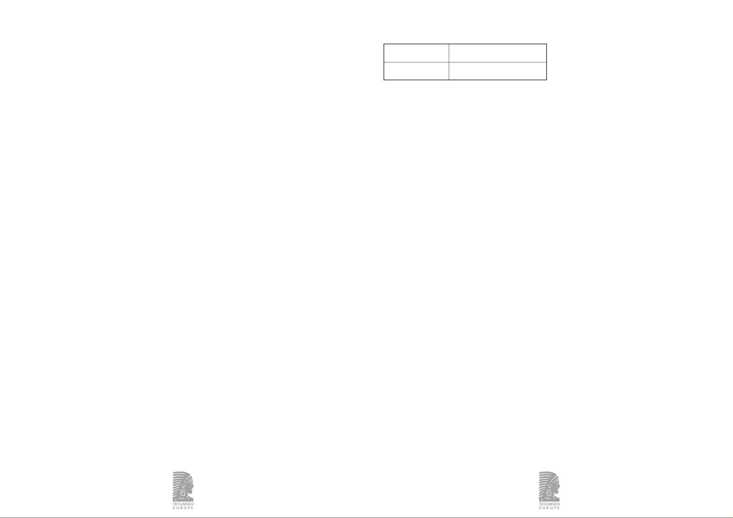
42/55
P
ar de atornillado de los kits de acoplamiento :
Kit de Par de atornillado máximo
acoplamiento (Nm – cm.kg)
ø 1/4” 20 – 203
ø 3/8” 30 – 305
Elección del deshidratador:
En caso de cambio del deshidratador, sustitúyalo por un
deshidratador de capacidad equivalente.
5 - GARANTÍA
Para cualquier información sobre la garantía del grupo,
consulte las “Condiciones Generales de Venta”.
6 - DECLARACIÓN DE CONFORMIDAD
Nuestros grupos de condensación de aire no se ven
directamente afectados por la Directiva 97/23/CE.
Estos grupos no deben considerarse un conjunto como el
definido en el articulo 1, paragráfo 2.1.5. Como resultado
de lo anterior, los grupos de condensación son evaluados,
concebidos, fabricados y documentados para ser
incorporados al mercado como un subconjunto siempre
compatible con las recomendaciones de la Directiva y que
puede ser incorporado a un conjunto.
7 - DECLARACIÓN DE INCORPORACIÓN
Para incorporar nuestro producto en una máquina, se debe
cumplir con lo indicado en la Declaración de Incorporación
del Fabricante del reverso de esta hoja. Nuestros grupos de
condensación no se ven directamente afectados por la
Directiva de Equipos a Presion 97/23/CE, sino que deben
considerarse un subconjunto compatible.
Los tubos incorporados a los modelos para montaje en
paralelo son conformes a la Directiva de Equipos a Presión
97/23/CE del 29 mayo de 1997, cláusula 3, paragráfo 3.
Con el fin de poder mejorar permanentemente estos
productos, TECUMSEH EUROPE S.A. se reserva el derecho
de modificar estas instrucciones sin previo aviso.
43/55
3.5 Puesta en servicio
ESTANQUEIDAD DEL CIRCUITO
Deberá llevarse a cabo una búsqueda sistemática de fugas en
todas las conexiones efectuadas, con la ayuda de un detector
electrónico de fugas.
VACÍO
Haga el vacío en la instalación para alcanzar una presión
residual de unos 200 micrómetros de mercurio, lo que
garantiza una buena calidad del vacío.
Se aconseja hacer el vacío simultáneamente en los circuitos
de alta y de baja presión. Esto permite reducir el tiempo de
la operación y asegurar un nivel idéntico de vacío en la
totalidad del circuito.
CARGA DEL FLUIDO FRIGORÍFICO
Cargue la instalación exclusivamente con el fluido frigorífico
para el que ha sido diseñado el grupo (véase placa de
características).
La carga del fluido frigorífico se hará siempre en fase líquida
a fin de conservar la buena proporción de la mezcla.
No ponga nunca en marcha el compresor si no se ha anulado
el vacío, tanto en AP como en BP. Para ello, se aconseja
cargar lentamente el circuito frigorífico entre 4 y 5 bar en el
R-404A, y unos 2 bar en el R-134a.
El complemento de la carga se hará hasta obtener el régimen
de funcionamiento nominal de la instalación. Consulte el
párrafo “Verificación antes de la puesta en marcha” antes de
conectar la electricidad.
VERIFICACIÓN ANTES DE LA PUESTA EN MARCHA
1. Compatibilidad de la tensión de alimentación con la del
grupo.
2. Calibración de los órganos de protección eléctrica.
3. Abertura total de las válvulas de servicio.
4. Funcionamiento de la resistencia del cárter o de la banda
calefactora.
5. Rotación libre de la hélice del ventilador del condensador.
6. Inspección de la instalación para descubrir posibles
anomalías.
VERIFICACIÓN DESPUÉS DE LA PUESTA
EN MARCHA
Lleve a cabo las verificaciones siguientes, pasadas algunas
horas de funcionamiento.
1. Tensión e intensidad consumida por el grupo.
2. Presión de la instalación en alta y en baja.
3. Rotación del ventilador del condensador.
4. Sobrecalentamientos.
5. Repita la búsqueda de fugas.
Asegúrese del buen funcionamiento global de la instalación.
Haga una inspección general de la instalación (limpieza,
ruidos anormales).
Vuelva a montar el carenado y fíjelo. Verifique que no hay
vibraciones.
4 - MANTENIMIENTO
Limpieza del intercambiador y del grupo una vez al año
como mínimo.
Búsqueda de fugas una vez al año, como mínimo, o en función
de la reglamentación local. Verifique periódicamente:
- Los órganos de seguridad y de regulación.
- El estado de las conexiones eléctricas y frigoríficas
(reapriete, oxidación, etc.).
- Las condiciones de funcionamiento.
- Las fijaciones del grupo sobre su soporte.
- Las fijaciones del carenado para que no vibre.
- El funcionamiento de la resistencia del cárter o de la banda
calefactora.
Mini-presostatos:
Los presostatos con valor fijo tienen un par de apriete
comprendido entre 13 Nm y 16 Nm (132 cm·kg a 163 cm·kg).
El diseño del acoplamiento hace inútil la utilización de una
junta de cobre para asegurar la estanqueidad.
Presostatos regulables:
Los acoplamientos flexibles, de los que están provistos los
presostatos regulables, tienen un par de apriete comprendido
entre 10 Nm y 12 Nm (102 cm·kg a 122 cm·kg). La
estanqueidad está asegurada por una junta de cobre. Es
aconsejable cambiarla cada vez que se desmonte un
acoplamiento flexible.
Deshidratador:
Los grupos carenados están equipados con un deshidratador
atornillable conectado a los kits de acoplamiento. La
estanqueidad está asegurada por una junta de cobre. Es
aconsejable cambiarla cada
vez que se desmonte.
366304a/10.02 366304a/10.02
Page 23

ANNEXE 1 – SCHÉMAS FRIGORIFIQUES / ANNEXE 1 – REFRIGERATION CIRCUITS
ANHANG 1 – KÄLTEKREISLÄUFE / ANEXO 1 – ESQUEMAS FRIGORÍFICOS
Petit carénage (650x500x460) - Famille CAE / CAET / CAJ / CAJT / TAJ / TAJT
Small casing (650mm x 500mm x 460mm) - CAE / CAET / CAJ / CAJT / TAJ / TAJT range
Kleines Gehäuse (650x500x460) – Versionen CAE / CAET / CAJ / CAJT / TAJ / TAJT
Carenado pequeño (650x500x460) - Familia CAE / CAET / CAJ / CAJT / TAJ / TAJT
Moyen carénage (830x700x570) - Famille CAJ / CAJT / TAJ / TAJT
Middle casing (830mm x 700mm x 570mm) - CAJ / CAJT / TAJ / TAJT range
Mittleres Gehäuse (830x700x570) - Versionen CAJ / CAJT / TAJ / TAJT
Carenado mediano (830x700x570) - Familia CAJ / CAJT / TAJ / TAJT
Moyen carénage (830x700x570) - Famille FH / FHT/ TFH / TFHT
Middle casing (830mm x 700mm x 570mm) - FH / FHT / TFH / TFHT range
Mittleres Gehäuse (830x700x570) - Versionen FH / FHT / TFH / TFHT
Carenado mediano (830x700x570) - Familia FH / FHT / TFH / TFHT
RÉFÉRENCES DÉSIGNATIONS
B1 Bouteille
BP Pressostat basse pression
Cd1 Condenseur
CP1 Compresseur
D1 Déshydrateur
HBP Pressostat haute et basse pression
HP Pressostat haute pression
V1 Voyant liquide
VA1 Vanne aspiration
VA2Vanne refoulement compresseur
VA3Vanne bouteille
45/5544/55
REFERENCES DESCRIPTIONS
B1 Accumulator
BP LBP pressure switch
Cd1 Condenser
CP1 Compressor
D1 Drier
HBP HBP and LBP pressure switch
HP HBP pressure switch
V1 Sight glass
VA1 Suction valve
VA2Liquid line valve compressor
VA3Accumulator valve
REFERENCIAS DESIGNACIONES
B1 Acumulador
BP Presostato baja presión
Cd1 Condensador
CP1 Compresor
D1 Deshidratador
HBP Presostato alta y baja presión
HP Presostato alta presión
V1 Mirilla
VA1 Válvula aspiración
VA2 Válvula descarga compresor
VA3 Válvula del acumulador
366304a/10.02 366304a/10.02
REFERENZ BEZEICHNUNG
B1 Sammler
BP Niederdruck Pressostat
Cd1 Verflüssiger
CP1 Verdichter
D1 Trockner
HBP Hoch-und Niederdruck Pressostat
HP Hochdruck Pressostat
V1 Schauglas
VA1 Saugventil
VA2Druckventil Verdichter
VA3 Sammlerventil
CP1
Cd1
V1 D1 VA3
B1
VA1
HBP
CP1
Cd1
V1 D1 VA3
B1
VA1 VA2
HBP
BP
CP1
Cd1
HP
V1 D1 VA3
B1
Page 24

47/55
ANNEXE 2 – SCHÉMAS ÉLECTRIQUES / ANNEXE 2 – CIRCUIT DIAGRAMS
ANHANG 2 – ELEKTRISCHE SCHALTBILDER / ANEXO 2 – ESQUEMAS ELÉCTRICOS
CAE - CAET (CSIR) CAJ - CAJT (CSIR)
46/55
CAE - CAET - CAJ - CAJT (CSR)
TAJ - TAJT
CAE - CAET - CAJ - CAJT (CSR)
TFH - TFHT
REFERENCES DESCRIPTIONS
BPB Pressostat BP
BPH Pressostat HP
BPBPH Pressostat HP/ BP
BTI Thermostat interne
C1 Condensateur démarrage
C2 Condensateur permanent
F1 – F2 Protecteur thermique
KM Relais
M1 Compresseur
M2 Ventilateur condenseur
R1 Ceinture chauffante
R2 Résistance de carter PTC
R3 Résistance de décharge
366304a/10.02 366304a/10.02
Pressostat BP réglable
avec un mini pressostat HP
Pressostat combiné
HP/BP
REFERENCES DESCRIPTIONS
BPB LBP pressure switch
BPH HBP pressure switch
BPBPH HBP/ LBP pressure switch
BTI Internal thermostat
CI Start, condenser
C2 Operation, condenser
F1-F2 Thermal protection
KM Relay
M1 Compressor
M2 Ventilator, condenser
R1 Heat band
R2 Crankcase heater PTC
R3 Bleeder resistor
REFERENCIAS DESIGNACIONES
BPB Presostato BP
BPH Presostato AP
BPBPH Presostato AP/ BP
BT1 Termostato interno
C1 Condensador de arranque
C2 Condensador permanente
F1 – F2 Protector térmico
KM Relé
M1 Compresor
M2 Ventilador del condensador
R1 Banda calefactora
R2 Resistencia del cárter PTC
R3 Resistencia de descarga
REFERENZ BEZEICHNUNG
BPB ND Pressostat
BPH HD Pressostat
BPBPH HD/ ND Pressostat
BTI Wicklungsthermostat
CI Anlaufkondensator
C2 Betriebskondensator
F1-F2 Thermischer Schutz
KM Relais
M1 Verdichter
M2 Verflüssigerlüfter
R1 Heizband
R2 Kurbelwannenheizung PTC
R3 Entladungswiderstand
Page 25

49/5548/55
ANNEXE 2 – Schémas électriques option coffret électrique avec sectionneur
ANNEXE 2 – Circuit diagrams, option with electrical box and isolating switch
ANHANG 2 – Elektrische Schaltbilder, Ausführung Anschlusskasten mit Schaltschütz
ANEXO 2 – Esquemas eléctricos opcionales, caja eléctrica con seccionador
CAE - CAET - CAJ - CAJT (CSIR) CAE - CAET - CAJ - CAJT (CSR)
TAJ - TAJT
FH - FHT (CSR)
TFH - TFHT
366304a/10.02 366304a/10.02
Pressostat combiné
réglable HP/BP
Pressostat BP réglable
avec un mini pressostat HP
RÉFÉRENCES DÉSIGNATIONS
BPB Pressostat BP
BPH Pressostat HP
BPHPB Pressostat HP/BP
BTI Thermostat interne
C1 Condensateur démarrage
C2 Condensateur permanent
F1 – F2 Protecteur thermique
KM Relais
M1 Compresseur
M2 Ventilateur condenseur
QM1 Interrupteur / sectionneur
R1 Ceinture chauffante
R2 Résistance de carter PTC
R3 Résistance de décharge
REFERENCES DESCRIPTIONS
BPB LBP pressure switch
BPH HBP pressure switch
BPBPH HBP/ LBP pressure switch
BTI Internal thermostat
CI Start, condenser
C2 Operation, condenser
F1-F2 Thermal protection
KM Relay
M1 Compressor
M2 Ventilator, condenser
QMI Contactor / isolator
R1 Heat band
R2 Crankcase heater PTC
R3 Bleeder resistor
REFERENCIAS DESIGNACIONES
BPB Presostato BP
BPH Presostato AP
BPBPH Presostato AP/ BP
BT1 Termostato interno
C1 Condensador de arranque
C2 Condensador permanente
F1 – F2 Protector térmico
KM Relé
M1 Compresor
M2 Ventilador del condensador
QMI Interruptor / seccionador
R1 Banda calefactora
R2 Resistencia del cárter PTC
R3 Resistencia de descarga
REFERENZ BEZEICHNUNG
BPB ND Pressostat
BPH HD Pressostat
BPBPH HD/ ND Pressostat
BTI Wicklungsthermostat
CI Anlaufkondensator
C2 Betriebskondensator
F1-F2 Thermischer Schutz
KM Relais
M1 Verdichter
M2 Verflüssigerlüfter
QMI Überstraumslöser
R1 Heizband
R2 Kurbelwannenheizung PTC
R3 Entladungswiderstand
Page 26

ANNEXE 3 – Implantation groupes carénés
ANNEXE 3 – Location of condensing units with casing
ANHANG 3 – Standort von Verflüssigungssätzen mit Gehäuse
ANEXO 3 – Disposición en planta de los grupos carenados
A : Sens du flux d'air - Air flow direction - Luftstromrichtung - Sentido de la circulación del aire.
ANNEXE 4 – Fixations groupes carénés / ANNEXE 4 – Fixing of condensing units with casing
ANHANG 4 – Befestigung von Verflüssigungssätzen mit Gehäuse
ANEXO 4 – Fijación de los grupos carenados
Fixation au sol / Ground fixing Fixation murale / Wall fixing
Bodenkonsole / Fijación al suelo Wandkonsole / Fijación mural
DIMENSIONS / DIMENSIONS / ABMESSUNGEN / DIMENSIONES
Dimensions
carénages A B C D E F G H
(mm)
650x500x460 315 290 250 20 395 443 115 30
830x700x570 495 488 420 35 510 630 95 35
Dimensions
casings A B C D E F G H
(mm)
650x500x460 315 290 250 20 395 443 115 30
830x700x570 495 488 420 35 510 630 95 35
Abmessungen
Gehäuse A B C D E F G H
(mm)
650x500x460 315 290 250 20 395 443 115 30
830x700x570 495 488 420 35 510 630 95 35
Dimensiones:
del carenado A B C D E F G H
(mm)
650x500x460 315 290 250 20 395 443 115 30
830x700x570 495 488 420 35 510 630 95 35
366304a/10.02 366304a/10.02
50/55 51/55
Page 27

53/55
ANNEXE 5 – Démontage / remontage du carénage
ANNEXE 5 – Mounting and demounting of the casing
ANHANG 5 – Auf- und Abbau der Gehäuse
ANEXO 5 – Desmontaje y montaje del carenado
RÉFÉRENCES DÉSIGNATIONS
1Câble alimentation électrique groupe
2Tube aspiration groupe
3Tube refoulement groupe
REFERENCES DESCRIPTIONS
1 Power supply cable Condensing unit
2 Suction line Condensing unit
3Liquid line Condensing unit
REFERENZEN BEZEICHNUNGEN
1Stromversorgungskabel
Verflüssigungssatz
2 Saugleitung Verflüssigungssatz
3Druckleitung Verflüssigungssatz
REFERENCIAS DESIGNACIONES
1Cable alimentación eléctrica de grupo
2Tubo aspiración del grupo
3Tubo descarga del grupo
366304a/10.02 366304a/10.02
ANNEXE 6 – Passage tuyauterie et câble alimentation
ANNEXE 6 – Piping and power supply
ANHANG 6 – Rohrleitungen und Stromversorgung
ANEXO 6 – Paso de las tuberías y del cable de alimentación
1
2
3
52/55
Page 28

55/5554/55
ANNEXE 7 – Information boitier électrique
ANNEXE 7 – Electrical box information
ANHANG 7 – Information elecktrischer Schaltkasten
ANEXO 7 – Información caja de conexiones eléctricas
ANNEXE 8 – Information vannes
ANNEXE 8 – Valve information
ANHANG 8 – Information Ventile
ANEXO 8 – Información válvulas
A- Process connection
B - Pressure switch connection
C - Release the shaft seal nut before use
- Tighten the shaft seal after use
8,5/11,5 N.m
85/115 Cm.kg
6/11,5 N.m
60/115 Cm.kg
A- Raccordement vide ou charge
B - Raccord pressostatique
C - Débloquer l’écrou de presse étoupe
avant manipulation du pointeau
Resserer l’écrou de presse étoupe
366304a/10.02 366304a/10.02
TIREZ ICI POUR OUVRIR
PULL HERE TO OPEN
ZUM ÖFFNEN HIER ZIEHEN
TIRAR AQUÍ PARAABRIR
ATTENTION : FONCTIONNE EN POSITION VERTICALE SEULEMENT
WARNING: USE ONLY ON THE VERTICAL POSITION
Dimensions Boîtier JUNIOR Boîtier SENIOR
L 125 180
H 206 232
P8290
X91130
Y6065
A94154
B1212
 Loading...