

Tecumseh AWG4516EXTXF Performance Data Sheet
Tecumseh Compressor Company
March 16, 2011
Indoor Condensing Units
Model: AWG4516EXTXF BoM: 2B1170-1 R-22 1 1/2 HP AIRCOOLED
Model
AWG4516EXTXF
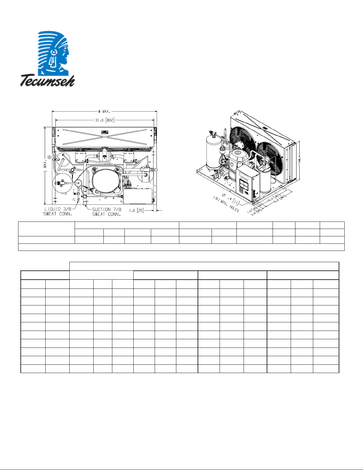
* F = Flare, S = Solder, RF or RS = Rotolock with Flare or Solder Connections, C = Compression Fitting
Evaporator T
°F PSIG BTUH Watts Cond T BTUH Watts Cond T BTUH Watts Cond T BTUH Watts Cond T
10 32.8 6539 1087 90 5903 1062 99 5298 1068 108 4693 1084 117
15 37.7 7678 1143 91 6985 1131 101 6298 1146 110 5630 1168 119
20 43.0 9020 1198 93 8239 1199 102 7458 1224 111 6682 1253 120
25 48.7 10547 1253 96 9637 1267 104 8750 1302 113 7866 1337 122
30 54.8 12173 1307 98 11160 1335 107 10153 1380 115 9147 1422 124
35 61.4 13950 1361 100 12798 1403 109 11647 1458 117 10552 1504 126
40 68.5 15867 1414 103 14568 1469 111 13220 1535 120 11933 1589 128
45 76.0 17793 1470 106 16396 1535 114 14944 1606 122 13498 1667 130
50 84.0 19845 1524 108 18213 1604 116 16586 1683 124 15048 1746 132
55 92.6 21963 1576 111 20143 1667 118 18330 1754 126 16531 1825 134
25.0 33.5 19.5 19.5 7/8” S 3/8” S 19 lbs 1800 38.5 190
Dimensions, inches Line Connection* Pumpdown Air Oil Ch Gr. Wt.
L W H CH Suction Liquid
80F 90F 100F 110F
Return gas temp. 65F, 5F sub cooling
90 F 90%
Ambient Temperatures
SCFM Oz. Lbs.
60 Hz Performance
March 16, 2011
Specifications/ Parts:
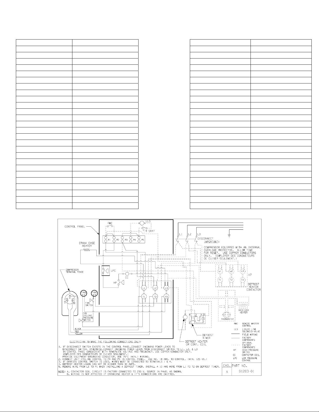
Model AWG4516EXTXF Unit Bill of Material 2B1170-1 Fan Motor RLA 0.7 Each Nominal Volts-Hz-Ph 200-230-60-3 Fan Blade 51568-1 (2) Refrigeration Range 20° to 55° Fan Guard 70831 (2) Design Pressure Low 150 Fan Shroud 70648-2 Design Pressure High 450 High Pressure Switch 84095-1 Voltage Range 180 to 254 Low Pressure Control 84026-2 Min. Circuit Ampacity 8.7 Oil Separator * 704-00002 Max. Fuse Size (amps) 15 Condenser 50855-1 Compressor Model AWG5515EXT Fan Switch 84096-1 Comp. Bill of Material AW700RT-120-A2 Fan Switch 84096-2 Compressor RLA/LRA 5.6 / 51.0 Overload INTERNAL Liquid Valve 31592 Relay N/A Liquid Filter * 70081 Run Capacitor N/A Sight Glass * 70084 Run Capacitor Rating N/A Suction Valve * 31529-1 Start Capacitor N/A Rotolock Valve Gasket 30233 Start Capacitor Rating N/A Discharge Valve 56596 Contactor 91014 Suction Filter * 70082 Unit Drawing DGU1918-58 Accumulator * TK00042000 Wiring Diagram 91263-01 Crankcase Heater 91022-1 Defrost Timer * N/A Suction Shut Off Valve* 56500-K14 Liquid Shut Off Valve* 56500-K06 Shrader Valve Body* 56510 Valve Core* 56552 * = Equipped Units Only
Fan Motor 810F050C20 (2)
Receiver Tank 51082-1
Electrical Diagram
 Loading...