

Page 1
Tecumseh Compressor Company
Indoor Condensing Units
July 11, 2016
Revision: Rel
Model: AGA4572WXNXC BoM: 2A6017-1 R-22/R-407C 6 HP AIRCOOLED
Model
AGA4572WXNXC
* F = Flare, S = Solder, RF or RS = Rotolock with Flare or Solder Connections, C = Compression Fitting
Ambient Temperatures
Evaporator T, 90°F 100°F 110°F
°F PSIG BTUH Watts Cond T BTUH Watts Cond T BTUH Watts Cond T
20 43.0 44000 5920 109.7 39400 6020 118.1 34700 6070 126.9
30 54.8 55000 6570 114.4 50000 6720 121.9 45100 6920 130.2
40 68.5 67000 7370 118.1 62500 7570 125.8 57400 7820 135.0
45 76.0 72000 7820 120.8 67500 8070 129.1 62100 8270 137.1
50 84.0 80000 8220 123.3 75000 8540 130.2 70100 8770 139.0
R-22 Capacity Performance @ 60 Hz, Return Gas Temperature 650F, Sub Cooling 50F, shown above
R-407C Capacity Performance Factor: 0.87 (Multiply the R-22 BTU/Hr by 0.87 to determine the Capacity of R-407C)
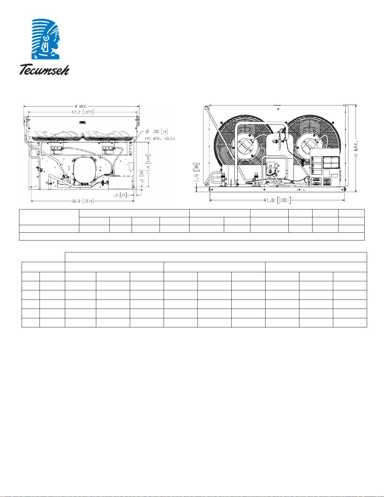
28.6 44.9 26.9 --- 7/8” S 1/2” S 51.33 lbs 4200 65 395
Dimensions, inches Line Connection* Pumpdown Air Oil Ch Gr. Wt.
L W H CH Suction Liquid
90 F 90%
SCFM Oz. Lbs.
Page 2
July 11, 2016
Revision: Rel
Specifications/ Parts:
Model AGA4572WXNXC
Unit Bill of Material 2A6017-1 Fan Motor RLA 1.9 Each
Nominal Volts-Hz-Ph 208-230/60/1 Fan Blade 51528-3 (2)
Refrigeration Range 20° to 50°F Fan Guard 70832 (2)
Design Pressure Low 150 Fan Shroud 70611-1
Design Pressure High 450 High Pressure Switch 84095-1
Voltage Range 187 to 254 Low Pressure Control 84026-2
Min. Circuit Ampacity 47.3 Oil Separator * N/A
Max. Fuse Size (amps) 80 Condenser 50777-6
Compressor Model AGA5568WXN Fan Switch 84096-1
Comp. Bill of Material AG144GT-002-J7 Fan Switch 84096-2
Compressor RLA/LRA 34.6 / 179.0 Receiver Tank 51083
Overload INTERNAL Liquid Valve 56596
Relay 8200RVAM12 Liquid Filter * N/A
Relay Replacement Kit K71-20 Sight Glass * N/A
Run Capacitor 85PR440E90 Suction Valve * N/A
Start Capacitor 85PS330D16 Rotolock Valve Gasket N/A
Run Cap Replacement Kit K150-22 Discharge Valve 56596
St Cap Replacement Kit K146-43 Suction Filter * N/A
Contactor 91012H Accumulator * N/A
Unit Drawing DGU1901-44 Crankcase Heater 90699
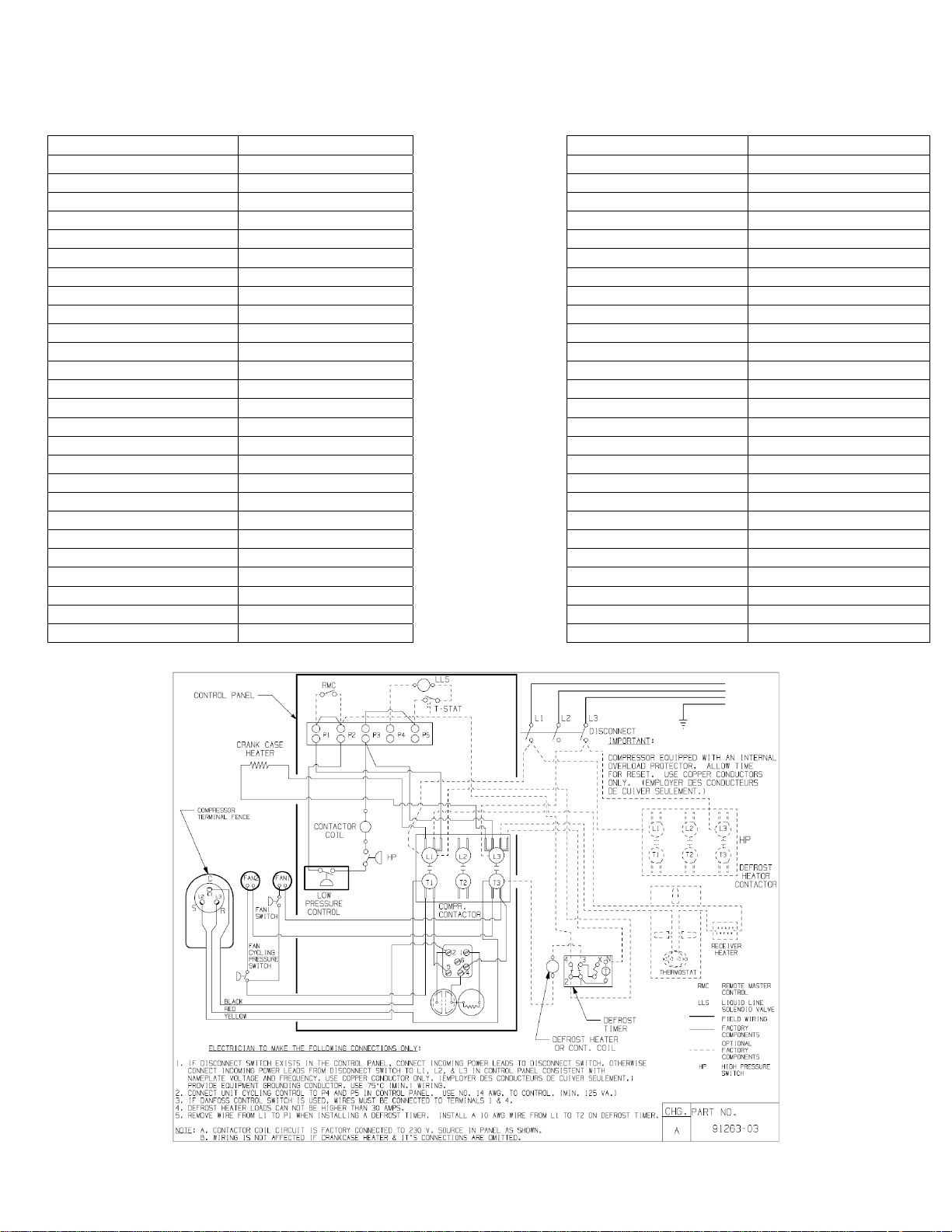
Wiring Diagram 91263-03 Defrost Timer * N/A
* = Equipped Units Only
Options for Equipped Units
Receiver Heater N/A
Solenoid Valve N/A
Fan Motor 810S186B40 (2)
Electrical Diagram
EC73052
 Loading...