

Page 1
Tecumseh Compressor Company
Indoor Condensing Units
July 8, 2016
Revision: Rel
Model: AGA4560WXNXC BoM: 2A5127-1 R-22/R-407C 5 HP AIRCOOLED
Model
AGA4560WXNXC
* F = Flare, S = Solder, RF or RS = Rotolock with Flare or Solder Connections, C = Compression Fitting
Evaporator T
°F PSIG BTUH Watts Cond T BTUH Watts Cond T BTUH Watts Cond T BTUH Watts Cond T
20 43.0 44770 4930 103 41457 5017 109 37575 5115 117 33100 5220 126
25 48.8 49238 5327 104 45113 5411 111 40700 5516 119 36600 5651 128
30 54.8 52813 5720 105 49438 5810 112 45500 5925 120 41000 6080 129
35 61.5 56647 6047 106 53516 6166 113 49788 6313 121 45350 6500 132
40 68.5 60532 6372 108 57544 6524 115 53975 6705 123 49700 6920 133
45 76.0 65059 6734 110 62003 6948 117 58313 7173 125 53800 7370 135
50 84.0 67782 7128 113 64844 7343 120 61350 7580 128 57200 7820 139
55 92.6 70505 7441 115 67877 7697 122 64432 7988 130 59600 8300 140
R-22 Capacity Performance @ 60 Hz, Return Gas Temperature 650F, Sub Cooling 50F, shown above
R-407C Capacity Performance Factor: 0.87 (Multiply the R-22 BTU/Hr by 0.87 to determine the Capacity of R-407C)
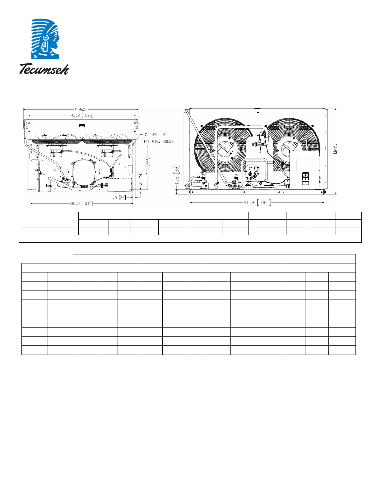
28.6 44.9 26.9 --- 7/8” S 1/2” S 51.33 lbs 4200 65 463
Dimensions, inches Line Connection* Pumpdown Air Oil Ch Gr. Wt.
L W H CH Suction Liquid
Ambient Temperatures
80F 90F 100F 110F
90 F 90%
SCFM Oz. Lbs.
Page 2
July 8, 2016
Revision: Rel
Specifications/ Parts:
Model AGA4560WXNXC
Unit Bill of Material 2A5127-1 Fan Motor RLA 1.9 Each
Nominal Volts-Hz-Ph 208-230/60/1 Fan Blade 51528-3 (2)
Refrigeration Range 20° to 55°F Fan Guard 70832 (2)
Design Pressure Low 150 Fan Shroud 70611-1
Design Pressure High 450 High Pressure Switch 84095-1
Voltage Range 187 to 254 Low Pressure Control 84026-2
Min. Circuit Ampacity 42.1 Oil Separator * N/A
Max. Fuse Size (amps) 70 Condenser 50777-6
Compressor Model AGA5561WXN Fan Switch 84096-1
Comp. Bill of Material AG133GT-001-J7 Fan Switch 84096-2
Compressor RLA/LRA 30.5 / 165.0 Receiver Tank 51083
Overload INTERNAL Liquid Valve 56596
Relay 8200RVAM14 Liquid Filter * N/A
Relay – Replacement Kit K71-20 Sight Glass * N/A
Run Capacitor 85PR440E90 Suction Valve * N/A
Run Cap Replacement Kit K150-22 Rotolock Valve Gasket N/A
Start Capacitor 85PS330D16 Discharge Valve 56596
Start Capacitor Kit K146-43 Suction Filter * N/A
Contactor 91013 Accumulator * N/A
Unit Drawing DGU1901-44 Crankcase Heater 90699
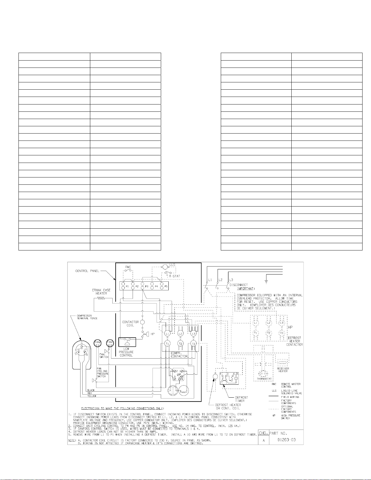
Wiring Diagram 91263-03 Defrost Timer * N/A
* = Equipped Units Only
Options for Equipped Units
Receiver Heater N/A
Solenoid Valve N/A
Fan Motor 810S186B40 (2)
Electrical Diagram
EC73052
 Loading...