

Tecumseh 5267-1900 Owner's Manual
OWNER'S MANUAL
32"- 5 H.P. RIDING MOWER
MODEL 5267-1900
WARRANTY
Lawn Mower Division Warranty Policy.
ONE YEAR LIMITED WARRANTY
For one (1) year from date of purchase by the first'consumer for residential use (thirty (30) days
commercial use), Lawn Mower Division warrants that it will replace free of charge, including
labor, any original part of anyLawn Mower Division product found to be defective by any
authorized Service Dealer or the factory, except the battery which isWarranted for ninety (90) days
from date of purchase.
1
This warranty does not cover engines, transmissions,_trensaxles or differentials (these items are
covered by their manufacturer's own warranty). This warranty does not cover parts that have
faile d due to normal wear or parts that have failed subject to misuse or abuse. Transportation of
the unit or parts to and from an authorized Service Dealer or the factory is the responsibility ofthe
owner.
A step by step explanation as to what procedure should be followed for this Warranty is;
1. If a part becomes defective, contact t_te store where the unit was purchased for the name
and address of the authorized Service Dealer nearest to you.
2. If you cannot locate an authorized Service Dealer, write Service Department of Lawn Mower
Division, for the name and address of the authorized Service Dealer in your area.
3. Return the defective productoalong with proof of purchase to such authorized Service Dealer
for replacement of any defective part where covered by this warranty.
There is no other express warranty. Implied warranties, including those of merchantability and
fitness for a particular purpose are limited to one (1) year from date of purchase. Liability for
incidental or consequential damages are excluded.
Some states do not allow limitations on how long an implied warranty lasts, so the above
limitation may not apply to you. Some states do not allow the exclusion of incidental or
consequential damages, so the above exclusion may not apply to you. This warranty gives you
specific legal rights, and you may have other rights which vary from state to state.
Lawn Mower Division
P.O. Box 377 Des Moines. Iowa 50302
'UNIT PARTS AND SERVICE
This manual contains instructions for safety, assembly and maintenance. Read this manual carefully and
completely so that you will know proper assembly, use and care of your unit. Also fill in and mail the warranty
registration card packed with the unit. For service other than covered in this manual, contact an authorized
service dealer. A nationwide parts and service organization has been established to provide locally available
parts and service. A list of authorized parts distributors has been included in this manual. When ordering
repair parts, always give the following information: 1. The Part Name; 2. The Part Number; 3. The
Quantity desired; 4. The Full (eight digit) Model Number of the unit. The model number will be found on a
plate attached to the unit.
Look for this symbol. It means -- ATTENTION! BECOME ALERT! A
HAZARD TO OPERATOR. BYSTANDERS, PROPERTY OR UNIT
MAY EXIST.
=art No. 62211 Rev. 3/82
LAWN MOWER DIVISION
P.O. BOX 377
DES MOINES. IOWA 50302
1182
Pwinlecl in U S A
It isimportant when using your Riding Mower that certain precautions betaken to
prevent injury or damage. Please read the following list of precautions before you
assemble or use yourRidingMower.
1. Know the controls and howto stop quickly. Read the
Owner's Manual. Wear safety glasses or eye shields when
assembling or operating unit.
2. Disengage ell attachment clutches, shift to neutral,
and set parking brake before attempting to start the en-
gine. Unless these steps are followed, the engine will not
start because of safety interlock or lockouts. When
starting your engine or mower equipped with a pull
starter, stand firm and make sure your feet are well away
from the blade(s).
3. When using vehicle with mower:
A. Do not operate this mower without either the
chute deflector or an entire grass catcher in place.
B. Mow only in daylight or good artificial light.
C. Never make a cutting height adjustment of
housing guide wheel while eKgine is running.
D. Shut engine off when removing grass catcher
and/or unclogging chute.
E. DO not operate mower when barefooted. Always
wear substantial footwear, preferably steel-toed
shoes. Do not wear loose fitting clothing that
could get caught in any moving parts. ,
F. Always keep clear of discharge chute or any
moving parts while engine is running.
4. Always place the blade control lever in a disengaged
position when not cutting grass, such as when crossing a
gravel driveway or roadway and when transporting the
mower.
5. Disengage power to attachments, stop engine,
remove ignition key. and set parking brake before leaving
operator position. AlWays dismount on the side away
from the discharge chute.
6. Handle gasoline with care; it is highly flammable.
A. Use only approved gasoline containers.
B. Never remove cap or add gasoline to a running or
hot engine or fill fuel tank indoors. Wipe up spilled
gasoline,
C. Check your fuel supply before each '_seallowing
space for expansion as the heat of the engine
and/or sun can cause gasline to expand.
D. Never store gasoline or equipment with gasoline
in the tank inside of a building where fumes may
reach an open flame or spark. Never stoze your
mower for prolonged periods {more than 15 days}
with gasoline in the tank, Store gasoline and your
mower in a locked, safe storage area secure from
children and others.
7. Allow engine to cool before storing in any enclosure.
8. To reduce fire hazard, keep engine free of grass,
leaves, or excessive grease.
9. Do not allow children to operate the mower. Never
allow adults to operate it without proper instructions.
10. Never attempt to carry passengers. TheiPsafsty, as
well as yours, may be in danger. Do not allow others,
including children and pets in the area while operating the
mower. Be especially watchful for children and passersby.
Place the blade control lever in • disengaged position and
stop the engine while others ere in the vicinity of:the
mower.
11. When using any attachments, never direct discharge
of material toward bystanders or allow anyone near the
vehicle while in operation.
12. Clear work area of objects which may be picked up
and discharged by the mower. {These include rocks,
stones, wires, cans, boards, branches, bones, and other
foreign objects).
13. Vehicles and attachments should be stopped and in-
spected for damage if vibration devolopes or after striking
a foreign object. Any damage should be repaired before
restarting and operating the equipment.
14. Stay alert for holes in terrain and other hidden
hazards. Exercise care when mowing around fixed objects
in order to prevent blade{s} from striking it. Never deliber-
ately run a power mower over any foreign object. Always
disengage blade control before attempting to remove the
mower from a hole or other obstruction.
15. Keep all nuts, bolts and screws tight to be sure equip-
ment is in safe working condition. Check blade mount
nuts or bolts for proper tightness at frequent intervals.
16. Keep vehicle and attachments in good opersting con-
dition and keep safety devices in place.
17. Disengage power to attachments, stop engine.
remove ignition k_y, set parking brake and remove spark
plug before working on any part of the mower or making
any adjustments.
18. Do not change engine governor settings or over-
speed engine.
1g. Check grass catcher bag frequently for wear end/or
deterioration. Replace with new bag for protection.
20. Do not stop or start suddenly, especially when going
uphill or downhill. Mow slowly when On slopes and mow
up and down the slope, never across it. On slopes, bevary
cautious and avoid sharp turns to prevent tipping or loss of
control. Exercise caution when changing direction on
slopes. Never operate your lawn mower in wet or slippery
grass where direction is unsure or at a speed which could
cause a skid. Avoid shifting gears on an incline whenever
possible, If necessary, be sure brake is epplled when
shifting.
21. Watch out for traffic when crossing or near
roadways.
22. Do not run the engine indoors. Open doors if engine
is run in garage. Exhaust fumes contain carbon monoxide
gas w_ich is odorless and a deadly poison.
23. Use care when pulling loads or using heavy equip-
ment.
A. Use'only approved drawbar hitch points.
B. Limit loads to those youcan safely control.
C. Do not turn sharply. Use care when backing.
D. Never shift gears to reverse your direction until
the mower comes to a complete stop. Do not
operate your mower with the parking brake :
engaged.
24. Take all possible precautions when leaving the
vehicle unattended, such as disengaging the power take-
off. lowering attachments, shifting into neutral, setting
the parking brake, stopping the engine, and removing the
key.
--2--
' Record the following information about your unit so that you will be able to provide it in case of loss or theft.
PURCHASE DATE: _MODEL NO.: 5267-1900 CODE NO.:
DEALER'S NAME & ADDRESS
CITY STATE TELEPHONE
WARNING
This unit is equipped with an internal combustion
engine and should not be used on or near any
unimproved forest-covered, brush-covered or
grass-covered land unless the engine's exhaust
system is equipped with a spark arrester meeting
app)icable state or local laws (if any). If a spark
arrester is used, it should be maintained in effective
working order by the operator.
CONTENTS OF SHIPPING CARTON
1 - 32 inch Riding Mower
1 - Steering Wheel (with roll pin partially installed)
1 - Engine Manual
TOOLS REQUIRED FOR ASSEMBLY
1 - '/2 inch Wrench (or adjustable wrench)
1 - 7/16 inch Wrench (or adjustable wrench)
1 - Hammer (plastic or rawhide preferred)
DANGER
The operation of any powered equipment can result
in foreign objects being thrown into the eyes, which
can result in severe eye damage. Always wear safety
glasses or eye shields while assembling or operating
power equipment.
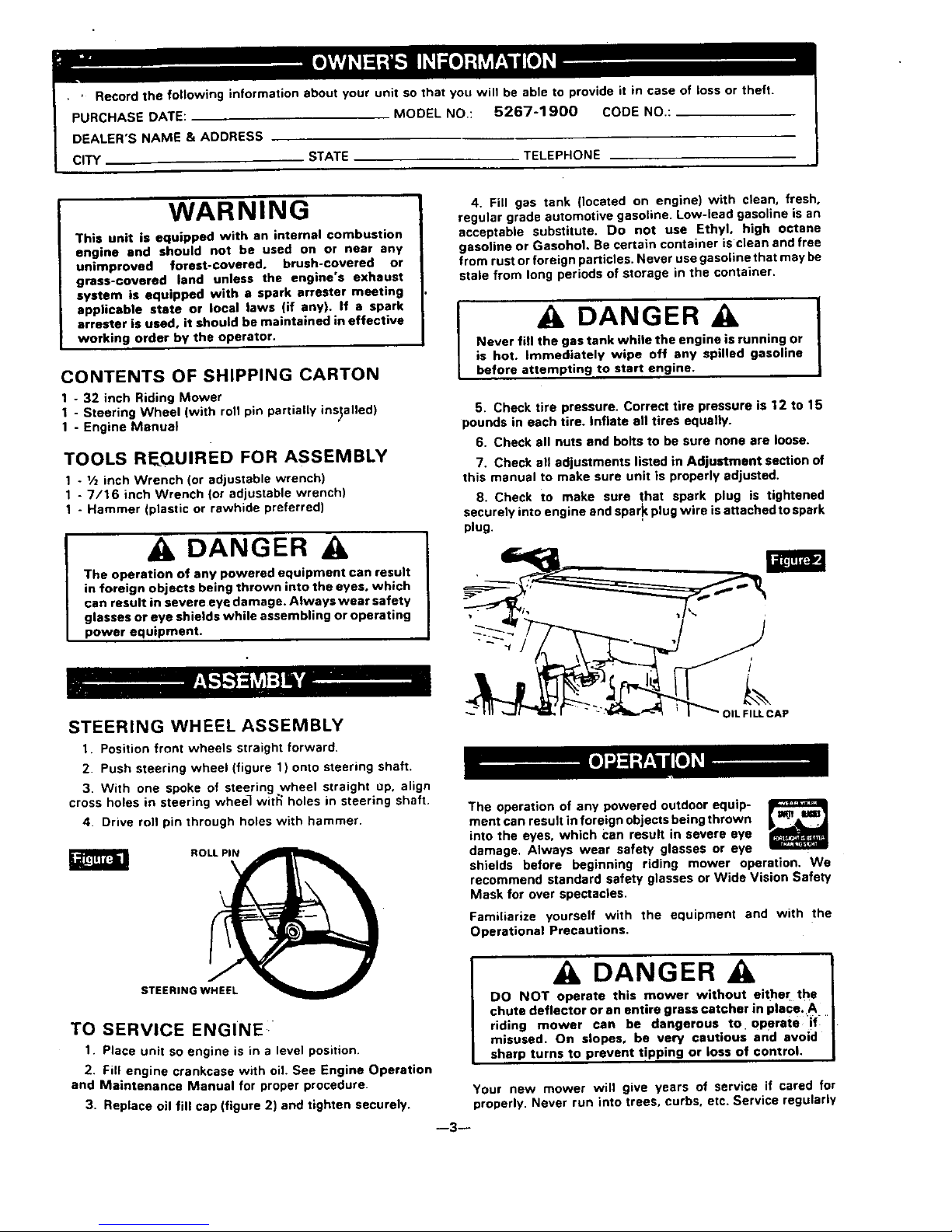
STEERING WHEEL ASSEMBLY
1. Position front wheels straight forward.
2. Push steering wheel (figure 1) onto steering shaft.
3. With one spoke of steering wheel straight 0p, align
cross holes in steering wheel wit_ holes in steering shaft.
4. Drive roll pin through holes with hammer.
ROLL PIN
I
4. Fill gas tank (located on engine) with clean, fresh,
regular grade automotive gasoline. Low-lead gasoline is an
acceptable substitute. Do not use Ethyl, high octane
gasoline or GasohoL Re certain container is clean and free
from rust or foreign particles. Never use gasoline that may be
stale from long periods of storage in the container.
DANGER A
Never fill the gas tank while the engine is running or
is hot. Immediately wipe off any spilled gasoline
before attempting to start engine.
I
5. Check tire pressure. Correct tire pressure is 12 to 15
pounds in each tire. Inflate all tires equally.
6. Check all nuts and bolts to be sure none are loose.
7. Check all adjustments listed in Adjustment section of
this manual to make sure unit is properly adjusted.
8. Check to make sure that spark plug is tightened
securely into engine and spark plug wire is attached to spark
plug.
/
OIL FILL CAP
The operation of any powered outdoor equip-
ment can result in foreign objects being thrown
into the eyes, which Can result in severe eye
damage, Always wear safety glasses or eye
shields before beginning riding mower operation. We
recommend standard safety glasses or Wide Vision Safety
Mask for over spectacles.
Familiarize yourself with the equipment and with the
Operational Precautions.
STEERING WHEEL
TO SERVICE ENGINE
1. Place unit so engine is in a level position.
2. Fill engine crankcase with oil. See Engine Operation
and Maintenance Manual for proper procedure.
3. Replace oil fill cap (figure 2) and tighten securely.
A DANGER A
DO NOT operate this mower without either the
chute deflector or an entire grass catcher in place. A
riding mower can be dangerous to operate if
misused. On slopes, be very cautious and avoid
sharp turns to prevent tipping or loss of control.
Your new mower will give years of service if cared for
properly. Never run into trees, curbs, etc. Service regularly
--3--
and store in dry area. Operate your mower at slow speeds
until you become familiar with the machine. Avoid sharp
turns at high speed and uphill or downhill turns. Operate
mower carefully. Be especially cautious on hills• When
riding down inclines, keep shift control in low speed with
brake-clutch pedal out. This helps the engine control the
speed. Use brake for fast stops on hills.
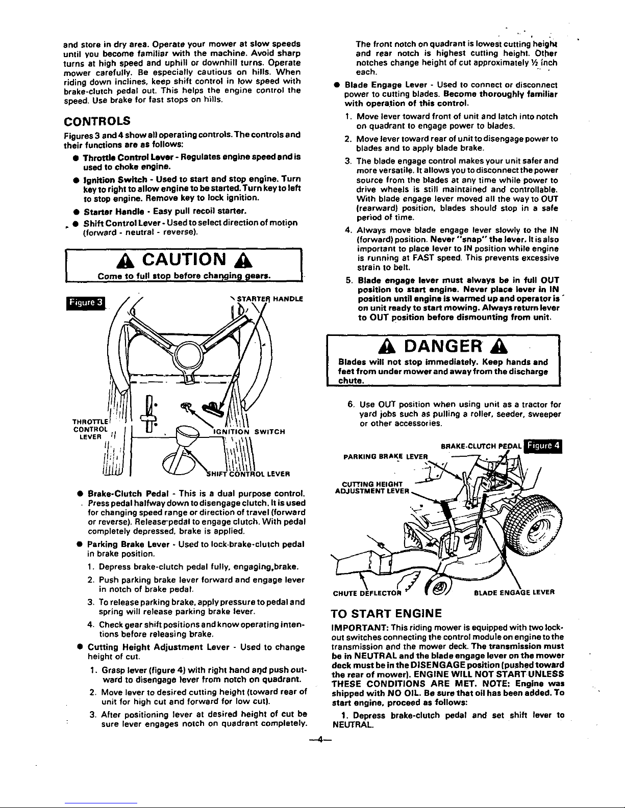
CONTROLS
Figures 3 and 4 show all operating controls.The controls end
their functions are as follows:
• Throttle Control Lever - Regulates engine speed and is
used to choke engine.
• Ignition Switch - Used to start end stop engine. Turn
key to right to allow engine to be started. Turn key to left
to stop engine. Remove key to lock ignition.
• Starter Handle - Easy pull recoil starter.
• • Shift Control Lever- Used to select direction of motion
(forward - neutral - reverse).
,
CAUTION
Come to full stop before char_gin_ _ears.
HANDLE
• f
The front notch on quadrant islowest cutting height
and rear notch is highest cutting height. Other
notches change height of cut approximately 1/2inch
each. "'"
• Blade Engage Lever - Used to connect or disconnect
power to cutting blades. Become thoroughly familiar
with opera,ion of this control.
1. Move lever toward front of unit and latch into notch
on quadrant to engage power to blades.
2. Move lever toward rearofunittodisengagepower to
blades and to apply blade brake.
3. The blade engage control makes your unit safer and
more versatile. It allows you todisconnect the power
source from the blades at any time while power to
drive wheels is still maintained and controllable•
With blade engage lever moved all the way to OUT
(rearward) position, blades should stop in a safe
period of time.
4. Always move blade engage lever slowly to the IN
(forward) position. Never *'snap" the lever, It is also
important to place lever to IN position while engine
is running at FAST speed. This prevents excessive
strain to belt.
5.
Blade engage lever must always be in full OUT
position to start engine. Never place lever in IN
position until engine is warmed up and operator is °
on unit ready to start mowing. Always return lever
to OUT position before dismounting from unit.
m
m
,
DANGER
Blades will not stop immediately. Keep hands and
feet from under mower and away from the discharge
chute.
I
THROTrLE
CONTROL !
IGNITION
SWITCH
LEVER 'l /
tl'!
!ti:, /
.EVEn
6. Use OUT position when using unit as a tractor for
yard jobs such as pulling a roller, seeder, sweeper
or other accessories.
BRAKE-CLUTCH PEDAL
PARKING BRAKE LEVER
• Brake-Clutch Pedal - This is a dual purpose control.
Press pedal halfway down to disengage clutch. It is used
for changing speed range or direction of travel (forward
or reverse). Release-pedal to engage clutch. With pedal
completely depressed, brake is applied.
CUl!', ING HEIGHT
ADJ
• Parking Brake Lever - Used to lock.brake-clutch pedal
in brake position.
1. Depress brake-clutch pedal fully, engaging,brake.
2. Push parking brake lever forward and engage lever
in notch of brake pedal.
3. To release parking brake, apply pressure to pedal and
spring will release parking brake lever.
4. Check gear shift positions and know operating inten-
tions before releasing brake.
• Cutting Height Adjustment Lever - Used to change
height of cuL
1. Grasp lever (figure 4) with right hand arid push out-
ward to disengage lever from notch on quadrant.
2. Move lever to desired cutting height (toward rear of
unit for high cut and forward for low cut).
3. After positioning lever at desired height of cut be
: sure lever engages notch on quadrant completely.
CHUTE DEFLECTOR
BLADE ENGAGE LEVER
TO START ENGINE
IMPORTANT: This riding mower is equipped with two lock-
out switches connecting the control module on engine tothe
transmission end the mower deck. The transmission must
be in NEUTRAL and the blade engage lever on the mower
deck must be in the DISEN GAG E position (pushed toward
the rear of mower). ENGINE WILL NOT START UNLESS
THESE CONDITIONS ARE MET. NOTE: Engine was
shipped with NO OIL. Be sure that oil has been added. To
start engine, proceed as follows:
1. Depress brake-clutch pedal and set shift lever to
NEUTRAL.
: 2. Place blade engage lever to OUT position.
3, Place engine control lever to START position.
4. Turn ignition key to START.
5, Crank engine (pull starter handle).
6. After engine starts, move engine control lever to
desired engine speed.
DANGER
Never run engine indoors or in enclosed, poorly
ventilated areas. Engine exhaust contains carbon
monoxide, an odorless and deadly gas.
Keep hands, feet, hair and loose clothing away from
eny moving parts on engine or riding mower.
WARNING - Temperature of muffler and nearby areas
may exceed 150 ° F. Avoid these areas.
RIDING MOWER OPERATION
Take a comfortable riding position on the mower and start
engine as outlined. After engine warmup, depress brake-
clutch pedal halfway and move shift control lever to forward
gear. Release brake-clutch pedal slowly ar)d mower will
move forward. With mower blades stopped, make your first
run in a large, open. level area. Learn to stop. start and
change directions in this area.
To put mower in reverse, depress brake-clutch pedal and
move gear shift lever to reverse position. Do not force the
shift lever. Always depress brake-clutch pedal and bring
mower to a full stop before changing gears.
Your engine speed is controlled by a built-in governor. A
faster speed can be obtained by moving throttle control lever.
To stop engine, turn ignition key to OFF postion.
Once you learn to maneuver your mower, slowly move blade
engage control lever to IN position to start mowing. To stop
blades, move lever to OUT position.
1. KEEP ALL SHIELDS IN PLACE.
2. BEFORE LEAVING OPERATOR'S
POSITION:
A. SHIFT TRANSMISSION TO
NEUTRAL
B. SETPARKING BRAKE
C. DISENGAGE ATTACHMENT
CLUTCH
D. SHUT OFF ENGINE
Eo REMOVE IGNITION KEY
3. WAIT FOR ALL MOVEMENTTO STOP
BEFORE SERVICING MACHINE,
4. KEEP PEOPLE AND PETS A SAFE
DISTANCE AWAY FROM MACHINE.
allows the lifting action of the rotating blades to lift the grass
into the cutting path.
It is possible to spin the drive wheels of the riding mower
under certain conditions. The wheels are driven by a trans-
mission and differential similar to an automobile. This makes
short turns possible and prevents marring of the lawn. When
one wheel slips, shift your weight over that wheel to obtain
more pulling power. "
KEEP THE MOWER CLEAN. Grass clippings may pack
under the mower chassis due to the internal moisture
content of the grass. This accumulation of cut grass should
be removed after each mowing. Remove.spark plug, remove
ignition key and scrape accumulation off with a putty knife or
similar tool. Cleaning of the underside is easier if mower
deck is removed. See paragraph Mower Deck Removal.
A CAUTION A
At no time during the adjustments or repairs can the
unit be lifted more than 20 inches from level position
without taking the following precautions:
1. Remove gasoline from tank and run engine
until carburetor is dry.
2. Remove oil from crankcase.
INTRODUCTION TO MECHANISM
AD_JUSTMENT
Located beneath the main frame is a v-belt that transmits
power to the transmission which in turn, transmits power to
the rear wheels; a v-belt that transmits power to the two
mower blades; and linkage that connects the brake-clutch
•pedal to the brake and the clutch.
Located on the mower deck is a clutch that disengages
power to the blades and a deck leveling adjustment.
To replace drive belt. you must remove mower deck. Removal
of deck isn't necessary for other adjustments, but if several
adjustments are needed, it will be more convenient if deck is
removed.
Before any adjustments are made. it is necessary that you
understand the interrelationship of the brake, the clutch, and
the brake-clutch pedal. The pedal disengages the clutch
when partially depressed. Adjustment of brake_clutch must
be synchronized so brake does not grab before clutch
disengages.
A steering gear adjustment is located under the hood above
the main frame.
]
DANGER
Always stop the engine, remove ignition key and
disconnect spark plug wire before making any
adjustments or repairs to the riding mower.
MOWING HINTS
Your riding mower is very maneuverable and can be
reversed to back out of dead ends.
Your mower may tend to leave unmowed strips when long
and tender grass is being mowed. Tender grass has a high
internal moisture content is easily depressed by the mower
wheels, and may not always spring back in time to be cut. To
overcome this condition, we advise mowing the lawn in a
counterclockwise direction, overlapping previous cut. which
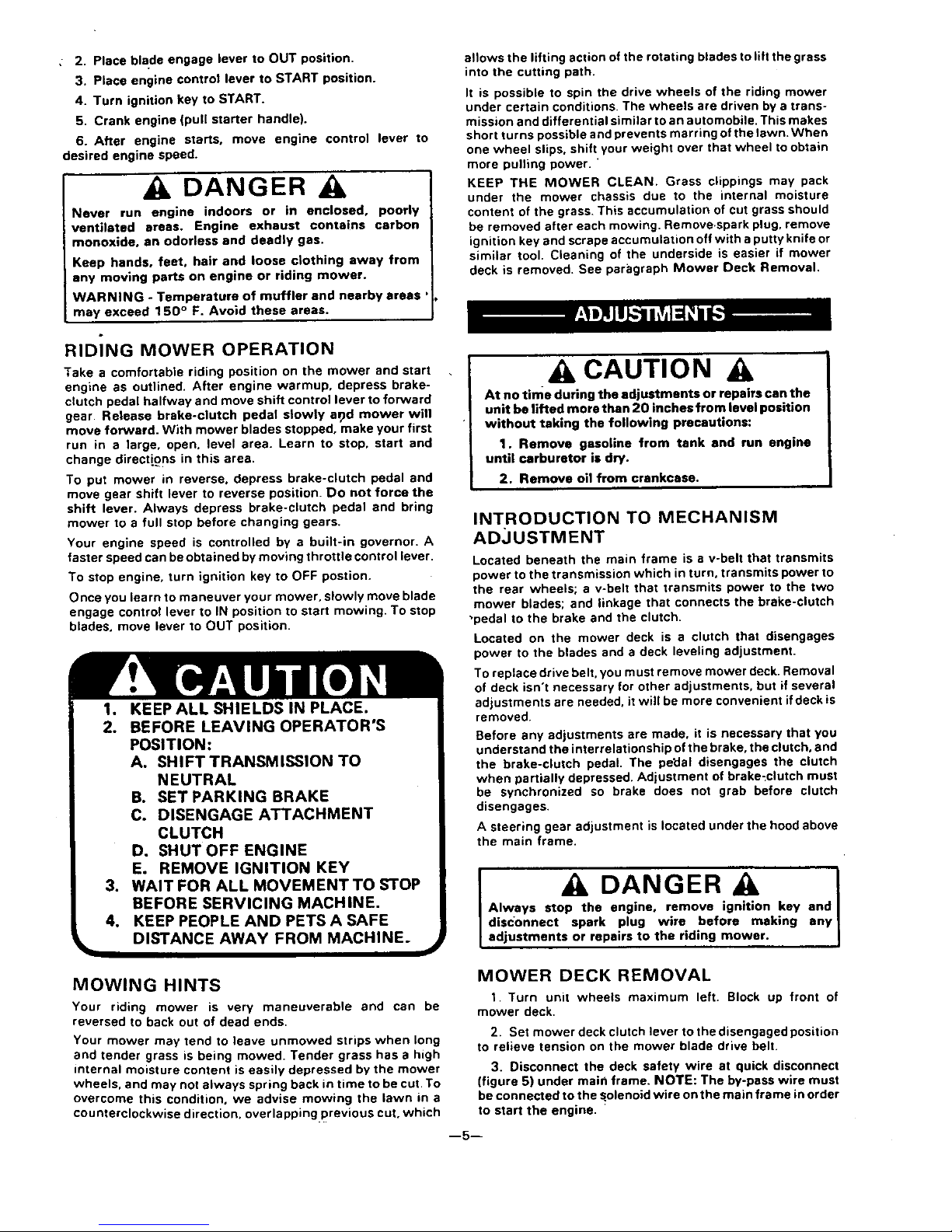
MOWER DECK REMOVAL
1. Turn unit wheels maximum left. Block up front of
mower deck.
2. Set mower deck clutch lever to the disengaged position
to relieve tension on the mower blade drive belt.
3. Disconnect the deck safety wire at quick disconnect
(figure 5) under main frame. NOTE: The by-pass wire must
be connected to the solenoid wire on the main frame in order
to start the engine.
--5--
BELT GUIDES
ENGINE
BY'PASS
WlHE
QUICK
"AR DECK GUIDE BRACKE'I
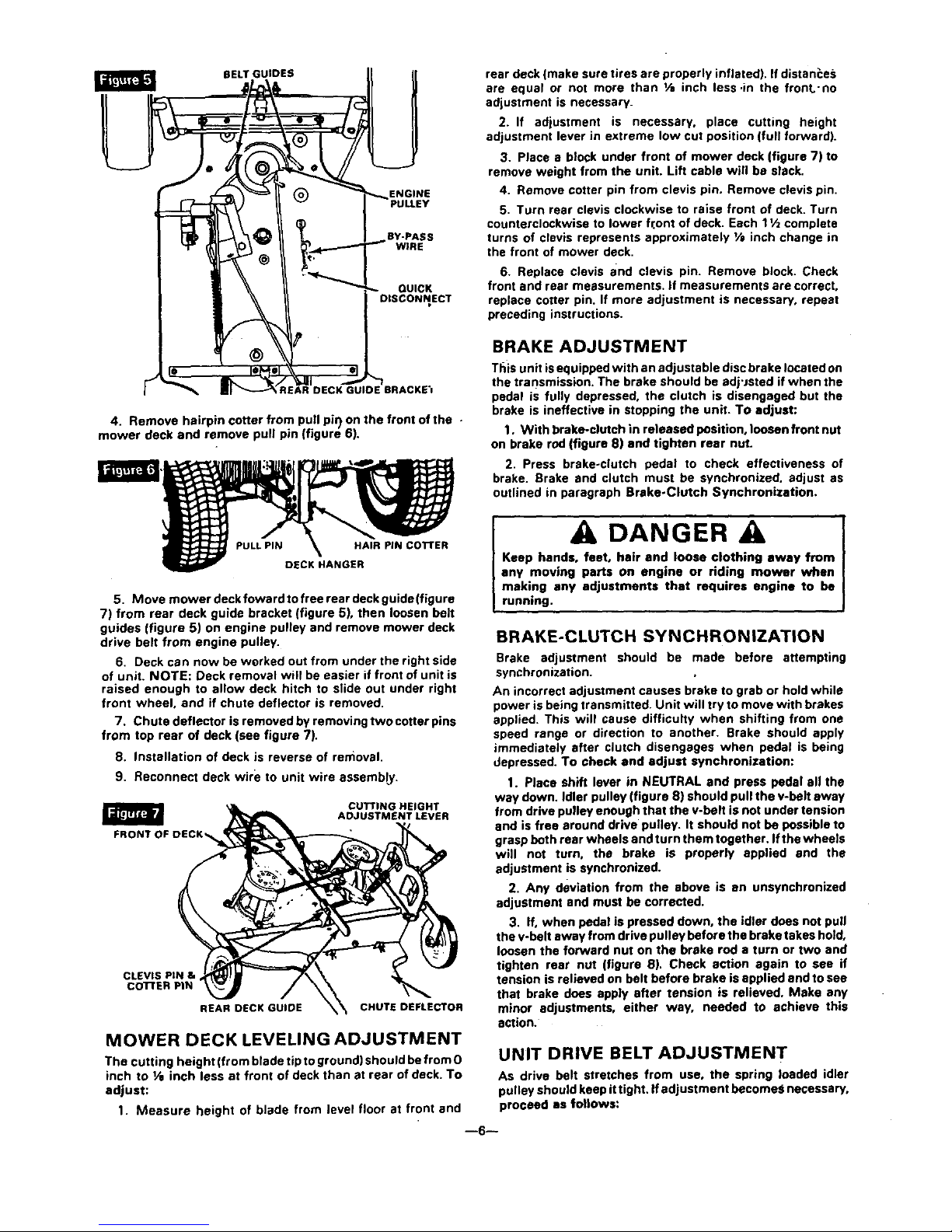
4. Remove hairpin cotter from pull pil) on the front of the -
mower deck and remove pull pin (figure 6).
5. Move mower deckfowardtofreerear deckguide(figure
7) from rear deck guide bracket (figure 5), then loosen belt
guides (figure 5) on engine pulley and remove mower deck
drive belt from engine pulley.
6. Deck can now be worked out from under the right side
of unit. NOTE: Deck removal wilt be easier if front of unit is
raised enough to allow deck hitch to slide out under right
front wheel, and if chute deflector is removed.
7. Chute deflector is removed by removing two cotter pins
from top rear of deck (see figure 7).
8. Installation of deck is reverse of removal.
9. Reconnect deck wire to unit wire assemb_.
CUTTING HEIGHT
ADJUSTMENT LEVER
_A
CLEVIS PIN &
co'n'ER PIN
REAR DECK GUIDE
CHUTE DEFLECTOR
MOWER DECK LEVELING ADJUSTMENT
The cutting height (from blade tip to ground) should be from 0
inch to V, inch less at front of deck than st rear of deck. To
adjust:
1. Measure height of blade from level floor at front and
rear deck (make sure tires are properly inflated). If dlstan_:e_;
are equal or not more than I/a inch less .in the front'no
adjustment is necessary.
2. If adjustment is necessary, place cutting height
adjustment lever in extreme low cut position (full forward).
3. Place a block under front of mower deck (figure 7) to
remove weight from the unit. Lift cable will be slack.
4. Remove cotter pin from clevis pin. Remove clevis pin.
5. Turn rear clevis clockwise to raise front of deck. Turn
counterclockwise to lower fr.ont of deck. Each 11/z complete
turns of clevis represents approximately VB inch change in
the front of mower deck.
6. Replace clevis and clevis pin. Remove block. Check
front and rear measurements, if measurements are correct,
replace cotter pin. If more adjustment is necessary, repeat
preceding instructions.
BRAKE ADJUSTMENT
This unit isequipped with an adjustable disc brake located on
the transmission. The brake should be adj'Jsted if when the
pedal is fully depressed, the clutch is disengaged but the
brake is ineffective in stopping the unit. To adjust:
1. With brake-clutch in released position, loosen front nut
on brake rod (figure 8) and tighten rear nut.
2. Press brake-clutch pedal to check effectiveness of
brake. Brake and clutch must be synchronized, adjust as
outlined in paragraph Brake-Clutch Synchronization.
DANGER A
Keep hands, feet, hair and loose clothing away from
any moving parts on engine or riding mower when
making any adjustments that requires engine to be
running.
BRAKE-CLUTCH SYNCHRONIZATION
Brake adjustment should be made before attempting
synchronization.
An incorrect adjustment causes brake to grab or hold while
power is being transmitted. Unit will try to move with brakes
applied. This will cause difficulty when shifting from one
speed range or direction to another. Brake should apply
immediately after clutch disengages when pedal is being
depressed. To check and adjust synchronization:
1. Place shift lever in NEUTRAL and press pedal all the
way down. Idler pulley (figure 8) should pull the v-belt away
from drive pulley enough that the v-belt is not under tension
and is free around drive pulley. It should not be possible to
grasp both rear wheels and turn them together. Ifthe wheels
will not turn, the brake is properly applied and the
adjustment is synchronized.
2. Any deviation from the above is an unsynchronized
adjustment and must be corrected.
3. If, when pedal is pressed down, the idler does not pull
the v-belt away from drive pulley before the brake takes hold,
loosen the forward nut on the brake rod a turn or two and
tighten rear nut (figure 8). Check action again to see if
tension is relieved on belt before brake is applied and to see
that brake does apply after tension is relieved. Make any
minor adjustments, either way, needed to achieve this
action.
UNIT DRIVE BELT ADJUSTMENT
As drive belt stretches from use, the spring loaded idler
pulley should keep it tight. If adjustment becomes necessary,
proceed as follows:
--6--
 Loading...