


http://www.tecsystem.it
T2612
T2612-B
T2612-C
T2612-AD
INSTRUCTION MANUAL
TECSYSTEM S.r.l.
20094 Corsico (MI)
Tel.: +39-024581861
Fax: +39-0248600783
T2612 UNI
TECSYSTEM S.r.l ®
R. 1.3 07/09/12

2
T2612 UNI
TECSYSTEM S.r.l ®
POWER SUPPLY
• Rated voltage 120 or 240 Vac 50/60 Hz
• Selection through voltage jumper
• Tolerance +/- 10%
• Power input protected by 500 mA fast
fuse
COMMUNICATION:
ONLY FOR T2612 AND T2612AD
• Standard serial output RS485 Modbus®
RTU
ANALOGUE OUT:
ONLY FOR T2612C AND T2612AD
• 1 output 4-20 mA ref. 0-240°C
INPUTS
• 4 inputs RTD Pt100 sensors - 3 wires
• 4th additional input (selectable)
• Removable rear terminals
• Input channels protected against electri-
cal and magnetic noises and spikes
• Sensors length cables compensation up
to 500 m (1mm²)
OUTPUTS
• 2 alarm relays (ALARM-TRIP)
• Output contacts capacity of ALARM, TRIP,
FAULT relays: 5A 220Vac cosφ=1
• Fan 1 and Fan 2 outputs protected by separate 10A slow fuses (max 16A)
• Output contacts capacity of FAN relays: 20A
220Vac cosφ=1
TEST AND PERFORMANCES
• Assembling in accordance with CE rules
• Protection against electrical and mag-
netic noises CEI-EN61000-4-4
• Dielectric strength: 2500 Vac for 1 minute from relays to sensors, relays to
power supply, power supply to sensors
• Accuracy: ± 1% full scale, ± 1 digit
• Ambient operating temperature: -20°C to
60°C
• Humidity: 90% non-condensing
• Housing: painted steel panel, frontal part
in polycarbonate IP65
• Burden 7VA
• Data storage 10 years minimum
• Digital linearity of sensors signal
• Self-diagnostic circuit
• Program and reading resolution: 1 digit
• Opt. Protection treatment of electronic
part
DISPLAYING AND DATA MANAGEMENT
• 1 display 20.5 mm high with 3 digits for displaying temperatures
• LED for displaying reference channel
• LED’s indicating alarm or trip channel
• LED indicating FAULT
• Temperature monitoring from 0°C to 240 °C
• 2 alarm thresholds for channels 1-2-3
• 2 alarm thresholds for channel 4
• 2 alarm ON-OFF thresholds for fan control
• Manually operated fans
• Sensors diagnostic (Fcc-Foc-Fcd)
• Entering the programming by frontal push
button
• Automatic stop of programming cycle after 1
minute of no operation
• Wrong programming automatic display
• Possibility of setting automatic channel
scanning, hottest channel, manual scanning
• Maximum temperatures and alarms storage
• Frontal alarm reset key
• Possibility of setting HOLD function for out-
put relays
DIMENSIONS
• Frontal panel: 320mm x 210mm
• Depth 90mm
1) TECHNICAL SPECIFICATIONS

3
T2612 UNI
TECSYSTEM S.r.l ®
2) MOUNTING
Make a hole with the dimensions of 155 x 280 mm (See cut-out diagram at page 13)
3) POWER SUPPLY
Select the power voltage (120 or 240 VAC) through the “Voltage change” jumper.
REMARK: In case of unit replacement, to grant the correct and safe operating, you
must replace the sensors, relays, and power supply connecting terminals with the
new terminals provided with the unit: this only if the terminal blocks are of different
brand.
4) ALARMS AND FAN CONTROL ELECTRICAL CONNECTIONS
Take the removable terminal board off the unit before wiring.
ALARM and TRIP relays energize only when the prefixed temperature limits are reached.
The FAULT relay always energizes when the apparatus is powered and it resets when the
Pt100’s are damaged or when there is no power voltage.
The FAN relays can be used for fan control or else they can be included in the conditioning
circuit of the transformer box.
5) THERMOMETRIC SENSORS CONNECTION
Each Pt100 sensor has three conductors : one white and two red (CEI 75.8)
Fig.1 shows the disposition in the terminal board of the connection cables to the unit.
Channel 2 must be always referred to the central column of the transformer.
Channel 4 must be always referred to the ambient Pt100 sensor, if you want to monitor the
temperature of the transformer box through the T2612 unit.
6) PT100 EXTENSION CABLE: TECHNICAL SPECIFICATIONS
Cable 20xAWG 20/19 Cu/Sn
Section 0.55 mm²
Flame retardant Insulation PVC105
In accordance with CEI 20.35 IEC 332.1
Max working temperature: 90°C
Conformation : 4 terns of twisted and coloured conductors
Shield Cu/Sn
PVC flame retardant protection covering
External diameter 12.0 mm
Skeins of 100 m
In order to protect the electronic apparatus, we recommend the application of the
insulation transformer 240VAC/240VAC or 120VAC/120VAC.

4
T2612 UNI
TECSYSTEM S.r.l ®
7) MEASURE SIGNALS TRANSPORT
All the transport cables of the Pt100 measure signals must absolutely:
• be divided from the power ones
• be realized with shielded cable with twisted conductors
• have a section of min 0.5 mm²
• be twisted if you have no shield
• be firmly fixed in the terminal board
• have tinned or silvered conductors
All the “T” series units have the sensors linearization with a max error of 1% v.f.s..
8) THERMOMETRIC SENSORS DIAGNOSTIC
In the event one of the thermometric sensors installed on the machine to protect is damaged, the FAULT relay energizes immediately, the ALARM and TRIP LED’s of the dam-
aged channel lighten and the FAULT LED is lightening.
The screen will automatically display a message showing the fault condition:
• Fcc sensor is short circuited
• Foc sensor is open
9) FCD FUNCTION - DEFECTIVE SENSORS
During the unit normal operation, if the Fcd-YES function has been selected, the display will
show Fcd indicating that a sensor is damaged and the LED corresponding to the affected
channel will lighten.
The FAULT relay will energize giving a signal to the operator.
After the replacement of the damaged sensor, you can reset the alarm pushing RESET until
the display shows the message rSt.
10) TEMPERATURES DIAGNOSTIC
When one of the thermometric sensors surveys a temperature exceeding by 1°C the alarm
limit, after 4 seconds the ALARM relay will energize and the ALARM LED of the affected
channel will switch on.
The same occurs when the TRIP temperature limit is detected: the TRIP relay energizes
and the TRIP LED corresponding to the affected channel is lightening.
When the surveyed temperature declines of 1°C below the prefixed limit for the ALARM and
TRIP switching , the relays de-energize and the respective LED’s switch off.
TECSYSTEM srl has realised a special cable for the measure signal transport
with all the protection requirements according to CEI Norms: mod. CT-ES

5
T2612 UNI
TECSYSTEM S.r.l ®
11) COOLING-FAN CONTROL
The T2612 unit, if suitably programmed, can control the ON/OFF of the transformer fans
according to the set temperature values.
The fans of the machine can be controlled in two different ways:
• using the temperatures surveyed by the sensors on the three columns
CHF 1 2 3 - CH4 excluded
ALARM and TRIP LED 1.2.3 illuminated (e.g. F1: ON at 80°C - OFF at 70°C)
(e.g. F2: ON at 90°C - OFF at 79°C)
• by an additional sensor (CH4-YES) for the ambient temperature inside the transformer
box.
CHF 4
ALARM e TRIP LED Ch4 illuminated (e.g. F1: ON at 40°C - OFF at 30°C)
(e.g. F2: ON at 45°C - OFF at 35°C)
Press
▲ and ▼ key to select this function.
It is possible to operate the fans manually by pushing the AUTO/ON key.
12) FAN TEST
It is possible, through programming (HFn), to lay down that fans are activated for 5 minutes
each “xxx” hours, regardless of column or room temperature values (ex.: with HFn=001 fans
are activated for 5 minutes each hour; Maximum value: 240).
This function has the aim to periodically verify the working of the fans and their control apparatus during long idle periods.
Loading 000 value, this function is inhibited.
13) HOLD FUNCTION
To select the hold function choose the program option HLD-Yes. With hold function enabled, when temperature exceeds the alarm set point value, the alarm relays will energize
and the alarm LED’s will illuminate until you reset the relay contacts in manual reset mode.
Reset is only possible when temperature falls below the set point value. To exclude the hold
function select the program option HLD-no.
14) DISPLAY MODE
By pressing DISPLAY MODE you can select one of the three display modes:
• HOT : the display shows automatically the temperature of the hottest channel
• MAN : each channel may be viewed manually by pressing the
▲ or ▼ key.
• T.MAX: the unit shows the max. temperature recorded by the sensors and any alarm
recorded after the last reset. To check the channels press
▲ or ▼ key.
• SCAN : channels cyclically change every 2 seconds

6
T2612 UNI
TECSYSTEM S.r.l ®
15) WORKING PROGRAM CONTROL
To review the entered values momentarily press PRG key, “viS” appears and continue to do
so advancing to each programmed value. Press ENT to return to normal operating mode.
16) LAMP TEST
It is advisable to carry out this test on a regular basis to ensure all lamps are functioning
normally. Pressing the TEST key at any time allows the user to test all lamps, initially all
LED’s illuminate.
17) ALARM RELAYS TEST
All relays may be tested using the following procedure.
Press and hold the TEST key for 5 seconds, changing to the main screen display tSt appear.
Release the test key when the yellow relay test LED TEST ON illuminates.
The first relay to test will be indicated with the LED flashing.
The relays to test are the following, in sequence:
• “Flt” : RTD fault relay
• “Fan 1” : 1st cooling relay
• “Fan 2” : 2nd cooling relay
• “Alr” : alarm relay
• “trP” : trip relay
Use the Scroll
▲ or ▼ keys to make the selection. Press the SET key to perform the test on
the selected relay. To reset press the RESET key and will appear ON and OFF on display.
To discontinue operation and revert to normal operation, press the TEST key.
At the start of the test, a timer is automatically initiated which reverts the unit to normal
operation if no inputs are detected for a period of five minutes.
18) ALARM RELAY EXCLUSION
If you want to exclude the ALARM signal press RESET key: relay de-energises itself and
LED ALARM, which was fixed, will start to blink. If the transformer temperature goes up to
TRIP temperature - 5°C, the relay ALARM
Exclusion system is automatically disconnected when the temperature goes under the
ALARM threshold.
19) BUZZER
T2612 unit includes a buzzer that is operating when any alarm status occurs, except for Fan
1 and Fan 2 outputs
By pushing the TEST/MUTE key you can stop the buzzer.
If any lamp is not functioning the unit must be returned for repair.

7
T2612 UNI
TECSYSTEM S.r.l ®
N° KEYS EFFECT NOTES
1 PRG/SET
Keep pressed PRG key until PRG-ON led turns on.
After PRG indication,
it appears ALARM threshold for CH U-V-W
Program LED will light
2 Enter the desired Alarm setpoint
3 PRG/SET TRIP set T° appears
4 Enter the desired Trip setpoint
5 PRG/SET Led CH 4 blinks Enabling CH 4
6 Load YES or NO
YES: CH 4 connected
NO: CH 4 disconnected
11 PRG/SET
Led Fan blinks and channel leds
o which fan is referred turn on
12 Select NO, CH U-V-W or CH 4 (if CH 4 YES)
NO: disabled fan,
Goes to point 21
13 PRG/SET Display shows ON FAN1 turning on
14 PRG/SET It appears ON threshold for FAN1
15 Load desired threshold
16 PRG/SET Display shows OFF FAN1 turning off
17 PRG/SET It appears OFF threshold for FAN1
18 Load desired threshold
to set up FAN2 repeat the same procedure as FAN1
19 PRG/SET Display shows HFn
Fan cyclic test for 5 minutes each
“n” hours
20 Load desired number of hours 000= disabled function
21 PRG/SET Fcd appears on display
22 Enter Fcd YES or NO
Fcd YES= control of damaged
Pt100 connected
23 PRG/SET Hld appears on display HLd YES = HOLD feature enabled
24 Enter HLd YES or NO
25 PRG/SET PRG appears on display
Prg NO= program cannot be
changed
26 set up Prg YES or NO
27 PRG/SET
Adr appears on display
ONLY for T2612 and T2612-AD,
not for T2612-B and T2612-C
28
enter the address of the unit
29 PRG/SET
on display appears bdr
30
enter the desired Baud rate
Possible Baud rates:
2.4k-4.8K-9.6K-19.2K
(8 bit, Stop=1 cannot be changed)
31 PRG/SET
Par appears on display Parity bit setting
32
enter the desired Parity bit
No= not parity bit
Odd= Odd parity bit
Eve= Even parity bit
33 PRG/SET Display shows END Programming end
34 ENT Loaded data storage and programming exit
Err: wrong programming for
values indicated by leds (note 2)
35
ENT
PRG/SET
Programming is completed.
Press ENT to return to normal operating mode
The unit will perform
the light test
7 PRG/SET CH4 Alarm setpoint appears
8 Enter the desired Alarm setpoint
9 PRG/SET CH4 Trip setpoint appears
10 Enter the desired Trip setpoint
20) PROGRAMMING

8
T2612 UNI
TECSYSTEM S.r.l ®
21) PROGRAMMING REHABILITATION IN CASE OF BLOCK (Prg no)
In the event program access is blocked the display will show SET and then display “noP”.
To gain access, press the ENT key and return to normal operation. Touch the PRG key and
then, press and hold the TEST key for approximately 7 seconds until the flashing PRG
screen display ends.
NOTE: this procedure removes the lockout feature. To block access again, this feature must
be reprogrammed.
22) RULES FOR WARRANTY
The Product purchased is covered by manufacturer's warranty or the seller's terms and conditions set forth in the "General Conditions of Sale Tecsystem srl", available at
www.tecsystem.it and / or purchase agreement.
The warranty is considered valid only when the product will be damaged by causes attributable to TECSYSTEM srl, such as manufacturing or components defects.
The warranty is invalid if the Product proves tampered / modified, incorrectly connected,
because voltages outside the limits, non-compliance with the technical data for use and assembly, as described in this instruction manual.
Any action about warranty is always at our factory in Corsico-MI, Italy as stated by the
" General Conditions of Sale Tecsystem srl ".
RAEE: This SYMBOL, shown on the unit, indicates that the waste must be subject to
"separate collection”. The end-user must send the unit to the “waste collection centers”,
or return the unit to the dealer against the purchase of a new equivalent device.
23) IMPORTANT NOTICE
Before conducting the insulation test, disconnect the power supply to the unit to avoid damage.
24) 4-20 mA OUTPUT CONNECTION (ONLY FOR MODEL T2612C AND T2612AD)
To 4-20 mA output can be connected a read-out or acquisition device.
The admitted load impedance for each output goes from 0 to 500 ohm.
4-20 mA signal is referred to 0-240°C range with accuracy of 1% with respect to full scale
value.
For 0-240 range, the relation current/temperature is the following:
I
out
= (T/15)+4 (T= temperature in °C)
PROGRAMMED DATA DIAGNOSTIC
In case of breaking of the internal storage or corruption of programmed data, just after
switching on it appears Ech indication with the relevant reporting of the Fault contact.
In this case, for safety reasons, the default parameters: Alarm Ch1-2-3= 90°C, Trip Ch1-23= 119°C, Ch4= NO, Ch-Fan= 1-2-3, Fan-on= 70°, Fan-off= 60°, HFn= 000 are automatically reloaded.
Eliminate Ech indication by pressing RESET and run programming to insert desired values.
Finally turn off and turn on again the unit to verify the correct memory working; in case it is

9
T2612 UNI
TECSYSTEM S.r.l ®
TROUBLESHOOTING
PROBLEMS
CAUSES / SOLUTIONS
The unit will not switch on,
with control power energized.
Check the terminal block for correct installation.
Check for voltage at the terminal block.
Channel 4 is indicating fault and displaying
FOC.
Only three Pt100 sensors are connected.
Wrong programming of the unit.
Repeat programming.
One of the 4 channels is indicating fault
and displaying FOC/FCC
Check the sensors connection.
Look for damaged sensors.
Replace damaged sensor.
When switching the unit on-off, the alarm
and trip relays energize.
Strong electrical noise is being picked up
on the power line.
Check to ensure the shield of the sensor
cable is connected to the panel ground.
Install shielded cable (Mod. CT-ES) or
twist the sensor conductors.
All the sensors are displaying FCC.
Wrong wiring connections.
The terminal block is upside-down.
The temperature indicated by one or more
channels is wrong.
The sensors are defective.
Check the sensor resistance with an Ohmmeter.
The unit is calibrated incorrectly.
Return for repair.
Sudden activation of the trip relay with
normal operating temperature.
One channel caused the occurrence.
Sensor defective (Fcd).
Replace the sensor.

10
T2612 UNI
TECSYSTEM S.r.l ®
25) MODBUS RS485 INTRODUCTION (ONLY FOR MODEL T2612 AND T2612AD)
The T2612 implements a sub-whole of the standard serial communication protocol Modicon
Modbus RTU. The Modbus T2612 employs a RS485 connection with 2 twisted-pair wire
hardware; with this mode it is allowed to connect up to 32 monitoring units on the same
wiring. The T2612 is always in slave mode.
26) ELECTRICAL CONNECTION
The twisted-pair wiring that connects all the units with RS485 needs 120 ohm terminal resistors on the opposite side of the master. To enable the terminal resistor connect the “END”
terminal with the “TX” terminal (-) on the “serial output” terminal board.
Important Note : the twisted-pair wires must be connected according to the polarity;
then, all the (+) with the (+) and all the (-) with the (-).
As far as the signal cable to be used to guarantee a correct working of the network is concerned, we suggest to follow what is provided for by EIA RS485 standard which advises the
use of a 24AWG loop.
In order not to affect the line impedance, connect the loop keeping into consideration the
polarities and lay the network avoiding to create sharp bends or ring windings.
In case of necessity, it is also available the GND dead ground terminal.
27) DATA FRAME
The asynchronous transmission frame is made of 1 bit of START, 8 bit Data, 1 bit of parity
(if enabled) and 1 bit of Stop.
The allowed Baud rates are: 2400, 4800, 9600 and 19200; the addresses are from 0 to 32
(0 for non-connected).
The DATA are “16bit” length where no specified.
28) DATA PACKET
A complete question/answer sequence is as follows :
Question from the master :
SLAVE ADDRESS - 1byte
FUNCTION CODE - 1byte
DATA - variable, it depends on the function code
CRC - 2 bytes
Answer from slave :
SLAVE ADDRESS - 1byte
FUNCTION CODE - 1byte
DATA - variable, it depends on the function code
CRC - 2 bytes

11
T2612 UNI
TECSYSTEM S.r.l ®
29) FUNCTION CODE
READING DATA OF SET POINT AND TEMPERATURE REGISTERS: CODE 3
(10)
Question :
Slave addr, 3
(10)
,Starting address Hi, Starting address Lo, Number of points Hi, Number of
points Lo
CRC-Hi, CRC-Lo
Answer:
Slave addr, 3
(10)
, Byte count, Data Hi, Data Lo... , CRC-Hi, CRC-Lo
EXCEPTION CODE:
Exception responses
In case of wrong questions, the T2612 answers with modified codes and codified errors according to the following:
Packet of error answer :
Slave address, Function code (+bit 7 to 1), Exception code, CRC-Hi, CRC-Lo
1 - Function code not present
2 - Wrong data address
3 - Wrong data (i.e. length)
WRITING DATA : CODE 16
(10)
Writing questions:
Slave addr, 16
(10)
,Starting address Hi, Starting address Lo, Number of registers Hi, Number
of registers Lo,
Byte count, Data Hi, Data Lo, ..... , CRC Hi, CRC Lo
Writing answer:
Slave addr, 16
(10)
,Starting address Hi, Starting address Lo, Number of registers Hi, Number
of registers Lo,
CRC-Hi, CRC-Lo
30) HOLDING REGISTER AND INPUT REGISTER ADDRESSES (in decimals):
Addr.
(10)
Hi-Lo DataHi DataLo
———————————————————————————————————————
00-00 00 ALARM SET POINT |>Absolute data from 0-240
(10)
=0-240°C
00-01 00 TRIP SET POINT |>
00-02 00 ALARM CH4 SET POINT |>
00-03 00 TRIP CH4 SET POINT |>
00-04 00 FAN ON SET POINT |>
00-05 00 FAN OFF SET POINT |>
00-06 00 FAN2 ON SET POINT |>
00-07 00 FAN2 OFF SET POINT |>
———————————————————————————————————————

12
T2612 UNI
TECSYSTEM S.r.l ®
————————————————————————————————————————
00-08 00 TEMP CH1 |> Temp. with offset 10
(10)
(range 0-240)
|> 11=1°C, 10=0°C, 9=-1°C,etc.
00-09 00 TEMP CH2 |>
00-10 00 TEMP CH3 |>
Temp. with offset 50
(10)
(range –40/+200)
|> 51=1°C, 50=0°C, 49=-1°C,etc.
|> Special values for error Pt100:
00-11 00 TEMP CH4 |> (see the instruction T935)
00-12 00 TEMP. MAX CH1 |> 0
(10)
= Fcc
00-13 00 TEMP. MAX CH2 |> 1
(10)
= Foc
00-14 00 TEMP. MAX CH3 |> 2
(10)
= Fcd
00-15 00 TEMP. MAX CH4 |>
————————————————————————————————————————–
00-16 00 H.FAN (max cycling interval for test fan operation)
00-17 00 RL-STATUS : relays (1=ON): bit 0 -> Alarm, 1 -> Trip, 2 -> Fault,
3 -> Fan1, 4 -> Fan2
00-18 00 Status prog. : bit 0-> Fan Y/n, bit 1-> Fan2 Y/n, bit 2-> Ch4 Y/n,
bit 3-> Fan CH4, bit 4-> Hold Y/n, bit 5-> Fcd Y/n,
bit 6->Prg Lock Y/n
00-19 00 Alarm memory :
bit 7 6 5 4 3 2 1 0
CH4 CH3 CH2 CH1 CH4 CH3 CH2 CH1
—————–TRIP——————— ——————ALARM——————
31) CRC CALCULATION
This protocol includes 2 byte CRC-16 in all the transmission. The typical polynomial
(11000000000000101B) is used for the calculation and the result is “hanged up” at the end
of the packet. The polynomial is used in reverse order with the more significant bit eliminated because useless for the calculation.
32) PARAMETERS DESCRIPTION
A - 16bit register
AL - A lower part
AH - A upper part
i,j, - COUNTERS
(+) - EXCLUSIVE OR
Di - frame datum (thousandth) of the packet
N - byte number of the packet, excluded the 2 of CRC
G - Polynomial : 1010-0000-0000-0001
shr - shift to the right
33) ALGORITHM
1) 0xFFFF -> A
2) 0 -> i
3) 0 -> j
4) Di (+) AL -> AL
5) j +1 -> j
6) shr A
7) if carry then G (+) A -> A
8) if NOT j=8 then go to 5
9) i +1 -> i
10) if NOT i = N then go to 3
11) A -> in CRC (the result is in the L,H)

13
T2612 UNI
TECSYSTEM S.r.l ®
CUTOUT
GALVANIZED SHEET IRON
Thickness 1.2 mm
FRONT VIE
W
Cut out: 155 X 280 mm
Screw rivet M3 x 15mm
Screw rive t
M3 x 15mm
Screw rive t
M3 x 15mm
190 mm
210 mm
150 mm 150 mm
320 mm
Screw rivet
M3 x 15mm
Screw rivet
M3 x 15mm
Screw rivet M 3 x 15mm
14
T2612 UNI
TECSYSTEM S.r.l ®
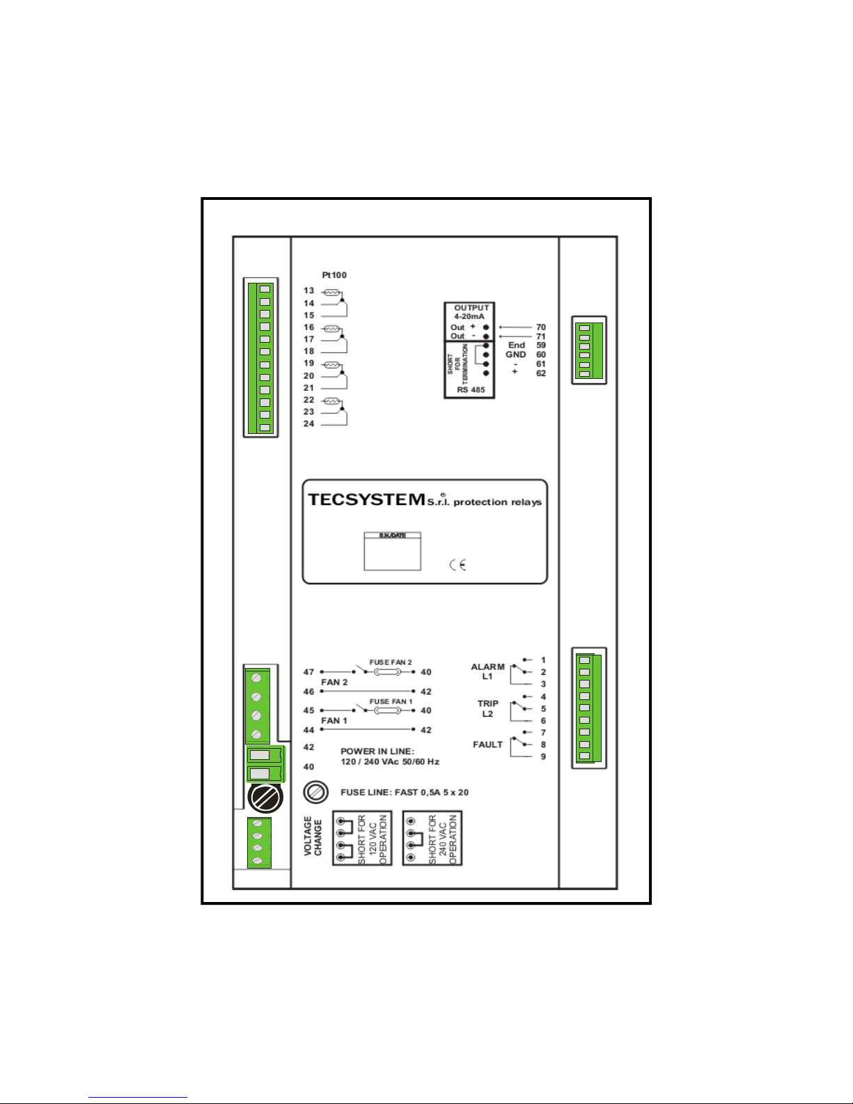
T2612 REAR CONNECTIONS
CH4
CH3 CH2 CH1

15
T2612 UNI
TECSYSTEM S.r.l ®
T2612 FRONT PANEL

16
T2612 UNI
TECSYSTEM S.r.l ®
NOTES:
 Loading...