

TECSYSTEM T154 Series Instruction Manual
1MN0044 REV. 0
operates with ISO9001:2008 certified quality system
http: //www.tecsystem.it
R. 1.0 05/09/13
“Translations of the original instructions”
TECSYSTEM S.r.l.
20094 Corsico (MI)
Tel.: +39-024581861
Fax: +39-0248600783
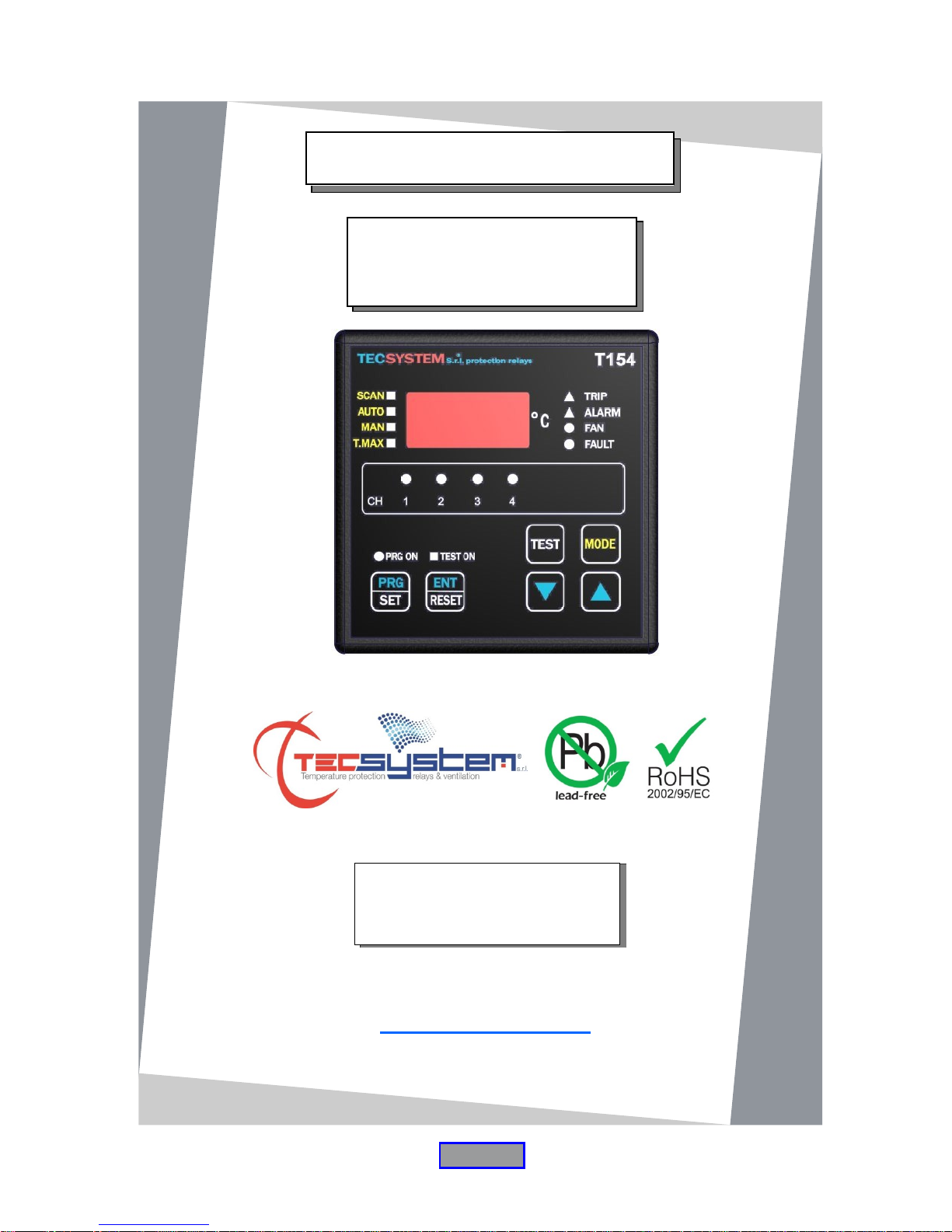
T154 SERIES
INSTRUCTION MANUAL

2
T154 SERIES
First of all we wish to thank you for choosing to use a TECSYSTEM product and recommend you read this instruction
manual carefully: You will understand the use of the equipment and therefore be able to take advantage of all its
functions.
ATTENTION! THIS MANUAL IS VALID AND COMPLETE FOR THE T154, T154 UL, T154 FAHRENHEIT, T154 -4 E
T154 –4 FAHRENHEIT VERSIONS OF THE T154 SERIES.
PAGE
1) SAFETY REQUIREMENTS
…………………………………..
3
2) ACCESSORIES
…………………………………..
4
3) TECHNICAL SPECIFICATIONS
…………………………………..
5
4) FRONT PANEL
…………………………………..
7
DISPLAY
…………………………………..
8
CHECKING THE WORK PROGRAM
…………………………………..
—
LED TEST
…………………………………..
—
ALARM RELAY TEST
…………………………………..
—
ALARM RELAY SILENCING
…………………………………..
—
5) INSTALLATION
…………………………………..
9
6) ELECTRICAL CONNECTIONS
…………………………………..
10
T154 BACK
…………………………………..
—
POWER SUPPLY
…………………………………..
11
ALARMS AND VENTILATION
…………………………………..
—
TEMPERATURE SENSORS
…………………………………..
—
7) PROGRAMMING
…………………………………..
12
T154 /UL/ T154 FAHRENHEIT
…………………………………..
12
T154 –4 / T154 –4 FAHRENHEIT
…………………………………..
14
MEASUREMENT SIGNAL TRANSFER
…………………………………..
16
TEMPERATURE SENSOR DIAGNOSTICS
…………………………………..
—
PROGRAMMED DATA DIAGNOSTICS
…………………………………..
17
TEMPERATURE DIAGNOSTICS
…………………………………..
—
COOLING FAN CONTROL
…………………………………..
—
FAN TEST
…………………………………..
—
10) TECHNICAL SPECIFICATIONS OF THE EXTENSION CABLE FOR
Pt100 (Ni100 or Ni120)
…………………………………..
18
11) FCD FUNCTION
…………………………………..
—
12) WARRANTY REGULATIONS
…………………………………..
19
13) TROUBLESHOOTING
…………………………………..
—
14) EQUIPMENT DISPOSAL
…………………………………..
—
15) USEFUL CONTACTS
…………………………………..
20
16) UL RATINGS (only CURUS versions)
…………………………………..
—
3
T154 SERIES
ATTENTION:
Read the manual carefully before starting to use the control unit. Keep the instructions for future reference.
Do not open the device, touching any internal components can cause electric shock. Contact with 110-240 Volts
AC can be fatal. To reduce the risk of electric shock, do not dismantle the back of the device for any reason. Moreover its
opening would void the warranty. Before connecting the device to the power supply, make sure that all the
connections are correct. Always disconnect the unit from the supply before any cabling modification.
Any intervention on the equipment must be entrusted to a qualified repair engineer
Failure to comply with these instructions can cause damages, fires or electric shock, and possible serious
injuries!
POWER SUPPLY
The T154 series has UNIVERSAL power supply, i.e. it can be supplied by 24 to 240 Vac-Vdc, irrespectively of polarity in Vdc.
Before using it, make sure the power cable is not damaged, kinked or pinched. Do not tamper with the power cable. Never
disconnect the unit by pulling the cable, avoid touching the pins. Do not carry out any connecting/disconnecting with wet
hands. To disconnect the device, do not use objects such as levers. Immediately disconnect the device if you smell burning
or see any smoke: contact technical service.
LIQUIDS
Do not expose the equipment to splashes or drops, do not position it in places with humidity exceeding 90% and never touch
with wet or humid hands during storms. If any liquid penetrates the control unit, disconnect it immediately and contact
technical service.
CLEANING
Disconnect the power cable before cleaning the control unit, use a dry cloth to dust it, without any solvent or detergents, and
compressed air.
OBJECTS
Never insert any objects into the cracks of the control unit. If this happens, disconnect the control unit and
contact an engineer.
USE RESERVED TO QUALIFIED PERSONNEL
The purchased goods are a sophisticated electronic device that is totally unsuitable to be used by non-qualified personnel.
Any intervention must be carried out by a specialist engineer.
ACCESSORIES
The use of non-original accessories or spare parts might damage the unit and endanger users' safety. In the event of faults,
contact technical service.
LOCATION
Install the control unit indoors, in a place protected from water splashes and sun rays. Do not place near heat sources
exceeding the parameters stated in this manual. Position on a stable surface, far from any possible vibrations. Position the
unit as far as possible from any intense magnetic fields.
REPAIRS
Do not open the control unit. For any fault, always use qualified personnel. The opening of the control unit and/or the removal
of the series identifying label entails the automatic forfeiture of the warranty. The Warranty seal is applied to all devices, any
attempt to open the unit would break the seal and cause the consequent automatic forfeiture of the warranty.
TECHNICAL INFORMATION
Mail: ufficiotecnico@tecsystem.it — tel: 02/4581861
4
T154 SERIES
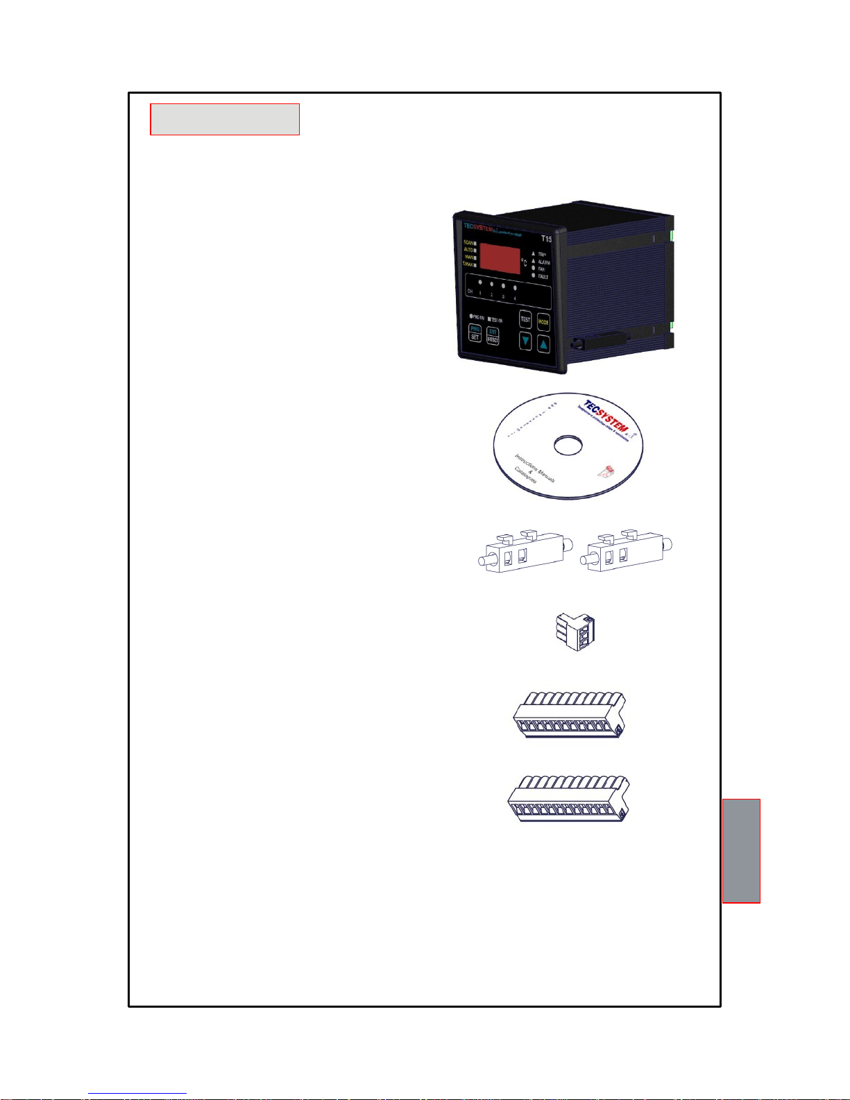
The following objects are present inside the box:
Control unit
Instruction manual CD
2 blocks for panel mounting
1 supply terminal 3 poles pitch 5 Code:
2PL0367
1 relay terminal 11 poles pitch 5
Code: 2PL0359
1 sensor terminal 12 poles pitch
5 Code: 2PL0361
1MN0030 REV. 0
ATTENTION: always install the device using the terminals included in the pack. The use of terminals other
than those included with the control unit might cause malfunctions.

5
T154 SERIES
TECHNICAL
SPECIFICATIONS
T154
T154 UL T154
FAHRENHEI
T
T154 –4
T154 –4
FAHRENHEIT
POWER SUPPLY
Supply rated values
24-240
Vac-Vdc
50/60HZ
24-240
Vac-Vdc
50/60HZ
24-240
Vac-Vdc
50/60HZ
24-240
Vac-Vdc
50/60HZ
24-240
Vac-Vdc
50/60HZ
Supply min/max values
20-270
Vac-Vdc
50/60Hz
20-270
Vac-Vdc
50/60Hz
20-270
Vac-Vdc
50/60Hz
20-270
Vac-Vdc
50/60Hz
20-270
Vac-Vdc
50/60Hz
Vdc with reversible polarities
● ● ● ● ●
INPUTS
4 inputs for RTD sensors, Pt100 type with 3 wires
● ● ● ● ●
Ni100 or Ni120 sensors on request
Option
Option
Option
Option
Option
Connections on extractable terminal blocks
● ● ● ● ●
Input channels protected against electromagnetic
interference
● ● ● ● ●
Cable compensation for thermistors
500 m
(1 mm2)
500 m
(1 mm2)
500 m
(1 mm2)
500 m
(1 mm2)
500 m
(1 mm2)
OUTPUTS
2 alarm relays (ALARM AND TRIP) SPDT
● ● ● ● ●
1 fault sensor or operating failure (FAULT) relay
SPDT
● ● ● ● ●
Output relay with 5A-250Vac-res COS(D=1
contacts.
● ● ● ● ●
Ventilation management relay SPST
● ● ● ● ●
DIMENSIONS
100x100 mm– din43700-depth .131mm
(terminal block included)
Hole 92 x 92
mm
Hole 92 x 92
mm
Hole 92 x 92
mm
Hole 92 x 92
mm
Hole 92 x 92
mm
TEST AND PERFORMANCE
Construction in compliance with CE regulations
● ● ● ● ●
Curus certificate
● ● ● ● ●
Rina certificate
Option
Option
Option
Option
Option

6
T154 SERIES
TECHNICAL
SPECIFICATIONS
T154
T154 UL
T154
FAHRENHEIT
T154 –4
T154 –4
FAHRENHEIT
TEST AND PERFORMANCE
Protection from electrical interference EN 61000-4-4
● ● ● ● ●
Dielectric strength 1500 Vac for one min. between output
relays and sensors, relays and power supply, power supply
and sensors
● ● ● ●
●
Accuracy ±1% full scale value, ±1 digit
● ● ● ● ●
Ambient operating temperature from –20°C to +60°C
● ● ● ● ●
Humidity 90% non-condensing
● ● ● ● ●
Housing NORYL 94 _V0
● ● ● ● ●
Absorption 4VA
● ● ● ● ●
Data storage: 10 years minimum
● ● ● ● ●
Digital linearity of sensor signal
● ● ● ● ●
Self-diagnostic circuit
●
NO NO NO NO
Electronic protection only on customer's
Option
Option
Option
Option
Option
Vibration test IEC 68-2-6 Width ±1 mm from 2Hz to 13.2Hz
Acceleration ±0.7G from 13.2 Hz to 100 Hz
● ● ● ●
●
(*) Seismic test according to IEEE 344-1.987
● ● ● ● ●
DISPLAY AND DATA MANAGEMENT
1 x 13 mm display with 3 digits to display temperatures and
messages.
● ● ● ●
●
4 LEDs to show the selected channel
● ● ● ● ●
4 LEDs to show the alarm status of the selected channel
● ● ● ● ●
Temperature control from 0°C to + 200°C
●
NO
NO
NO
NO
Temperature control from 0°C to + 240°C (32°F-464°F)
Option
● ● ●
●
2 alarm thresholds for channels 1-2-3
● ● ●
NO NO
2 alarm thresholds for channel 4
● ● ●
NO NO
2 ON-OFF thresholds for FAN control
● ● ● ● ●
Individually programmable alarm thresholds for each channel
NO NO NO
●
●
Sensor diagnostics (Fcc-Foc-FCd)
● ● ● ● ●
Data storage diagnostics (Ech)
● ● ● ● ●
Access to programming through front keyboard
● ● ● ● ●
Automatic exit from programming after 1 minute's inactivity
● ● ● ● ●
Incorrect programming warning
● ● ● ● ●
Selection of automatic channel scanning, hottest channel or
● ● ● ● ●
Storage of maximum temperatures reached by channels and
● ● ● ● ●
Front alarm reset button
● ● ● ● ●
 Loading...