

Page 1
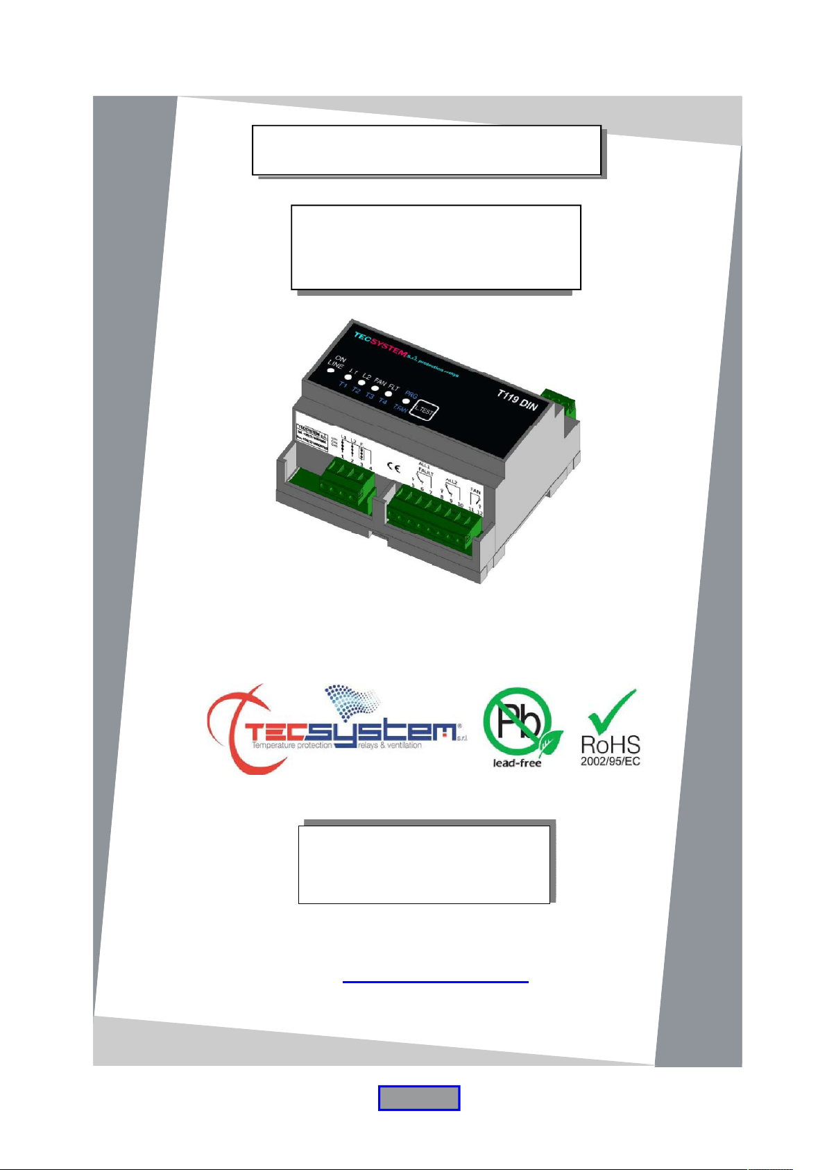
INSTRUCTION MANUAL
T119 DIN
1MN0109 REV. 0
operates with ISO9001:2008 certified quality system
TECSYSTEM S.r.l.
20094 Corsico (MI)
Tel.: +39-024581861
Fax: +39-0248600783
http://www.tecsystem.it
R. 1.0 30/03/15
ENGLISH
Translations of the original instructions
Page 2

INTRODUCTION
First of all we wish to thank you for choosing to use a TECSYSTEM product and recommend you read this instruction
manual carefully: You will understand the use of the equipment and therefore be able to take advantage of all its
functions.
ATTENTION! THIS MANUAL IS VALID AND COMPLETE FOR THE T119 DIN CONTROL UNIT
CONTENTS
1) SAFETY REQUIREMENTS
2) ACCESSORIES
3) TECHNICAL SPECIFICATIONS
4) INTRODUCTION
5) FRONT
POWER SUPPLY
6) PROGRAMMING
ALARM RELAY TEST
LED TEST
ALARM 1 RELAY OPERATION
ALARM 2 RELAY OPERATION
FAN RELAY OPERATION
(VENTILATION)
DELAYED VENTILATION CYCLE (DELAY ON)
SENSOR DIAGNOSTIC DEVICE
PTC SENSOR FAULT
PTC SENSOR FAULT DIAGNOSIS
"PTC" TYPE TEMPERATURE SENSORS
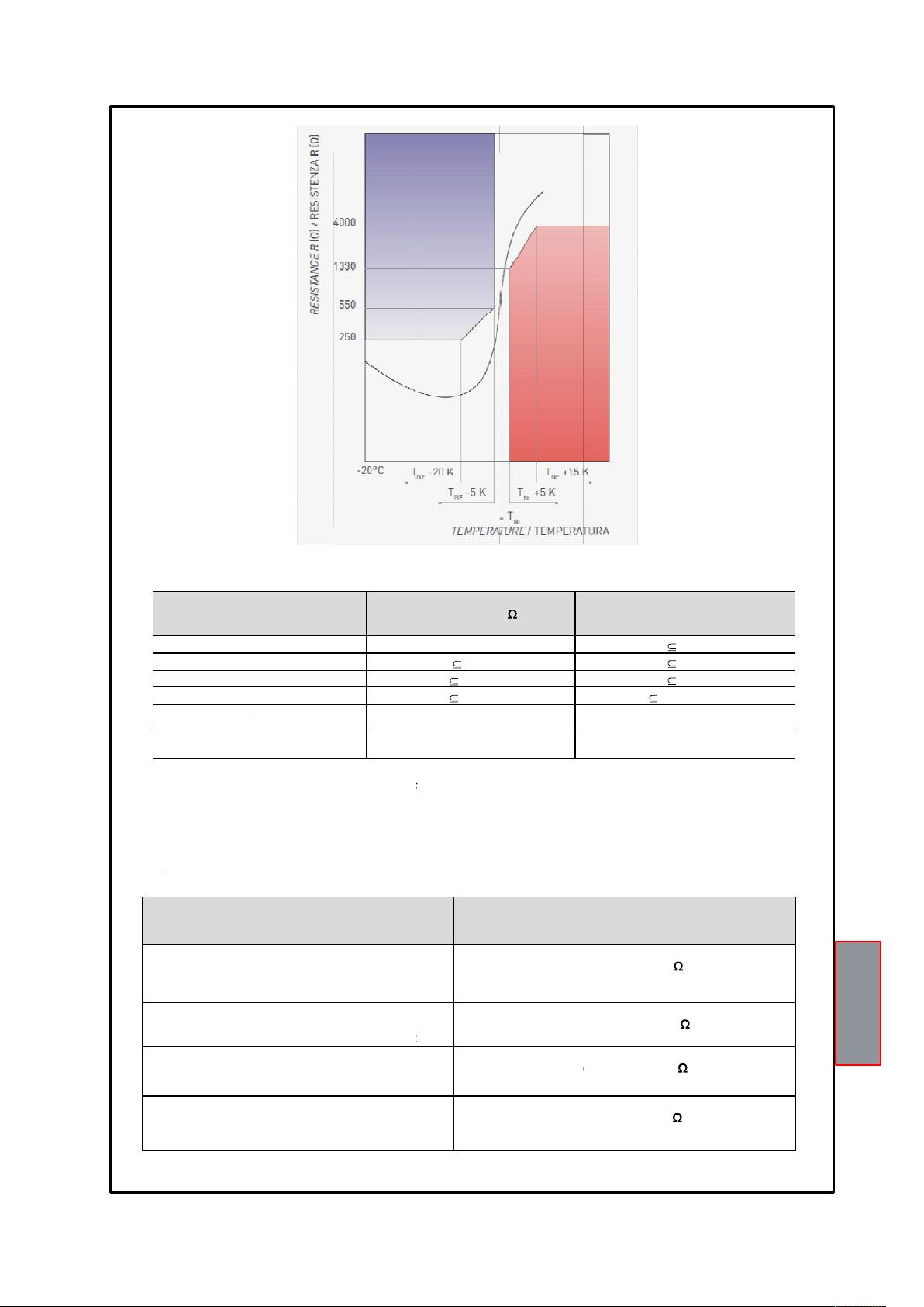
PTC TECHNICAL SPECIFICATIONS
PTC RESISTANCE VALUES ALLOWED FOR
CONNECTION TO T119 DIN
7) SENSOR / RELAY ELECTRICAL CONNECTIONS
8) WARRANTY CONDITIONS
9) TROUBLESHOOTING
10) EQUIPMENT DISPOSAL
11) USEFUL CONTACTS
PAGE
……….......................................
…………………………………..
…………………………………..
…………………………………..
…………………………………..
…………………………………..
…………………………………..
…………………………………..
…………………………………..
………………………………….
…………………………………..
…………………………………..
…………………………………..
…………………………………..
…………………………………..
…………………………………..
…………………………………..
…………………………………..
…………………………………..
…………………………………..
…………………………………..
…………………………………..
…………………………………..
…………………………………..
3
4
5
6
7
8
9
10
11
12
13
2
T119DIN
Page 3
SAFETY REQUIREMENTS
Read the manual carefully before starting to use the control unit. Keep the instructions for future reference.
Do not open the device, touching any internal components can cause electric shock. Contact with 110-240
Before connecting the device to the power supply, make sure that all the connections are correct. Always
disconnect the unit from the supply before any cabling modification.
Any intervention on the equipment must be entrusted to a qualified engineer.
Failure to comply with these instructions can cause damages, fires or electric shock, and possible serious
injuries!
POWER SUPPLY
The T119 DIN control unit has UNIVERSAL power supply, i.e. it can be supplied by 24 to 240 Vac-Vdc, irrespectively of
polarity in Vdc.
Before using it, make sure the power cable is not damaged, knotted or pinched. Do not tamper with the power cable.
Never disconnect the unit by pulling the cable, avoid touching the pins. Do not carry out any connecting/disconnecting
with wet hands. To disconnect the device, do not use objects such as levers. Immediately disconnect the device if you
smell burning or see any smoke: contact technical service.
LIQUIDS
Do not expose the equipment to splashes or drops, do not position it in places with humidity exceeding 90% and never
touch with wet or humid hands during storms. If any liquid penetrates the control unit, disconnect it immediately and
contact technical service.
CLEANING
Disconnect the power cable before cleaning the control unit, use a dry cloth to dust it, without any solvent or detergents,
and compressed air.
OBJECTS
Never insert any objects into the cracks of the control unit. If this happens, disconnect the control unit and contact an
engineer.
USE RESERVED TO QUALIFIED PERSONNEL
The purchased goods are a sophisticated electronic device that is totally unsuitable to be used by non-qualified
personnel. Any work must be carried out by a specialist engineer.
ACCESSORIES
The use of non-original accessories or spare parts can damage the unit and endanger users safety. In the event of
faults, contact technical service.
LOCATION
Install the control unit indoors, in a place protected from water splashes and sun rays. Do not place near heat sources
exceeding the parameters stated in this manual. Position on a stable surface, far from any possible vibrations. Position
the unit as far as possible from any intense magnetic fields.
REPAIRS
Do not open the control unit. For any fault, always use qualified personnel. The opening of the control unit and/or the
removal of the series identifying label entails the automatic forfeiture of the warranty. The Warranty seal is applied to all
devices, any attempt to open the unit would break the seal and cause the consequent automatic forfeiture of the
warranty.
TECHNICAL INFORMATION
Mail: [email protected] tel: 02/4581861
ATTENTION :
Volts can be fatal. To reduce the risk of electric shock, do not dismantle the back of the device for any reason.
Moreover its opening would void the warranty.
3
T119DIN
Page 4
ACCESSORIES
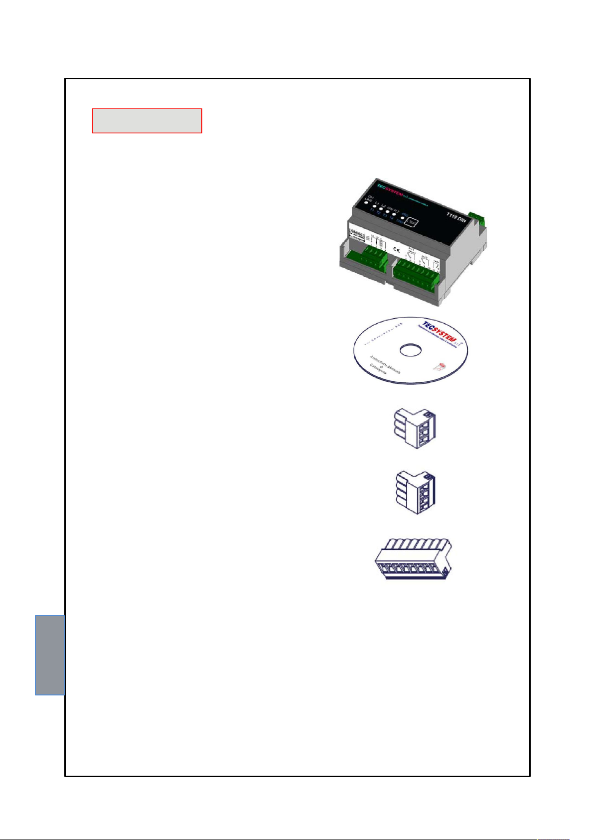
Control unit
Instruction manual CD
1 supply terminal 3 poles pitch 5
Code: 2PL0367
1 PTC sensor terminal 4 poles pitch 5
Code: 2PL0369
1 relay terminal 8 poles pitch 5
Code: 2PL0374
ATTENTION: always install the device using the terminals included in the pack.
The use of terminals other than those included with the control unit might cause malfunctions.
1MN0030 REV. 0
4
T119DIN
Page 5
TECHNICAL SPECIFICATIONS
AUXILIARY POWER SUPPLY
T119DIN
Supply rated values
Maximum ratings 20-270 Vac-dc
Vdc with reversible polarities
INPUTS
3 series of PTC inputs:
1 series for L1 (ALARM)
1 series for L2 (TRIP)
1 series for FAN
Connections to removable terminals
Input channels protected against electromagnetic interference
OUTPUTS
1 alarm relay (ALARM / FAULT AND TRIP) SPDT
1 ventilation management relay (FAN) with timed latch (5-10-20-40 min.) delay OFF SPST
Output relays with 5A-250Vac-res COS =1 contacts.
DIMENSIONS
24 -240Vac-dc
50/60HZ
106x90 mm DIN43880 depth58 mm (DIN track mounting)
TESTS AND PERFORMANCES
Assembly in compliance with EC rules
Protection against electrical and magnetic noises CEI-EN6100-4-4
Dielectric strength 1500 Vac for a min. between output relays and sensors, relays and power supply,
power supply and sensors
Working temperature from -20°C to + 60°C
Humidity 90% non-condensing
ABS self-extinguishing housing NORYL 94VO
T119DIN
5
Page 6
TECHNICAL SPECIFICATIONS
Demand 2 VA
Self-diagnostic circuit
Protection treatment of the electronic part
DISPLAY AND DATA MANAGEMENT
LED indicating alarm channel, trip or fan
LED indicating FAULT
2 alarm thresholds
1 ventilation control ON threshold
Access to programming via the frontal push button
Automatic exit from programming after 1 minute's inactivity
T119DIN
Option
INTRODUCTION
The T119 DIN is the most advanced unit on the market as regards temperature monitoring units for MV cast resin
transformers which utilize PTC sensors.
The unit gives the L1 pre-alarm and L2 alarm-trip signals when the temperature limits sensed by the PTCs in the coils are
reached.
The T119 DIN is set to control the cooling ventilation of the transformer. The T119 DIN continuously monitors the efficiency
of the PTC sensors and when one of these fails, an immediate alarm signal of faulty sensor is sent.
The FAN relay is energized so long as the temperature T° is higher than the NAT value; when T° gets below this value,
the relay is still energized for the set ventilation time (5-10-20-40) (DELAY OFF function).
As the PTCs currently produced by the various European manufacturers have different specifications, Tecsystem Srl is not
responsible for the control system malfunctioning due to PTCs with resistance values other than those indicated in table 1.
6
T119DIN
Page 7
FRONT
z
4
1
3
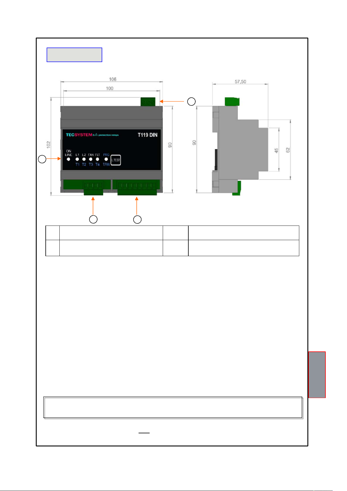
1) Universal unit supply 24-240 Vac-dc 50/60Hz. 3) Device operation LED
2) Relays (ALARM/FAULT- ALL2) 4) L1 - L2 - FAN PTC sensor lines
LED SIGNAL:
LED ON: "ON" The device is powered correctly "OFF" The device is not powered correctly
L1 LED:
"ON" L1 trip threshold exceeded "OFF" temperature below the L1 trip threshold.
L2 LED:
"ON" L2 trip threshold exceeded "OFF" temperature below the L2 trip threshold.
FAN LED:
"ON" FAN trip threshold exceeded "OFF" temperature below the FAN trip threshold.
FAULT LED - L1 LED - L2 LED - FAN LED flashing see PTC SENSOR FAULT DIAGNOSIS on page 10.
POWER SUPPLY
The T119 DIN control unit has UNIVERSAL power supply, i.e. it can be supplied by 24 to 240 Vac-Vdc, 50/60 H
irrespectively of polarity in Vdc (terminals 40-42).
This is obtained thanks to the use of a tested power supply unit, newly designed and manufactured, that frees
installers from worrying about the correct Vac or Vdc supply.
The ground cable must always be connected to terminal 41.
When the unit is supplied directly by the secondary of the transformer to protect, it can be burnt out by strong overvoltages.
This happens if the main switch is closed and the transformer has no load (blank test).
The above-mentioned problems are much more evident when the 220 Vac voltage is taken directly from the
transformer secondary bars and there is a fixed capacitor battery to phase the transformer itself.
2
(ON-L1-L2-FAN -FAULT)
1MN0109 REV. 0
To protect the control unit from line overvoltages, we suggest using the PT-73- 220 electronic discharger, designed by
TECSYSTEM S.r.l. for this specific purpose. As an alternative we suggest using supply voltages from 110 Vac or, much
better, 110 Vdc.
If an existing control unit must be replaced with a new one, to guarantee its correct and safe operation, the
sensor/relay/supply connecting terminals must be replaced with the new terminals supplied.
T119DIN
7
Page 8
PROGRAMMING
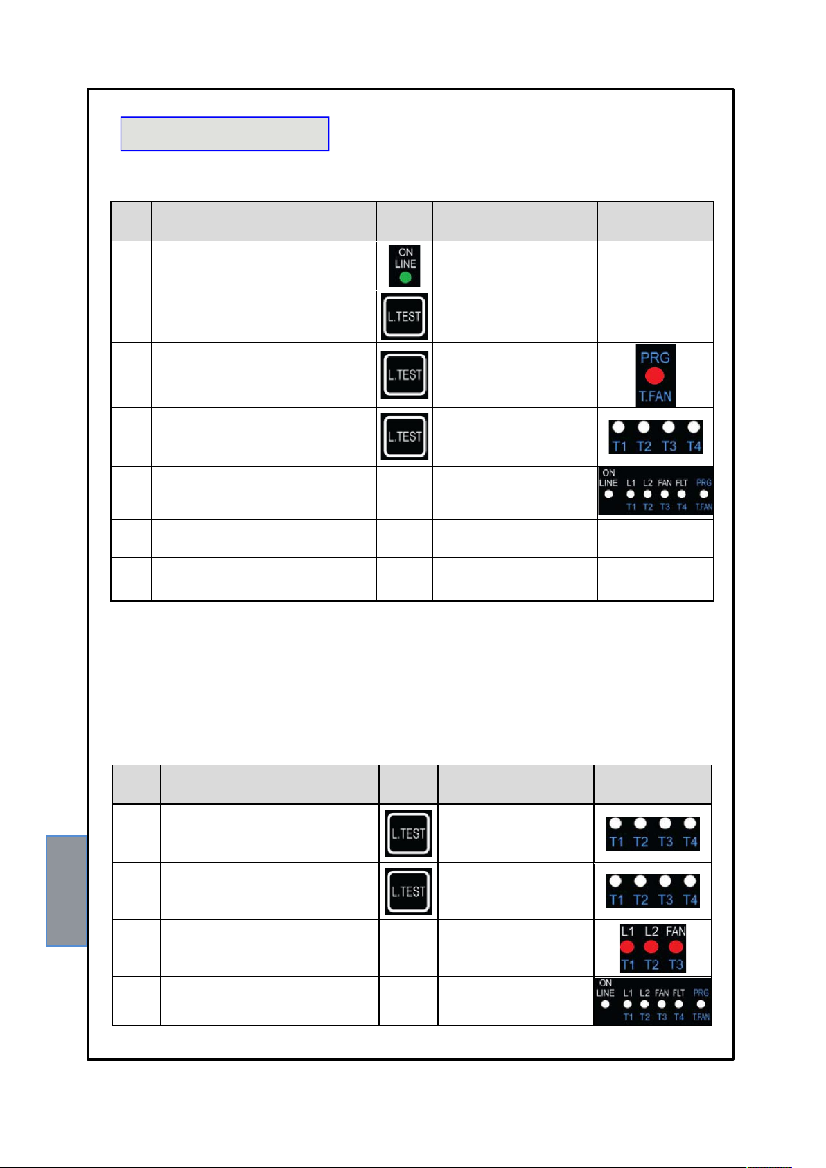
FAN PROGRAMMING CYCLE
STEP ACTION
Turn on the unit
1
Push TEST twice in sequence the red PRG LED flashes
2
Push TEST within 5" without releasing it until the
3
PRG LED is ON
Push TEST within 5" to select the desired FAN
4
time
Stop pressing TEST when the LED is on the Tx
corresponding to the desired time. Wait for all the
5
LEDs to go OFF.
End of programming
6
Turn the unit off and then back on
7
the green LED lights up
the PRG LED is ON continuously
the red LED switches from T1-T2T3-T4
(FAN time 5-10-20-40)
all the LEDs are switched OFF
EFFECT
To choose the FAN time (point 4):
Press TEST once to select 5' (T1 ON)
Press TEST twice to select 10' (T2 ON)
Press TEST three times to select 20' (T3 ON)
Press TEST four times to select 40' (T4 ON)
If you dont need any FAN cycle, push TEST 5 times (all LEDs are OFF). The unit is programmed only for ALL1 and
ALL2 (alarm and trip)
ALARM RELAY TEST
STEP ACTION
push TEST three times in sequence
1
Within 5 push TEST without releasing it until the
LEDs light up all together
2
after 5 the relay FAN lights up, followed by the
ALL1 and ALL2 relays
3
END OF THE TEST CYCLE
4
the T1,2,3,4 LEDs light up in
sequence
LEDs T1,2,3,4 flash all together
the LEDs and relays of FAN 1-
ALL1-ALL2 are ON
all the red LEDs go OFF
EFFECT
8
T119DIN
Page 9
LED TEST
We recommend the unit LEDS are tested regularly. For this operation press the TEST button briefly, all the leds light up
for 2 seconds.
If one of the LED does not work, please return the control unit to TECSYSTEM for repair.
ALARM 1 RELAY OPERATION
The ALL1 (L1) relay operates when the unit is powered, therefore the N.O. contact is closed. In case of an alarm on the
ALL1 (L1) PTC or a fault in the control unit itself, the relay gets de-energised with consequent closing of the N.C. contact.
The ALL1 (L1) relay also has the same function as the PTC sensor FAULT. If this relay is triggered when the PTC sensor
FAULT LED is FLASHING, it means that there is an error in the reading of a PTC sensor. It is possible to find it, thanks to
a second LED flashing which corresponds to the FAULT channel.
ALARM 2 RELAY OPERATION
The ALL2 (L2) relay is normally de-energized and energizes when there is an alarm on the L2 PTC.
FAN RELAY OPERATION (VENTILATION)
During programming, it is possible to set the cooling time or to exclude the FAN option. If the FAN is excluded, the relay
doesnt energize and for this reason it is possible not to install the corresponding PTC.
If the FAN is set up, the relay activates when the relative PTC sends the first signal and the FAN LED is steady ON: the
relay is active for as long as the PTC senses the temperature is normal, the T119 DIN unit keeps the relay ON for the time
set during programming and the FAN LED flashes.
DELAYED VENTILATION CYCLE (DELAY ON)
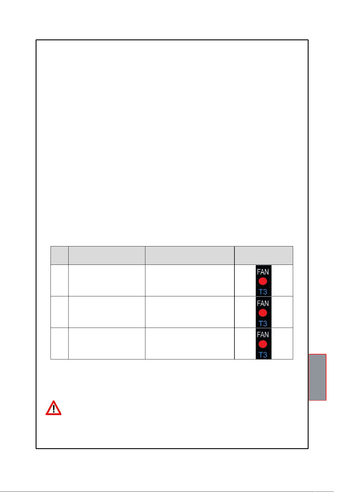
STEP
1 the FAN PTC sensor is ON the FAN relay is ON and the red LED is lit
the temperature goes below the PTC
2
value
the temperature raises again above the
3
PTC set threshold
ACTION
EFFECT
the FAN relay remains ON for the set time and
the red LED flashes
the LED is ON all the time
IMPORTANT WARNING
Before carrying out the isolation test of the electrical panel the control unit is installed on, disconnect it with the
sensors from the power supply to prevent it from being seriously damaged.
T119DIN
9
Page 10
SENSOR DIAGNOSTIC DEVICE
This new function allows enabling or disabling the PTC diagnostic device (Foc and Fcc):
Diagnostics disabling method:
power the instrument keeping the TEST button pressed until the FAULT LED comes ON
With the diagnostics disabled, the FAULT yellow LED will be ON all the time.
Diagnostics re-enabling method
Power the instrument keeping the TEST button pressed until all LEDs go OFF. With the diagnostics enabled, the FAULT
yellow LED will be OFF and flash in case of sensor faults.
The T119 DIN control units will be supplied with the sensor diagnostics ENABLED.
PTC SENSOR FAULT
ACTION
EFFECT
one of the PTCs is short-circuited
replace or repair the PTC
PTC SENSOR FAULT DIAGNOSIS
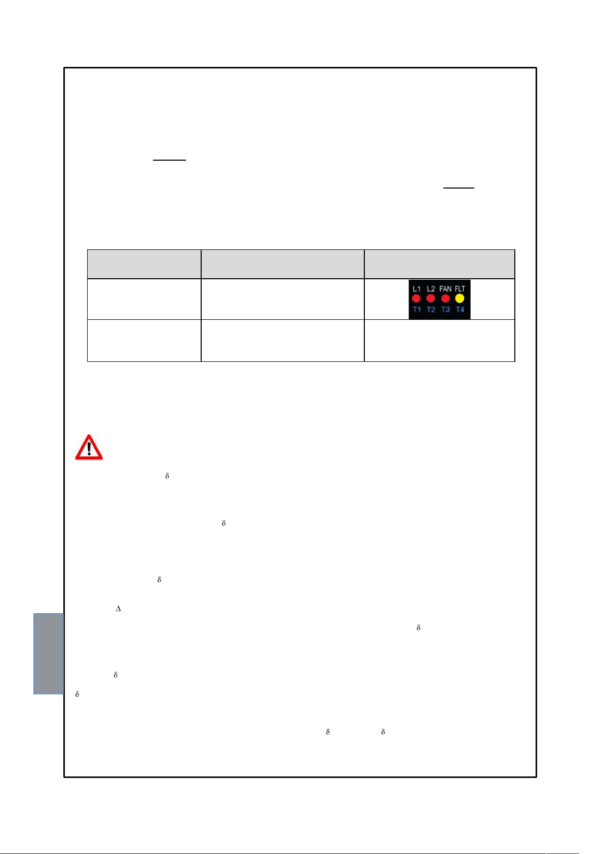
If one of the PTCs is short-circuited or open you get the following warnings:
PTC alarm ALL1(L1) The FAULT + ALL1 LEDs are flashing
PTC TRIP release ALL2(L2) The FAULT + ALL2 LEDs are flashing
PTC FAN FAN The FAULT +FAN LEDs are flashing
ATTENTION
If the T119 DIN control unit is not connected to the correct PTC model, the LEDS flash.
The PTC temperature is nat + T = 1300 ohm.
"PTC" TYPE TEMPERATURE SENSORS
The PTCs can be compared to bimetallic thermostats where the contact opens and closes at the approximate temperature,
defined as their operating characteristic ( NAT=operating temperature).
The thermostat is calibrated for one temperature only that can vary from 60 to 180°C, in 10°C steps (60-70-80-90-100-110120-130-140-145-150-155-160-170-180).
The electric contact of the bimetallic thermostat opens and closes at different temperatures, always approximately +/- of the
operating temperature NAT.
The difference between the opening and closing temperatures of the electric contact defines the operational differential of
thermostat T°.
Very precise and expensive bimetallic thermostats can adjust the temperature at +/- 1°C of NAT; the normal bimetallic
thermostats have an adjustment precision reaching 3-5°C.
The PTCs are electronic thermometric sensors made with a chemical mixture that vary their electrical resistance according
to the recorded temperature.
There is a NAT (operating temperature) for the PTCs as well as for the bimetallic thermostats.
The PTCs do not allow precision adjustments since the characteristic resistance values are fixed at 5°C and +5°K of
NAT.
The PTC characteristic resistance values are set by the DIN 44081 and 44082 standards.
Since the PTC resistance curve is very rapid, in the section between NAT -5°C and NAT +5°C, it is quite difficult to make
adjustments in a temperature span of less than +/- 5°K.
If you use high temperature alarm systems, they obviously do not offer the device a high degree of precision.
the FLT yellow LED and the corresponding LED
(ALL1-ALL2-FAN) are flashing
the LEDs go OFF
10
T119DIN
Page 11
C
e
e
rv
T
a
Table 1
E
t
d
d
N
c
p
E
u
t
T
o
i
t
c
e
T
L
b
c
s
A
n
o
C
b
r
R
N
E
5
T
p
w
e
5
C
r
e
G
H
G
O
D
7
5
e
S
0
0
0
5
T
P
TC TECHNICA
L SPECIFICA
IONS
From 20
Maximum o
PT
RESISTANC
Th
resistance val
Th
correct opera
mul
tiple series of
Se
ice.
emperature
Al
rm thresholds
Sensor d
TEMP
From
From
From d
Electri
Sensor
RATURE
o dNAT-20°K
NAT 5°K
NAT +5°K
AT +15°K
stiffness
erating voltag
VALUES AL
e shown in ta
ion of the devi
PTCs have re
f the machine
reached for F
diagnostics i
agnostics sh
FUNCTION
NO ALARM
thresholds
ALARM
FOC
FCC
OWED FOR
le 1 refers to a
e is obtained
istance values
below the ala
N-ALL-L1-T
terrupted
rt-circuited
RESISTANC
From 20 to 2
550
1330
4000
ONNECTION
single or multi
y complying
other than th
m
IP-L2
0
O T119 DIN
le series of PT
ith the stated
stated, pleas
HI
HIG
HI
MEASURE
s.
esistance valu
contact TEC
RESISTANCE
HER THAN 5
ER THAN 18
HER THAN 10
L
WER THAN 3
VOLTAGE V
2,5
2,5
2,5
.5 pulsed
2
00 Vac
30
s. In case the
YSTEM Srl -
0
K
DC
single or
echnical
11
T119DI
Page 12
SENSOR / RELAY ELECTRICAL CONNECTIONS
1
2
3
1MN0109 REV. 0
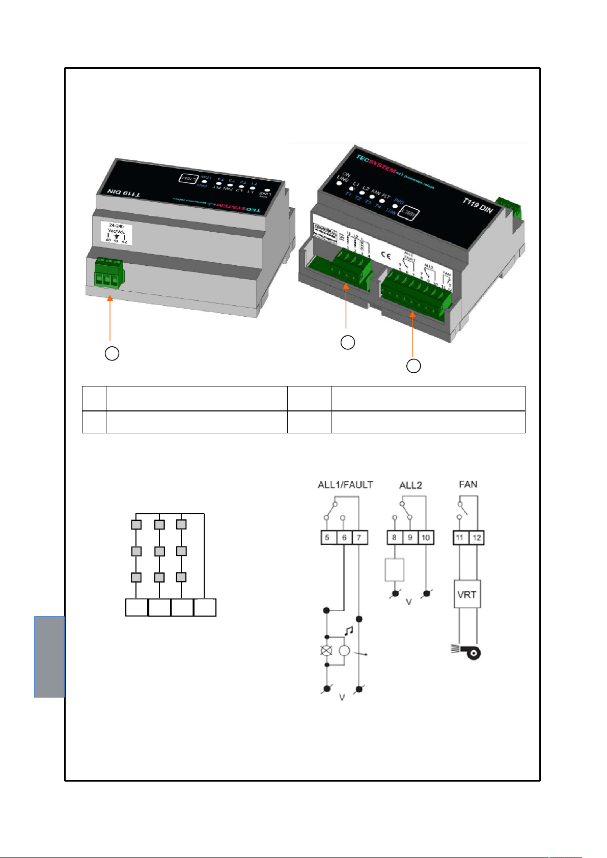
1) Universal unit supply 24-240 Vac-dc 50/60Hz. 3) Relays (ALARM/FAULT-ALL2-FAN)
2) L1 - L2 - FAN PTC sensor lines
PTC SENSORS
L1 L2 FAN COM
RELAYS
CH1
CH2
CH3
ALARM / FAULT
AUDIO AND
VISUAL INDICATION
STOP
SYSTEM
1MN0095 REV. 0
The ALARM / FAULT relay operates normally when the unit is powered, therefore contact 5-7 is closed. The above
picture shows the state of the relays in non-alarm condition.
12
T119DIN
Page 13
T
c
f
o
r
c
r
s
o
r
T
e
e
n
d
a
Y
H
E
D
W
E
W
A
U
E
d
e
e
e
o
a
e
2
p
r
a
e
r
s
e
e
f
N
T
T
T
T
t
T
y
o
p
o
s
t
W
a
a
/
y
c
U
N
D
t
u
b
d
e
e
t
u
1
s
e
u
d
S
e
t
S
N
n
n
u
s
s
d
d
n
e
h
H
a
l
t
d
p
r
A
e
v
n
o
e
o
t
d
s
u
g
n
n
l
s
W
o
N
t
h
a
o
e
b
C
e
q
h
e
w
r
N
r
T
o
r
e
h
u
c
s
e
w
r
The Pr
"Tecsys
The wa
manufa
The wa
voltage
instructi
The wa
RRAN
duct purchas
tem s.r.l's Gen
ranty is consid
turing or comp
ranty is invalid
outside the s
n manual.
ranty is always
Y CON
d is covered b
ral Conditions
ered valid only
onent defects.
if the Product
t limits and d
ex Corsico as
ITIONS
the manufact
f Sale", availa
when the pro
roves to have
es not comply
tated in the "G
rer's or seller'
le at www.tec
uct is damage
been tampere
with the tech
neral Conditio
warranty at th
ystem.it and /
by causes at
with / modifie
ical data for u
ns of Sale".
e terms and c
r purchase agr
ributable to TE
or incorrectly
e and assem
nditions set fo
ement.
CSYSTEM srl,
connected and
ly, as describ
th in the
such as
causing
d in this
have th
N.B. To
The
corres
One o
EQ
Europ
electro
on the
Returni
dispos
TECS
correct
ecsystem Srl
resistance fe
verify the corr
ROUBL
ontrol unit
ponding LED is
the two PTC li
IPMEN
an directives
ic waste and
isposal of the
All the electric
European dir
equipment ma
ng used elect
l of the device
STEM is awar
and environm
is not responsi
tures shown in
ct operation of
ESHOO
oes not swi
OFF.
nes is in FAUL
DISPO
012/19/EC (
romote the rec
esidues and h
l and electroni
ctive 2002/96
rked with this s
ical devices: c
.
of the impact
ntally-friendly d
ble for damag
table 1.
he monitoring
ING
ch on, the
alarm
SAL
EEE) and 20
ycling and reu
rmful compon
c equipment s
EEC on elect
mbol must be
ontact TECSY
its products ha
isposal of its d
s caused by t
nit in all its fun
Switch the u
tightened and t
Check the co
Replace the fa
10.
1/65/EC (Ro
e of the materi
nts of electrica
pplied after 13
rical and elec
isposed of se
TEM or your
ve on the envi
vices.
e monitoring
ctions, we sug
CAUSES
it off and ch
here are no ob
tinuity and c
lty sensor, se
S) have bee
ls and compo
and electronic
August 2005 i
ronic waste (
arately from n
TECSYSTEM
onment and as
nit due to PT
est you use th
ND SOLUTIO
ck that: the
ious burns on
nnection of t
PTC sensor f
approved to
ents of said e
materials.
marked with t
EEE). Any
rmal domestic
agent for infor
ks its custome
sensors whic
SIM-PTC sim
S
connecting wi
he connectors.
e relative P
ult diagnosis
reduce electri
uipment, cuttin
is symbol, pur
lectrical or el
aste.
mation on the
s active suppo
do not
lator.
es are
C line.
n page
al and
g down
uant to
ctronic
correct
t in the
US
TEC
SAL
PRO
DO
ACC
FUL CON
NICAL INF
S INFO : in
UCT INFO
NLOAD CO
SSORIES
ACTS
O : ufficiote
o@tecsystem
(CATALOG
TROL UNI
nico@tecsys
.it
ES)
T MANUAL
em.it
13
T119DI
 Loading...