

Page 1
1MN0158 REV. 0
operates with ISO9001 certified quality system
http://www.tecsystem.it
R. 1.0 10/09/2018
“Translations of the original instructions”
ENGLISH
TECSYSTEM S.r.l.
20094 Corsico (MI)
Tel.: +39-024581861
Fax: +39-0248600783
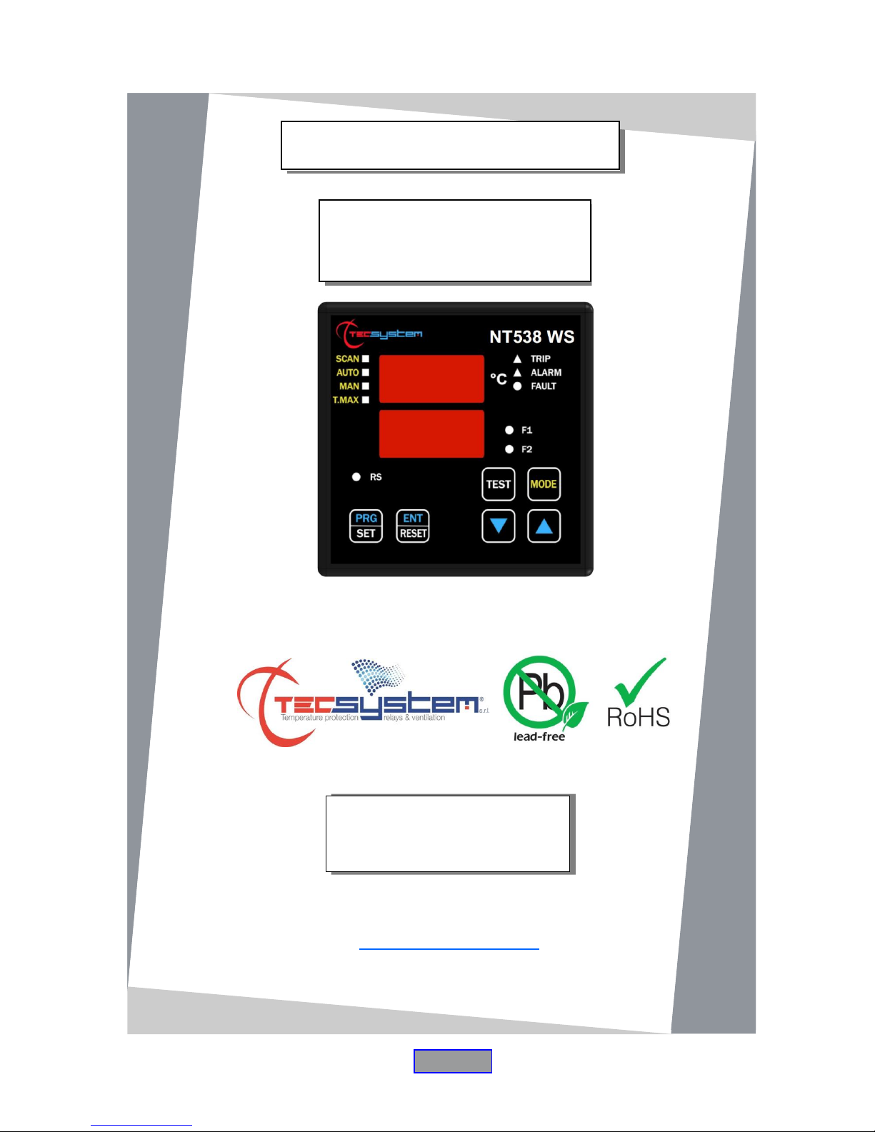
NT538 WS
INSTRUCTION MANUAL
Page 2

2
NT538 WS
PAGE
1) SAFETY REQUIREMENTS
………..........................................
4
2) ACCESSORIES
…………………………………..
5
3) TECHNICAL SPECIFICATIONS
…………………………………..
6
4) FRONT PANEL
…………………………………..
8
DISPLAY
…………………………………..
9
OPERATING PROGRAM CONTROL
………………………………….
—
NOTES ON SCAN AND MAN FUNCTIONS
…………………………………..
—
LED TEST
…………………………………..
—
ALARM RELAY TEST
…………………………………..
—
ALARM RELAY SILENCING
…………………………………..
—
5) MOUNTING
…………………………………..
10
6) ELECTRICAL CONNECTIONS
…………………………………..
11
NT538 WS BACK
…………………………………..
—
POWER SUPPLY
…………………………………..
12
ALARMS AND VENTILATION
…………………………………..
—
FAULT AND RESET MESSAGE SEQUENCE
…………………………………..
—
7) PROGRAMMING
…………………………………..
13
NT538 WS
…………………………………..
—
PROGRAMMING NOTES
…………………………………..
14
TEMPERATURE SENSORS
…………………………………..
15
MEASUREMENT SIGNAL TRANSFER
…………………………………..
—
TEMPERATURE SENSOR DIAGNOSTICS
…………………………………..
16
VOTING FUNCTION
…………………………………..
—
PROGRAMMED DATA DIAGNOSTICS
…………………………………..
17
TEMPERATURE DIAGNOSTICS
…………………………………..
—
COOLING FAN CONTROL
…………………………………..
—
FAN TEST
…………………………………..
—
CONTENTS
First of all we wish to thank you for choosing to use a TECSYSTEM product and recommend you read this instruction
manual carefully: You will understand the use of the equipment and therefore be able to take advantage of all its
functions.
ATTENTION! THIS MANUAL IS VALID AND COMPLETE FOR THE NT538 WS CONTROL UNIT
Page 3

3
NT538 WS
PAGE
8) FAILSAFE FUNCTION
…………………………………..
18
9) TECHNICAL SPECIFICATIONS OF THE EXTENSION
CABLE FOR Pt100
…………………………………..
—
10) FCD FUNCTION
…………………………………..
19
11) NT538 WS WIFI CONNECTION
…………………………………..
—
12) TECSYSTEM WEB SERVER
…………………………………..
21
WEB SERVER MANAGEMENT BAR
…………………………………..
22
HOME SCREEN
…………………………………..
—
SETTINGS SCREEN
…………………………………..
23
NETWORK SETTINGS
…………………………………..
24
OPTIONS
…………………………………..
25
GRAPHICS SCREEN
…………………………………..
26
EVENTS SCREEN
…………………………………..
27
GRAPHIC VIEW NOTES
…………………………………..
28
EXPORT NOTES CSV FILE
…………………………………..
—
PIN CODE
…………………………………..
—
13) TROUBLESHOOTING
…………………………………..
29
14) WARRANTY CONDITIONS
…………………………………..
—
15) EQUIPMENT DISPOSAL
…………………………………..
30
16) USEFUL CONTACTS
…………………………………..
—
Page 4
4
NT538 WS
SAFETY REQUIREMENTS
ATTENTION:
Carefully read the manual before starting using the control unit. Keep the instructions for future reference.
Do not open the device, touching any internal component can result in electric shock as voltages over 50 volts
can be lethal. In order to reduce the risk of electric shock, do not disassemble the back of the device. Warranty shall be
void if device is opened.
Before connecting the device to the power supply, ensure that all the connections are correct. Always disconnect
the unit from the supply before making any modification on the wiring.
Any operation on the equipment must be operated by a qualified technician.
Failure to comply with these instructions can cause damages, fires or electric shock, and possible serious
injuries!
POWER SUPPLY
The NT538 WS control unit has UNIVERSAL power supply, i.e. it can be supplied from 85 to 260 Vac-Vdc, irrespectively
of polarity in Vdc. Before use, ensure that the power cable is not damaged, knotted or pinched. Do not tamper with the
power cable. Never disconnect the unit by pulling the cable, avoid touching the clamps. Do not carry out any
connecting/disconnecting operation with wet hands. To disconnect the device, do not use objects such as levers.
Immediately disconnect the device if you smell burning or see any smoke: contact technical service.
LIQUIDS
Do not expose the equipment to liquid spurts or drops, do not position it in places where humidity exceeds 90% and
never touch it with wet or humid hands during storms. If any liquid penetrates the control unit, disconnect immediately
and contact technical service.
CLEANING
Disconnect the power cable before cleaning the control unit, using a dry cloth without any solvent or detergent, and
compressed air.
OBJECTS
Never insert objects into the openings of the control unit. If this happens, disconnect the control unit and contact technical
service.
USE RESERVED TO QUALIFIED PERSONNEL
The purchased good is an advanced electronic device that should not be used by non-qualified personnel. Any operation
must be carried out by a qualified technician.
ACCESSORIES
The use of non-original accessories or spare parts may damage the unit and endanger users' safety. In event of fault,
contact technical service.
LOCATION
Install the control unit indoor, in a place protected from water splashes and sun rays. Do not place near heat sources if
exceeding the parameters stated in this manual. Position on a stable surface, far from any possible vibrations. Position
the unit as far as possible from intense magnetic fields..
REPAIRS
Do not open the control unit. In case of fault, always contact qualified personnel. The opening of the control unit and/or
the removal of the series identifying label automatically make the warranty void. The warranty seal is applied to all
devices, any attempt to open the unit would cause the seal to break the consequent automatic cancellation of the
warranty.
FUNCTION
To control the transformer correctly from a temperature point of view, enabling the VOTING function is allowed
where the load distributed between the phases of the transformer is adequately balanced.
TECHNICAL INFORMATION
Mail: [email protected] — tel: 02/4581861
Page 5
5
NT538 WS
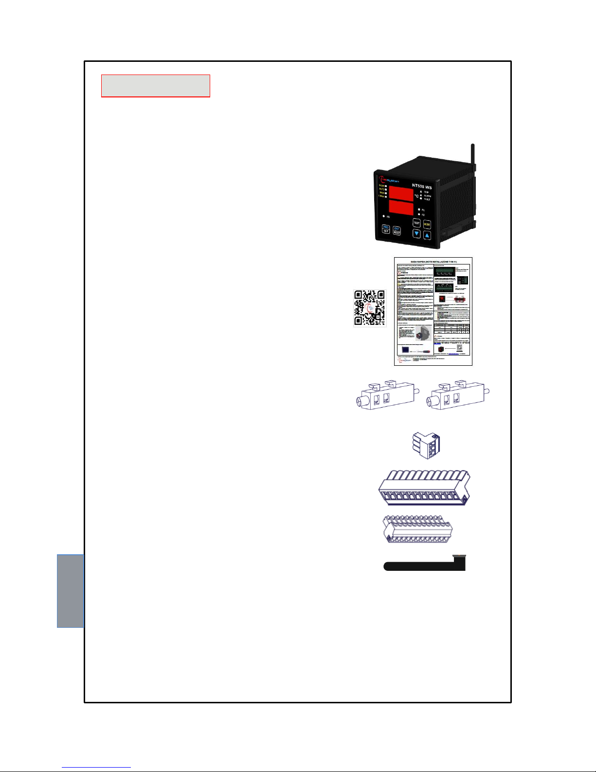
The following objects are present inside the box:
Control unit
Start guide and QR code
2 blocks for panel mounting
1 supply terminal 3 poles pitch 5
Code: 2PL0367 - Screws tightening torque 0.5Nm
1 relay terminal 12 poles pitch 5
Code: 2PL0361 - Screw tightening torque 0.5Nm
2 Pt100 sensors terminals 12 poles pitch 3.81
Code: 2PL0430 - Screws tightening torque 0.25Nm
1 external Wi-Fi SMA Antenna
ACCESSORIES
ATTENTION: always install the device using the terminals included in the pack.
The use of terminals other than those included with the control unit might cause malfunctions.
Page 6

6
NT538 WS
TECHNICAL SPECIFICATIONS
NT538 WS
POWER SUPPLY
Supply rated values
85-260 Vac-Vdc
50/60HZ
Vdc with reversible polarities
●
INPUTS
8 inputs for RTD sensors, Pt100 type with 3 wires (max section 1.5mm²)
●
Connections on removable terminal strips
●
Input channels protected against electromagnetic interference
●
Cable compensation for thermistors
500m (1 mm²)
OUTPUTS
2 alarm relays (ALARM AND TRIP) SPDT
●
1 sensor or operating failure (FAULT) relay SPST
●
Output relays with 10A-250Vac-res COSФ=1 contacts.
●
2 ventilation management relays (FAN 1 and FAN 2) SPST
●
Wi-Fi Connection: protocol 802.11 b/g/n, frequency 2.4 GHz with removable external antenna
Max 100m
in open field
DIMENSIONS
100 x 100 mm DIN 43700 depth 150 mm (including antenna - installed at 90° - and terminal
board)
Hole 92 x 92 mm
TESTS AND PERFORMANCE
Construction in compliance with CE regulations
●
Protection from electrical interference EN 61000-4-4
●
Dielectric strength 1500 Vac for a min. between output relays and sensors, relay and power
supply, power supply and sensors
●
Accuracy ±1% full scale value, ±1 digit
●
Ambient operating temperature from –20°C to +60°C
●
Humidity 90% non-condensing
●
Frontal film polycarbonate IP65
●
Page 7

7
NT538 WS
TECHNICAL SPECIFICATIONS
NT538 WS
Housing NORYL 94 _V0
●
Absorption 7.5VA
●
Digital linearity of sensor signal
●
Self-diagnostic circuit
●
Protection treatment of the electronic part
Optional
DISPLAY AND DATA MANAGEMENT
2 x 13 mm displays with 3 digits to display temperatures, messages and channels
●
3 LEDs to display the state of the alarms of the selected channel (ALARM-TRIP-FAULT)
●
4 leds selection of display mode (SCAN-AUTO-MAN-T-MAX)
●
2 LEDs to display the state of FAN1 and FAN2
●
Temperature control from 0°C to 240°C (*)
●
1 ALARM threshold for each channel
●
1 TRIP threshold for each channel
●
2 ON-OFF thresholds ventilation FAN1 and FAN2 in common for all the enabled channels
●
Sensor diagnostics (Fcc-Foc-Fcd)
●
Data memory diagnostics (Ech)
●
Access to programming through front keyboard
●
Automatic exit from programming, display and relay test after 1 minute of inactivity
●
Incorrect programming warning
●
Selection between channels automatic scanning, hottest channel or manual scanning
●
Storage of maximum temperatures reached by channels and alarm status
●
Front key to reset the alarms
●
Voting Function
●
Fail Safe Function
●
WEB SERVER Wi-Fi Function
●
Synchronization with SERVER NTP (Network Time Protocol) in STATION mode
●
(*) On demand, available version from -40°C to 200°C with alarm temperature management range from 0°C to 200°C
Page 8
8
NT538 WS
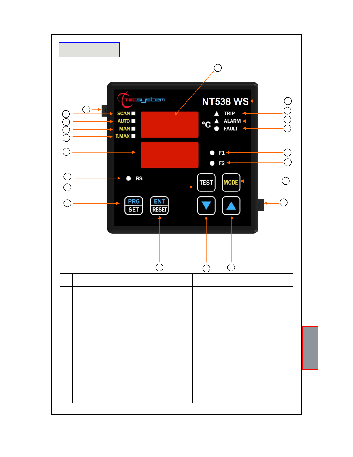
1)
3-digit temperature display
12)
Enter/Reset button
2)
Control unit series
13)
Programming/Setting key
3)
TRIP (red) LED
14)
Led/relay test key
4)
ALARM (yellow) LED
15)
RS (green) LED
5)
FAULT (red) LED
16)
3-digit channel display
6)
FAN 1 (yellow) LED
17)
T-max mode selection (red) LED
7)
FAN 2 (yellow) LED
18)
Man mode selection (yellow) LED
8)
Display mode selection key
19)
Auto mode selection (green) LED
9)
Fixing block
20)
Scan mode selection (yellow) LED
10)
UP key
21)
Fixing block
11)
DOWN key
FRONT PANEL
1
2 3 4 5 6 7 8
9
10
11
12
14
13
15
16
17
18
19
20
1MN0123 REV. 0
21
Page 9

9
NT538 WS
DISPLAY
The first display is dedicated to temperatures.
The second display to the monitored channel.
When the device is switched on or after a reset, the model of the NT538 control unit, the type of sensors, VER "00"
(firmware version), the temperature range of the device and the WS (web server) identification are always shown on the
display.
Pressing the MODE key, the display modes can be set:
SCAN: the control unit shows in scanning (every 2 seconds) all the enabled (°C) and disabled (NO) channels.
AUTO: the control unit displays the hottest channel automatically.
MAN: manual reading of the channel temperature using the up/down keys.
T.MAX: the control unit displays the maximum temperature reached by the sensors, any situations of alarm or fault that
have occurred since the last reset. Select channels with cursors , reset the values with RESET.
OPERATING PROGRAM CONTROL
To control the protection levels programmed, press the PRG key twice to access the VIS programme. Repeatedly pressing
the PRG key, you can scroll through all the previously loaded values in sequence.
After 1 minute's keyboard inactivity, the programming display procedure is automatically abandoned.
To stop the display, press the ENT key.
NOTES ON SCAN AND MAN FUNCTIONS
During the SCAN and MAN modes, the operation of the NT538 can be displayed.
1) RUN cPU:
This message appears when the device is turned on.
2) Ech Err:
This message appears when damage in the EEPROM memory is detected.
Pressing Reset will cancel the message and restore the original default parameters, listed in the programming
paragraph on pages 13-14. Return the control unit to TECSYSTEM for repairs.
3) CAL Err:
This message appears when damage is found in the measurement circuit.
The temperature values displayed might be incorrect. Return the control unit to TECSYSTEM for repairs.
4) Pt Err :
This message appears when it is detected that one or more PT100 sensors are not working correctly, FOC, FCC
and FCD indications in the temperature sensor diagnostics paragraph on page 16.
In case of Err the FAULT relay will be de-energised.
The above messages will be displayed following the 1-2-3-4 priority stated.
NOTE: in any display mode in case of faulty sensor failure (fcc, foc or fcd) the control unit will automatically set up in SCAN
mode (PRIVILEGED SCAN) allowing immediate displaying of the fault condition on the relative CHn channel (the Mode
key is disabled ).
LED TEST
We suggest carrying out the control unit LED test regularly.
For this operation, press the TEST key briefly; all the displays turn on for 2 seconds.
If one of the LEDS does not work, please return the control unit to TECSYSTEM for repair.
ALARM RELAY TEST
This function allows you to carry out a test of the relay operation without having to use further devices. To start the test
procedure, press and hold the TEST button for approximately 5 seconds: the TST indication appears for 2 seconds
confirming entry into the Relays Test mode.
Press the SET and RESET keys to energise and de-energise the relay to be tested; the display will show ON-OFF.
After 1 minute's keyboard inactivity, the RELAY TEST procedure will be automatically abandoned.
To stop the RELAY TEST procedure, press the TEST key.
Alternatively it is possible to use the PT100 model simulator: SIM PT100.
ALARM RELAY SILENCING
If you want to silence the ALARM signal press the RESET key: the relay de-energises and the ALARM LED, which was
fixed, will start flashing.
Silencing is automatically disabled when the temperature goes below the ALARM threshold.
Page 10
10
NT538 WS
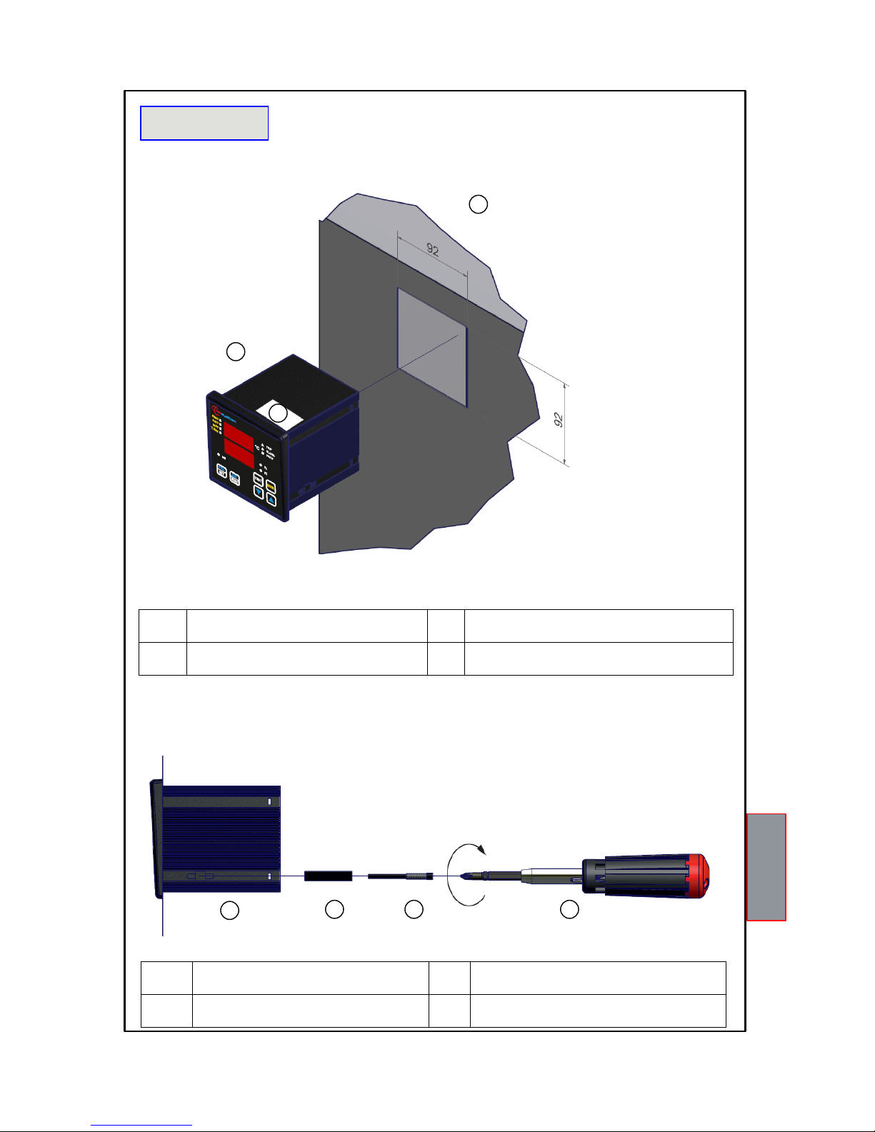
Fix the unit securely with the blocks supplied.
Connect the Wi-Fi antenna only after suitably fixing the device.
1)
Control unit
2)
Panel hole dimensions (+0.8 mm tolerance)
3)
Identification label
1)
Control unit
3)
Locking screws
2)
Fixing blocks
4)
Cross-head screwdrive #1X100mm
MOUNTING
1
1MN0007 REV. 0
2
3
1
2 3 4
1MN0008 REV. 0
Drill a 92 x 92 mm hole in the panel sheet.
Page 11
11
NT538 WS
NT538 WS
SCREEN
RED
RED
WHITE
ELECTRICAL CONNECTIONS
1 2 3
4
1MN0095 REV. 0
Output relay with 10A-250Vac-res COSФ=1 contacts.
STOP
SYSTEM
INDICATION
AUDIBLE AND VISUAL
ALARM CONDITION
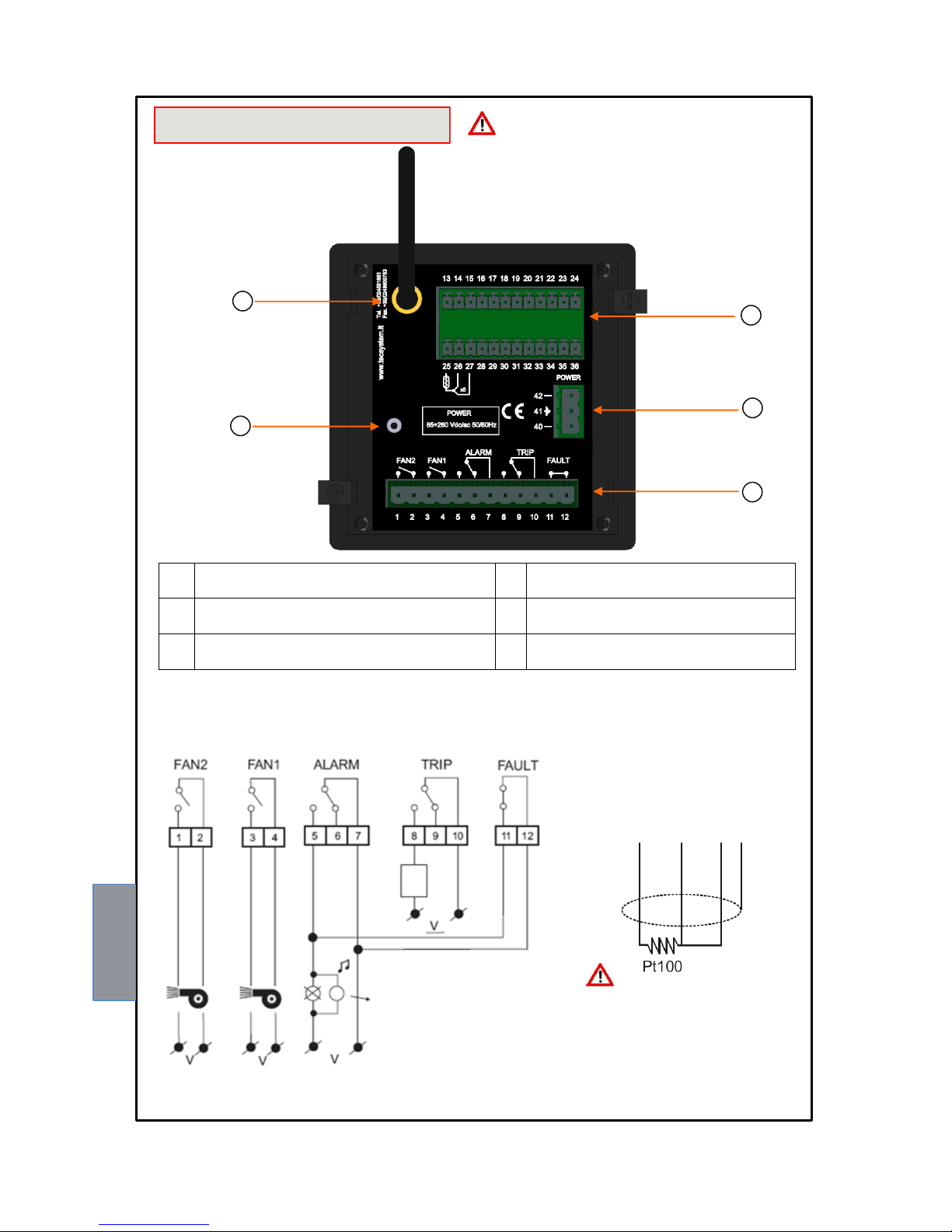
EXAMPLE Pt100 CONNECTION
Note: before connecting the
sensors to the control unit,
carefully read the paragraph
measurement signal transfer on
page 15.
Note: image relay contacts in non-alarm condition, except for the FAULT relay which opens: contacts 11-12 open
(NO) contacts 11-12 closed (NC) fault condition identification. Read paragraph Alarms and Ventilation p. 12 and see
image of fault contact opening.
RELAYS CONNECTION EXAMPLE
5
1)
Pt100 sensors (white-red-red)
4)
Access point key
2)
Power supply 85-260Vac-dc 50/60Hz.
5)
Antenna and Wi-Fi connector
3)
Relays (FAN2-FAN1-ALARM-TRIP-FAULT)
The Wi-Fi antenna (5) is supplied with the NT538 WS device. If
necessary, the antenna connection can be extended using a 5
mm SMA Male to Female antenna cable.
NOTE: Never start the device with the antenna
disconnected.
1MN0158 REV. 0
Page 12
12
NT538 WS
POWER SUPPLY
The NT538 WS control unit has UNIVERSAL power supply, i.e. it can be supplied by 85 to 260 Vac-Vdc, 50/60 Hz
irrespectively of polarity in Vdc (terminals 40-42).
This is obtained thanks to the use of a tested power supply unit, newly designed and manufactured, that frees installers from
worrying about the correct Vac and Vdc supply.
The earthing cable must always be connected to terminal 41.
When the control unit is powered directly by the secondary of the transformer to be protected, it can be burnt out by high
intensity overvoltages.
These problems occur if the main switch is closed and the transformer does not have the load (no load test).
The above is much more evident when the 220 Vac voltage is taken directly from the bars of the
secondary of the transformer and there is a fixed capacitor battery for power factor correction of the transformer itself.
To protect the control unit against line overvoltages, the PT-73-220 electronic arrester, designed by TECSYSTEM S.r.l. for
this specific purpose, is recommended. Alternatively, it is advisable to use 110 V AC supply voltages or, even better, 110
VDC.
If an existing control unit must be replaced with a new one, to guarantee its correct and safe operation, the
sensor/relay/supply connecting terminals must be replaced with the new terminals supplied.
ALARMS AND VENTILATION
Carry out the electrical connections on the removable terminal blocks only after disconnecting them from the unit.
When the unit is located in one of the methods described below does not monitor heat, also the relay will all be banned:
The fault contact switches and the fault LED flashes.
Vis. Programming display.
PRG programming.
Relay test.
The ALARM and TRIP relays only switch when the set temperature thresholds are exceeded.
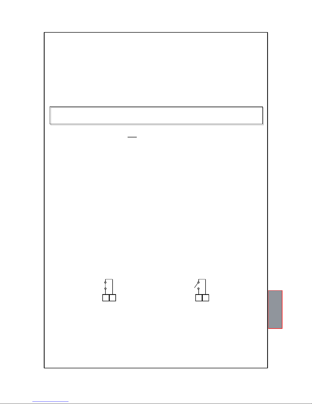
The FAULT (fault) contact, programmed in active failsafe mode (default YES), opens (11-12) when the appliance is
powered, only if during the access phase the control unit does not detect anomalies, and keeps the switching until when
one of the following events occurs:
Data memory fault (Ech message).
Pt100 sensor fault (FCC short-circuited sensor, FOC interrupted sensor or Fcd quick temperature increase)
CAL damage to the measurement circuit.
Insufficient supply voltage.
During the power on reset after programming (PRG), displaying the data (VIS) and test relay.
The FAULT failsafe mode can be disabled FAULT failsafe "NO" see programming step 30-31 page 14.
NOTE: in order to avoid unwanted system outages, do not connect the FAULT relay to the transformer tripping circuit.
FAULT AND RESET MESSAGE SEQUENCE
Find below the sequence of fault messages and RESET function condition.
1) ECH
2) CAL
3) FCD
4) ERR PT
The FAN1 and FAN2 contacts can be used to control the cooling fans, or they can be inserted in the conditioning system of
the transformer room, see paragraph cooling fan control on page 17.
NOTE: always disconnect the unit before performing any electrical connections.
11 12
FAULT 11-12 NC: ALARM FAULT OR POWER OFF
FAULT 11-12 NO: POWER ON OR NO FAULT
11 12
FAULT CONTACT (failsafe active)
eeprom fault
measurement circuit fault
quick temp. increase fault
FCC or FOC sensor fault
erasable message
erasable message
resettable condition
non-resettable condition
Page 13
13
NT538 WS
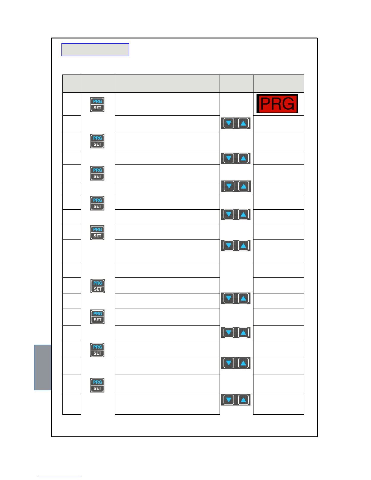
PROGRAMMING
NT538 WS
STEP
PRESS
EFFECT
PRESS
NOTES
1
Keep the PRG key pressed until the display shows PRG
SET
2
Select PRG SET for entering in the programming mode
or PRG 1 to restore the default programmed value.
PRG 1 default data
3
The display shows CH1
Enabling CH1
with YES the CH1 is
enabled
with NO the CH1 is
disabled
4
Select YES or NO
5
The ALARM CH1 threshold for is displayed
Set the desired threshold, the Alarm LED flashes
Default 90°C
6
Set the desired threshold
7
The TRIP threshold appears for CH1
the led Trip flashes.
Default 119°C
8
Set the desired threshold
9
The display shows CH1 FAN YES
the Fan1-2 LEDs flash.
info fan operation:
paragraph fan command
page 17
10
Select: YES FAN1+FAN2 enabled flashing
YES only FAN1 enabled flashing
YES only FAN2 enabled flashing
NO led FAN1- FAN2 off
Default YES FAN1+FAN2
11
Repeat the steps listed above for all the channels
CH2-CH8.
12
The display shows ON
the LED FAN1 flashes
Default 70°C
13 Set the desired threshold FAN1 ON
14
The display shows OFF
the LED FAN1 flashes
Default 60°C
15
Set the desired threshold FAN1 OFF
16
The display shows ON
the LED FAN2 flashes
Default 45°C
17 Set the desired threshold FAN2 ON
18
The display shows OFF
the LED FAN2 flashes
Default 35°C
19 Set the desired threshold FAN2 OFF
Page 14
14
NT538 WS
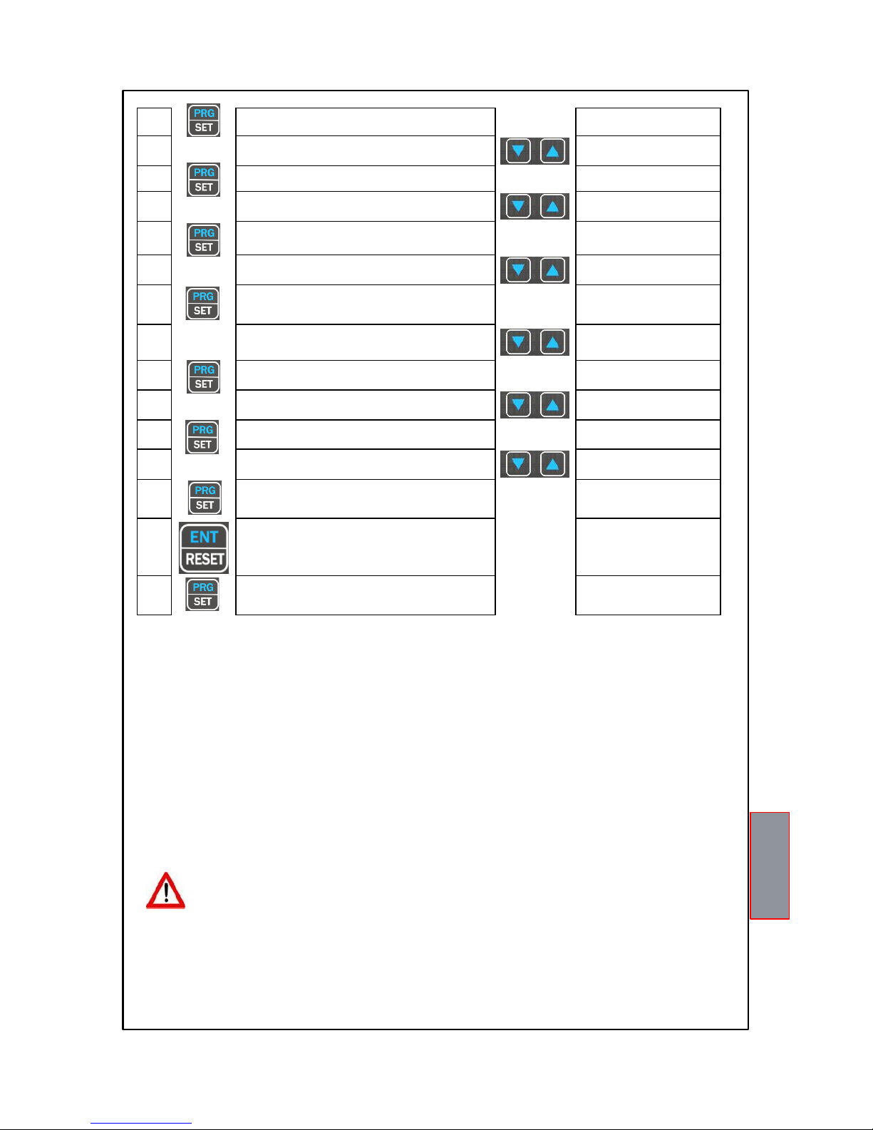
20
HFN (NO) is displayed
The FAN1-FAN2 LEDs flash
Fan cyclic test
for 5 min. every “n” hours
21
Set the desired number of hours
Default NO = function
disabled
22
FCD (NO) is displayed
Fault for quick temperature
of the temperature (°C/sec)
23
Set the desired value
(FCD info on page 19)
Default NO
(function excluded)
24
VOT (NO) is displayed
(VOTING info on page 16)
25
Set 0-1-2-3
Default 0
(function excluded)
26
FLS (ALARM) is displayed
Blinking ALARM LED
(FAIL SAFE info on page 18)
27
Select YES or NO
Default NO
28
FLS (TRIP) is displayed
Blinking TRIP LED
29
Select YES or NO
Default NO
30
FLS (FAULT) is displayed
Blinking FAULT LED
31
Select YES or NO
Default YES
32
END is displayed
End of programming;
33
Press ENT
to save the set data
and exit programming
incorrect programming of the
LED values indicated (note 6)
34
Return to step 1
PROGRAMMING NOTES
1) The MODE key allows reversing the programming steps according to the sequence 24-22-12-1
2) The TEST key allows exiting programming without saving the modified data.
3) After 1 minute's keyboard inactivity programming is abandoned without saving the data.
4) During programming the control unit does not control/protect the monitored machine.
5) At the end of programming the control unit is restarted and the FAULT relay is disabled until the unit is fully
restarted.
6) If pressing ENT, “Err” appears, it means that one of the following mistakes has been made:
ERR ALL. = ALARM ≥ TRIP (CH1-CH2-CH3-CH4-CH5-CH6-CH7-CH8)
ERR FAN = FAN-OFF ≥ FAN-ON. (FAN1 OR FAN2)
The device automatically switches to the programming step of the mistake.
NOTE: EVERY TIME THE CONTROL UNIT PROGRAMMING, WITH CONFIRMATION OF DATA SAVING, THE
VALUES STORED IN T-MAX ARE RESET AT THE TIME OF STORING.
ATTENTION:
We recommend you check the device's programming before starting the device.
The default parameters set by TECSYSTEM might not match your requirements.
Programming the device is the end user's responsibility, the settings of the alarm thresholds and the enabling of
the functions described in this manual must be checked (by a specialized engineer) according to the application
and features of the system the control unit is installed on.
Page 15
15
NT538 WS
All "NT" series control units have linearity of the sensor signal, with a maximum error of 1% of full scale value.
TEMPERATURE SENSORS
Each Pt100 temperature sensor has a white wire and two red ones (CEI 75.8). The figure on page 11 shows the
configuration on the terminal board of the connection cables to the control unit. Each channel can be
independently programmed with two alarm thresholds (alarm and trip).
MEASUREMENT SIGNAL TRANSFER
All the Pt100 measurement signal transfer cables must strictly comply with the following rules:
1. Every Pt100 must be connected with a three-wire cable with a minimum section of 0.35mm² and a maximum of 1 mm².
2. The extension cable must be screened with tinned copper braid with an 80% cover
3. Conductors must be twisted, maximum recommended step 60mm
4. The cable screening must only be earthed with a termination, preferably on the control unit side.
5. The sensors' signal transfer cable must not be near electrical cables, either low or medium-high voltage.
6. The Pt100 cable and the signal transfer cable must be laid in a straight line, without any winding.
7. Any caps used to butt conductors must be crimped properly to avoid false contacts.
NOTE: to install the sensors and signal transferring cable correctly, read the SCS/SENSORS installation rules
manual.
What may happen when installation rules are not complied with.
1) The electrical field propagating from the power line of another circuit couples capacitively with the conductors (in
particular with unscreened cables). The effect of this coupling creates a signal that overlaps the signal transmitted by the
nearby conductors, causing incorrect readings.
2) The variations in magnetic flux in the power lines may induce an electromotive force on the signal transferring cables (in
particular non-twisted cables), that, being a closed circuit, generates a current. This interference current, multiplied by the
circuit resistance, gives a voltage value that overlaps the signal to be transmitted, distorting the sensor measurement.
3) False contacts can alter the signal with the consequent variation in the temperature detected.
In specific cases, when the rules for connecting the Pt100 sensors are not complied with, the following anomalies can
occur between the SCS box and the temperature control unit:
a) incorrect temperature readings, alarms or anomalous tripping
b) mechanical/electrical fault of the Pt100 sensors
c) damage to the Pt100 inputs of the control unit.
TECSYSTEM S.r.l. has designed its own special cable to transfer the measurement signals, CEI-compliant, with all the
protection requirements provided for mod. CT-ES
NOTE: the use of cables not complying with the above might cause possible reading anomalies. It is always
important to take into account that any interference on the signal lines might cause anomalies on the Pt100
inputs (CH1-CH2-CH3-CH4…) or on the sensors themselves.
Page 16
16
NT538 WS
TEMPERATURE SENSOR DIAGNOSTICS
In case of failure or exceeded full scale value of one of the thermometric sensors installed on the machine to protect, the
FAULT relay opens immediately with the relative warning of faulty sensor on the corresponding channel (PT err).
Fcc indicates sensor short-circuited or minimum full scale value of the control unit exceeded -8°C (version 0°÷240°C)
and -48°C (version -40°C÷200°C)
Foc indicates sensor interrupted or maximum full scale value of the control unit exceeded 243°C (version 0°÷240°C)
and 203°C (version -40°C÷200°C)
To eliminate the message and to restore the Fault opening, check the connections of the Pt100 and to replace the faulty
sensor if necessary. In case the minimum/maximum full scale value has been reached, make sure that the environmental
conditions correspond to what is indicated by the control unit.
Note: exceeding the minimum/maximum full scale value can also be caused by interference on the sensor lines; in this
case we recommend that you check:
the correct installation of the sensors and above all of the extension cable (as stated in the paragraph MEASUREMENT
SIGNAL TRANSFER)
the activation of the functions: VOTING (shown below) or FCD (on page 19) must always be operated taking into account
the working conditions of the system.
CAL message display: it appears when damage is found in the measurement circuit. The temperature values displayed
might be incorrect. Return the control unit to TECSYSTEM for repairs.
VOTING FUNCTION
The voting function is derived from the concept of redundancy which consists of the duplication of components of a system
with the intention of increasing reliability.
How the VOTING works?
Taking advantage of the principle indicated we use the probes installed to monitor the operation of the electrical machine,
but at the same time ensure the proper functioning of the probes themselves, discriminating any false alarms (generated
by installation errors or failures).
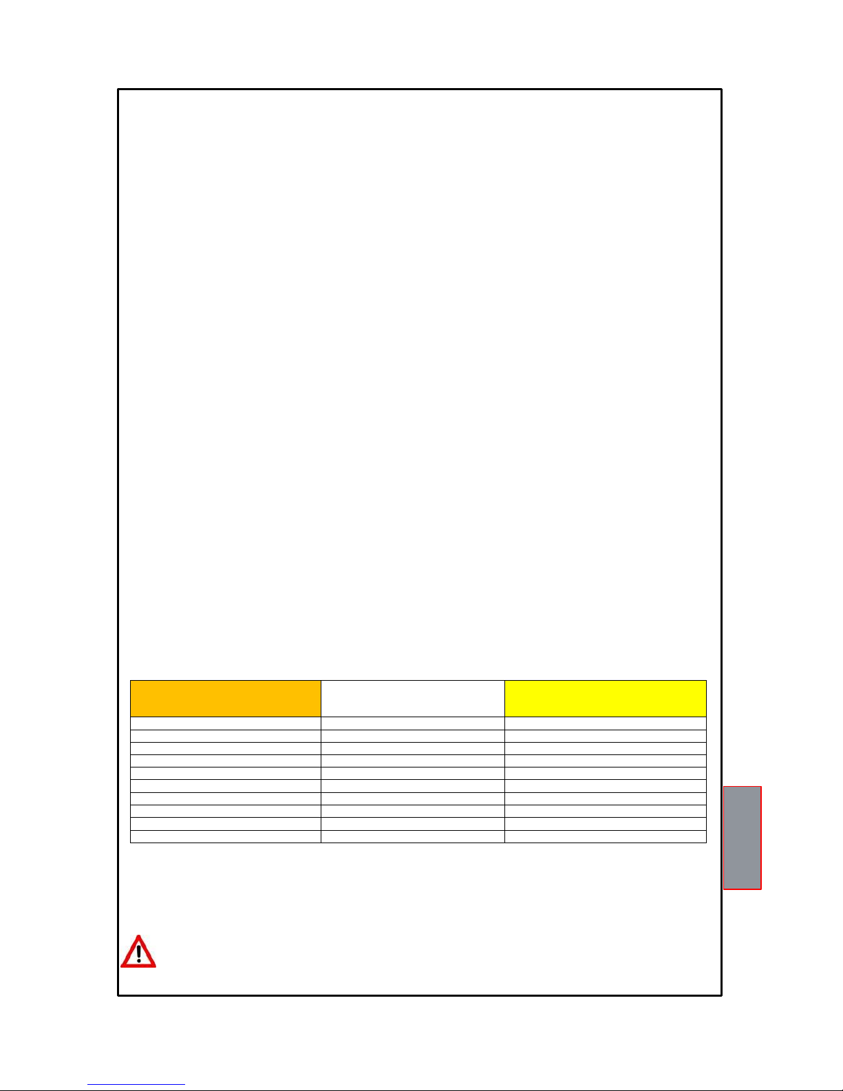
Enabling VOTING can be done by choosing one of three modes of selection "1-2-3" the control unit performs a
comparison of the temperature values measured on the channels monitored, enables switching of the tripping contact
(TRIP) only if it is found the overcoming of the TRIP threshold on at least two channels in the same period T.
Selecting VOTING "NO" function will be disabled.
In the tables, the selection, indicated below you will find the combination of channels with voting active available.
For greater flexibility in two combination we expected channel with voting enabled and others with voting disabled.
Voting enabled: The contact TRIP switches only if at least two channels exceeded TRIP threshold.
Voting disabled: The contact switches when the TRIP single-channel exceeds the threshold of TRIP.
Note: The switching of ALARM signal still exceeded the threshold of alarm on each channel.
To enable Voting read the programming section on pages 13-14.
Attention: To control the transformer correctly from a temperature point of view, enabling the VOTING
function is allowed where the load distributed between the phases of the transformer is adequately balanced.
In addition, any conditions of FAULT: FCC-FCC-FCD on two or more channels, with active voting, can
determine the TRIP contact inhibition.
Selection 1
Selection 2
Selection 3
VOTING ENABLED CH1…..CH3
VOTING ENABLED CH1 …. CH6
VOTING ENABLED CH1 …. CH8
1 1 1 2 2
2
3 3 3
VOTING DISABLED CH4..CH8
4
4
4 5 5 5 6 6 6
VOTING DISABLED CH7..CH8
7 7 7
8
8
8
Page 17

17
NT538 WS
PROGRAMMED DATA DIAGNOSTICS
In case of failure of the internal memory or corruption of programmed data, just after switching on, Ech appears with the
relevant Fault contact signal.
In this case, for safety reasons, the default parameters are loaded automatically (see programming table on pages 13-14).
Eliminate the Ech indication by pressing RESET and run programming to enter the desired values.
Finally switch the unit off and back on to check the memory works correctly, if it is damaged Ech will be displayed again
(send the control unit to TECSYSTEM srl for repairs).
TEMPERATURE DIAGNOSTICS
When one of the temperature sensors senses a temperature 1°C higher than the alarm threshold, 5 seconds later the
ALARM relay switches and the ALARM LED of the affected channel (CHn) lights up.
When the trip temperature limit is exceeded, , 5 seconds later the TRIP relay switches and the TRIP LED of the affected
channel (CHn) lights up.
As soon as the recorded temperature returns to values equal to or lower than the limit set for the ALARM and TRIP relays
switching, these relays de-energise and the corresponding LEDs switch off.
The ALARM and TRIP values are kept in the internal memory: they can be recalled by entering the Vis modes
(programmed parameter display) and modified in PRG (programming) mode.
COOLING FAN CONTROL
The unit NT538 WS has two contacts FAN (FAN1 and FAN2), if properly programmed, can control ON-OFF of fans for
cooling system checked.
The high flexibility of the NT538 WS allows you to select, for each channel, an operation mode for contact management of
FAN1 and FAN2. During the programming of the individual channel, enabled, you will be asked to select one of the
following ways to activate FAN, dedicated to that channel:
YES FAN1+ FAN2 enabled flashing
The selected channel, CHn, will enable the switching of both FAN1 and FAN2 contacts in relation to the ON – OFF
thresholds programmed for FAN1 and FAN2.
YES only FAN1 enabled flashing
The selected channel, CHn, will enable the switching of the FAN1 contact in relation to the ON – OFF thresholds
programmed for FAN1
YES only FAN2 enabled flashing
The selected channel, CHn, will enable the switching of theFAN2 contact in relation to the ON – OFF thresholds
programmed for FAN2.
NO FAN1+ FAN2 disabled flashing
The FAN function on the selected channel, CHn, is disabled. No FAN threshold is associated with the selected channel.
The FAN1 thresholds: (ON - OFF) and FAN2: (ON - OFF) are common for all CHn channels enabled, programmable in
steps 12-19 of programming page 13.
FAN1: (e.g. ON at 70°C - OFF at 60°C)
FAN2: (e.g. ON at 45°C - OFF at 35°C)
The values of ON and OFF can be programmed depending on the range of the device, FAN ON must always be greater by
at least 1 °C since FAN OFF (recommended Δ FAN POWER ON-OFF + 10 ° C).
The FAN 1 / FAN 2 LED light up when the temperature exceeds 1°C the FAN ON threshold, the corresponding relay
switches, and turns off when the temperature goes below 1°C the FAN OFF threshold, the corresponding relay switches.
FAN TEST
It is possible, by programming (HFn), to make sure that the fans are operated for 5 minutes every xxx” hours, regardless
of the temperature values of the columns or the environment (e.g.: with HFn = 001 the fans are activated for 5 minutes
every hour).
This function is designed to periodically check the operation of the fans and of their control equipment.
Setting NO, this function is inhibited.
To enable the HFN function, read the programming section on pages 13-14.
IMPORTANT INFORMATION
Before carrying out the isolation test of the electrical panel the control unit is installed on, disconnect it together
with the sensors from the power supply to prevent it from being seriously damaged.
Page 18

18
NT538 WS
FAIL SAFE FUNCTION
The NT538 WS has n.o selection (contact open ) / n.c (normally closed contact) for ALARM, TRIP and FAULT relays,
programming steps 26 to 31 page 14. The selection of the setting YES/NO introduces functions Fail Safe and No Fail
Safe.
ALARM AND TRIP
Setting NO (NO Fail safe) normally open contacts are in positions 5-7 Alarm and 8-10 Trip, they switch only when limits
are reached preset temperature.
Setting YES (Fail Safe) normally closed contacts are in positions 5-7 Alarm and 8-10 Trip, they switch only when limits
are reached preset temperature or for lack of power.
FAULT
Setting YES (Fail safe) the contact 11-12 is positioned as normally open, switches (closed) when a fault condition is
identified; see section on page 12 alarms and ventilation.
Setting NO (NO Fail safe) the contact 11-12 is positioned as normally closed, switches (open) when a fault condition is
identified; see section on page 12 alarms and ventilation.
Disabling the failsafe function on the fault contact, the unit will no longer be able to report the fault for lack of power. In
this case it is suggested that the enabling of the fail safe on the ALARM contact for the above indication.
NOTE: When the unit is located in one of the methods described below does not monitor heat, also the relay will all be
banned, the FAULT led start blinking.
Vis. display programming.
PRG programming.
Test of the relays.
The FAIL SAFE is temporarily disabled The FAULT relay switches.
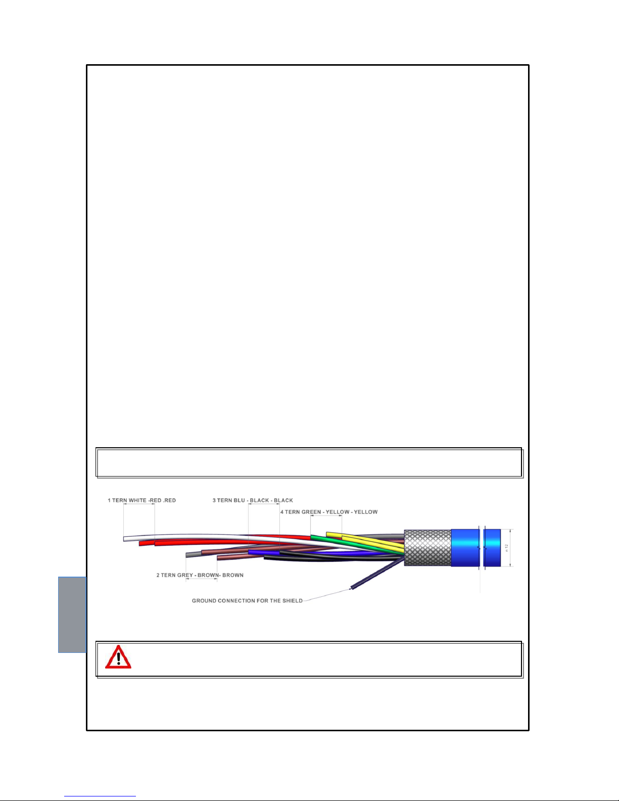
Pt100 EXTENSION CABLE TECHNICAL SPECIFICATIONS
1. Cable 20 x AWG 20/19 Cu/Sn
2. Section 0.55 mm²
3. Flame retardant insulation PVC105
4. CEI 20.35 IEC 332.1 regulations
5. Maximum operating temperature: 90°C
6. Conformation: 4 sets of three twisted and coloured conductors
7. Shield in Cu/Sn
8. Flame retardant PVC sheath
9. External diameter 12mm
10. Standard conformation in 100m coils
Page 19
19
NT538 WS
The NT series equipment boasts an innovative control function combined with the dynamic status of the Pt100 sensor.
Activating FCD, the control unit analyses the increase in temperature ∆T (*) recorded in a second (°C/sec).
Enabling the function, the user can select the value (∆T) from a minimum of 1°C/sec to a maximum of 30°C/ sec. If the
value sensed is higher than the value set by the user, the control unit inhibits the possible activation of the ALARM and
TRIP alarms and switches the FAULT relay (11-12), displaying the message "Fcd fault".
Example: if we set the function to 5°C, FAULT will switch for FCD only if the control unit senses an increase in ∆T of over
5°C in a second on the monitored system.
Setting "no" disables the FCD function.
When a channel is in FAULT for FCD, the relative Alarm and Trip warnings are inhibited on the single channel; therefore
only the over-quick temperature increase is highlighted.
Press Reset to delete the FCD warnings on all channels and reset the FAULT relay.
Possible FCD applications
Identification of a possible induced interference on the Pt100 sensor line
If the installation instructions are not complied with (see page 15), any interference on the Pt100 sensor line can cause
false readings or anomalous alarms.
Setting the FCD function in a temperature range of between 1°C and 10°C (5°C recommended), the effects caused by
false readings can be suppressed and the alarm relay activation can be prevented, as shown above.
Corrective actions: check the installation of the sensor extension cable is in line with the instructions given in the
paragraph on the measurement signal transfer on page 15.
Identification of a sensor fault or faulty connection
In case of a faulty connection or sensor fault, a quick positive or negative variation in temperature might occur, leading to
the system tripping or the alarms of the monitored system to be triggered.
In this specific case we recommend the FCD function to be set in a temperature range of between 10°C and 20°C.
Corrective actions: check the terminals the sensor is connected to are tightened and replace the faulty sensor, if required.
Identification of the electrical motor rotor block
In case of temperature control of the electrical motors, the quick temperature increase might be due to a blocked rotor.
In this specific case we recommend the FCD function to be set in a temperature range of between 20°C and 30°C. This
setting is recommended in order to prevent the FCD function from activating during motor start-up, or where the ΔT/sec.
increase varies quickly.
(*) The ΔT value shows the temperature range for each second.
NOTE: you should not enable the FCD function with active VOTING.
FCD FUNCTION
NT538 WS WI-FI CONNECTION
The NT538 WS control unit has a built-in WEB SERVER that is accessible via Wi-Fi connection.
What is needed to access the NT538 WS control unit?
To access the web server a device with a Wi-Fi connection and an Internet browser is needed.
How to connect on the first start? “Access Point” mode :
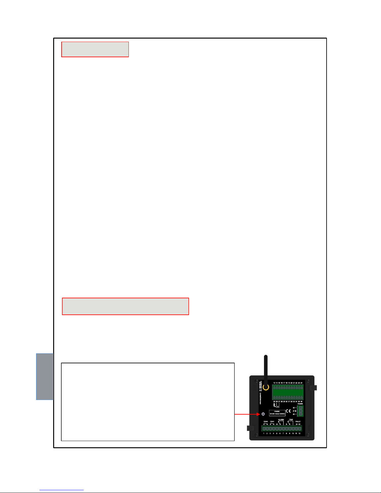
Power the control unit by keeping the button on the back pressed
for approximately 5 seconds.
NOTE: Access point key
The access point key allows the user to temporarily access the web server in the
"Access Point" mode, forcing operation with the IP address 192.168.8.8.
How it works:
With the control unit off, keep the access point button pressed, then power the
device and release the button after approximately 5 seconds
Page 20
20
NT538 WS
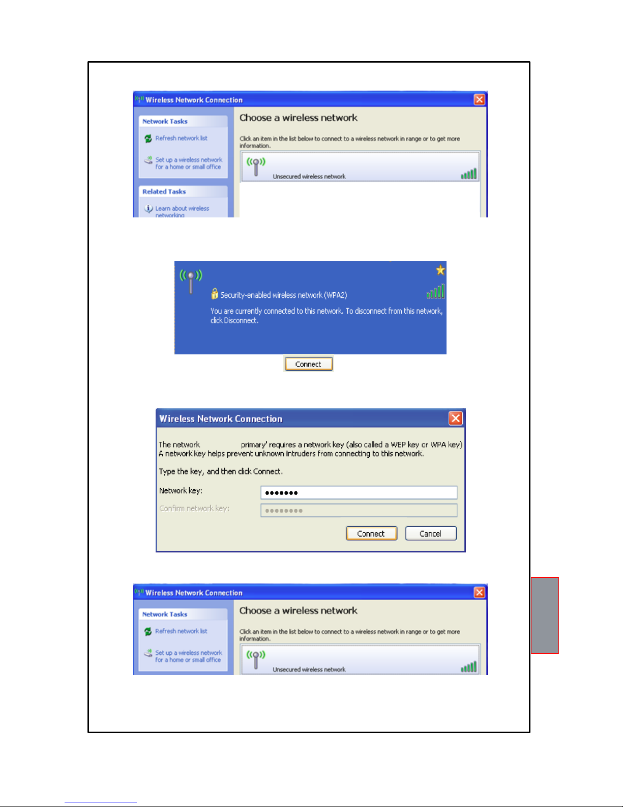
Launch the search for Wi-Fi networks from your device (PC, Smartphone or Tablet).
NOTE: the name of the network to connect to consists of: TECSYSTEM followed by the serial number S/N of the device
and the year of production (18 = 2018), valuesshown on the identification label of the product purchased.
Select the TECSYSTEM (S/N + YEAR) network.
Click on CONNECT
The TECSYSTEM network requires the insertion of a digital network key: TECSYSTEM in the network key window, repeat
the operation in the network key confirmation window.
Click on CONNECT
Once the connection is established, your device will indicate Connected TECSYSTEM.
NOTE: Connecting to the TECSYSTEM network will result in automatic disconnection from other networks; for devices such
as Smartphones or Tablets it may be necessary to disable the data connection.
Having connected to the TECSYSTEM network (S/N + YEAR) open your browser program and type in the address
192.168.8.8, that follows on page 21.
TECSYSTEM (S/N + YEAR)
TECSYSTEM (S/N + YEAR)
TECSYSTEM (S/N + YEAR)
TECSYSTEM
Page 21
21
NT538 WS
TECSYSTEM WEB SERVER
Through the Wi-Fi connection, the TECSYSTEM WEB SERVER interface allows the user to access all the information
present on the web server integrated in the NT538 WS.
To take full advantage of the product features it is advisable to connect the NT538 WS to a Wi-Fi network (STATION mode).
The Wi-Fi connection will allow you to manage multiple control units under a single network and to control them from any
device connected to the network. The NTP Server setting (time.google.com or other), see STATION options page 24, will
allow automatic updating of date and time.
The STATION or ACCESS POINT operating mode is shown in the footer on the HOME screen:
WI-FI CONNECTED TO (NETWORK NAME) - MODBUS RUNNING (STATION)
WI-FI DISCONNECTED - MODBUS RUNNING (ACCESS POINT)
NOTICE: when the control unit is not connected as a station but as an access point, the recordings present in the device will
follow a chronological order but will not have the date/time data available. Accessing the "Options" page it will be possible to
set the date/time data manually, see page 24.
NOTE: in the Access point functionality to avoid loss of date and time, due to power failure, it is advisable to connect the
device via UPS power supply. Failure to set the clock and calendar is indicated by a POP UP window.
The data collected on the web server is divided into 5 screens:
Presentation screen
Home screen
Settings screen
Graphics screen
Event log screen
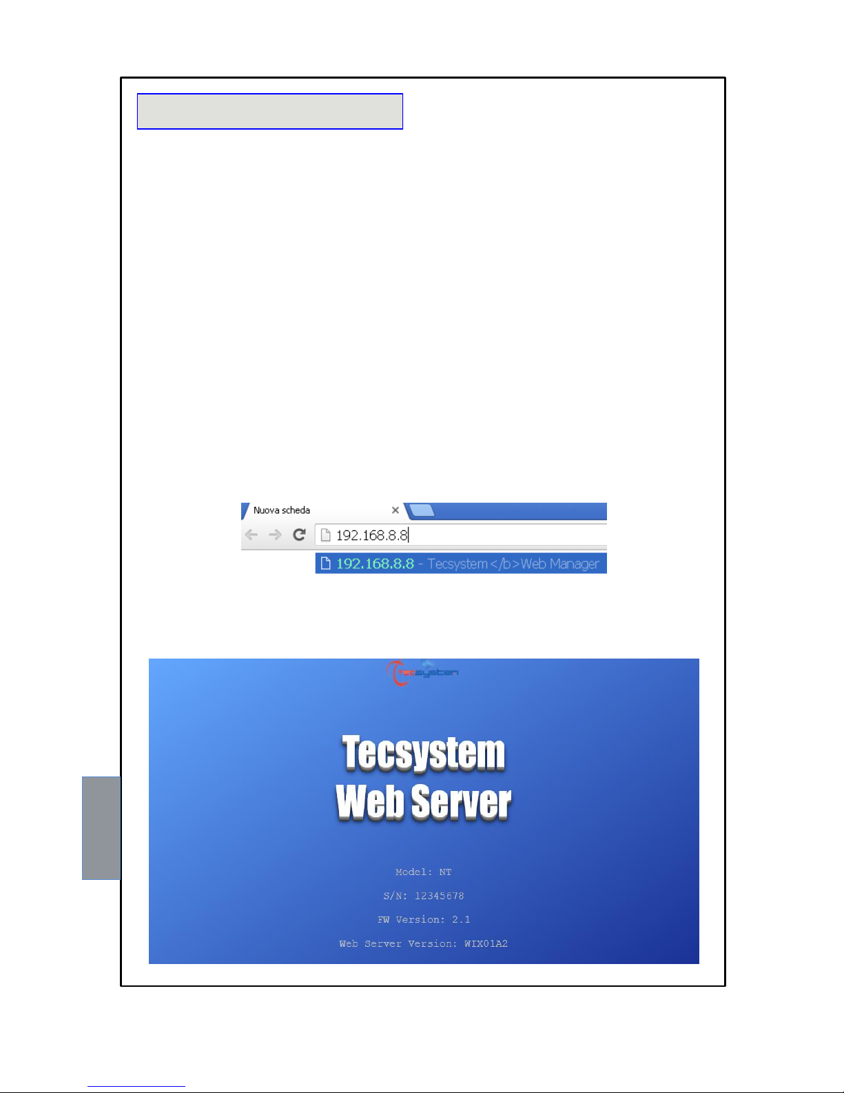
Open your browser and enter the address: 192.168.8.8
Select 192.168.8.8 Tecsystem Web Server, press ENTER.
The web manager's presentation page will appear for a few seconds, showing the model of the control unit, the serial number
of the device and the year of production, its firmware version and the web server version.
(Device serial number, firmware version and web server version)
(measured temperatures and channel status)
(NT538 device programming and web manager settings)
(display of temperature graphs and CHn channel data export)
(display and events export)
Page 22
22
NT538 WS
WEB SERVER MANAGEMENT BAR
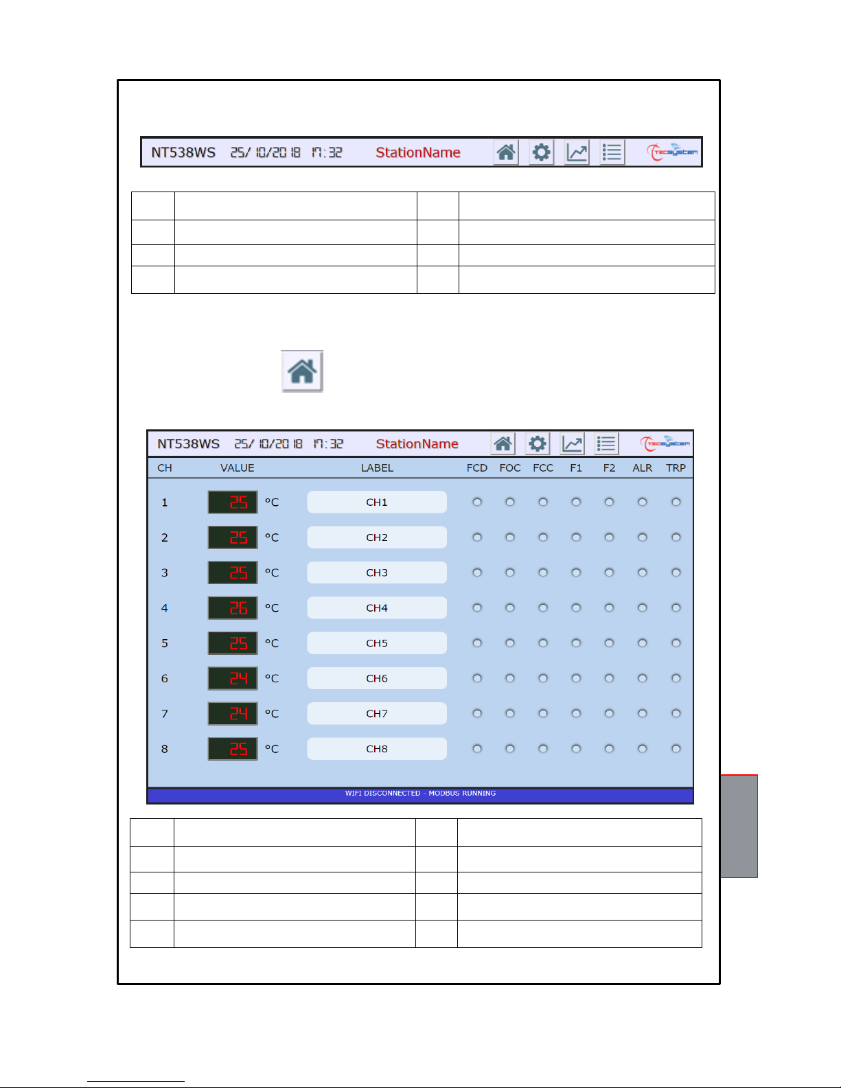
The web server management bar allows the user to identify the cabin and to select the various screens.
The following information is shown in the management bar:
1
Control unit model
5
HOME screen selection key
2
Reference date
6
SETTINGS screen selection key
3
Reference time
7
GRAPHICS screen selection key
4
Station Name or monitored cabin (*)
8
EVENT LOG screen selection key
(*) The Station Name indication can be customised by the user in the options- labels settings screen, see page 25.
Pressing the selection keys 5-6-7-8 it is possible to access the various screens; the web manager will display only
one screen at a time.
1
2
3
4
5
6
7
8
HOME SCREEN
The HOME screen shows the operating status of each channel, i.e.: the temperature detected by each channel, the FCDFOC-FCC sensor fault indications, activation of the F1-F2-ALARM-TRIP alarms.
1
Channel indication CH1-CH2-CH3-CH4-CH5CH6-CH7-CH8
6
FCC signal ON red LED
2
Channel temperature CH1-CH2-CH3-CH4-CH5CH6-CH7-CH8
7
F1 signal ON yellow LED (FAN1)
3
Channel reference label (*)
8
F2 signal ON yellow LED (FAN2)
4
FCD signal ON red LED
9
ALR signal ON red LED (ALARM)
5
FOC signal ON red LED
10
TRP signal ON red LED (TRIP)
(*) the label indication can be customised by the user in the options – labels settings screen, see page 25.
1
2
3
4
5
6
7
8
9
10
Page 23
23
NT538 WS
SETTINGS SCREEN
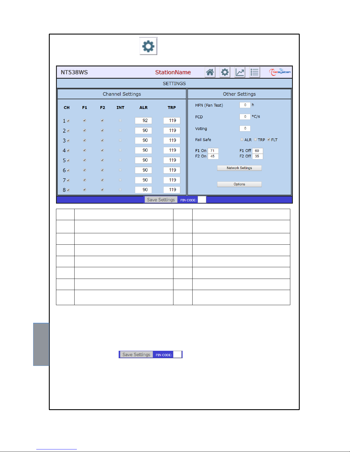
In the settings screen it is possible to modify the programming of the NT538 WS control unit.
1
Channel reference and enabling
CH1-CH2-CH3-CH4-CH5-CH6-CH7-CH8
9
Voting setting box: (0-NO) (1-2-3)
See the voting on page 16.
2
Channel FAN 1 Enabling
CH1-CH2-CH3-CH4-CH5-CH6-CH7-CH8
10
Enabling of FAILSAFE FUNCTION,
Relay: ALARM-TRIP-FAULT
3
Channel FAN 2 Enabling
CH1-CH2-CH3-CH4-CH5-CH6-CH7-CH8
11
FAN 1 limit programming boxes
On and Off (from 0°C to 240°C)
4
INTELLIFAN FUNCTION enabling
Not available for NT538 WS
12
FAN 2 limit programming boxes
On and Off (from 0°C to 240°C)
5
ALARM limit programming box
(from 0°C to 239°C)
13
NETWORK SETTINGS key
6
TRIP limit programming box
(from 1°C to 240°C)
14
Option Key
7
HFN setting box (from 0h to 200h)
0= function disabled
15
SAVE SETTINGS key
8
FCD setting box (from 0°C to 30°C)
0= function disabled
16 PIN CODE (*)
As for the panel programming also for programming through WEB SERVER it is necessary to follow these rules:
AL. = ALARM ≥ TRIP
FAN = FAN-OFF ≥ FAN-ON. (FAN1 OR FAN2)
INT = INT FAN-OFF ≥ FAN-ON (FAN1) DELTA <10°C
The cells of the editable values are accessible in white, the grey cells are not accessible. The programming limits of the
monitored parameters are shown in the table above.
SAVE SETTINGS key
After entering the PIN CODE, default 00000, pressing the SAVE SETTINGS button the user updates the programming data
of the NT538 WS device. The control unit will lose the connection for a few seconds, the device will start after which the new
values will be available on the updated screen.
Incorrect programming of the device will result in the display of an error POP UP window with the relative signalling; the data
update will not be processed.
(*) Note: PIN CODE settings and operation at page 28.
1
2
3
4
5
6
7
8
9
10
11
12
13
14
15
16
Page 24
24
NT538 WS
ATTENTION:
We recommend you check the device's programming before starting the device.
The default parameters set by TECSYSTEM might not match your requirements.
Programming the device is the end user's responsibility, the settings of the alarm thresholds and the enabling of
the functions described in this manual must be checked (by a specialized engineer) according to the application
and features of the system the control unit is installed on.
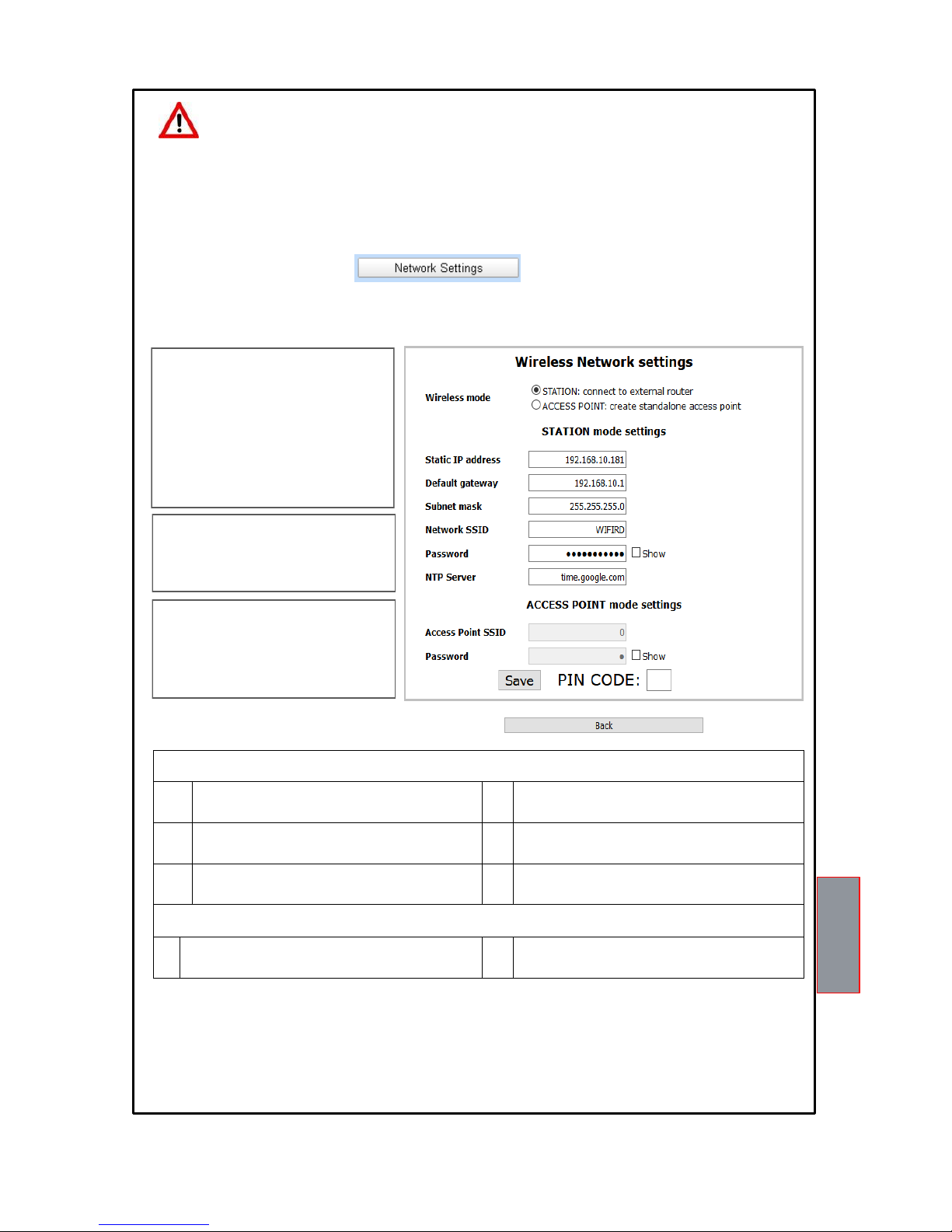
NETWORK SETTINGS key
Pressing the NETWORK SETTINGS button the user accesses the Wireless network setting screen. In this screen the user
can select the STATION or ACCESS POINT operating mode and set the network parameters.
WIRELESS MODE
it allows the user to select the operating
mode.
STATION: the web server is connected via
WI-FI to a pre-established network.
ACCESS POINT: the device works in the
indicated mode, creating its own
independent Wi-Fi network.
STATION MODE SETTINGS
Setting of the defined network parameters to
which the control unit is connected.
ACCESS POINT MODE SETTINGS
Setting of network parameters: SSID
network name) and Password of the
network to which the control unit is
connected.
1 Selection STATION mode settings
2
Static IP address
5
Wi-Fi network name
(Wi-Fi network on which to connect the device)
3
Default gateway
6
Wi-Fi network password
(SHOW for password verification)
4
Subnet mask
7
Server NTP address
(automatic time and date update)
1 Selection ACCESS POINT mode settings
8
Access Point SSID (default TECSYSTEM)
(network name modification)
9
Password (default TECSYSTEM)
(SHOW for password verification)
After entering the PIN CODE, default 00000, Press SAVE to save the set values. A POP UP window will confirm the correct
saving of data.
Press BACK to return to the previous screen.
(*) Note: PIN CODE settings and operation at page 28.
1
2
3
4
5
6
7
8
9
NOTE: For information / clarifications regarding the Wifi
network connection, contact your IT MANAGER
Page 25
25
NT538 WS
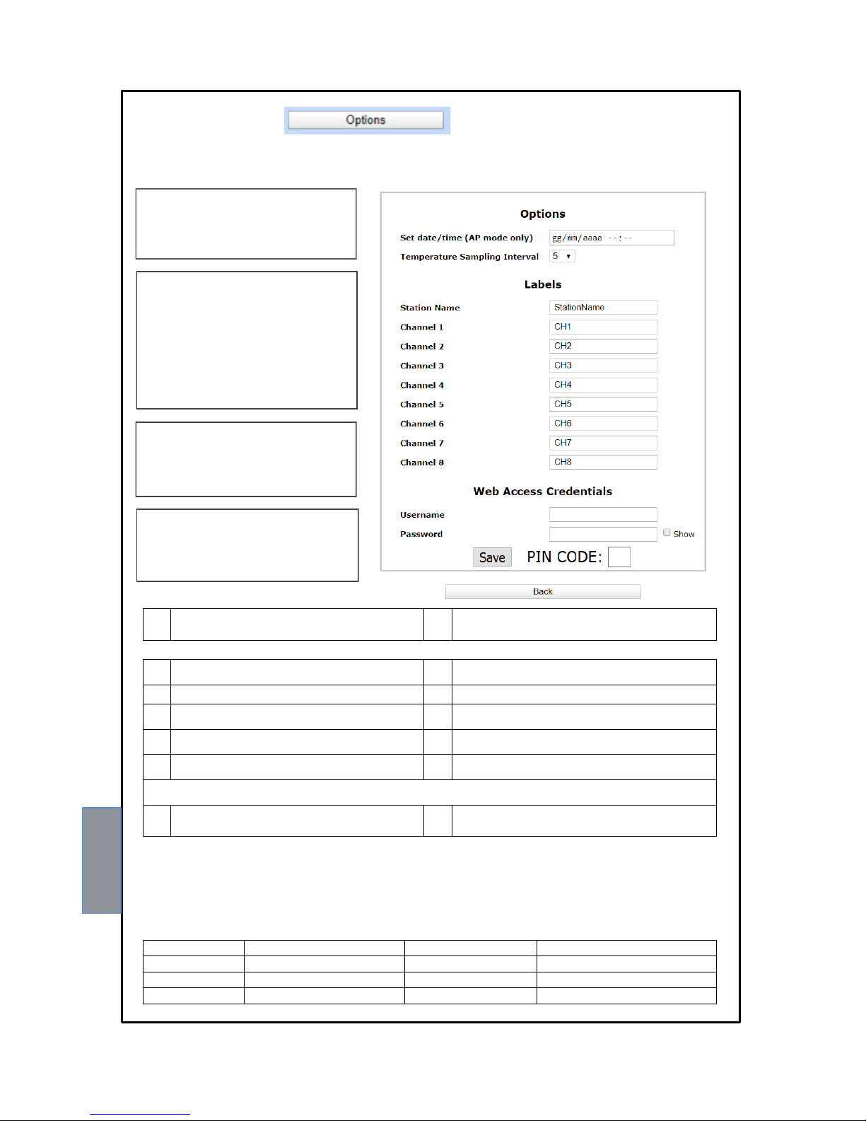
OPTIONS key
Pressing the OPTIONS button accesses the options screen. On this page it is possible to: set the date and time in the Access
Point mode, select the sampling interval, customise the labels (labels) station and channels and set the username and
password useful to access the web server.
The Web Access Credentials setting
It is used to set username and a password.
Upon each log in to the web server, a POPUP credential window will appear.
Set data/time (AP mode) allows the user to
manually set the date and time in AP mode.
This information is essential for correct
operation of the control unit.
Temperature Sampling Interval.
The sampling interval represents the waiting
time between one recording and the next. In
the timing table, below, for each selection,
the number of days/months that the NT538
WS device is able to memorise is
represented. Once the indicated value has
been exceeded, the data will be overwritten
and therefore no longer available.
Labels
The labels are used to customise, as
desired, identification of the control unit and
of the individual channel.
1
Date and time setting in mode
Access point mode
2
Selection of sampling range
every (5-10-15-20-30-60) minutes
Labels
3
Station Name label
8
Label channel 5
4
Label channel 1
9
Label channel 6
5
Label channel 2
10
Label channel 7
6
Label channel 3
11
Label channel 8
7
Label channel 4
Web Access Credentials (setting of Username and Password for Web Server access)
12
Username
13
Password (SHOW for password
verification)
Selection
Duration in days/months
Selection
Duration in days/months
5 min.
60 days / 2 months
20 min.
243 days / 8 months
10 min.
121 days / 4 months
30 min.
365 days / 12 months
15 min.
182 days / 6 months
60 min.
730 days / 24 months
Timing table
After entering the PIN CODE, default 00000, Press SAVE to save the set values. A POP UP window will confirm the
correct saving of data.
Press BACK to return to the previous screen.
(*) Note: PIN CODE settings and operation at page 28.
1 2 3
4 5 6 7 8 9 10
11
12
13
Page 26
26
NT538 WS
GRAPHICS SCREEN
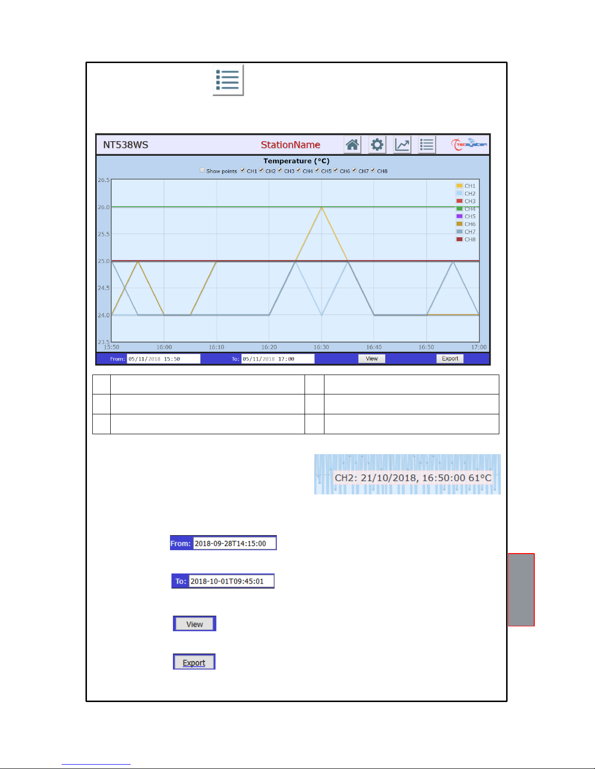
The Graphics screen allows the user to view the temperature trend of the enabled channels, CH1-CH2-CH3-CH4-CH5CH6-CH7-CH8, graphic view notes on page 28. Data saving can be programmed according to user needs by changing the
sampling range, options screen on page 25.
1
Recording points display flag
4
Data availability A yy/mm/dd Time: hh/mm/ss
2
CHn channel enabling flag
5
View key
3
Data availability DA yy/mm/dd Time: hh/mm/ss
6
Export key
EXPORT button
By pressing the EXPORT button, all the temperature values recorded according to the FROM/TO selections can be
downloaded in CSV format (text file). Export notes CSV file on page 28.
VIEW button
Pressing the VIEW button will update the chart according to the dates selected FROM/TO.
FROM box
It allows the user to select the period of graphic display by changing the data availability from yy/mm/dd - Time: hh/mm/ss
TO box
It allows the user to select the period of graphic display by changing the data availability to yy/mm/dd - Time: hh/mm/ss
CH channel selection flag
Recording points display flag
Enabling the recording points display flag it will be possible to
identify each recording in the graph. Clicking on the individual
point will show the information of: channel, date, time and
recorded temperature value.
Enable / disable the graphic display of the individual CHn channel.
1 2 3 4 5
6
Page 27
27
NT538 WS
EVENT LOG SCREEN
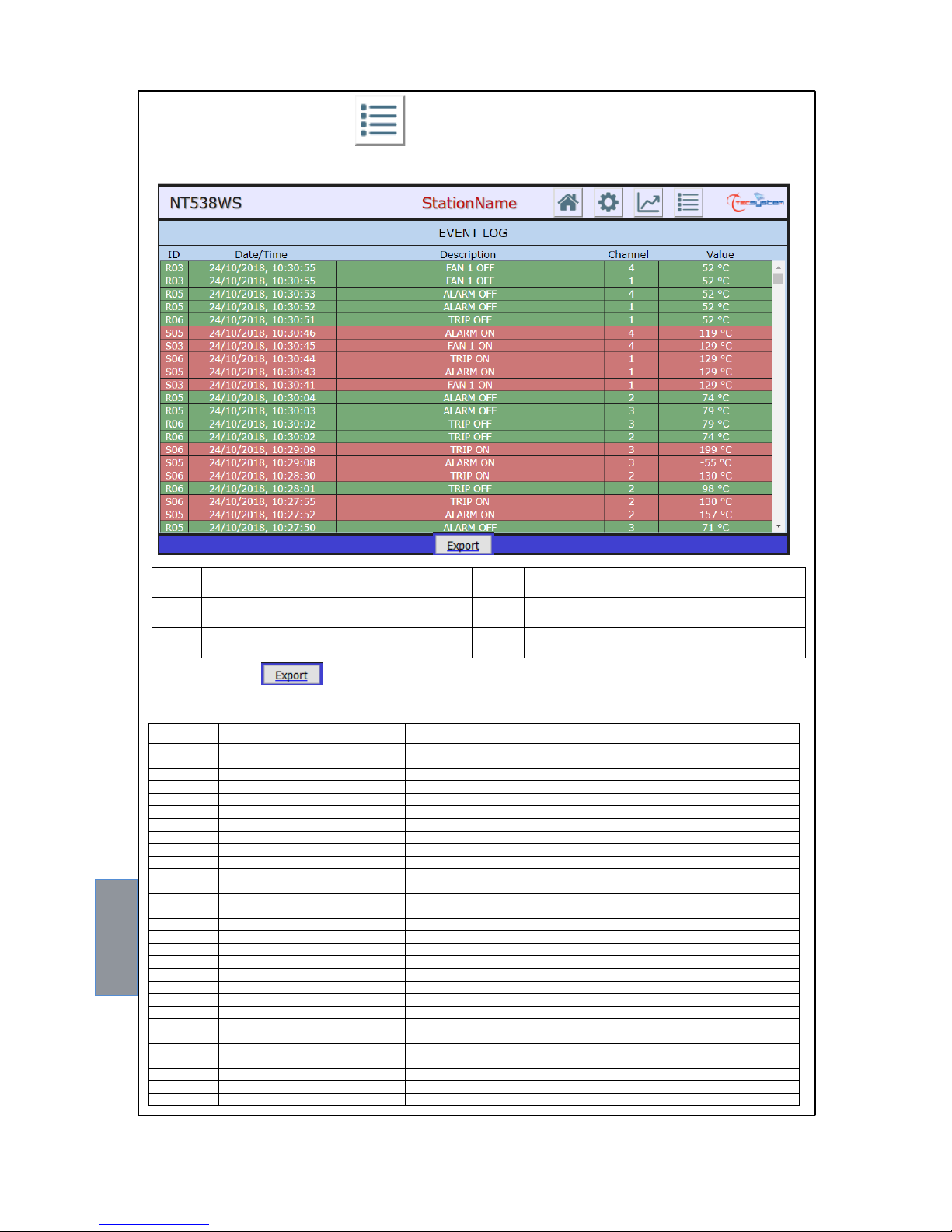
The Event log screen is used to quickly obtain an immediate overview of the events recorded by the control unit. Each event
is identified with ID code, see event ID table.
1
Events ID (see ID events table)
4
Event channel numbering
2
Date and time
5
Temperature value recorded
3
Description
6
Export key
Pressing the EXPORT button results in downloading of all the events recorded in CSV format, see notes on page 28.
ID events table
EXPORT key
3 4 5 1 2
6
Code
Message
Description
I00
system restarted
web server start
I01
real time clock sync
Automatic setting date and time via sync server
I02
login successful
web server access
I03
web server in STATION mode start
Start mode web server in STATION
I04
Wi-Fi Access point started
web server in ACCESS POINT mode start
I05
Wi-Fi connected
Web server connected to the Wi-Fi network
I06
Setting saved
Saving of web server network parameters
I07
temperature log saved to csv
saving of the csv file temperatures
I08
event log saved csv
saving of the csv file events log
W00
Wi-Fi not connected
A Wi-Fi disconnected from the network
W01
Real time clock set to last saved
Reset date and time, automatic, from the last saving
W02
Real time clock manually set
Manual date and time setting
W03
diagnostic button pressed
the access point key has been pressed
R00
Fcc off
FCC OFF fault signal on CHn channel identified
R01
Foc off
FOC OFF fault signal on CHn channel identified
R02
Fcd off
FCD OFF fault signal on CHn channel identified
R03
Fan1off
FAN1 OFF switch off signal on CHn channel identified
R04
Fan2off
FAN2 OFF switch off signal on CHn channel identified
R05
Alarm off
ALARM OFF switch off signal on CHn channel identified
R06
Trip off
TRIP OFF switch off signal on CHn channel identified
S00
Fcc on
FCC ON fault signal on CHn channel identified
S01
Foc on
FOC ON fault signal on CHn channel identified
S02
Fcd on
FCD ON fault signal on CHn channel identified
S03
Fan1on
FAN1 ON activation signal on CHn channel identified
S04
Fan2on
FAN2 ON activation signal on CHn channel identified
S05
Alarm on
ALARM ON activation signal on CHn channel identified
S06
Trip on
TRIP ON activation signal on CHn channel identified
E00
Modbus error
Modbus error signal
E01
Internal error
Signal internal web server error
Page 28
28
NT538 WS
PIN CODE
PIN CODE is a five-digits code, programmable by the user, useful to confirm the user's intention to modify the device
programming or network settings. It represents the key for changing the parameters reserved for the system operator
manager, limiting any risks of unauthorized modifications or programming errors.
Without the PIN CODE, or with the wrong PIN, device programming cannot be changed.
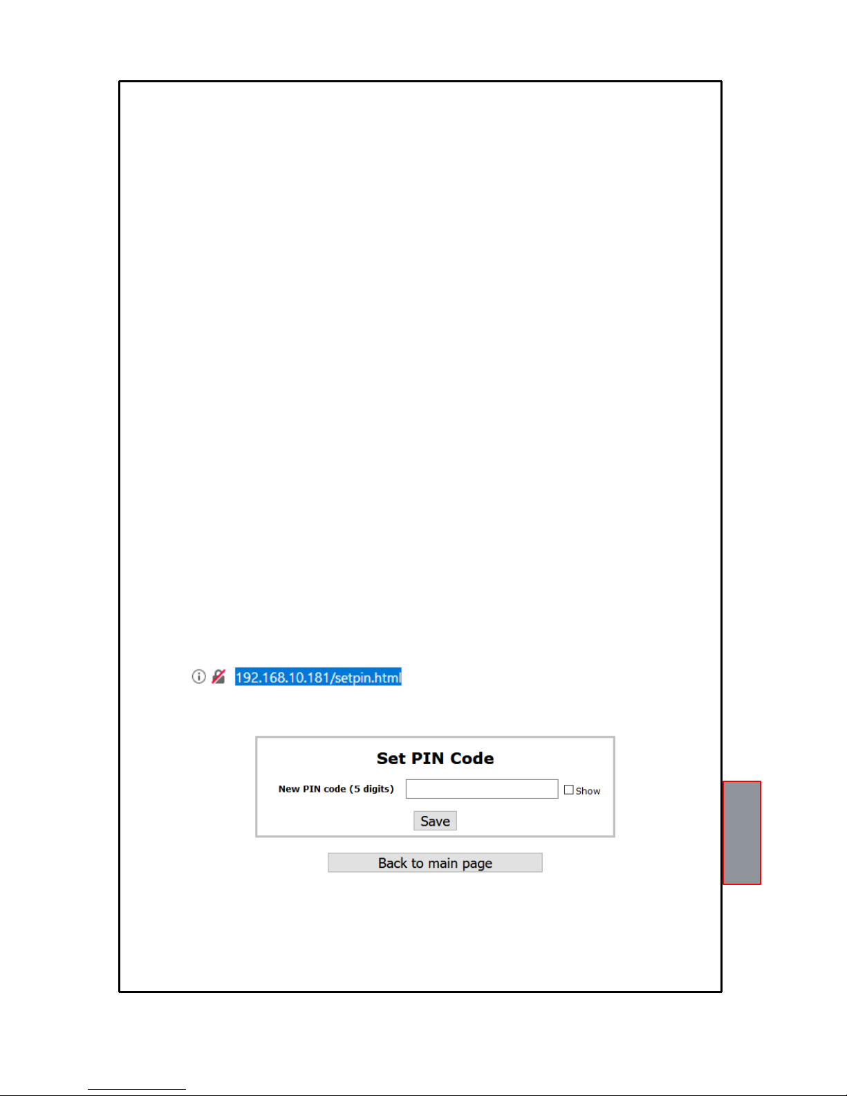
How to change the PIN CODE:
Switch off the device and switch it on again keeping the access point key, placed on the back, press it for at least
2 seconds.
Connect to the device and type, on the browser screen, the IP address http: // XXX. XXX.XX.XXX /setpin.html
Example:
Press ENTER, the SET PIN CODE screen will open.
Type the new pin code desired, in the appropriate box, maximum 5 numbers (SHOW to display the PIN CODE).
Press SAVE to save the pin. A POP UP window will confirm the correct saving.
PIN CODE default setting: 00000
Press BACK to main page to return to the main screen.
GRAPHIC VIEW NOTES
When the graphic page opens, the last 300 recorded points are displayed by default; if there are less than 300 points in
memory, the available ones are displayed.
If you set the "from” – “ to "dates the chart view graphic is " zoomed" and shows only the points that fall within the specified
selected dates.
In the case of the "from" - "to" interval are outside of the default display "300 points" (but in any case within the data
availability interval, because the two input fields do not allow the insertion dates outside of those available), the display
starts from the date "from" and continues towards "to" but only up to a maximum of 1500 points.
When the 1500 points are exceeded, a message will be signaled to the user to warn that the displayed interval may be
lower than the one requested.
EXPORT NOTES CSV FILE
Following the exporting of the CSV file for EVENT LOG all the recorded events are exported.
Following the exporting of the CSV file recorded TEMPERATURE VALUE, the last 300 recorded points will be contained
in the file; if there are less than 300 points in memory the available data are exported.
In the case of "from" - "to" dates are set, in the graphic, the temperature values exported will only be the points that fall
within the specified selected dates. If the "from" - "to" interval is outside the default display "300 points" (but in any case
within the data availability interval, because the two input fields do not allow to set dates outside those available) all the
points recorded will be include in the exported file.
(IP ADDRESS)
Page 29
29
NT538 WS
The Product purchased is covered by the manufacturer's or seller's warranty at the terms and conditions set forth in the
"Tecsystem s.r.l's General Conditions of Sale", available at www.tecsystem.it and / or purchase agreement.
The warranty is considered valid only when the product is damaged by causes attributable to TECSYSTEM srl, such as
manufacturing or components defects.
The warranty is invalid if the Product proves to have been tampered with / modified or incorrectly connected and causing
voltages outside the set limits and does not comply with the technical data for use and assembly, as described in this
instruction manual.
The warranty is always ex Corsico as stated in the "General Conditions of Sale".
WARRANTY CONDITIONS
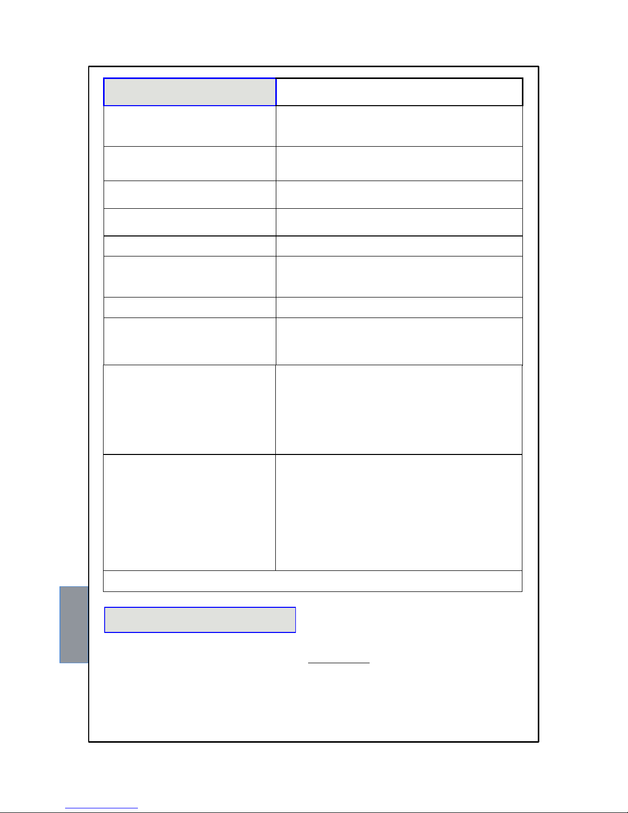
TROUBLESHOOTING
CAUSES AND SOLUTIONS
The control unit does not switch on and the
supply to terminals 40-42 is correct.
Check that: the connector is firmly inserted in its place, the connection
wires are tight and that there are no obvious signs of burns on the
connectors. Turn off the power supply and carry out the above
instructions, restore the voltage.
One of the channels is in FAULT for FOC/FCC
Check the connections of the Pt100 sensors, check the indications in
the paragraphs: measurement signal transfer and diagnostics of
thermometric sensors page14-15.
When turned on, the indication "ECH" appears
A strong disturbance has damaged the memory data. See the
paragraph for programmed data diagnostics on page 16.
All the Pt100 sensors are in FCC.
Incorrect sensor connection, the terminal block has been inserted
upside down. Check the connections and the terminal board.
The temperature shown by one or more
channels is wrong.
Contact the TECSYSTEM Technical Department.
Sudden trip of the main switch. The temperature
is on standard levels. Just one channel has
caused the trip.
Check the temperatures recorded in T-MAX, check the instructions
given in the paragraphs: measurement signal transfer and diagnostics
of thermometric sensors page16. Activate the FCD function.
FCD warning
See the FCD function on page 19.
During the operation of the web server it is not
possible to display the date and time and also
the graphics screen does not work.
In the Access point mode select settings/Options and enter the date
and time in the Set data/time (AP mode) box
In Station mode, select settings/Networking and enter
time.google.com in the Server NTP box
The web server has been set in Access Point
mode but the network cannot be identified.
With the control unit off, keep the access point button pressed, then
power the device and release the button after approximately 5
seconds. The TECSYSTEM network (S/N + YEAR) will appear and
connect to the network using the TECSYSTEM password. Open your
browser and type in the address 192.168.8.8 use the web server bar
to enter the Settings page, press the Network setting button and
check: the ACCESS POINT selection, the settings SSID and
Password, press save.
The web server has been set in Station mode
but the web server cannot be accessed.
With the aid of a device with a Wi-Fi connection (PC, Smartphone or
Tablet) with the control unit off, keep the access point button pressed,
then power the device, and release the key after approximately 5
seconds. Launch the search for the Wi-Fi network from your device.
The TECSYSTEM network will appear (S/N + YEAR), connect to the
network using the TECSYSTEM password. Open your browser and
type in the address 192.168.8.8, use the web server bar to enter the
Settings, page, press the Network setting button and check:
STATION selection, settings: IP – GATEWAY -SUBNET MASK – NET
WORK SSID – PASSWORD,
press save.
Contact the TECSYSTEM Technical Department if the problem persists.
Page 30
30
NT538 WS
TECHNICAL INFORMATION: [email protected]
COMMERCIAL INFORMATION : [email protected]
USEFUL CONTACTS
European directives 2012/19/EC (WEEE) and 2011/65/EC (RoHS) have been approved to reduce electrical and electronic
waste and to promote the recycling and reuse of the materials and components of said equipment, cutting down on the
disposal of the residues and harmful components of electrical and electronic materials.
All the electrical and electronic equipment supplied after 13 August 2005 is marked with this symbol, pursuant to
European directive 2002/96/EEC on electrical and electronic waste (WEEE). Any electrical or electronic equipment
marked with this symbol must be disposed of separately from normal domestic waste.
Returning of used electrical appliances: contact TECSYSTEM or the TECSYSTEM agent to receive information on correct
disposal of the appliances.
TECSYSTEM is aware of the impact its products have on the environment and asks its customers active support in the
correct and environmentally-friendly disposal of its devices.
EQUIPMENT DISPOSAL
 Loading...