

http://www.tecsystem.it
INSTRUCTION MANUAL
TECSYSTEM S.r.l.
20094 Corsico (MI)
Tel.: +39-024581861
Fax: +39-0248600783
NT538
TECSYSTEM S.r.l ®
R. 1.3 07/09/12
NT538

2
NT538
TECSYSTEM S.r.l ®
INNOVATIONS INTRODUCED WITH THE NT538
1. New hardware and software for a further improvement of immunity to disturbances.
2. Reading rate increasing, indispensable for applications where fast temperature
variations must be monitored.
3. Intelligent control of alarm detecting relays which is able to exclude possible
overtemperatures caused by an external disturbance without causing working problems or manual reset conditions.
4. Detecting of possible corruption of data stored in the memory (Ech) and default
value reset for security.
5. Storage in T. Max mode of possible alarms occurred from last reset and recording of
possible sensor failures.
6. Error detecting in case of wrong programming with specific indication of the wrong
value couple.
7. Possibility to return to previous programming step for a faster value modification.
8. SCAN display mode to see, in sequence, the temperature and the state of the
alarms for all channels
9. 8 channels with two programmable thresholds in an independent way.
10 Fan contact to check a cooling system.
11. More compact sizes compared with T538 version1.
12. Options with serial output to control the expansion module such as:
a) EXT 4.20-8: module with 4-20 mA outputs for each channel
b) EXT RL-8: module with 2 relays (alarm and trip) for each channel
c) EXT RS485 Modbus: module for connection on a Modbus network
13. Possibility to connect many expansion module on serial output in order
to have many expanding options simultaneously.

3
NT538
TECSYSTEM S.r.l ®
1) TECHNICAL SPECIFICATIONS
POWER SUPPLY
• Rated values 24-240 Vac-dc
• Highest tolerable values 20-270 Vac-dc
• Vdc with reversible polarity Vdc
COMMUNICATION
• option
INPUTS
• 8 inputs RTD Pt100—3 wires
• Removable rear terminals
• Input channels protected against electro-
magnetic noises and spikes
• Sensor length cable compensation up to
500 m (1 mm² )
OUTPUTS
• 2 alarm relays (ALARM-TRIP)
• 1 alarm relay for fan control (FAN)
• 1 alarm for sensor fault or working anom-
aly (FAULT)
• Outputs contacts capacity: 5A-250V ac
resistive.
TESTS AND PERFORMANCES
• Assembling in accordance with CE rules
• Protection against electrical noises CEI
-EN50081-2/50082-2
• Dielectric strength 2500 Vac for 1 minute
from relays to sensors, relays to power
supply, power supply to sensors
• Accuracy ± 1% full scale value ± 1 digit
• Ambient operating temperature from –20
°C to +60°C
• Humidity 90% no-condensing
• housing NORYL 94V0
• Frontal in polycarbonate IP65
• Absorption 3VA
• Data storage 10 years minimum
• Digital linearity of sensor signal
• Self-diagnosis circuit
• Option protection treatment of elec-
tronic part
• Vibration test IEC 68-2-6
Amplitude ± 1 mm from 2Hz a 13.2Hz
Acceleration ± 0.7G from 13.2Hz to
100Hz.
• (*) Seismic test according to
IEEE 344-1.987
*Cross reference T154 for constructive analogy.
DISPLAYING AND DATA MANAGEMENT
• 1 display 13mm high with 3 digit for displaying temperatures and messages
• 8 leds to show selected channel
• 4 leds to display the state of the alarms
for selected channel
• Temperature monitoring from
0°C to 240°C
• 2 alarm thresholds (alarm/trip) for each
channel
• 2 ON-OFF thresholds for fan control
• Sensors diagnostic (Fcc-Foc)
• Data storage diagnostic (Ech)
• Programming access through front key
• Automatic output from programming cycle
after 1 minute of no-operation
• Wrong programming automatic display
• Possibility of setting automatic channels
scanning, hottest channel, manual scanning
• Maximum reached temperatures, alarm
storage and sensor fault.
• Frontal alarm reset push button
DIMENSIONS
• 100 x 100 mm-DIN43700– depth 140
mm (terminal box included)
• Panel cut-out 92 x 92 mm

4
NT538
TECSYSTEM S.r.l ®
2) MOUNTING
Make a hole in the panel sheet with dimensions 92x92 mm.
Firmly tighten the device with the enclosed fixing blocks.
3) POWER SUPPLY
NT538 control device has an UNIVERSAL supply, i.e. it can be indifferently fed from 24 to
240 Vac-dc, regardless of polarities in Vdc.
This peculiarity is obtained using a new-concept and new-designed tested feeder, which
relieves the technician of each concern for the correct supply Vac or Vdc.
To terminal 41 must always be connected the ground.
When the control device is directly fed from secondary winding of the transformer to be
protected, it can be damaged by high-intensity over voltages.
These problems occur if the main switch is connected without load.
Above mentioned problems are much more evident when the voltage is 220 Vac is directly
taken from the transformer secondary bars and there is a fixed capacitor battery to phase
the transformer itself.
REMARK: in case of unit replacement, to grant the correct and safe oper ating, you
must replace the sensors, relays, and power supply connecting ter minals with the
new terminals provided with the unit: this only if the termi nal blocks are of different
brand.
4) ELECTRICAL CONNECTIONS FOR ALARMS AND FAN
Carry out the electrical connections on the removable rear terminals, after having removed
them from the device.
ALARM and TRIP relays switch only when the set temperature limits are reached.
FAULT relay (Fault) switches when the meter is fed, while gets de-energised when a fault
occurs to Pt100 sensors, data memory fault (Ech) or when supply voltage is lacking.
FAN contact can be used to check the cooling fans or it can be inserted in a transformer
room conditioning circuit.
5) TEMPERATURE SENSOR CONNECTION
Each temperature sensor Pt100 has a white wire and two red wires (CEI 75.8 standards).
Fig. 1 shows the position inside the terminal box of monitoring unit connection cables.
Each channel can be independently programmed with two alarm thresholds (alarm and trip).
To protect the control device from line over voltages, we suggest to use the electronic discharger PT73-220, designed by TECSYSTEM S.r.l. for this specific purpose.
As alternative we suggest to use supply voltages from 24 Vac or, much better, 24
Vdc.

5
NT538
TECSYSTEM S.r.l ®
6) MEASURING SIGNAL TRANSFER
All the measuring signal transfer cables for Pt100 must absolutely:
• be separated from the power ones
• be made with shielded cable and twisted conductors
• have at least 0,5 mm² section
• be twisted if there is no shield
• be firmly fixed inside the terminal boxes
• have tinned or silvered conductors
All “NT” series control devices have the sensor signal linearization, with a maximum error
of 1% of full scale value.
7) TEMPERATURE SENSOR DIAGNOSTIC
In case of breaking of a temperature sensor mounted on the machine to be protected,
FAULT relay immediately switches with the relevant indication of defective sensor on the
corresponding channel.
• Fcc for short-circuited sensor.
• Foc for interrupted sensor
To eliminate the message and reset Fault switching, it is necessary to verify Pt100 connections and, in case, replace the defective sensor.
8) PROGRAMMED DATA DIAGNOSTIC
In case of breaking of the internal storage or corruption of programmed data, just after
switching on, it appears Ech indication with the relevant reporting of the Fault contact.
In this case, for safety reasons, the default parameters: NCH=8, Alarm Ch1-2-3-4-5-6-78= 90°C, Trip Ch1-2-3-4-5-6-7-8= 119°C, Fan= YES, Fan-on= 70°, Fan-off= 60°,
HFn= 000 are automatically loaded.
Eliminate Ech indication by pressing RESET and run programming to insert desired values.
Finally turn off and turn on again the unit to verify the correct memory working; in case it
is damaged and Ech still appears, please return the monitoring unit to TECSYSTEM for
repair.
9) TEMPERATURE DIAGNOSTIC
If one of the temperature sensor detects a temperature higher than 1°C compared t o set
value as alarm limit, after approximately 5 seconds ALARM relay switches together with
turning on of channel reference LED ALARM (CHn).
When the release temperature limit is passed, TRIP relay switches together with turning
on of channel reference LED TRIP (CHn).
As soon as taken temperature returns to equal or lower values than set limit for ALARM
and TRIP relays switching, they de-energise with consequent turning off of relevant
LED’s.
TECSYSTEM S.r.l. has designed an own special cable to transfer the measuring signals, according to CEI standards, with all the protection requirements
provided for : mod. CT-ES

6
NT538
TECSYSTEM S.r.l ®
10) COOLING FAN CONTROL
NT538 monitoring unit, if opportunely programmed, can control ON-OFF of transformer
fans, according to set temperatures.
Fans on machine are driven using the temperatures taken from enabled channels.
11) FAN TEST
It is possible, through programming (hFn), to lay down that fans are activated for 5 minutes
each “xxx” hours, regardless of column or room temperature values (ex.: with hfn=001 fans
are activated for 5 minutes each hour).
This function has the aim to periodically verify the working of the fans and their control apparatus during long idle periods.
Loading 000 value, this function is inhibited.
12) DISPLAY MODE
Pressing MODE key, display mode is loaded:
• SCAN: control device displays in scansion all activated channels (each 2 seconds)
• AUTO: control device automatically displays the hottest channel
• MAN: channel temperature manual reading of channel through cursor keys
• T.MAX: monitoring unit displays the highest temperature reached by the sensors and
possible alarm or fault situations occurred after last reset.
Select channels with
S and T, delete values with RESET.
13) WORKING PROGRAM CONTROL
To check the programmed temperature values, shortly press PRG key. VIS indication appears for 2 seconds, confirming entering in program vision mode.
By repeatedly pressing PRG key, all the previously loaded values are rolled in sequence.
After 1 minute of keyboard no-operation, display-programming procedure will be automatically left.
To end display, press ENT key.
14) LAMP TEST
We suggest to regularly carry out monitoring unit LED test.
For this operation, shortly press TEST key; all displays turn on for 2 seconds.
If one of the LED’s should not work, we kindly ask you to return the monitoring
unit to TECSYSTEM (Led RS is not available on monitoring units without optional
module)

7
NT538
TECSYSTEM S.r.l ®
15) ALARM RELAY TEST
This function allows to carry out a test on relays working without having to use further devices.
To start test procedure you have to keep pressed TEST key for about 5 seconds;
TST indication appears for 2 seconds, confirming entering in Relays Test mode.
Blinking led shows the relay to test; using the cursors you can select the desired one.
Press SET and RESET keys to energise and de-energise the relay to test; display will show
ON-OFF.
After 1 minute keyboard no-operation, RELAYS TEST procedure will be automatically left.
To end RELAYS TEST procedure, press TEST key.
16) ALARM RELAY EXCLUSION
If you want to exclude the ALARM signal press RESET key: relay de-energises itself and
LED ALARM, which was fixed, will start to blink.
Exclusion system is automatically disconnected when the temperature goes under the
ALARM threshold.
17) IMPORTANT NOTICE
Before carrying out the insulation test on the switchboard w here the monitoring unit
is mounted, you have to disconnect it from the mains in order to avoid seri ous damages.
18) FRONT PANEL
Alarm
selected
channel
Display mode
Selected
channel
Message and tem-
perature display
Prg/RelaysTest
mode
Keyboard
Data
transmission
(option)
8
NT538
TECSYSTEM S.r.l ®
19) PROGRAMMING
NOTE: LED PRG-ON OFF:PROGRAM DISPLAY .
LED PRG-ON ON: PROGRAM MODIFICATION
1) It is possible to return to previous step by pressing MODE key.
2) if pressing ENT it appears “ERR”, it means that one of the following mistakes has been
made: ALARM ≥ TRIP or FAN-OFF ≥ FAN-ON. Press PRG to return to step 1 and correct
the data.
3) After 1 minute of keyboard no-operation, programming is left without data storage.
N° PRESS EFFECT NOTES
1 PRG/SET
Keep pressed PRG key until PRG-ON led
turns on. After PRG indication, it appears
NCH indication (number of channels)
If NOP appears please see
“Programming block” paragraph
2 Load number of desired channels
Refer to channel leds
(from 1 to 8)
3 PRG/SET It appears ALARM threshold for CH 1
4 Load desired threshold
5 PRG/SET It appears TRIP threshold for CH 1
Follow the same procedure for the number of channels chosen at step 2
6 PRG/SET Fan led blinks
7 Set: YES or NO
NO: disabled fan
YES: enabled fan
8 PRG/SET Display shows ON FAN turning on
9 PRG/SET It appears ON threshold for FAN
10 Load desired threshold
11 PRG/SET Display shows OFF FAN turning off
13 Load desired threshold
14 PRG/SET Display shows HFN
Fan cyclic test for 5 minutes
each “n” hours
15 Load desired number of hours 000= disabled function
22 PRG/SET Display shows END Programming end
23 ENT Loaded data storage and programming exit
Err
(2)
: wrong programming for
values indicated by leds
24 PRG/SET Return to step 1
16 PRG/SET
Display shows n.o./ n.c.
and Alarm led blinks
Alarm relay working logic
19 Set n.o. or n.c.
n.o.: normally open
n.c.: normally closed
17 Set n.o. or n.c.
n.o.: normally open
n.c.: normally closed
18 PRG/SET
Display shows n.o./n.c.
and Trip led blinks
Trip relay working logic
20 PRG/SET Display shows FCD <> “threshold”
Fault for fast temperature
increase (°C/sec)
21
Load desired threshold
(see page 10)
From “no” up to 30 °C/sec
(no: disabled function)
12 PRG/SET It appears OFF threshold for FAN

9
NT538
TECSYSTEM S.r.l ®
20)RULES FOR WARRANTY
The Product purchased is covered by manufacturer's warranty or the seller's terms and
conditions set forth in the "General Conditions of Sale Tecsystem srl", available at
www.tecsystem.it and / or purchase agreement.
The warranty is considered valid only when the product will be damaged by causes at-
tributable to TECSYSTEM srl, such as manufacturing or components defects.
The warranty is invalid if the Product proves tampered / modified, incorrectly connected,
because voltages outside the limits, non-compliance with the technical data for use and
assembly, as described in this instruction manual.
Any action about warranty is always at our factory in Corsico-MI, Italy as stated by the
" General Conditions of Sale Tecsystem srl ".
RAEE: This SYMBOL, shown on the unit, indicates that the waste must be subject to
"separate collection”. The end-user must send the unit to the “waste collection centers”, or return the unit to the dealer against the purchase of a new equivalent device.
21) EXTENSION CABLE FOR Pt100 TECHNICAL SPECIFICATIONS
Cable 20xAWG 20/19 Cu/Sn
Section 0,55 mm²
Insulation PVC105 flame-retardant
Standards CEI 20.35 IEC 332.1
Max. working temperature : 90°C
Structure: 4 terns composed of three twisted and coloured wires
Shield in Cu/Sn
Sheath in flame-retardant PVC
External Diameter 9,0 mm
Standard packaging in skein of 100 m

10
NT538
TECSYSTEM S.r.l ®
FAULT DIAGNOSTIC
CAUSES AND REMEDIES
Monitoring unit doesn’t turn on, even if there is
power supply and the terminals are fed.
Connector not well placed inside its seat. Connection cables are not tightened in the terminal. Burnt
out feeder.
Take out and give supply again.
One of 8 channels is in FAULT for FOC/FCC
1) Check Pt100 sensor connections: possible defective sensor.
Replace the damaged sensor.
2) Number of channels programmation different to
number of sensors connected.
Repeat programmation.
When turning on, indication “ECH” appears.
A strong disturbance damaged the stored data.
Please refer to paragraph 8.
If this problem should persist, please contact TEC-
SYSTEM S.r.l Technical Department.
All the sensors are in FCC.
Wrong sensor connections. Terminal box connected
inside out.
Check connections and terminal box.
Temperature indicated by one or more channel is
wrong.
Contact TECSYSTEM S.r.l. Technical Department.
Sudden trip of main switch. Temperature is on
standard levels. Just a channel caused the trip.
Verify through T.MAX function possible defective
sensors.
Replace the sensor. Check the measuring signal
terminal boxes.
22) NOTES ON FCD FUNCTION
NT device series have an in novatory control function combined with the Pt100 probes dynamic
state.
If a thermometric probe should by chanc e break down, the defect is highlighted with a fast increase of its own resistance and therefo r e of th e te mp erature recorded by the monitoring de vic e .
It’s obvious that this inc rease is not directl y resulting from the power increase o f the machine to
be protected, whether it is a motor or a dry or enca ps ul ate d tra ns former.
Therefore it is necessary to kno w the state of the probe and send a Fault sig nal instead of an
Alarm signal or, worse still, a Trip signal.
In case of temperature control on electrical motors, the fas t rise in temperature c ould be caused
by the working with a stall ed rotor and not by a defective probe; in this case Fault relay, once
energised, makes clear this anomalous condition for motor working.
Activating FCD function it is possibl e to have, o n contacts 7-8-9, a F ault signal when tem peratur e
recorded by a Pt100 rises with a speed higher tha n “n” °C/sec (loadable from 1 to 30).
According to the loaded value, you can h ave a different sensitivit y which can be useful f or different applications:
- from 1 to 10: high sensitivity, for instance useful to immediately detect stalled of a motor rotor.
- From 10 to 20: average sensitivity, useful to get information relevant to possible noises which
affect probe reading, connection problems or defective probes.
- From 20 to 30: low sensitivity, useful for applications where a higher sensiti vit y could cause a
fault for unwanted FCD’s.
- With “no” FCD function is disabled.
When a channel is in Fau lt for FCD, relevant Alarm and T rip signalling are inhibited i n order to
report just the anomaly for the too fast rise in temperature.
Press Reset to cancel FCD signalling for all the channels and to reset relays fault.

11
NT538
TECSYSTEM S.r.l ®
NT538 ELECTRICAL CONNECTIONS
13 14 15 16 17 18 19 20 21 22 23 24
CH 1 CH 2 CH 3 CH 4
1 2 3 4 5 6 7 8 9
10 11
Pt100 INPUTS
ALARM R ELAY OUT PUTS
40
41
42
POWER SUPPLY
24-240 VAC-VDC
WHITE
RED
RED
Pt100
FIG.1
ALARM TRIP FAULT FAN
25 26 27 28 29 30 31 32 33 34 35 36
CH 5 CH 6 CH 7 CH 8
ESPANSION MODULE OUTPUT
62
61
60
63
GND RX
RX
GND TX
TX
62
63
GND RX
RX
NT538
EXPANSION
MODULE
61
60
GND TX
TX
If TX is fore-
seen on the
module

12
NT538
TECSYSTEM S.r.l ®
NOTES:

NT538 智能溫控器 第 1/14
✉ Email : didio@tecsystem.asia ; website : www.tecsystem.asia
Tecsystem SH
简体中文版
Http://www.tecsystem.asia
R.1 00/09/05
NT538 P8 V4-R1.4 智能温控器
Tecsystem SH
NT538
使用手册
泰狮智能温控(上海)有限公司
中国上海市嘉定区复华路 33 号
复华高新技术园区 5 幢 3 层 邮编 201801
电话号码:8621 39905855/56/57

NT538 智能溫控器 第 2/14
✉ Email : didio@tecsystem.asia ; website : www.tecsystem.asia
新 NT935 智能温控器的新增技术介绍
1. 采用了新的硬件和软件,进一步增强了抗干扰性。
2. 瞬间读数响应时间,此特点应用于对快速温度变化进行监控,是一个必须具备的应
用特点。
3. 采用了报警智能控制逻辑,令温控器能够排除由于外部扰乱可能导致的高温报警,
因此排除供电系统免受误报警干扰及操作人员到现场手动排除误报警的不必要劳动。
4. 自动检测内存晶片中数据损坏,会自动重起及恢复出厂原设置,以确保安全使用。
5. T.MAX 模式能够提供最后一次重起前的最高报警温度及可能的故障。
6. 一旦出现错误编程,以及显示专门的错误数值,则能够进行错误纠正。
7. 可以返回至前一次编程步骤,从而实现更快速的数值调整。
8、 通过调整内部跳线可以锁定或打开锁定编程功能:内部跳线打开,则锁定
编程操作功能,内部跳线闭合,则取消变成功能的锁定。
9. 通过 SCAN(扫描)显示模式按次序查看所有通道的温度以及报警状态。
10.8 个测量通道,而且每个通道可以进行独立的两级报警(高温报警和跳闸)设定
11、 具有一个 FAN 输出触点用于控制风机冷却系统
12、 与版本“1”的 NT538 相比,机构更加紧凑,外观精巧。
13.可选择如下扩展功能输出模块:
a)CONV 4.20-4-A:使每个通道都独立实现 4—20mA 输出
b)MOD RL-4-A:每个通道都具有高温报警 ALARM 和跳闸 TRIP 两级报警功能
c)BUSMOD-8-A:用于 ModBus 通讯协议连接模块
14. 可以在串行输出接口处连接第“13”项中所列多种扩展功能模块,提供各种不同的
扩展控制方案。
NT538 P8 V4-R1.4 智能温控器

NT538 智能溫控器 第 3/14
✉ Email : didio@tecsystem.asia ; website : www.tecsystem.asia
Tecsystem SH
1) 技术规范
电源供应
• 额定电压范围:24-240 Vac-dc
• 最大可用电压范围:20-270 Vac-dc
• 直流输入可允许反极性连接
通信方式
• 可选
输入
• 8 路三线制 RTD PT100 输入
• 可拆卸式接线端子,方便接线
• 输入通道具有防电磁干扰和电压闪变
干扰功能
• 传感线 最 大 有 效 长 度 可 达 500 米
(1mm²)
输出
• 2 级报警输出(高温报警-跳闸)
• 1 路用于独立控制风机的输出触点
• 1 路故障 FAULT 输出
• 每个输出触点容量:5A-250Vac
测试以及性能
• 按照 CE 规范的要求进行组装
• 具有抗射频电磁场辐射干扰,符合
CEI-EN50081-2/50082-2 标准
•温控器绝缘强度不低于 2.5kVac:变送器
和电源之间,变送器和传感器之间和电源
和传感线之间的绝缘强度均为 2.5kVac,历
时 1 分钟
•精度为± 1%,分辨率± 1°C
•操作温度为:-20 °C 至 +60°C(标准)最
大范围-40°C --+60°C
• 非露点湿度为 90%
• ABS 阻燃材料 NORYL 94VO
• 正面面板采用聚碳酸酯 IP65 材料
• 功耗为 3VA
• 数据至少可以储存 10 年
•数码化线性函数测量信号
• 带有自检功能
• 每 个 通 道 可 进 行 独 立 的 报 警 设 定
(NT935-4)
可以选择防潮特殊处理电路板(TROP)
显示及数据管理
• 13mm 高的显示屏, 3 相位数字显示
• 8 个 LED 用于显示所选择的通道
• 4 个 LED 用于显示所选择通道的报警
状态
• 温度监控范围 0°C 至 240°C
• 可对每个通 道 进 行 ( 高 温 报 警
ALARM 和跳闸 TRIP)两级报警设定
• 可对 CH4 通 道 进 行 ( 高 温 报 警
ALARM 和跳闸 TRIP)两级报警设定
• 1 路独立的风机启动/停止两级控制输
出
• 传感器自检功能:
Fcc 报警:传感器短路
Foc 报警:传感器开路
• 数据存储诊断(Ech)
• 面板按键编程操作
• 在经过 1 分钟无任何操作后,自动回
复出厂设定
•编程错误自动显示(Err)
• 可以根据用户需要设定各通道自动巡
检显示,最高温度通道显示和手动巡检
• 事故记忆(最高温报警状态参数,传
感器故障)
• 带有清除报警操作面板按键
尺寸
• 96 x 96 mm-DIN43700 – 高度 140mm
(包括接线端子)
• 嵌装开口尺寸:92 x 92 mm
软件版本
·P8V4-R.1.4
NT538 P8 V4-R1.4 智能温控器
Tecsystem SH

NT538 智能溫控器 第 4/14
✉ Email : didio@tecsystem.asia ; website : www.tecsystem.asia
2)安装
嵌装开口尺寸为 92×92mm
用附带的紧固件进行仪表锁紧。
3) 电源供应
NT538 仪表特点为内置有高频开关通用电源模块,可适用电压范围:24--240Vac-dc
交、直流输入。在直流供电的情况下可以允许反极性连接。
此特性是一种新概念和新设计,这种特性可以使技术人员不必每次都校正直流或交流
电源供应。
“41”端子必须为接地连接。
注意:当温控器从变压器二次回路直接供电时,可能会被变压器的电压瞬变所损坏,
特别是变压器空载的时候,尤其容易发生此类故障。
4)有关风机控制与报警输出端子的连接
首先将可拆卸接线端子从设备上拆下,然后在其上进行接线操作。
只有当达到设置的温度门槛值时,报警和跳闸输出触点才会发生触发。
FAULT 继电触点只在仪表出现故障的情况下触发,例如 PT100 传感器故障,数据内存
故障或者供电电压缺陷
FAN 控制触点可用于变压器控制冷却风机,或可外接到变电室的空调系统作为其中之
一的控制回路。
5) 连接温度传感器
每个 Pt 100 温度传感器都具有一条白色线和两条红色线(符合 CEI 75.8 标准)。
图 1 显示了接线盒内中央连接电缆的位置
每个通道可以独立的进行高温报警(ALARM)和跳闸(TRIP)两级别报警设置。
NT538 P8 V4-R.1.4 智能温控器
Tecsystem SH
如
在上述情况下使用,我们强烈建议用户使用 TECSYSTEM 公司专用保护配件
PT73--220。
建议采用 24Vac 供应电压,采用 24Vdc 更好

NT538 智能溫控器 第 5/14
✉ Email : didio@tecsystem.asia ; website : www.tecsystem.asia
6)
测量信号传输
所有测量所用的 Pt100 的传输电缆都必须严格符合如下要求:
• 与电源供应线分隔
• 导线必须为屏蔽和互绞设计
• 至少具有 0.5 mm²的横截面
• 如不带屏蔽也必须要互绞设计
• 导线和接线端子排必须要紧固连接
• 导线末端必须加焊锡或套上镀银端子
所有的“NT”系列温控器均采用线性函数信号计量方法,整个检测范围内(0°C -240°C )
的最大检测误差均为 1%。
7)温度传感器诊断
一旦安装在被保护设备上的温度传感器发生损坏,故障(FAULT)继电器则会立即发
触发,并且在显示屏上显示相关故障通道。
• Fcc 为传感器短路
• Foc 为传感器开路
如果要清除错误信息和故障(FAULT)报警状态进行重新设置之前,用户必须确保故
障传感器已经修复或者更换。
8)编程数据诊断
一旦内存数据发生缺陷或者编程数据损坏,那么温控器显示屏将会出现 Ech 报警显示,
并且将会出具故障点的相关信息。
在这种情况下,为确保安全,温控器将会自动恢复并加载出厂预设门槛值如下:
:“NCH=8”8 通道,
高温报警 ALARM :Ch1-2-3-4-5-6-7-8=90 oC,
跳闸 TRIP Ch1-2-3-4-5-6-7-8=119 oC,
风扇=YES,风扇开启=70 oC,风扇关闭=60 oC
HFn=000(风机不进行自动检测运行)。
通过按下 RESET 键来消除 Ech 报警显示,并且运行编程以输入所需值。
设定好之后,按下 TEST 键进行程序测试;如果 Ech 报警仍然出现,则说明仪表硬件
故障,需将仪表返回 TECSYSTEM 公司或当地代理进行维修。
9)温度诊断
ALARM 高温报警触发只有在温度传感器所探测到温度高出设定报警温度 1°C 或以上,
并持续 5 秒钟或以上的情况下,才会触发报警同时亮起通道 LED 告警灯(CHn)。
TRIP 跳闸报警触发只有在温度传感器所探测到温度高出设定跳闸报警温度,才会触发
报警同时亮起通道 LED 告警灯(CHn)。
当温度回降到 ALARM 高温报警和 TRIP 跳闸报警的预设的温度或以下时,相应的报警
输出终止,对应的 LED 报警灯将自行关闭。
NT538 P8 V4-R1.4 智能温控器
Tecsystem SH
TECSYSTEM S.r.l.
公司按照
CEI
标准的规定设计了一种专用信号传输电缆与传感
器,并且可以满足
CT-ES
所有对变压器的温控保护要求。

NT538 智能溫控器 第 6/14
✉ Email : didio@tecsystem.asia ; website : www.tecsystem.asia
10) 冷却风扇控制
NT538 可应通过编程设定的温度来控制冷却风机的启/停。
11)风扇测试
我们可以通过 HFn 数值设定,使风机按设顶的时间(单位小时)进行 5 分钟的自检运
行(例如,当 HFn=001 时,则每小时风机自检运行 5 分钟)。
此功能目的在于通过定时运行风机避免因风机长时间闲置而发生意外故障影影响正常
工作。
当设定 HFn=000 数值时,此功能将被禁止。
12 显示模式
通过按 MODE 功能按键选择如下显示模式::
• SCAN:自动对各个通道进行巡检显示(每 2 秒钟顺序更换显示通道)
• AUTO:自动显示温度最高的通道
• MAN:通过 键手动选择显示通道
• T.MAX:俗称“黑盒子”功能,可以用 按键查看各通道曾经出现过的历史最高
温报警状态门槛值。
用 按键来选择通道,注意:按 RESET 键该历史记录将被删除
13)查看程序设定值
如果要查看已编程门槛值,则短按 PRG 键。这时“Vis”显示将会出现 2 秒钟以后,便
开始进入编程查看模式。
每按一次 PRG 按键,相关功能设定门槛值将顺序显示。
如需终止查看模式,则按下 ENT 键;或当键盘一分钟无任何操作后,自动终止查看模
式。
14)灯光测试
建议定期执行 LED 报警指示灯测试。
如果要进行测试,则应当短按 TEST 键;这时所有的显示灯将会被亮起 2 秒钟。
NT538 P8 V4-R1.4 智能温控器
Tecsystem SH
如果其中一个
LED
灯不工作,需将仪表返回
TECSYSTEM
公司或当地代理公司进
行维修(
LED
灯用户无法进行现场维修更换,需要整机返回工厂维修)。

NT538 智能溫控器 第 7/14
✉ Email : didio@tecsystem.asia ; website : www.tecsystem.asia
1) 15)报警触点测试
此功能允许在不使用其它设备的情况下,对温控器的工作情况进行测试。
如果要开始测试流程,您必须保持按下 TEST 键长达 5 秒钟;当显示屏出现 TST 字样 2
秒钟,便可进行报警触点测试。
闪烁的 LED 灯指示当前要被测试的功能输出触点(TRIP/ALARM/FULT/FAN),可以通
过 按键跳择要测试的触点。
分别按下 SET 和 RESET 键以令被测触点闭合和断开;显示屏上将会相应的显示 ON 或
OFF 字样。
在经过 1 分钟无任何键盘操作之后,RELAYS TEST(触点测试)流程将被自动保留。
如果要结束 RELAYS TEST(触点测试)流程,请按下 TEST 键。
16)取消报警触点的功能输出
如果您取消报警触点的功能输出,请按下 RESET 键:触点将自行断开,但 LED 告警灯
仍将继续闪烁,只有当相应的温度回降到设定的报警温度以下时,LED 报警指示灯自
动熄灭。
当温度低于告警门限时,排除系统将被自动断开连接。
17)重要提示
当用户要对为温控器提供电源的装置(低压开关柜或配电屏)进行耐压测试时,必须将
温控器的电源线断开连接,以免损坏温控器的电源模块。
18)屏显信息
信息显示屏
NT538 P8 V4-R.1.4 智能温控器
Tecsystem SH
显 示 模
通 道 指 示
Prg/RelaysTestLE
D 指示灯灯
功能按键
报 警 种
类
数据传输
(选择)

NT538 智能溫控器 第 8/14
✉ Email : didio@tecsystem.asia ; website : www.tecsystem.asia
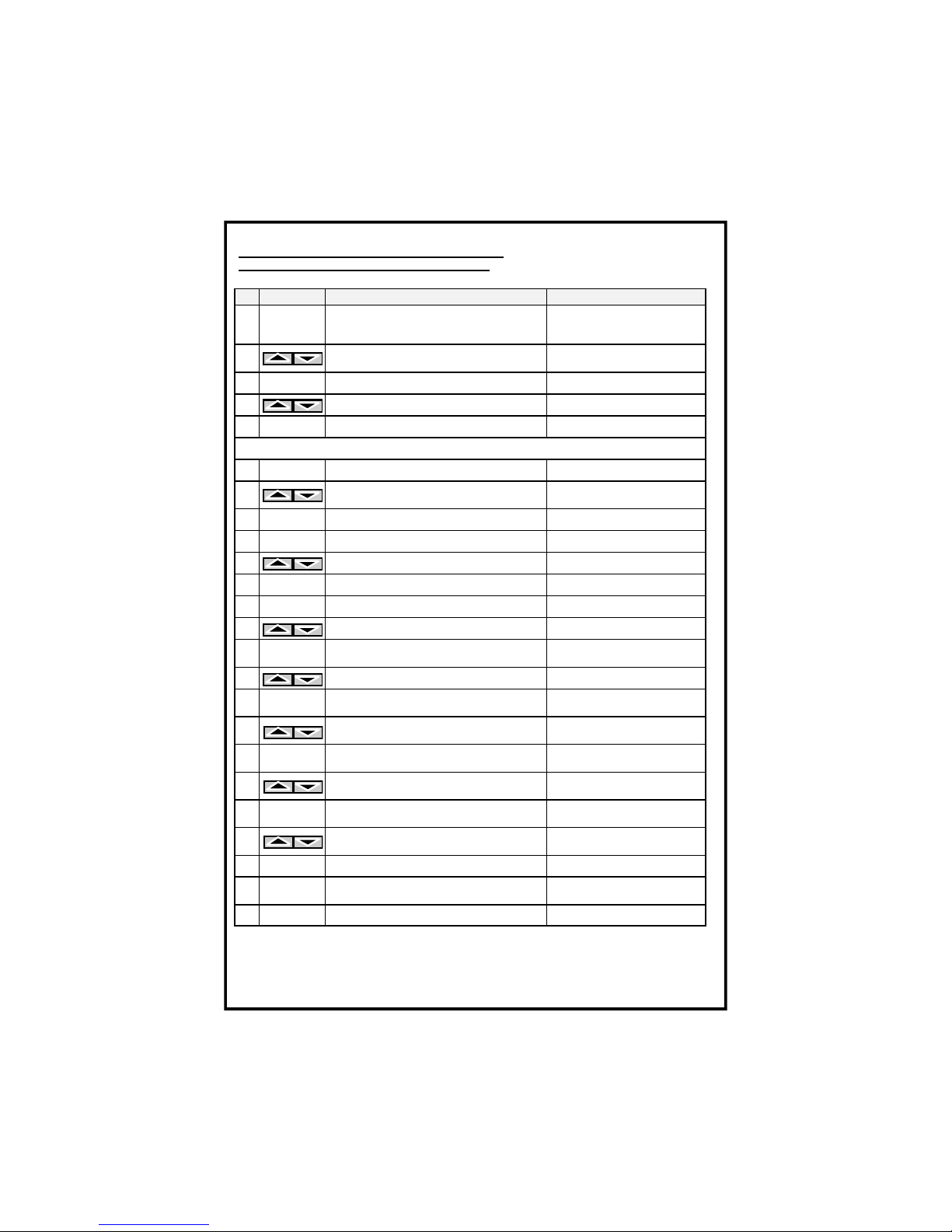
19)编程
注意: PRG-ON LED 指示灯开启:可进行程序修改
PRG-ON LED 指示灯 关闭:程序显示。
项目 功能按键
操作内容
备注
1
PRG/开启
持续按下 PRG 键,当屏幕显示 PRG 字
样显示后,显示 NCH(通道号)字样
如果出现 NOP 的字样,
请参阅“编程锁定”有关
介绍 2
按此上下功能按键,选择通道
有相关的 LED 指示灯指
示所选的通道(1—8)
3
PRG/开启
续按此功能键,将出现 CH1 通道的出
厂高温报警 ALARM 设定门限值
4
利用此功能按键设定所需的门限值
5
PRG/开启
续按此功能键,将出现 CH1 的出厂设
定的跳闸(TRIP)门限值
6
利用此功能按键设定所需的跳闸门限
值
重复项目 3---6 操作,依次对所需的其它通道进行高温报警和跳闸的门限值设定
6
PRG/开启
续按此功能按键,FAN 字样出现,进
行风机设置
7
按此上下功能键进行 YES 或 NO 设
置;如设置 NO 状态直接跳至第 16 项
YES:开启风机控制
NO:不使用风机控制功能
8
PRG/开启
如第 7 项设置 YES,续按此键,屏幕显
示 ON 字样,进行风机启动温度设置
9
PRG/开启
续按此功能键,显示风机启动温度的出
厂设定门限值
10
利用此功能按键设定所需的风机启动
门限温度值
11
PRG/开启
续按此功能键,显示 OFF 字样,进行
风机停止温度门限值设定
12
PRG/开启
续按此功能按键,显示出厂设定的风机
停止门限值
13
利用此上下按键,设定所需风机停止的
温度门限值
14
PRG/开启
续按此功能键,屏显示 HFn 字样
每“n”小时风机自动进
行 5 分钟的自检运行
15
利用此按键设定 n 值
如 n=000,不使用此功能
16
PRG/开启
续按此功能按键,屏幕显示 n.o.或 n.c.
字样,相应报警状态指示闪烁
高温报警输出触点的逻
辑状态
17
利用此上下选择按键,进行设置(n.o.
或 n.c.)
n.o.:常开触点
n.c.:常闭触点

NT538 智能溫控器 第 9/14
✉ Email : didio@tecsystem.asia ; website : www.tecsystem.asia
18
PRG/开启
续按此功能按键,屏幕显示 n.o.或 n.c.
字样,相应报警状态指示闪烁
跳闸报警输出触点的逻
辑状态
19
利用此上下选择按键,进行设置(n.o.
或 n.c.)
n.o.:常开触点
n.c.:常闭触点
20
PRG/开启
续按此功能按键,显示 FCD<>“出厂
设置门槛值”
FCD 是排除误报警功能
(因传感器接触不良或
开路故障所引发的不正
常的温升率(°C/秒)来作
判定)
21
按此上下选择按键用于调整所需门槛
值(参考第 10 页说明)
从“no”至最高为 30°C/
秒(no:禁止该功能)
22
PRG/开启
续按此功能按键,显示 END(结束)
字样
表示编程完成
23
退出
续按此功能按键,存储所加载的数据并
退出编程
如出现 Err 字样:表示编
程错误,同时 LED 显示屏
将跳出问题参数(请参阅
提示 2)
24
PRG/开启
续按此功能按键,返回至步骤 1 重新设
定
1)
可以通过按下
MODE
键返回至前一步。
2)
如果按
ENT
键,出现“
Err
”,这表示发生了如下错误的一种设定:报警(
ALARM
)
温度≥跳闸(
TRIP
)温度,或风机-关闭≥风机-开启温度。请按下
PRG
键返回至
第1步,对设定参数进行修正。
3
)键盘在经过一分钟无任何操作后,仪表将自动退出编程操作,原来被修改的参数不
生效,同时也不会被保存。
NT538 P8 V4-R.1.4 智能温控器
TECSYSTEM SH

NT538 智能溫控器 第 10/14
✉ Email : didio@tecsystem.asia ; website : www.tecsystem.asia
2) 编程操作锁定功能
如果按住 PRG 功能按键进入编程流程(第一步),显示“NOP”字样,这意味着设备内
部的编程选择刀闸开关被打开,造成此编程功能被禁止。要复原编程功能,则必须按照下图
所示开关复位。
不可进行编程操作
可进行变成操作
质保承诺
“NT”系列的温控器都享受从设备的交付日期开始计算有 12 个月的质保期。
质保条款只限于生产工艺,产品功能与精度不符生产厂家所公布的技术规范和产品说明书
所规定的各项内容。
如果温控器被不当操作或供电电源电压超出仪表最大的工作电压范围(20- 270 Vac-dc)而
造成的损坏将不享受此质保承诺
如果因为电源谐波(Harmonic),闪变(Transient)和瞬间峰值(Surge)造成的产品烧坏,
TECSYSTEM 不负责免费保修,如需 TECSYSTEM 工厂进行维修,则所产生的一切费用:
来回运费,工本费用均由客户承担。一旦发生争议,则只能由米兰法院进行裁决。
此质保承诺是按 FREE OUR DOMICILE in CORSICO 原则执行。
22) 对配合 pt100 传感器使用的延长线的技术要求:
电线规格: 20 xAWG 20/19 Cu/Sn
横 截 面: 0.55 mm²
绝缘要求: PVC 105 阻燃材料

NT538 智能溫控器 第 11/14
✉ Email : didio@tecsystem.asia ; website : www.tecsystem.asia
适用标准: CEI 20.35 IEC 332.1
最大工作温度:105°C
电线结构: 三线互绞带屏蔽、有色线、四重结构
需用 Cu(铜)/Sn(锡)线提供屏蔽
外层套封阻燃 PVC 材料
外径为 9.0mm
100 米线束标准包装
TECSYSTEM SH
故障诊断
原因以及纠正措施
即使有电源供应与连接的情况下,仪
表仍然无法启动。
接线端子排没有正确插进到位或接线端子上的电
源线没有拧紧或电源线烧断
措施:先取下检查,并重新安装。
当其中一个通道出现 FOC 或 FCC 故
障时
1、检查 Pt100 传感器的连接。可能传感器接线不
良或损坏。
措施:检查或更换已损坏的传感器。
2、编程通道的数据和实际连接传感器的通道不一
致。需要重新编程
当启动时,显示“ECH”错误信息
由于强干扰导致内存数据损坏或缺陷。
请参阅本规范的第 8 条说明。如果此问题仍然存
在,请与 TECSYSTEM S.r.l.公司技术部门取得联
系。
所有的通道均处于 FCC(短路)传感
器报警状态
传感器端子排接线错误。
请检查线路连接。
一个或多个通道错误温度显示
请与 TECSYSTEM S.r.l.公司技术部门取得联系。
跳闸(TRIP)触点触发,但温度处于
正常水平。
此现象是由传感器损坏或者相应接线不良引起。
通过 T.MAX 功能查看报警故障通道,检查对应的
接线端子或更换对应的传感器。

NT538 智能溫控器 第 12/14
✉ Email : didio@tecsystem.asia ; website : www.tecsystem.asia
23)有关 FCD 功能的说明:
FCD 功能是 NT 系列温控器新增的一种针对 PT100 探测器的动态监控功能
如果温度探头被意外损坏,则突出的问题就是探头自身阻抗快速增加和变化,因此导致温控
器显示的监测温度迅速变化。
显然,这种温升并不是被监控保护的电力设备比如电动机,干式变压器或封闭式变压器等自
身故障引起的。
因此,这时候必须要监定为传感器处于故障状态以避免输出(ALARM)高温报警信号甚至
是跳闸(TRIP)等误报警事故。
当温控器是应用于对电机马达的监控时,快速温升 FCD 报警的定义不能单指传感器故障,
也可能是转子发生被卡住或者空转的故障状态,因此用户应进行按不同的应用情况为 FCD
报警作不同的定义与应用。
当温升速率超过设定的速率(n°C/秒)(n 值:从 1 到 30),通过激活 FCD 功能,温控器
可以通过输出触点 7-8-9 输出 FAULT 错误报警信号。
通过参数设定,用户可以根据不同的使用要求选择如下不同的精度等级:
- 从 1 至 10:高灵敏度,用于即时探测电动机转子失速情况。
- 从 10 至 20:平均灵敏度,用于监测影响传感器采集数据,线路连接不良以及传感器缺
陷等各种干扰信息。
- 从 20 至 30:低灵敏度,用于的场合是,高灵敏度设置可能会导致不必要的 FCD 功能中
的错误报警
- 设置“no”模式,则 FCD 功能被禁止。
当一个通道出现 FCD/FAULT 故障报警时,相关的高温报警(ALARM)和跳闸(TRIP)报
警功能将被锁住,只是显示温度快速升高的 FCD 报警,避免产生错误的高温报警(ALARM)
和跳闸(TRIP)报警。按下 Reset 键删除所有通道的 FCD 信号,检测修复仪表故障。

NT538 智能溫控器 第 13/14
✉ Email : didio@tecsystem.asia ; website : www.tecsystem.asia
10 NT538 P8 V4-R1.4 智能温控器 TECSYSTEM SH
NT 538
线路连接
Pt100 输入
报警输出触点
高温报警输出
跳闸输出
FULT 故障报警输出
风机控制输出
电源供应 24-240 VAC-VDC
扩展模块输出
NT538 扩展模块
NT538 P8 V4-R1.4 智能温控器 11
白色
红色
红色
如果 TX 接
点在模块内
有提供

NT538 智能溫控器 第 14/14
✉ Email : didio@tecsystem.asia ; website : www.tecsystem.asia
TECSYSTEM SH
NT 538 测试公告
此设备已经按照以下流程初步通过测试:
N°
内容 说明
1
安装板检测
2
输入工作状态检测
3
继电器触点和输出检测
4
按钮工作状态检测
5
指示灯检测
6
在 0 和 200°C 状态下进行校准
7
软件工作状态检测
8
老化至少 24 小时
日期:
质量控制
TECSYSTEM SRL
(签字)
NT538 P8 V4-R1.4 智能温控器
 Loading...