

TECSYSTEM S.r.l.
20094 Corsico (MI)
Tel.: +39-024581861
Fax: +39-0248600783
NT210 K
TPL503
INSTRUCTION MANUAL
ENGLISH
1MN0079 REV. 0
operates with ISO9001:2008 certified quality system
“Translations of the original instructions”
http: //www.tecsystem.it
R. 1.5 31/01/18

2
NT210 K
PAGE
1) SAFETY REQUIREMENTS
…………………………………..
4
2) ACCESSORIES
…………………………………..
5
3) TECHNICAL SPECIFICATIONS
…………………………………..
6
4) TPL503 SENSOR INSTALLATION PROCEDURE
…………………………………..
8
5) FRONT PANEL
…………………………………..
10
DISPLAY
…………………………………..
11
CHECKING THE WORK PROGRAM
…………………………………..
—
LED TEST
…………………………………..
—
ALARM RELAY TEST
…………………………………..
—
ALARM RELAY SILENCING (AL1)
…………………………………..
—
5) INSTALLATION
…………………………………..
12
6) ELECTRICAL CONNECTIONS
…………………………………..
13
NT210
…………………………………..
—
POWER SUPPLY
…………………………………..
14
ALARMS AND VENTILATION
…………………………………..
—
COOLING FAN CONTROL
…………………………………..
15
FAN TEST
…………………………………..
TPL503 CONNECTIONS
…………………………………..
—
PROGRAMMED DATA DIAGNOSTICS
…………………………………..
—
TEMPERATURE MEASUREMENT (T)
…………………………………..
—
PRESSURE MEASUREMENT (P)
…………………………………..
16
PRESSURE SENSOR ZEROING
…………………………………..
—
LEVEL MEASUREMENT (L)
…………………………………..
—
7) PROGRAMMING
…………………………………..
17
NOTES ON THE FCD FUNCTION
…………………………………..
19
NOTES ON THE FPS FUNCTION
…………………………………..
—
INTRODUCTION
First of all we wish to thank you for choosing to use a TECSYSTEM product and recommend you read this instruction
manual carefully: You will understand the use of the equipment and therefore be able to take advantage of all its
functions.
ATTENTION! THIS MANUAL IS VALID AND COMPLETE FOR THE NT210 K VERSION COMBINED WITH THE
TRANSPARENT TPL503 SENSOR.

3
NT210 K
PAGE
8) RS485 MODBUS OPTION
…………………………………..
20
INTRODUCTION TO THE MODBUS INSIDE
…………………………………..
—
OPERATING NOTES
…………………………………..
—
DATA TRANSMISSION ON MODBUS NETWORK
…………………………………..
—
RS485 ELECTRICAL CONNECTIONS
…………………………………..
—
DATA FRAME
…………………………………..
—
DATA PACKET
…………………………………..
—
FUNCTION CODE
…………………………………..
21
CODE 3(10).
…………………………………..
—
CODE 16(10).
…………………………………..
—
NOTES FOR REMOTE PROGRAMMING
…………………………………..
—
ERROR CODES (exception code)
…………………………………..
—
POLLING FREQUENCY
…………………………………..
—
MODBUS MAPPING TABLE
…………………………………..
22
CRC CALCULATION
…………………………………..
29
PARAMETER DESCRIPTION
…………………………………..
—
ALGORITHM
…………………………………..
—
12) WARRANTY REGULATIONS
…………………………………..
—
13) TROUBLESHOOTING
…………………………………..
30
14) EQUIPMENT DISPOSAL
…………………………………..
—
15) USEFUL CONTACTS
…………………………………..
—
4
NT210 K
SAFETY REQUIREMENTS
Read the manual carefully before starting to use the control unit. Keep the instructions for future reference.
Do not open the device, touching any internal components can cause electric shock. Contact with voltage over
50 Volts can be fatal. To reduce the risk of electric shock, do not dismantle the back of the device for any reason.
Moreover its opening would void the warranty.
Before connecting the device to the power supply, make sure that all the connections are correct. Always
disconnect the unit from the supply before any cabling modification.
Any intervention on the equipment must be entrusted to a qualified repair engineer
Failure to comply with these instructions can cause damages, fires or electric shock, and possible serious
injuries!
POWER SUPPLY
The NT210 K series has UNIVERSAL power supply, i.e. it can be supplied by 24 to 240 Vac-Vdc, irrespectively of polarity
in Vdc.
Before using it, make sure the power cable is not damaged, kinked or pinched. Do not tamper with the power cable.
Never disconnect the unit by pulling the cable, avoid touching the pins. Do not carry out any connecting/disconnecting
with wet hands. To disconnect the device, do not use objects such as levers. Immediately disconnect the device if you
smell burning or see any smoke: contact technical service.
LIQUIDS
Do not expose the equipment to splashes or drops, do not position it in places with humidity exceeding 90% and never
touch with wet or humid hands during storms. If any liquid penetrates the control unit, disconnect it immediately and
contact technical service.
CLEANING
Disconnect the power cable before cleaning the control unit, use a dry cloth to dust it, without any solvent or detergents,
and compressed air.
OBJECTS
Never insert any objects into the cracks of the control unit. If this happens, disconnect the control unit and
contact an engineer.
USE RESERVED TO QUALIFIED PERSONNEL
The purchased goods are a sophisticated electronic device that is totally unsuitable to be used by non-qualified
personnel. Any intervention must be carried out by a specialist engineer.
ACCESSORIES
The use of non-original accessories or spare parts might damage the unit and endanger users' safety. In the event of
faults, contact technical service.
LOCATION
Install the control unit indoors, in a place protected from water splashes and sun rays. Do not place near heat sources
exceeding the parameters stated in this manual. Position on a stable surface, far from any possible vibrations. Position
the unit as far as possible from any intense magnetic fields.
REPAIRS
Do not open the control unit. For any fault, always use qualified personnel. The opening of the control unit and/or the
removal of the series identifying label entails the automatic forfeiture of the warranty. The Warranty seal is applied to all
devices, any attempt to open the unit would break the seal and cause the consequent automatic forfeiture of the warranty.
TECHNICAL INFORMATION
Mail: ufficiotecnico@tecsystem.it — tel: 02/4581861
ATTENTION:
5
NT210 K
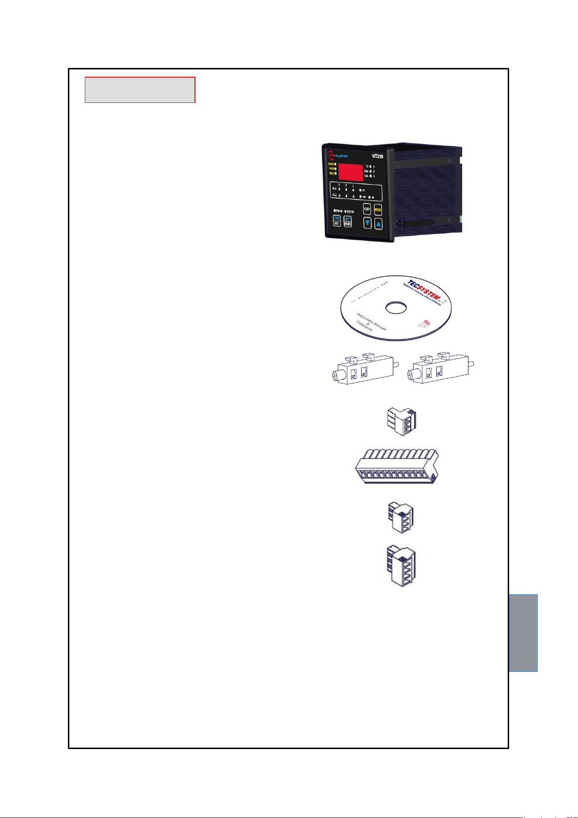
ACCESSORIES
The following objects are present inside the box:
Control unit
Instruction manual CD
2 blocks for panel mounting
1 supply terminal 3 poles pitch 5
Code: 2PL0367- Screws tightening torque 0.5Nm
1 relay terminal 11 poles pitch 5
Code: 2PL0359 - Screws tightening torque 0.5Nm
1 RS485 terminal 3 poles pitch 3.81
Code: 2PL0366 - Screws tightening torque 0.25Nm
1 TPL503 sensor Tecsybus terminal 4 poles pitch 3.81
Code: 2PL0368 - Screws tightening torque 0.25Nm
1MN0030 REV. 1
ATTENTION: always install the device using the terminals included in the pack. The use of terminals
other than those included with the control unit might cause malfunctions.

6
NT210 K
TECHNICAL SPECIFICATIONS
NT210 K
POWER SUPPLY
Supply rated values
24-240 Vac-Vdc (50/60Hz)
Supply min/max values
20-270 Vac-Vdc (50/60Hz)
Vdc with reversible polarities
●
INPUTS
Digital input for the connection with the TPL503 sensor
●
OUTPUTS
2 alarm relays (ALARM AND TRIP) SPDT
●
1 fault sensor or operating failure (FAULT) relay SPDT
●
Output relay with 5A-250Vca-res COSФ=1 contacts.
●
Ventilation management relay SPST
FAN
Power-link output (9Vdc 100 mA max.) to feed the TPL503 sensor.
●
COMMUNICATION
RS485 Modbus RTU serial output
●
DIMENSIONS
100x100 mm– din43700-depth 131mm (terminal block included)
Hole 92 x 92 mm
TEST AND PERFORMANCE
Construction in compliance with CE regulations
●
Protection from electrical interference EN 61000-4-4
●
Dielectric strength 1500 Vac for 1 minute between relays and supply, relays and power-link,
relays and RS485 input, power-link and supply, RS485 input and supply.
●
Ambient operating temperature from –20°C to +60°C
●
Humidity 90% non-condensing
●
Housing NORYL 94 _V0
●
Absorption 5VA
●
Data storage: 10 years minimum
●
IP65 polycarbonate front film
●
Electronic protection only on customer's request
Option
DISPLAY AND DATA MANAGEMENT
1 x 13 mm display with 3 digits to display T-P-L values and messages
●
3 LEDs to show the displayed oil temperature (°C), pressure (mbar) and level.
●
6 LEDs to show the T-P-L alarm status
●

7
NT210 K
TECHNICAL SPECIFICATIONS
NT210 K
1 LED to show the correct connection of RS485 with TPL503
●
Temperature control: from 0°C to + 120°C
●
Oil pressure reading: from -400 to 500 mbar (DEP indication for negative value)
●
Oil pressure controls: from 0 mbar to 500 mbar
●
Level control in 3 modes (FULL - ALARM - TRIP ).
●
2 alarm thresholds (AL.1/AL.2) for temperature, pressure and level.
●
1 threshold for the quick increase of the programmable pressure (FPS)
●
1 threshold for the quick increase of the programmable pressure (FCD)
●
2 thresholds for ventilation ON-OFF control, controlled by the oil temperature
●
Incorrect programming warning
●
Selection of the data display mode between automatic and manual scan and memory.
●
Maximum temperature and pressure memory recorded since the last reset
●
Front alarm reset button
●
Sensor fault diagnostics (FLT)
●
TPL503 TECHNICAL SPECIFICATIONS
TPL503
POWER SUPPLY
Direct connection to the Power-link source of the NT210 K control unit.
9VDC 100mA max
MEASURED QUANTITIES
Oil temperature: from –20 to +120°C
●
Resolution: ±1°C
●
Accuracy: ±1% full scale value
●
Oil pressure: from -400 to 500 mbar
●
Resolution: ±10 mBar
●
Accuracy: ±2% full scale value
●
Level in 3 modes (FULL - ALARM - TRIP ).
●
TEST AND PERFORMANCE
T.P.L. parameter management in compliance with the IEC EN 50216-3/A standard
●
Protection from electro-magnetic interference IEC EN 61000-4-4
●
Dielectric strength 2500 Vac for 1 minute
●
Operating temperature of the electronic part: -20°C to + 85°C
●
Self-diagnosis circuit of the T-P-L sensors.
●
Maximum cable length: 40 m (4 wires AWG22/24, shielded, impedance 120 ohm)
●
Pressure sensor resistant to the corrosion of mineral oil.
●
8
NT210 K
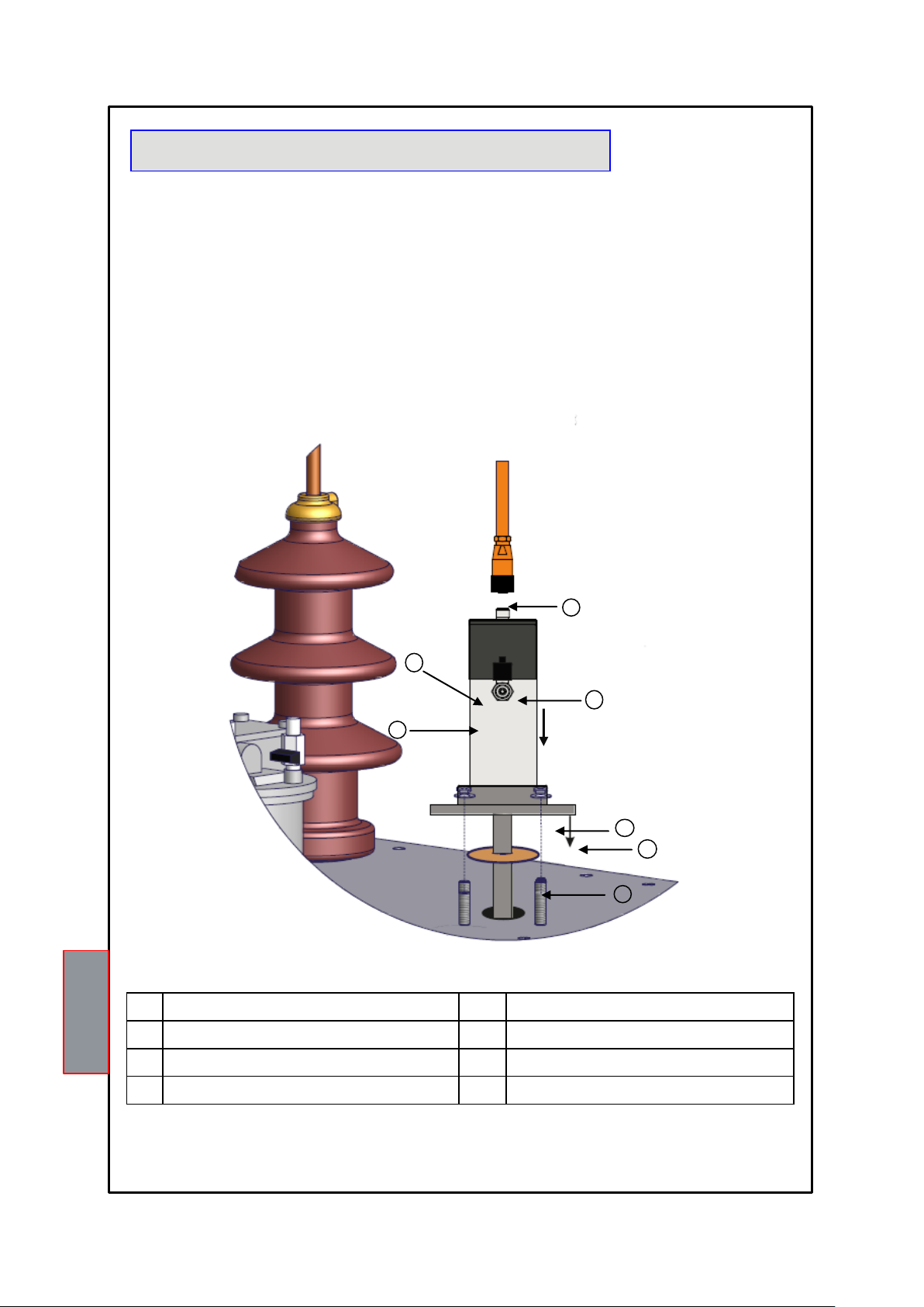
1)
Cork- rubber gasket
5)
Air release tap
2)
TPL503 sensor base
6)
Air release tap plug
3)
Flange fixing bolts and washers
7)
TPL503 data and supply cable
4)
TPL503 sensor and closing gasket OR
1MN0073 REV. 2
2
3
6
4
7
NOTE: The sensor stem is inserted 10cm inside of the transformer, the TPL503 must not interfere with other internal
elements; In addition w e suggest always to respect the safety distance between the sensor and the live parts of the
monitored machine .
INTRODUCTION
The TPL503 sensor is fitted on the transformer cover in oil sealed box with integral filling.
The installation method is described below just for information purposes; the installer is fully responsible for the
installation.
INSTALLATION PRECAUTIONS
The transformer must be disconnected.
The transformer dielectric fluid must be at ambient temperature (about 20°C).
The level of dielectric fluid must be slightly below the transformer cover.
The TPL503 hole on the transformer must be open .
The installing area of the sensor must be free from welding or painting residue and perfectly clean.
The cork- rubber gasket, TPL base, must adhere fully to the support surface (note: replace the gasket every time it is
removed to the TPL base)
NECESSARY TOOLS
A 13x13mm spanner
A 5mm Allen wrench (inbus)
9
NT210 K
STEP BY STEP DESCRIPTION pictures on page 8.
NOTE: Bolts and washers for securing the sensor are not supplied by Tecsystem.
1) Following the suitably sized hole centering on the transformer fixing pins: insert the cork rubber (1) and mounting the
TPL503 base (2) into the appropriate hole in the transformer cover.
2) Insert the 4 washers (3) in the fixing pins.
3) Insert the bolts (3) onto the fixing pins and screw them in, use the 13x13 spanner, tighten but without straining
(strength recommended 8 Nm).
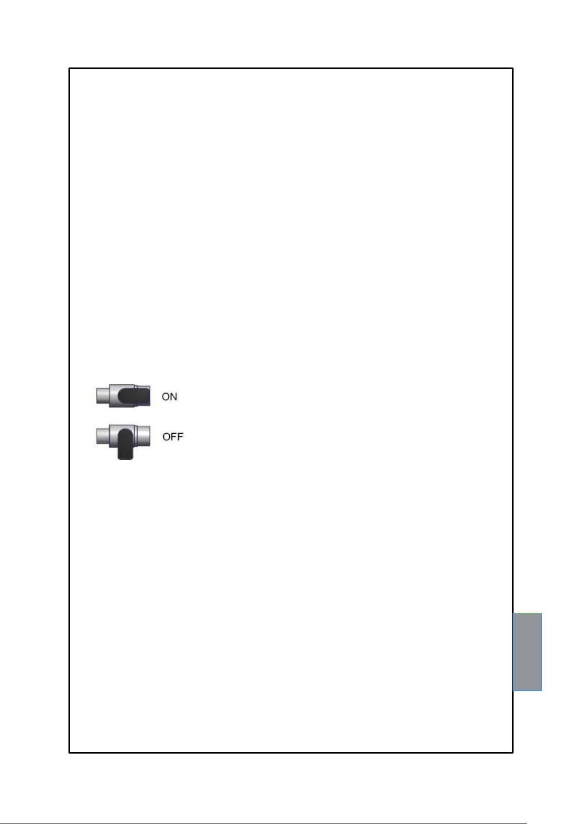
4) Check that the air release tap (5) is OFF.
5) Filling/Finish to fill the transformer.
6) Insert OR ring on the TPL503 base and tightening the TPL503 sensor (4) immediately over the base to its end.
7) Remove the plug on the air release tap (6), use the 5mm Allen wrench (tighten but without straining).
8) Remove the protection cap on the data / supply connector.
9) Connect the data / supply cable (7), tighten the connector manually (TPL503 connection on page 15).
10) Open the release tap (6), position ON, until the oil shows no air bubbles (sensor air bleeding), turn the tap to the OFF
position. Repeat the operation until all the air is released.
Attention: bleeding must be carried out taking into consideration the transformer operating conditions, with the
transformer switched off and a temperature of about 20°C (or ambient); the installer or maintenance engineer takes full
responsibility for this operation.
11) Insert the tap plug (6) and screw fully in, using the 5mm Allen wrench.
12) Zero the pressure sensor, see page 16.
13) With the transformer switched off, checking the values displayed by the control unit:
Temperature (ambient) - Pressure (000) - Level (full)
14) Mark the closing TPL503 sensor (4) with a label.
NOTES ON THE ASSEMBLY
The installation of the sensor must be carried out by a specialized engineer following the above procedure carefully.
For a correctly working of the system, the oil level must be in line with the release tap (6).
The end of the stem (temperature measurement) is placed 10cm below the transformer cover.
Before starting the transformer, always check the bolts are tightened and bleed the air.
The bolts loosening or the presence of air in the system might cause malfunctioning.
The presence of air bubbles might affect the level reading, therefore it is necessary to check there is no air in the system.
Filling or topping up the oil must be done with the transformer switched off and cold (ambient temperature about 20°C).
10
NT210 K
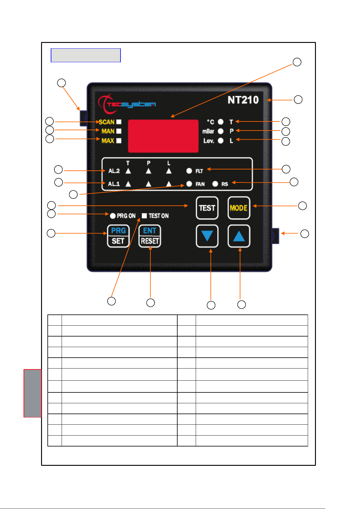
FRONT PANEL
1)
3-digit display
13)
Relay ON test (yellow) LED
2)
Control unit series
14)
Programming button
3)
Temperature display (green) LED
15)
PRG ON (yellow) LED
4)
Pressure display (green) LED
16)
LED/relay test button
5)
Level display (green) LED
17)
FAN warning (green) LED
6)
FAULT warning (red) LED
18)
T-P-L alarm activation AL1 (red) LED
7)
RS communication (TPL503) (green) LED
19)
T-P-L alarm activation AL2 (red) LED
8)
Scanning mode selection button
20)
T-max mode selection (red) LED
9)
Fixing block
21)
Man mode selection (yellow) LED
10)
UP button
22)
Scan mode selection (yellow) LED
11)
DOWN button
23)
Fixing block
12)
Enter/Reset button
1 2 3 4 5
6 7 8 9 10
11
12
13
15
14
16
17
18
19
20
21
1MN0079 REV. 0
22
23

11
NT210 K
If one of the LEDS does not work, please return the control unit to TECSYSTEM for repair.
DISPLAY
Pressing the MODE button, the display viewing modes are set:
SCAN: the unit displays the T-P-L values scanned (every 2 seconds)
MAN: manual reading of the T-P-L values using the up/down buttons
T.MAX: the unit displays the maximum temperature and pressure values reached, the minimum level recorded
and the possible alarms or faults that have occurred after the last reset.
Select the channels with , zero the values with RESET.
CHECKING THE WORK PROGRAM
To check the set protection levels, press the PRG button briefly.
Vis appears for 2 seconds, confirming you have entered viewing mode.
By pressing the PRG button repeatedly, all the previously set values are scrolled through in sequence.
After 1 minute's keyboard inactivity, the programming viewing procedure is automatically abandoned.
To end viewing, press the ENT button.
LED TEST
We recommend the unit LEDs are tested regularly.
For this operation press the TEST button briefly, all the displays light up for 2 seconds.
ALARM RELAY TEST
This function allows carrying out a test of the relay operation without having to use supplementary equipment.
To start the test procedure, keep the TEST button pressed for about 5 seconds: TST is displayed for 2 seconds, confirming
you have entered the Relay Test mode.
The flashing LED shows the relay to be tested, select the desired LED with the sliders.
Press the SET and RESET buttons to energise and de-energise the relay to be tested, ON-OFF appears on
the display. After 1 minute's keyboard inactivity, the RELAY TEST procedure is automatically abandoned. To
end the RELAY TEST procedure, press the TEST button.
AL1 ALARM RELAY SILENCING
If you wish to silence the ALARM, press the RESET button: the relay is de-energised and the AL1 LED, that was ON,
starts flashing.
Silencing is automatically disabled when the temperature goes below the alarm threshold.
12
NT210 K
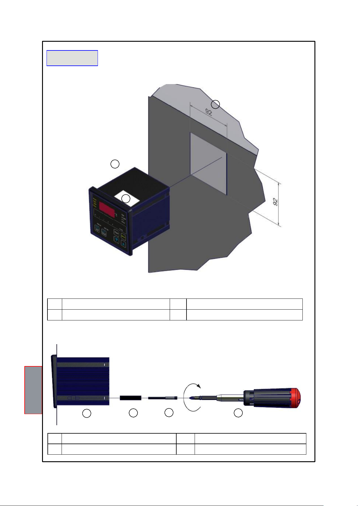
1
1)
Control unit
2)
Panel hole dimensions (+0.8mm tolerance)
3)
Identification label
1)
Control unit
3)
Fixing screw
2)
Fixing block
4)
Crosshead screwdriver #1X100mm
MOUNTING
Drill a 92 x 92 mm hole in the panel sheet.
2
1
3
1MN0007 REV. 0
Fix the unit securely with the blocks supplied.
1 2
3
4
1MN0008 REV. 0

13
NT210 K
1)
Power supply (24-240 Vac-dc 50/60Hz)
3)
RS485 Output
2)
Relays (ALARM-TRIP-FAULT-FAN)
4)
TPL503 sensor connection
ELECTRICAL CONNECTIONS
1 2 3 4 1MN0053 REV. 0
RELAY CONNECTION EXAMPLE
SENSOR CONNECTION
Output relay with 5A-250Vac-res COSФ=1 contacts
LIGHT
SIGNAL
SYSTEM
STOP
AUDIO
SIGNAL
NT210 K
NOTE: Carry out the electrical connections on the removable terminal blocks only after disconnecting them from the unit.
Connector
Connector connection colours:
1.
+ RS white
2.
+ PWL brown
3.
- PWL black
4.
- RS Blue
Note: with the power to the unit ON, the FAULT relay switches, contacts 8-9 open (NO) and 7-9 closed (NC), read paragraph
ALARMS AND VENTILATION page 14
FAULT 8-9 NC: ALARM FAULT OR POWER OFF FAULT 7-9: NC POWER ON
7 8 9
7 8 9

14
NT210 K
To protect the control unit from line overvoltages, we recommend using the electronic PT-73-220 surge limiter,
designed by TECSYSTEM S.r.l. specifically for this purpose.
Alternatively we recommend 24 Vac or, even better, 24 Vdc supply voltages are adopted.
IMPORTANT WARNING
Before carrying out the insulation test of the electrical panel the control unit is installed on, disconnect it from the power supply
to prevent it from being seriously damaged.
POWER SUPPLY
The NT210 K control unit has UNIVERSAL power supply, i.e. it can be supplied by 24 to 240 Vac-Vdc, (50/60 Hz)
irrespectively of polarity in Vdc (terminals 40-42).
This is obtained thanks to the use of a tested power supply unit, newly designed and manufactured, that frees installers from
worrying about the correct Vac and Vdc supply.
Earth must always be connected to terminal 41.
When the unit is supplied directly by the secondary of the transformer to be protected, it can be burnt out by strong
overvoltages.
This happens if the main switch is closed and the transformer has no load (blank test). The above is much more
obvious when the voltage of 220 Vac is taken directly from the bars of the transformer secondary and there is a fixed
bank of capacitors to correct the power factor of the transformer itself.
If an existing control unit must be replaced with a new one, to guarantee its correct and safe operation, the
sensor/relay/supply connecting terminals must be replaced with the new terminals supplied.
ALARMS AND VENTILATION
When the control unit is in one of the modes mentioned below, it does not monitor the temperature and the relays are all
blocked.
Vis. programming display
PRG Programming.
Relay test.
The ALARM and TRIP relays switch only when the set temperature, pressure and level thresholds are exceeded.
The FAULT relay switches when the unit is powered, contacts 7-9 closed (NC) and 8-9 open (NO), and holds till one
of the following events takes place:
Data storage fault (Ech message).
TPL503 sensor fault:
1. ER0 -> communication error between TPL503 and NT210 K
2. ER1 -> faulty TPL503 internal temperature sensor
3. ER2 -> TPL503 electronic card temperature > than 85°C
4. ER3 -> TPL503 electronic card temperature < than -20°C
5. FLT T -> faulty oil temperature sensor
6. FLT P -> faulty pressure sensor
7. FCD -> quick increase in oil temperature (exceeding x °C/sec)
8. FPS -> quick increase in oil pressure (exceeding x mbar/sec)
Insufficient supply voltage.
During the power on reset after programming (PRG) of the control unit (local or via Modbus).
NOTE: do not connect the FAULT relay to the transformer tripping circuit to avoid unwanted system interruptions.
The FAN contact can be used to control the cooling fans or it can be inserted into the air conditioning system of the
room where the transformer is located.
NOTE: always disconnect the unit before performing any electrical connections.

15
NT210 K
COOLING FAN CONTROL
The NT210 K unit can control the cooling system of the oil temperature of the operating machine (i.e. ON at 80°C - OFF
at 70°C).
FAN TEST
By programming (HFn), it is possible to have the fans operating 5 minutes every "xxx" hours, regardless of the column
or ambient temperature values (i.e.: with HFn=001 the fans are activated for 5 minutes every hour).
This function aims at verifying the operation of the fans and their control apparatus periodically in periods when they
would not be used for a long time.
Setting 000 as a value inhibits the function.
TPL503 CONNECTIONS
The TPL503210 is fitted with an M12 IEC 947-5-2 connector that must be connected to the control unit with the cable
supplied, electrical connections are shown on page 13.
The signals present are power (POWER LINK) and data output (RS485). Note: All the
cables transferring signals must:
be separated from the power cables
be shielded cables with twisted conductors
have at least 0.5 mm² section
be twisted if there is no shield
be firmly fixed inside the terminal boxes
PROGRAMMED DATA DIAGNOSTICS
In case of failure of the internal memory or alteration of the programmed data, at start-up Ech is displayed
with the relative warning of the Fault contact.
In this case, for safety reasons, the default parameters are loaded automatically (see the programming table on pages
17 and 18 according to the model purchased).
Eliminate the Ech message by pressing RESET and enter the desired values.
Finally switch the unit off and back on to check the memory works correctly, if it is damaged Ech will be displayed again
(send the control unit to TECSYSTEM srl for repair).
TEMPERATURE MEASUREMENT (T)
The reading of the temperature takes place using an RTD Pt100 sensor placed at the end of the stem.
When the temperature exceeds the set pre-alarm threshold by 1°C (AL.1) the ALARM relay switches and the ALARM
LED comes ON while T. is displayed.
When the temperature exceeds the set alarm threshold by 1°C (AL.2) the TRIP relay switches and the TRIP LED comes
ON while T. is displayed.
As soon as the temperature goes back to values equal to or lower than the threshold set for the
ALARM and TRIP relays to switch, these relays deenergise and the relative LEDs switch off.
If the FCD function is activated and the set temperature increase speed is exceeded, the FAULT relay switches and
FCD is displayed on the screen.
With FCD the ALARM and TRIP functions are inhibited. Press
RESET to cancel FCD.

16
NT210 K
Level value
Display
Gas formation / loss
FULL (3)
0 cm³/90 cm³
ALARM /AL1 (2)
100 cm³/180 cm³
TRIP /AL2 (1)
190 cm³ and more
PRESSURE MEASUREMENT (P)
The pressure reading is made by a sensor placed under the head, through the specially provided opening.
The reading range of the sensor is -400 to + 500 mbar, the display negative values is made by indication DEP
and the relative value of depressure.
Setting for ALARM and TRIP contains just the positive value 0 to + 500 mbar.
When the pressure exceeds the set pre-alarm threshold (AL.1) by 10mbar the ALARM relay (AL1) switches, the
ALARM LED (AL1) comes on and P. is displayed. When the temperature exceeds the set pre-alarm threshold (AL2)
by 10 mbar, the TRIP(AL2) relay switches, the TRIP LED comes on and P. is displayed.
As soon as the pressure goes back to values equal to or lower than the threshold set for the ALARM and
TRIP relays to switch, these relays deenergise and the relative LEDs switch off.
If the FPS function is activated and the set pressure increase speed is exceeded, the FAULT relay switches and
FPS is displayed on the screen. In this case the ALARM and TRIP functions are always active.
PRESSURE SENSOR ZEROING
To benefit from the precision offered by the electronic pressure sensor, we recommend the scale value is zeroed
before starting the transformer that must be cold and stable at ambient temperature (±20°C):
1) Press the MODE button and go to MAX mode
2) Press MODE again without releasing it for 6 seconds until the control unit is reset.
This operation will allow compensating for any reading tolerances due to differences in altitude or transformer filling
pressure.
For the system to be operating correctly the transformer must be cold.
LEVEL MEASUREMENT (L)
The level sensor measures quantity of oil into the sensor TPL503 case; the reading is expressed in three different
modes:
When the level reaches 0 (L2 threshold activated), alarm AL2 is triggered due to the minimum level being exceeded
and the TRIP relay switches.
By enabling the Alarm function or AL1 (YES), see programming on page 17, the alarm relay is triggered when the
level reaches the loss value of 100 cm³, with NO the function is disabled.
By enabling the Trip function or AL2 (YES), see programming on page 17, the trip relay is triggered when the level
reaches the loss value of 190 cm³, with NO the function is disabled.
The TPL503 must be installed so that the base end position corresponds to the minimum level below the
transformer cover, below which the warning must be triggered and the transformer tripped.
IMPORTANT WARNING
The stated oil volume/level values refer to the use of mineral oils with the following density: 888 Kg/m³ at the
temperature of 15°C (mineral oil general specifications).
The presence of air bubbles inside the transformer is identified as formation of gas which can cause a decrease in the
level indication and the activation of the Alarm and Trip signals.
17
NT210 K
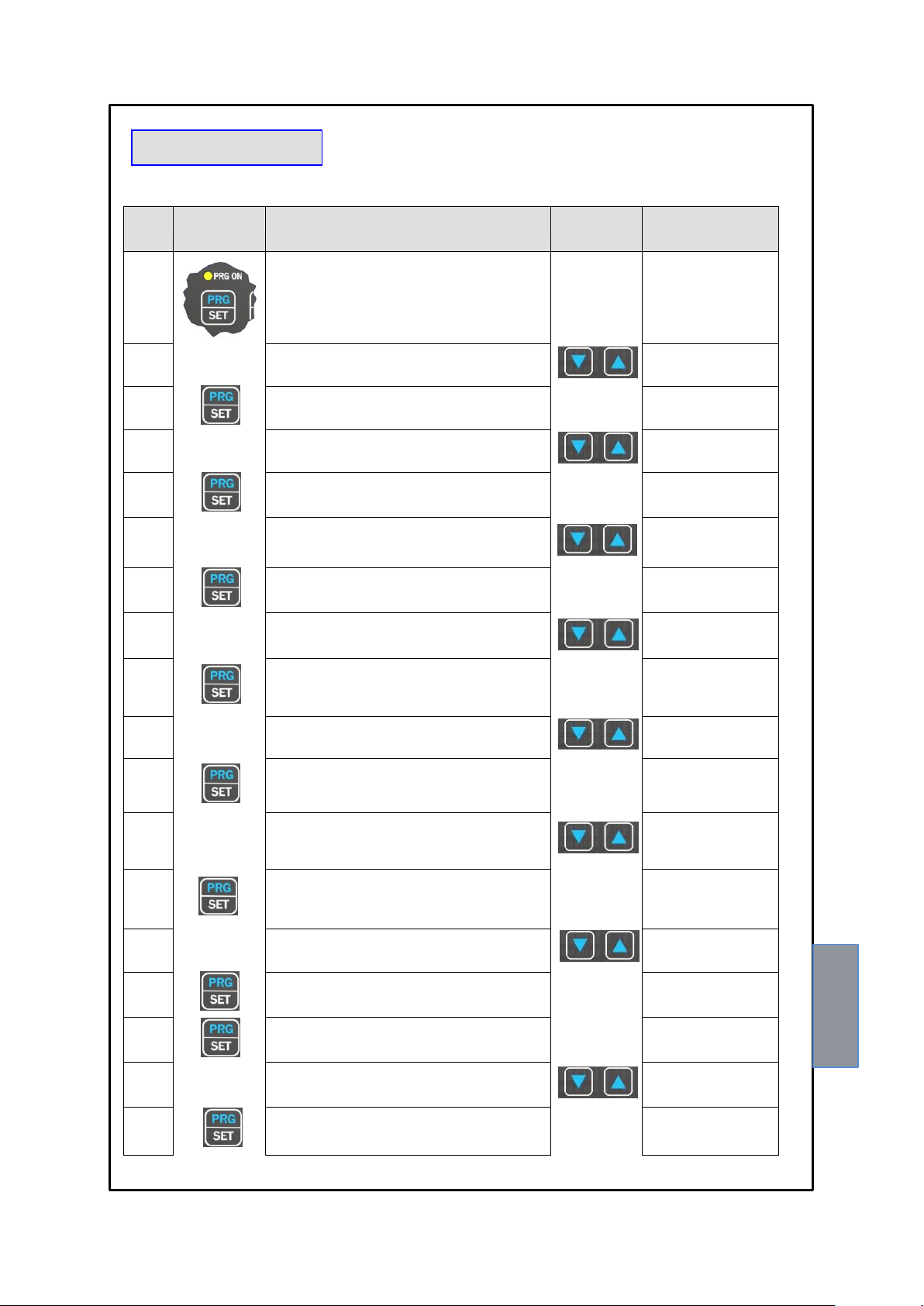
STEP PRESS
EFFECT
PRESS NOTES
1
Keep the PRG button pressed till the PRG-ON LED lights
up. After PRG the temperature ALARM (AL1) threshold is
displayed
2
Set the desired threshold
Default 80°C
3
The temperature TRIP (AL2) threshold is displayed.
4
Set the desired threshold
Default 90°C
5
The pressure ALARM (AL1) threshold is displayed
6
Set the desired threshold
Default 100mbar
7
The pressure TRIP (AL2) threshold is displayed.
8
Set the desired threshold
Default 200mbar
9
The level/gas ALARM (AL1) threshold is displayed
10
Select YES or NO
Default NO
11
The level/gas ALARM (AL2) threshold is displayed
12
Select YES or NO
Default YES
13
The Fan LED flashes and Yes/No is displayed
14
Select YES or NO
Default YES
15
ON is displayed
16
The ON threshold of the FANS is displayed
Default 70°C
17
Set the desired threshold
18
OFF is displayed
PROGRAMMING
NT210 K

18
NT210 K
19
The OFF threshold of the FANS is displayed
Default 60°C
20
Set the desired threshold
21
HFN is displayed
Cyclical test of the fans for 5
minutes every "n" hours
22
Display 000
Default 000= function disabled
23
Set the desired number of hours
Default 000
24
FCD <> "datum" is displayed
Fault due to quick temperature
increase (°C/sec) Default NO
25
Set the desired value (see page 19)
Default no "function excluded"
26
FPS <> "datum" is displayed
Fault due to quick pressure
increase (mbar/sec) Default NO
27
Set the desired value (see page 19)
Default no "function excluded"
28
ADR <> "datum" is displayed
Modbus address Default 001
29
Set the desired address
From 1 to 255
30
BDR <> "datum" is displayed
Modbus transmission speed
Default 9.6 Kb/s
31
Set the desired speed
From 2.4 Kb/s to 38.4 Kb/s
32
PAR <> "datum" is displayed
Parity bit selection
Default NO
33
Set the desired speed
None (No), Even (EVE), Odd
(ODD)
34
END is displayed
End of programming
35
Storing the settings and exiting programming
Err: incorrect programming of
the LED values (note 2)
36
Return to step 1
1)
It is possible to go back to the previous step by pressing the MODE button.
2)
If, when pressing ENT, "Err" is displayed, it means that one of the following errors have been made:
ALARM ≥ TRIP or FAN-OFF ≥ FAN-ON. Press PRG to go back to step 1 and correct the data.
3)
After 1 minute's keyboard inactivity programming is abandoned without saving the data.
4)
At the end of programming the FAULT relay is disabled till the control unit is restarted.
5)
During programming the control unit does not control/protect the monitored machine.

19
NT210 K
ATTENTION:
We recommend you check the control unit before starting the device.
The default parameters set by TECSYSTEM might not suit your requirements.
Programming the device is the end user’s responsibility: the set alarm thresholds and the
enabled functions described in this manual must be checked (by a specialized technician)
referring them to the application and system characteristics on which the control unit is
installed.
NOTES ON THE FCD FUNCTION
The NT series equipment boasts an innovative control function combined with the dynamic status of the Pt100 sensor
inside the TPL503.
Activating FCD, the control unit analyses the increase in temperature ∆T (*) recorded in a second (°C/sec).
Enabling the function, the user can select the value (∆T) from a minimum of 1°C/sec (2°F) to a maximum of 30°C/ sec.
(54°F). If the value sensed is higher than the value set by the user, the control unit inhibits the possible activation of the
ALARM and TRIP alarms and switches the FAULT relay (7-8-9), displaying the message "Fcd fault".
Example: if we set the function to 5°C, FAULT for FCD will switch only if the control unit senses an increase in ∆T of
over 5°C in a second on the monitored system.
Setting "no" disables the FCD function.
When a channel is in FAULT for FCD, the Alarm and Trip warnings are inhibited; therefore only the quick temperature
increase is highlighted.
Press Reset to delete the FCD warnings on all channels and reset the FAULT relay.
Possible FCD applications
Identification of a possible induced disturbance on the sensor line
If the installation instructions are not complied with (see TPL503 connections on page 15), any disturbance on the Pt100
sensor line may cause false readings or anomalous alarms.
Setting the FCD function in a temperature range of between 1°C and 10°C (5°C recommended), the effects caused by
false readings can be suppressed and the alarm relay activation can be prevented, as shown above.
Corrective actions: check the installation of the sensor extension cable is in line with the instructions given in the
paragraph on the TPL503 connections on page 15.
Identification of a sensor fault or faulty connection
In case of a faulty connection or sensor fault, a quick positive or negative variation in temperature might occur, leading
to the system tripping or the alarms of the monitored system to be triggered.
In this specific case we recommend the FCD function to be set in a temperature range of between 10°C and 20°C.
(*) The ΔT value shows the temperature range for each second.
NOTES ON THE FPS FUNCTION
Activating the FPS function it is possible to monitor quick increases in pressure.
If the pressure exceeds the set value in a second, the FAULT relay switches and FPS is displayed on the pressure
channel.
This increase can be set in steps of 10 mbar up to a maximum of 200 mbar.
Sensitivity is controlled by the value set, setting "no" disables the FPS function. Excessively low values might cause
warnings too often, while excessively high values would do the opposite.
In case of FPS, the relative Alarm and Trip thresholds are always monitored. Press Reset to delete the FPS warnings
and reset the FAULT relay.

20
NT210 K
MODBUS RS485 OUTPUT OPTION
INTRODUCTION TO THE MODBUS INSIDE MODULE
The MODBUS INSIDE expansion module is embedded in the control unit and allows transferring data on an RS485
network with MODBUS RTU protocol.
OPERATING NOTES
For the module to work correctly, the set-up parameters of the RS485 network must be set: address, baud rate, parity bits.
See programming steps 28 to 33 as shown in the table on page 18.
The serial communication of the temperature control unit is active only when the NT210 K is in temperature control
mode in one of the modes provided (Scan, Man and T.Max).
When other functions such as programming, programming display and relay test are activated, the ModBus
communication is temporarily disabled.
DATA TRANSMISSION ON MODBUS NETWORK
The MODBUS INSIDE internal module allows connecting the NT210 K control unit to an RS485 network with ModBus
RTU protocol. In order to read/write data remotely, read the paragraph notes for remote programming on page 21.
Note: the module is always in slave mode.
The NT210 K control unit communicates with the network only when it is in temperature reading mode, while it is inactive
when it is in the following modes: display, programming and relay test.
RS485 ELECTRICAL CONNECTIONS
As to the signal cable to use in order to guarantee correct network operation, follow standard EIA RS485 that
recommends the use of a 24AWG pair.
The pair that connects all the units in RS485 might require a 120 ohm terminating resistor on the last unit of the series.
Connect the pair taking polarities into account and lay the network avoiding to create tight bends or ring windings so as not
to change the line impedance. Place always the cable away from the power cable.
If necessary, the terminal for the GND earth connection is available.
DATA FRAME
The frame in asynchronous transmission consists of: 1 start bit, 8 data bits, 1 parity bit (even or odd if parity has been
set) and 1 stop bit.
The allowed Baud rates are: 2400, 4800, 9600, 19200, 38400.
Where unspecified, the length of the words (DATA) is 16 bits.
DATA PACKET
A complete sequence of request/answer consists of the following: Master request:
SLAVE ADDRESS - 1 byte
FUNCTION CODE - 1 byte
DATA - variable, depends on the function code
CRC - 2 bytes
Slave request:
SLAVE ADDRESS - 1 byte
FUNCTION CODE - 1 byte
DATA - variable, depends on the function code
CRC - 2 byte

21
NT210 K
FUNCTION CODE
The ModBus module supports the following function codes:
3(10): - holding register reading
16(10): - multiple register writing
If ModBus receives a message and the presence of a CRC error is confirmed, no answer is given.
CODE 3(10).
Request:
Slave address, code 3(10), Starting address HI, Starting address LO, Number of Point HI, Number of Point LO, Crc LO, Crc
HI.
Answer:
Slave address, code 3(10), Byte count, Data HI, Data LO……., Crc LO, Crc HI.
CODE 16(10).
Request:
Slave address, code 16(10), Starting address HI, Starting address LO, Number of Point HI, Number of Point LO, Byte count,
Data HI, Data LO……., Crc LO, Crc HI.
Answer:
Slave address, code 16(10), Starting address HI, Starting address LO, Number of Register HI, Number of register LO, Crc
LO, Crc HI.
The writable registers contain the following data: Alarm, Trip, Fan-on, Fan-off.
So the possible starting addresses are: 00-17 for alarm and fan, 00-25 for the Trip thresholds. The Number of Point LO
parameter can be set only to 8.
If a writing request is sent to an address other than the above, ModBus shall answer with an error code 02 (incorrect data
address).
If a writing request is sent for more than 8 registers (Number of point LO), ModBus will not be able to accept the
request and will not answer, so the request will time out.
NOTES FOR REMOTE PROGRAMMING
If an NT210 K needs to be programmed, it is necessary to remember that the Temperature, Pressure and Level alarm
settings must be modified selecting 8 registers at a time (registers 00-17, 00-18 ......... 00-24).
The same must be remembered for the Trip thresholds (registers 00-25, 00-26 ......... 00-32) and for each quantity measured
(Temperature, Pressure, Level).
Note: the Alarm level thresholds must be programmed in the register number 20 selecting 2 for active the function. The Trip
level thresholds must be programmed in the register number 28 selecting 1 for active the function.
Also in the remote programming stage via ModBus it is necessary to consider that the Alarm thresholds must be lower than
the Trip thresholds and that the Fan-on thresholds must be higher than the Fan-off thresholds.
If an attempt is made to set these thresholds incorrectly, the NT210 K control unit will not set and store the data, so the data
of the previous programming will not be changed.
Before restarting ERR is displayed.
After sending a writing request the control unit will take about 1" to store the data in eeprom; while storing the ModBus
module will not be able to process any other requests.
If the programming request is successful, the control unit resets automatically and loads the new values. Before restarting
PRG is displayed.
ERROR CODES (exception code)
If the request is incorrect, ModBus will answer with modified codes and codified errors as follows:
1. Unsupported function code
2. Incorrect data address
3. Incorrect data (i.e. length)
POLLING FREQUENCY
The maximum time to answer a call never exceeds a second, so we recommend shorter polling frequencies are not
adopted. In multi-device RS485 lines, interrogated in sequence, it may be useful to enter a delay between polls in relation
to: the number of connected devices, the communication speed, and the number of readings registers.

22
NT210 K
Address HI (10)
Address LO (10)
Data HI
Data LO
Primary tables
Notes
00
01
00
Oil temperature
Holding register
Temperature
Range
-40+120°
DATA LO
-50(10 )
00
02
00
Oil pressure HI
Holding register
mbar see note
page 22.
00
03
00
Oil pressure LO
Holding register
mbar see note
page 22.
00
04
00
Oil level
Holding register
1-2-3, see level
indication page 16.
00
05
00
TPL503 sensor
temperature
Holding register
Temperature
Range
-40+120°
DATA LO
-50(10 )
00
06
00
Not used
Holding register
00
07
00
Oil pressure
Holding register
mbar/10 see note
page 22.
00
08
00
Not used
Holding register
NOTE: The pressure is readable in the form of mB of 0 to 500 bytes of HI (register 2) and LO byte (register 3).
Or it is available in the form of mBar / 10 (single byte register 7).
The sign is present in bit 6 of the flag FLG_GEN register 49 (HI + sign pressure, LO sign - and then depressure).
MODBUS MAPPING TABLE

23
NT210 K
Address HI (10)
Address LO (10)
Data HI
Data LO
Primary tables
Notes
00 09 00
Oil temperature
status
Holding register
See note 1
on page 27
00 10 00
Oil pressure
status HI
Holding register
00 11 00
Oil level status
Holding register
00 12 00
Not used
Holding register
00 13 00
Not used
Holding register
00 14 00
Not used
Holding register
00
15
00
Not used
Holding register
00 16 00
Not used
Holding register
00 17 00
Oil Temperature
Set Alarm
Holding register
°C
00 18 00
Oil Pressure HI
Set Alarm
Holding register
mbar 00 19 00
Oil Pressure LO
Set Alarm
Holding register
mbar
00 20 00
Oil Level
Set Alarm
Holding register
2 = enabled
0 = disabled
00 21 00
Fan On
Holding register
°C
00 22 00
Fan Off
Holding register
°C
00 23 00
Oil Pressure
Alarm
Holding register
mbar/10
00 24 00
Not used
Holding register

24
NT210 K
Address HI (10)
Address LO (10)
Data HI
Data LO
Primary tables
Notes
00 25 00
Oil Temperature
Trip
Holding register
°C
00 26 00
Oil pressure Trip
HI
Holding register
mbar
00 27 00
Oil pressure Trip
LO
Holding register
mbar
00 28 00
Oil level Trip
Holding register
1 = enabled
0 = disabled
00 29 00
Oil pressure Trip
Holding register
mbar/10
00 30 00
Not used
Holding register
00 31 00
Not used
Holding register
00 32 00
Not used
Holding register
00 33 00 Hfn
Holding register
See page 15
00 34 00 Fcd
Holding register
See page 19
00 35 00 Fps
Holding register
See page 19
00 36 00
Not used
Holding register
00 37 00
Not used
Holding register
00 38 00
Not used
Holding register
00 39 00
Not used
Holding register
00 40 00
Not used
Holding register
NOTE :AL1 = ALARM, AL2 = TRIP.

25
NT210 K
Address HI (10)
Address LO (10)
Data HI
Data LO
Primary tables
Notes
00
41
00
Oil T.max
Holding register
Temperature
Range
-40+120°
DATA LO
-50(10 )
00 42 00
P.max HI
Holding register
mbar 00 43 00
P.max LO
Holding register
mbar 00 44 00
Oil minimum
level
Holding register
1-2-3, see level
indication page 16.
00 45 00
Oil
Temperature
alarm history
Holding register
See note 2 on
page 28.
00 46 00
Oil Pressure
alarm history
Holding register
00 47 00
Oil Level
alarm
history
Holding register
00 48 00
Not used
Holding register
00 49 00
FLG_GEN
Holding register
See note 3 on
page 28.
00 50 00
FLG_GEN2
Holding register
00 51 00
Not used
Holding register
00 52 00
Not used
Holding register
00 53 00
Not used
Holding register
00 54 00
Not used
Holding register
00 55 00
Not used
Holding register
00 56 00
Not used
Holding register

26
NT210 K
Address HI (10)
Address LO (10)
Data HI
Data LO
Primary tables
Notes
00 57 00
Not used
Holding register
00 58 00
Not used
Holding register
00 59 00
Not used
Holding register
00 60 00
Not used
Holding register
00 61 00
Not used
Holding register
00 62 00
Not used
Holding register
00 63 00
Not used
Holding register
00 64 00
Not used
Holding register
00 65 00
Not used
Holding register
00 66 00
Not used
Holding register
00 67 00
Not used
Holding register
00 68 00
Not used
Holding register
00 69 00
Not used
Holding register

27
NT210 K
Address HI (10)
Address LO (10)
Data HI
Data LO
Primary tables
Notes
00 70 00
Not used
Holding register
00 71 00
Not used
Holding register
00 72 00
Not used
Holding register
00 73 00
Not used
Holding register
00 74 00
Not used
Holding register
00 75 00
Not used
Holding register
00 76 00
Not used
Holding register
00 77 00
Not used
Holding register
00 78 00
Not used
Holding register
00 79 00
Not used
Holding register
00 80 00
Not used
Holding register
OIL TEMPERATURE STATUS
B7
B6
B5
B4
B3
B2
B1
B0
TRIP
ALARM
FREE
FAN
FREE
FREE
FCD
FREE
OIL PRESSURE STATUS
B7
B6
B5
B4
B3
B2
B1
B0
TRIP
ALARM
FREE
FREE
FREE
FREE
FPS
FREE
OIL LEVEL STATUS
B7
B6
B5
B4
B3
B2
B1
B0
TRIP
ALARM
FREE
FREE
FREE
FREE
FREE
FREE
TPL503 210 TEMPERATURE STATUS
B7
B6
B5
B4
B3
B2
B1
B0
FREE
ER3
ER2
FLT-P
ER1
FREE
FREE
FLT-T
NOTE 1: STATUS REGISTER
The status register contains information on the status of the alarms of the channel it refers to. Each bit
represents a flag that is active only when its value is 1.

28
NT210 K
OIL TEMPERATURE ALARM MEMORY
B7
B6
B5
B4
B3
B2
B1
B0
TRIP
ALARM
FREE
FAN
FREE
FREE
FREE
FREE
OIL PRESSURE ALARM MEMORY
B7
B6
B5
B4
B3
B2
B1
B0
TRIP
ALARM
FREE
FREE
FREE
FREE
FREE
FREE
OIL LEVEL ALARM MEMORY
B7
B6
B5
B4
B3
B2
B1
B0
TRIP
ALARM
FREE
FREE
FREE
FREE
FREE
FREE
FLG_GEN: GENERAL FLAGS
B7
B6
B5
B4
B3
B2
B1
B0
FREE
PRES/DEP
FREE
SYSTEM
FLAG
ECH
EE- PROM
ERR
FAN TEST IN
PROGRESS
ALARM1
RESET
SYSTEM
FLAG
FLG_GEN2: GENERAL FLAGS
B7
B6
B5
B4
B3
B2
B1
B0
FREE
SYSTEM
FLAG
SYSTEM
FLAG
SYSTEM
FLAG
ErO
TPL503
timeout
SYSTEM
FLAG
SYSTEM
FLAG
SYSTEM
FLAG
NOTE: The pressure is readable in the form of mB of 0 to 500 bytes of HI (register 2) and LO byte (register 3).
Or it is available in the form of mBar / 10 (single byte register 7).
The sign is present in bit 6 of the flag FLG_GEN register 49 (HI + sign pressure, LO sign - and then depression).
NOTE 2: ALARM HISTORY REGISTER
The status register contains information on the storage of the alarms of the channel it refers to.
Each bit represents a flag that is active only when its value is 1.
NOTE 3: GENERAL FLAG REGISTER
The general function register contains information on the enabling of general functions

29
NT210 K
WARRANTY REGULATIONS
NOTE 4: TPL503 STATUS FLAG
Each bit represents a flag that is active only when its value is 1.
When the flag is active it means the sensor, even if powered, is not working because no circulating current is sensed
(presence of no-load voltage). The sensor is very likely faulty or incorrectly connected.
CRC CALCULATION
This protocol includes 2 CRC-16 bytes in each transmission. The characteristic polynomial (11000000000000101B) is
used for the calculation and the result is "hung" at the end of the packet. The polynomial is used in reverse order with the
most significant bit suppressed because useless for the purpose of the calculation.
PARAMETER DESCRIPTION
A - 16bit AL
register - A low
part AH - A high
part i,j - METERS
(+) - EXCLUSIVE OR
Di - Datum of the «i»th frame of the packet
N - number of bytes in the packet excluding the 2 of
the CRC G - Polynomial: 1010-0000-0000-0001
shr - shift to the right
ALGORHITHM
1) 0xFFFF -> A
2) 0 -> i
3) 0 -> j
4) Di (+) AL -> AL
5) j +1 -> j
6) shr A
7) if carry then G (+) A -> A
8) if NOT j=8 then go to 5
9) i +1 -> i
10) if NOT i = N then go to 3
11) A -> in CRC (the result is in order L,H)
The purchased product is covered by manufacturer's or seller's warranty as per the "Tecsystem s.r.l.'s General
Conditions of Sale" available at www.tecsystem.it and/or the purchase agreement drawn up.
Said Warranty is valid only when the Product fails due to reasons attributable to TECSYSTEM srl, such as manufacturing
faults or faulty components.
The Warranty is invalid when the product is tampered with / modified, connected incorrectly, causing voltages outside the
permitted limits, non-compliant with the use and installation technical specifications, as described in this instruction
manual.
The Warranty is always ex our Corsico works, as stated in the "General Conditions of Sale".

30
NT210 K
TROUBLESHOOTING
CAUSES AND SOLUTIONS
The control unit does not switch on and the
supply to terminals 40-42 is correct.
Check that: the connector is correctly inserted into its housing, the
wires are tightened, there is no evidence of burning on the
connectors. Disconnect the power supply, carry out the above and
reconnect.
On startup "ECH" is displayed
Strong disturbance has damaged the data in the memory. See the
paragraph Programmed data diagnostics on page 15.
The display shows ER0
Check the connecting cable between the TPL503 sensor and the
NT210 K control unit: the connector must be fully pushed in, the
wires must be tightened.
The main switch has been tripped unexpectedly.
Check the T.P.L. values recorded in MAX, check the oil level in the
transformer.
FCD or FPS warning.
See the FCD or FPS function on page 19.
Contact TECSYSTEM Technical Department if the problem persists.
USEFUL CONTACTS
EQUIPMENT DISPOSAL
European directives 2012/19/EC (WEEE) and 2011/65/EC (RoHS) have been approved to reduce electrical and
electronic waste and promote the recycling and reuse of the materials and components of this equipment, cutting down
on the disposal of the residues and harmful components of electrical and electronic materials
All the electrical and electronic equipment supplied after 13 August 2005 is marked with this symbol, pursuant
to the European directive 2002/96/EEC on electrical and electronic waste (WEEE). Any electrical or electronic
equipment marked with this symbol must be disposed of separately from normal domestic waste.
Returning used electrical devices: contact TECSYSTEM or the TECSYSTEM agent for information on the correct
disposal of the devices.
TECSYSTEM is aware of the impact its products have on the environment and asks its customers active support in the
correct and environmentally-friendly disposal of its devices.
TECHNICAL INFORMATION: ufficiotecnico@tecsystem.it
COMMERCIAL INFORMATION: info@tecsystem.it
 Loading...