

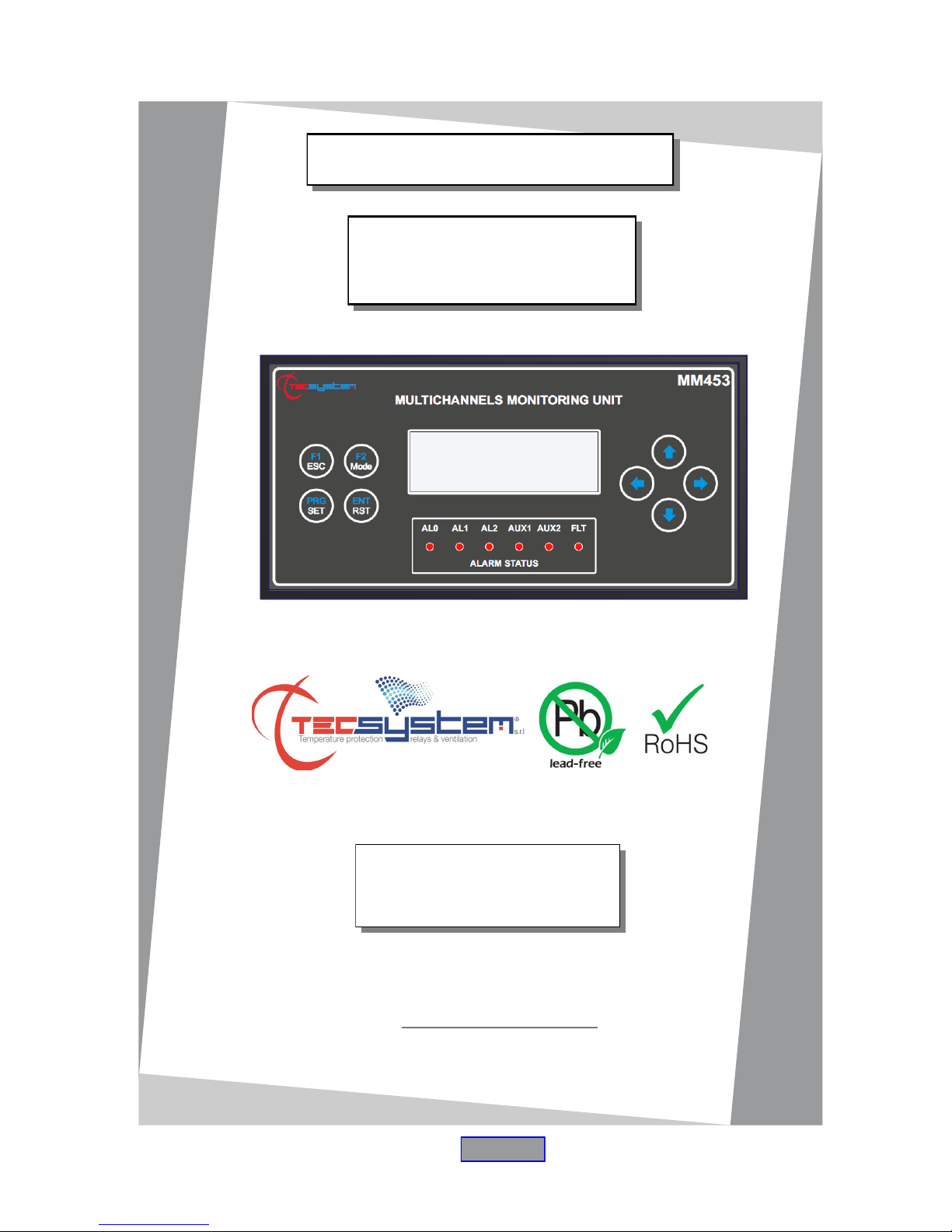
INSTRUCTION MANUAL
MM453
TECSYSTEM S.r.l.
20094 Corsico (MI)
Tel.: +39-024581861
Fax: +39-0248600783
http://www.tecsystem.it
R. 1.2 09/02/17
ENGLISH
1MN0130 REV. 0
operates with ISO9001 certified quality system
“Translations of the original instructions”

2
MM453 SERIES
CONTENTS
PAGE
1) SAFETY REQUIREMENTS
………………………………….. 4
2) ACCESSORIES
………………………………….. 5
3) TECHNICAL SPECIFICATIONS
………………………………….. 6
4) FRONT PANEL
………………………………….. 8
5) MOUNTING
………………………………….. 9
6) ELECTRICAL CONNECTIONS
………………………………….. 10
MM453 BACK
………………………………….. —
POWER SUPPLY
………………………………….. —
WIRING NOTES
………………………………….. 12
PROGRAMMED DATA DIAGNOSTICS
…………………………………... —
SENSOR CONNECTION
………………………………….. —
TEMPERATURE SENSOR DIAGNOSTICS
………………………………….. 13
TEMPERATURE DIAGNOSTICS
………………………………….. —
DISPLAY MODE
………………………………….. —
USE AND WORKING OF MM453 CONTROL UNIT
………………………………….. —
7) PROGRAMMING
………………………………….. 14
PROGRAMMING MENU '
………………………………….. —
PROGRAMMING OF CHANNELS SETTING PAGE
………………………………….. —
PROGRAMMING MM453 SETTING PAGE
………………………………….. 15
FACTORY DEFAULT SELECTION
………………………………….. 16
FACTORY DEFAULT SETTINGS
………………………………….. —
RELAYS LOGIC (AL/AUX).
………………………………….. —
8) MODBUS OPTION
………………………………….. 18
OPERATING NOTES
………………………………….. —
DATA TRANSMISSION ON MODBUS NETWORK
………………………………….. —
RS485 ELECTRICAL CONNECTIONS
………………………………….. —
INTRODUCTION
First of all we wish to thank you for choosing to use a TECSYSTEM product and recommend you read this instruction
manual carefully: You will understand the use of the equipment and therefore be able to take advantage of all its functions.
ATTENTION! THIS MANUAL IS VALID AND COMPLETE FOR THE MM453 / MM453 MODBUS INSIDE /
MM453 AD MONITORING UNIT.

3
MM453 SERIES
PAGE
DATA FRAME
………………………………….. —
DATA PACKET
………………………………….. —
FUNCTION CODE
………………………………….. —
CODE 3(10).
………………………………….. —
CODE 16(10).
………………………………….. 19
NOTES FOR REMOTE PROGRAMMING
………………………………….. —
ERROR CODES (exception code)
………………………………….. —
POLLING FREQUENCY
………………………………….. —
CRC CALCULATION
………………………………….. —
PARAMETER DESCRIPTION
………………………………….. —
ALGORITHM
…………………………………... —
MODBUS PARAMETER PROGRAMMING
………………………………….. 20
MODBUS TEMPERATURE MAPPING
………………………………….. —
CHANNEL STATE AND SETTING MAPPING
………………………………….. 21
AL0 MAPPING
………………………………….. 22
AL1 MAPPING
………………………………….. 23
AL2 MAPPING
………………………………….. 24
121-125 MAPPING
………………………………….. —
9) 4.20mA OUTPUT
………………………………….. 25
10) WARRANTY CONDITIONS
………………………………….. 27
11) TROUBLESHOOTING
………………………………….. 28
12) EQUIPMENT DISPOSAL
………………………………….. —
13) USEFUL CONTACTS
………………………………….. —
4
MM453 SERIES
SAFETY REQUIREMENTS
ATTENTION :
Read the manual carefully before starting to use the control unit. Keep the instructions for future reference.
Do not open the device, touching any internal components can cause electric shock. Contact a voltage over 50
Volts can be fatal. To reduce the risk of electric shock, do not dismantle the back of the device for any reason.
Moreover its opening would void the warranty.
Before connecting the device to the power supply, make sure that all the connections are correct. Always
disconnect the unit from the supply before any cabling modification.
Any work on the equipment must be entrusted to a qualified engineer.
Failure to comply with these instructions can cause damages, fires or electric shock, and possible serious
injuries!
POWER SUPPLY
The MM453 series control unit has UNIVERSAL power supply, i.e. it can be supplied by 24 to 240 Vac-Vdc, irrespectively
of polarity in Vdc.
Before using it, make sure the power cable is not damaged, knotted or pinched. Do not tamper with the power cable.
Never disconnect the unit by pulling the cable, avoid touching the pins. Do not carry out any connecting/disconnecting
with wet hands. To disconnect the device, do not use objects such as levers. Immediately disconnect the device if you
smell burning or see any smoke: contact technical service.
LIQUIDS
Do not expose the equipment to splashes or drops, do not position it in places with humidity exceeding 90% and never
touch with wet or humid hands during storms. If any liquid penetrates the control unit, disconnect it immediately and
contact technical service.
CLEANING
Disconnect the power cable before cleaning the control unit, use a dry cloth to dust it, without any solvent or detergents,
and compressed air.
OBJECTS
Never insert any objects into the cracks of the control unit. If this happens, disconnect the control unit and contact an
engineer.
USE RESERVED TO QUALIFIED PERSONNEL
The purchased goods are a sophisticated electronic device that is totally unsuitable to be used by non-qualified personnel. Any work must be carried out by a specialist engineer.
ACCESSORIES
The use of non-original accessories or spare parts can damage the unit and endanger users' safety. In the event of
faults, contact technical service.
LOCATION
Install the control unit indoors, in a place protected from water splashes and sun rays. Do not place near heat sources
exceeding the parameters stated in this manual. Position on a stable surface, far from any possible vibrations. Position
the unit as far as possible from any intense magnetic fields.
REPAIRS
Do not open the control unit. For any fault, always use qualified personnel. The opening of the control unit and/or the
removal of the series identifying label entails the automatic forfeiture of the warranty. The Warranty seal is applied to all
devices, any attempt to open the unit would break the seal and cause the consequent automatic forfeiture of the
warranty.
TECHNICAL INFORMATION
Mail: ufficiotecnico@tecsystem.it — tel: 02/4581861
5
MM453 SERIES
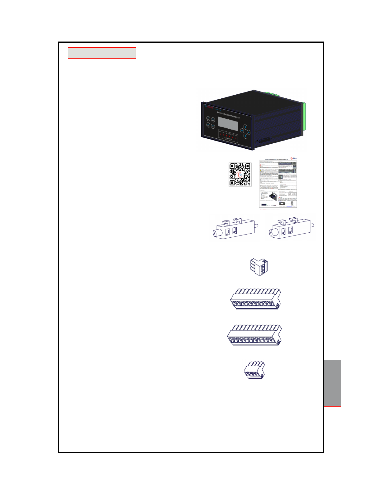
ACCESSORIES
The following objects are present inside the box:
ATTENTION: Always install the device using the terminals included in the pack.
The use of terminals other than those included with the control unit might cause malfunctions.
1MN0030 REV. 0
Control unit
Start Guide and QR code
2 blocks for panel mounting
2/3 supply terminal 3 poles pitch 5 Supply/Relay/RS485
Code: 2PL0367 - Screws tightening torque 0.5Nm
1 relay terminal 15 poles pitch 5
Code:2PL0362 - Screws tightening torque 0.5Nm
1-6 sensor terminal 12 poles pitch 5
Code: 2PL0361- Screws tightening torque 0.5Nm
1 sensor terminal 4.20mA output 4 poles pitch 5
(optional) Code: 2PL0095 - Screws tightening torque
0.5Nm

6
MM453 SERIES
TECHNICAL SPECIFICATIONS
MM453
POWER SUPPLY
Supply rated values 24-240
Vac-Vcc
50/60HZ
Maximum and minimum supply values 20-270
Vac-Vcc
50/60Hz
Vdc with reversible polarities
●
INPUTS
1-24 inputs configurable : sensor inputs RTD Pt100 3-wires
sensor inputs RTD Pt1000 3-wires
sensor inputs TCK
●
Connections on removable terminal strips
●
Input channels protected against electromagnetic interference
●
Cable compensation for Pt100 or Pt1000 500 m (1 mm²)
Compensation for TCK with cable a terminal compensated 100 m
OUTPUTS
5 alarm relays (AL0-AL1-AL2-AUX1-AUX2) SPDT
●
1 sensor or operating failure (FAULT) SPDT
●
Output relays with 5A-250Vca-res COSФ = 1 contacts
●
RS485 Output Modbus RTU
Optional (*)
Scanning 4.20mA output with synchronism signal
Optional (**)
DIMENSIONS
192 x 96-mm DIN43700-depth 220mm (termina l block included) Hole 188 x 92 mm
TESTS AND PERFORMANCE
Construction in compliance with CE regulations
●
Protection from electrical interference EN 61000-4-4
●
Dielectric strength 1500 Vac for 1 min. between output relays and sensors, relays and power supply, power
supply and sensors
●
Accuracy ± 1% full scale value, ± 1 digit
●
Ambient operating temperature from -20 ° C to +60 ° C
●

7
MM453 SERIES
TECHNICAL SPECIFICATIONS
MM453
Front polycarbonate IP54
●
Humidity 90% non-condensing
●
Black anodized aluminum housing
●
Absorption 10VA
●
Data memory 10 years minimum
●
Digital linearity of sensors signal
●
Self-diagnostic circuit
●
Protection treatment of the electronic part Optional
DISPLAY AND DATA MANAGEMENT
1 LCD display with 4 lines of 20 characters to show operative data and program parameters
●
6 LEDs indicated the status of the relay (AL0-AL1-AL2-AUX1-AUX2-FLT)
●
Temperature reading from :-40°C to 240°C PT100
0°C to 300°C PT1000
-40°C to 1000°C TCK
●
Alarm settings from:0°C to 240°C PT100
0°C to 300°C PT1000
0°C to 1000°C TCK
●
3 alarm thresholds for each input
●
Sensor diagnostics (Fcc-Foc)
●
Access to programming through front keyboard
●
Automatic exit from programming after 1 minute’s inactivity
●
Selection between channel automatic scanning, hottest channel or manual scanning
●
Storage of maximum temperatures reached by channels and alarm status (memo)
●
Front key to reset the alarms
●
* Only for Modbus inside and AD versions.
** Olny for AD verdion
8
MM453 SERIES
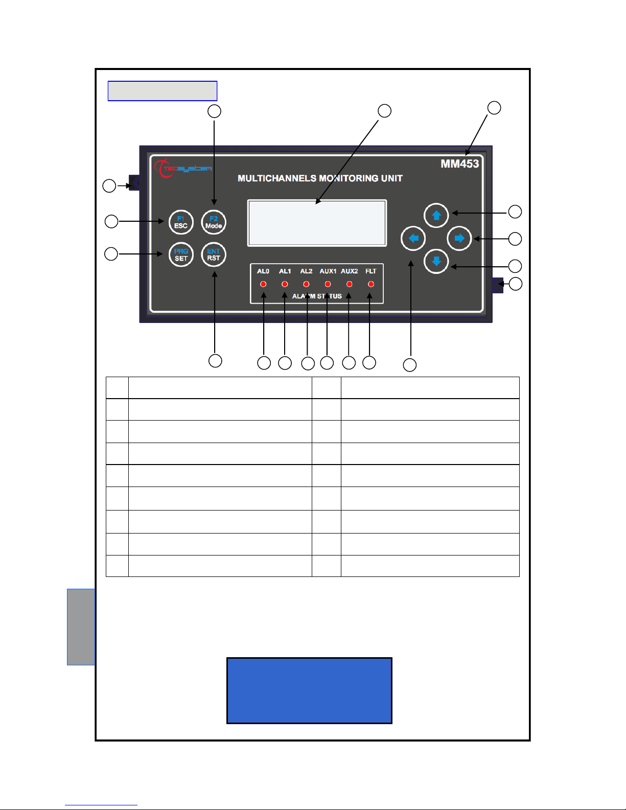
FRONT PANEL
1) LCD display 10) AUX1 relay (red) LED
2) Control unit series 11) AL2 relay (red) LED
3) UP key 12) AL1 relay (red) LED
4) RIGHT key 13) AL0 relay (red) LED
5) DOWN key 14) Enter / Reset key
6) Fixing block 15) Programming / Setting key
7) LEFT key 16) ESC / Functions F1 key
8) Fault relay (red) LED 17) Fixing block
9) AUX2 relay (red) LED 18) Mode / Functions F2 key
1
2
3
4
5
6
7
8 9 10 11 12
14
13
15
16
17
18
1MN0130 REV. 0
NOTE: Due to its own characteristics, the LCD data update speed may be reduced when operating at temperatures lower
than 0°C. Anyway this condition doesn’t affect the correct working of the monitoring unit.
CH 1 2 PT 1 0 0 S C AN
T E M P 23 °C AL 0 O F F
T m a x 1 10 ° C AL 1 O FF
T m i n 8 0 ° C AL 2 O F F
HOME PAGE
SENSOR TYPE CH
CHANNEL CH
TEMPERATURE CH
TEMPERATURE MAX CH
TEMPERATURE MIN CH
SELECTED VIEWING
STATUS AL0
STATUS AL1
STATUS AL2

9
MM453 SERIES
Drill a 188 x 92 mm hole in the panel sheet.
Fix the unit securely with the blocks supplied.
1)
Control unit 3) Fixing screw
2)
Fixing block 4) Cross-head screwdriver # 1X100mm
1
2 3
4
1)
Control unit 2) Panel hole dimensions (± 0.8 mm tolerance )
3)
Identification label
1
MOUNTING
1MN0076 REV. 0
1MN0065 REV. 0
2
3
Note: Do not install the device in too hot or humid places; low frequency and high intensity vibration can cause damage to th e
mechanical structure.

10
MM453 SERIES
ELECTRICAL CONNECTIONS ELECTRICAL CONNECTIONS
1) Pt100 sensors
Card 1 CH1-CH2-CH3-CH4
5) Pt100 sensors
Card 5 CH17-CH18-CH19-CH20
9) AL0 Relay
2) Pt100 sensors
Card 2 CH5-CH6-CH7-CH8
6) Pt100 sensors
Card 6 CH21-CH22-CH23-CH24
10) 4.20mA (Optional) page 25.
3) Pt100 sensors
Card 3 CH9-CH10-CH11-CH12
7) Relays
(AL1-AL2-FAULT-AUX1-AUX2)
11) RS485 (Optional) page 18.
4) Pt100 sensors
Card 4CH13-CH14-CH15-CH16
8) Power Supply (LINE 40-41-42)
24 to 240 Vac-Vcc, 50/60Hz
1) Pt1000 sensors
Card 1 CH1-CH2-CH3-CH4
5) Pt1000 sensors
Card 5 CH17-CH18-CH19-CH20
9) AL0 Relay
2) Pt1000 sensors
Card 2 CH5-CH6-CH7-CH8
6) Pt1000 sensors
Card 6 CH21-CH22-CH23-CH24
10) 4.20mA (Optional) page 25.
3) Pt1000 sensors
Card 3 CH9-CH10-CH11-CH12
7) Relays
(AL1-AL2-FAULT-AUX1-AUX2)
11) RS485 (Optional) page 18.
4) Pt1000 sensors
Card 4CH13-CH14-CH15-CH16
8) Power Supply (LINE 40-41-42)
24 to 240 Vac-Vcc, 50/60Hz
MM453 ex. Pt100
1 2
9
1MN0130 REV. 0
7
PT100 CONNECTION
WHITE
RED
RED
8
3
11
4
5
6
10
MM453 ex. Pt1000
1 2
9
1MN0130 REV. 0
7
WHITE
RED
RED
8
3
11
4
5
6
10
PT1000 CONNECTION

11
MM453 SERIES
Note:the relays status showed when the device is off. When the unit is powered, the FAULT relay switches, contacts 27-28
open (NO) and 26-28 closed (NC), see below image fault contact switching.
FAULT 27-28 NC: ALARM FAULT OR POWER OFF
FAULT 26-28 NC: NO FAULT POWER ON
FAULT CONTACT
26 27 28 26 27 28
POWER SUPPLY
The MM453 control unit has UNIVERSAL power supply, i.e. it can be supplied by 24 to 240 Vac-Vdc, 50/60 Hz irrespectively of polarity in Vdc (terminals 40-42).
This is obtained thanks to the use of a tested power supply unit, newly designed and manufactured, that frees installers
from worrying about the correct Vac and Vdc supply.
The ground must always be connected to terminal 41.
When the unit is supplied directly by the secondary of the transformer to protect, it can be burnt out by strong overvoltages.
This happens if the main switch is closed and the transformer has no load (blank test).
The above-mentioned problems are much more evident when the 220 Vac voltage is taken directly from the
transformer secondary bars and there is a fixed capacitor battery to phase the transformer itself.
1) TCK sensors
Card 1 CH1-CH2-CH3-CH4
5) TCK sensors
Card 5 CH17-CH18-CH19-CH20
9) AL0 Relay
2) TCK sensors
Card 2 CH5-CH6-CH7-CH8
6) TCK sensors
Card 6 CH21-CH22-CH23-CH24
10) 4.20mA (Optional) page 25.
3) TCK sensors
Card 3 CH9-CH10-CH11-CH12
7) Relays
(AL1-AL2-FAULT-AUX1-AUX2)
11) RS485 (Optional) page 18.
4) TCK sensors
Card CH13-CH14-CH15-CH16
8) Power Supply (LINE 40-41-42)
24 to 240 Vac-Vcc, 50/60Hz
MM453 ex. TCK
1 2
9
1MN0130 REV. 0
7
TCK CONNECTION
YELLOW +
RED -
8
3
11
4
5
6
10
PT100-PT1000-TCK INPUTS.
At the customer's specific request you can combine different sensor input cards in the following order
TCK - PT100/PT100 - PT100/PT1000

12
MM453 SERIES
If an existing control unit must be replaced with a new one, to guarantee its correct and safe operation, the sensor/
relay/supply connecting terminals must be replaced with the new terminals supplied.
ATTENTION: the monitoring unit must not be turned off during the starting phase (boot) in order to avoid
configuration data loss. In case of configuration problems, enter in PROGRAMMING and select the option “factory
default” to restore the factory settings.
WIRING NOTES
Connect the terminal on the removable terminal blocks as shown at page 10-11
AL0 alarm relay switches when the set threshold value is reached, enabling is available on all channels, see programming
step 3 on page 14.
AL1-AL2 / AUX1-AUX2 alarm relays switch when the set threshold values are reached according to the selected
intervention logic (Mode Alarm: 1-2-3-4) as shown at page 16-17.
FAULT relay switches when the monitoring unit is powered on and switches back only when the unit has registered one of
the following events:
Data memory fault (message DATA LOST / DATA ERROR) .
Sensors fault (FCC short-circuited sensor, FOC interrupted sensor) .
Insufficient supply voltage
NOTE: do not connect the FAULT relay to the transformer tripping circuit to avoid system interruptions.
The terminals 40-42 must be connected to the phases of power, while the terminal 41 must be connected to the GROUND
of the plant.
NOTE: always disconnect the unit before performing any electrical connection.
PROGRAMMED DATA DIAGNOSTICS
In case of corruption of programmed data, just after switching on, DATA ERROR appears on the display with the relevant
Fault contact. In this case, for safety reasons, the default parameters are loaded automatically (see pre-set default settings
on page 16). Eliminate DATA ERROR by pressing ENT / RST and run programming to enter the desired values.
Finally switch the unit off and back on to check the memory works correctly, if it is damaged DATA ERROR will be
displayed again (send the control unit to Tecsystem srl for repairs).
In case of failure of the internal memory, LOST DATA indication appears with the relevant Fault contact (send the control
unit to Tecsystem srl for repairs).
SENSOR CONNECTION
The PT100 sensors must be connected as shown on page 10-11, each card has 4 inputs.
All the cables transferring the sensors measurement signals must comply with the following under all circumstances:
be separated from the power cable
be made with shielded and twisted conductors
have a minimum cross section of 0.5 mm²
be firmly fixed in the terminal
cables and joints compensated for TCK probes
have tinned or silvered conductors (Pt100-Pt1000)
shielding must be connected with GROUND of the device together with the ground wire.
NOTE: to install the sensors and signal transferring cable correctly, read the sensor and SCS/SENSOR installation
rules manual.
What may happen when installation rules are not complied with.
1)The electrical field propagating from the power line of another circuit, couples capacitively with the conductors
(in particular with unscreened cables). The effect of this coupling creates a signal that overlaps the signal transmitted by
the nearby conductors, causing incorrect readings.
2) The variations in magnetic flux in the power lines may induce an electromotive force on the signal transferring cables
(in particular non-twisted cables), that, being a closed circuit, generates a current. This interference current, multiplied by
the circuit resistance, gives a voltage value that overlaps the signal to be transmitted, distorting the sensor measurement.
3) False contacts can alter the signal with the consequent variation in the temperature detected.
In specific cases, when the rules for connecting the Pt100 sensors are not complied with, the following anomalies can
occur between the SCS box and the temperature control unit:
a) incorrect temperature readings, alarms or anomalous tripping
b) mechanical / electrical fault of the sensors
c) damage to the inputs of the control unit.

13
MM453 SERIES
TECSYSTEM S.r.l. has designed its own special cable to transfer the measurement signals, CEI-compliant, with all
the protection requirements provided for: model CT-ES.
1MN0034 REV. 0
All "M" series control units have linearity of the sensor signal, with a maximum error of 1% of full scale value.
TEMPERATURE SENSOR DIAGNOSTICS
In case of failure or exceeded full scale value of one of the thermometric sensors installed on the machine to protect, the
FAULT relay opens immediately with the relative warning of faulty sensor on the corresponding channel.
Fcc indicates sensor short-circuited or minimum full scale value of the control unit exceeded
Foc indicates sensor interrupted or maximum full scale value of the control unit exceeded
To eliminate the message and reset the opening of the Fault contact, it is necessary to check the Pt100 connections and
replace the faulty sensor (if any). If the minimum/maximum full scale value has been reached, check that the ambient
conditions match the control unit reading.
Note: exceeding the minimum/maximum full scale value can also be caused by interference on the sensor lines; in this
case we recommend that you check: the correct installation of the sensors and above all of the extension cable (as
stated in the paragraph MEASUREMENT SIGNAL TRANSFER)
TEMPERATURE DIAGNOSTICS
When one of the temperature sensors senses a temperature 1°C higher than the alarm threshold, 5 seconds later the
ALARM relay switches and the AL/AUX LED turns on: the page of the channel which generated the alarm displays ON
near the passed threshold (AL0, AL1-AL2 or AUX1-AUX2).
When the taken temperature returns to equal or lower values than the set limit for relay switching, these relays deenergize with consequent turning off of relevant LED.
DISPLAY MODE
Pressing the MODE key, the display modes can be set:
SCAN: the monitoring unit displays a sequence of all activated channels (each 2 seconds)
HIGH: the monitoring unit automatically displays the hottest channel
MAN: manual reading of the channels temperature using the up/down keys
MEMO: the monitoring unit displays the alarm log updated to the last reset. Select the channels through the ▲
▼ keys and press RESET to reset the values.
USE AND OPERATION OF THE MM453 UNIT
The MM453 control unit consists of a system from 1 to 6 Pt100-P1000-TCK interchangeable cards.
Each card has 4 channels: the top card identifies the channels 1-2-3-4, the second 5-6-7-8 channels, the third card 9-1011-12 channels, the fourth 13-14-15-16 channels, the fifth 17-18-19-20 channels, and sixth 21-22-23-24 channels.
NOTE: the use of cables not complying with the above might cause reading anomalies. It is always important to take
into account that any interference on the signal lines might cause anomalies on the Pt100 inputs (CH1-CH2-CH3-
CH4..........................CH24) or on the sensors themselves.
1MN0035 REV. 0

14
MM453 SERIES
CH 12 O N P T 10 0 S ET
A L 0 O N A L 0C 6 0 ° C
R e l A L > A L 1 90°C
M o d e 1 > AL 2 119°C
P R OG R A M M I N G M EN U
1 → C ha n n el s se t ti n g
2 M M 4 5 3 S e t t i n g
3 F a c t or y De f au l t
PROGRAMMING SEQUENCE
MM453
PROGRAMMING MENU
Introduction page to the programming parameters.
PROGRAMMING OF CHANNELS SETTING PAGE
Selecting Channels setting, the page allowing to set the programming parameters for each channel is shown.
FUNCTION DESCRIPTION DISPLAY PAGE
Press and hold the PRG / SET key for 7 seconds until the
PROGRAMMING MENU page is displayed.
Press the ▲▼ keys and place the cursor → on the function desired.
Press the ENT / RST key to confirm your choice.
STEP FUNCTION DESCRIPTION DISPLAY PAGE
1
The cursor → is positioned at the
first available channel.
Press the ▲ ▼ keys to select the page
programming of other channels.
Press the ► key to proceed to step 2.
2
Press the ▲ ▼ keys to enable (ON) or disable
(OFF) the channel.
Press the ► key to proceed to step 3.
3
Press the ▲ ▼ keys to enable (ON) or disable
(OFF) the Alarm AL0 threshold.
Press the ► key to proceed to step 4
(if AL0 ON) or to step 5 if (AL0 OFF).
4
Press the ▲ ▼ keys to set the Alarm AL0 threshold.
Press the ► key to proceed to step 5.
5
Press▲ ▼ keys to select the relay set (AL1-AL2 or
AUX1-AUX2) where 1 and 2 thresholds must be
connected.
Press ► key to proceed to step 6.
CH 1 2 ON P T 1 00 S ET
A L 0 O N A L 0 C 6 0 ° C
R e l A L > A L 1 90°C
M o d e 1 > AL 2 119°C
CH 1 2 O N P T 1 0 0 S E T
A L 0 ON AL 0C 6 0 °C
R e l A L > A L 1 90°C
M o d e 1 > AL 2 119°C
CH 1 2 O N P T 1 0 0 S E T
A L 0 O N A L 0 C 6 0 ° C
R e l A L > A L 1 90°C
M o d e 1 > AL 2 119°C
CH 1 2 O N P T 1 0 0 S E T
A L 0 O N A L 0 C 6 0 ° C
R e l AL > AL 1 90°C
M o d e 1 > AL 2 119°C

15
MM453 SERIES
6
Press the ▲ ▼ keys to set the Alarm AL1
(or AUX1) threshold.
Press the ► key to proceed to step 7.
7
Press ▲ ▼ keys to set the AL1 (or AUX1) relay
intervention logic when the set threshold is
reached.
Mode 1 (>): intervention for T°>threshold
Mode 2 (<): intervention for T°<threshold
Mode 3 (><): intervention for T°<threshold just ex-
ceeded
Mode 4 (><): same logic as mode 3, but with
storage in MEMO page only for the first
alarm occurred among AL1, AL2, AUX1, AUX2
Press ► key to proceed to step 8.
8
Press the ▲ ▼ keys to set the threshold alarm
AL2 (or AUX2).
Press F2 to return to the page PROGRAMMING
MENU
NOTES:
Press the ◄ key to return to the previous step.
Press the F2 key to return to the PROGRAMMING MENU.
Press the F1 key to exit the programming mode if you do not need to set other parameters.
The value of alarm threshold 1 cannot be higher than the threshold value of alarm 2.
CH 1 2 O N P T 1 0 0 S E T
A L 0 O N A L 0 C 6 0 ° C
R e l A L > A L 1 90°C
M o d e 1 > AL 2 119°C
CH 1 2 O N P T 1 0 0 S E T
A L 0 O N A L 0 C 6 0 ° C
R e l A L > A L 1 90°C
M o d e 1 > AL 2 119°C
CH 1 2 O N P T 1 0 0 S E T
A L 0 O N A L 0 C 6 0 ° C
R e l A L > A L 1 90°C
M o d e 1 > AL 2 119°C
PROGRAMMING MM453 PAGE SETTING
Selecting MM453 SETTING it appears the page that allow you to load the MM453 base operating settings.
M M 45 3 S ET T I NG
1 → D is p l ay C on t r as t
- - - -- - - - - - - - -- - - -- - - -
- - - -- - - - - - - - -- - - -- - - -
C O N TR A S T S E T TI N G
■ ■ ■ ■ ■■
0123456789
STEP FUNCTION DESCRIPTION DISPLAY PAGE
1
The cursor → is placed near the setting on which you
want to operate
Press ▲ ▼ keys to change the selection
Press ENTER key to confirm the choice.
NOTE: several optional selections may depend on the
unit model.
2
By selecting Display Contrast the page to
adjust the display contrast is shown.
Press ▲ ▼ keys to modify it.
NOTES:
Press the F2 key to return to the MM453 SETTING
Press the F1 key to exit the programming mode if you do not need to set other parameters.

16
MM453 SERIES
FACTORY DEFAULT SELECTION
Selecting FACTORY DEFAULT the factory settings of the control unit can be restored.
Attention, pressing (yes) all programmed data will be erased and replaced with the default ones.
F A C T OR Y D E F AU L T
R e s et d at a ?
→ no
P r es s E nt e r
STEP FUNCTION DESCRIPTION DISPLAY PAGE
1
Press the ▲ ▼ keys to select yes or no.
Press the ENTER key to confirm your choice.
Setting YES after selecting the default data, the control unit
resets and returns to the display on the screen
“Temperatures”.
NOTES:
Press the F2 key to return to the PROGRAMMING MENU.
Press the F1 key to exit the programming mode and return to display mode temperatures.
FACTORY DEFAULT SETTINGS ALARM AND CONFIGURATION
The selection of the factory default includes:
All channels enable “ON”.
SCAN mode setting.
For the storage of temperature alarms and configuration,
see example screen on the right.
CH 1 2 ON P T 1 00 S ET
A L 0 O N A L 0 C 6 0 ° C
R e l A L > A L 1 90°C
M o d e 1 > AL 2 119°C
RELAYS LOGIC (AL/AUX).
CH 1 2 O N P T 1 0 0 S E T
A L 0 O N A L 0 C 6 0 ° C
R e l A L > A L 1 90°C
M o d e 1 > AL 2 119°C
MM453 PROGRAMMING ALARMS
INDICATION OF OPTIONAL PROGRAM STEPS STATUS ALARM L1 L2
AL1= 90°C - AL2 = 119°C
SWITCHING OVER THE PRESET AL1 and AL2 VALUES 90°C 119°C
CH 1 2 O N P T 1 0 0 S E T
A L 0 O N A L 0 C 6 0 ° C
R e l A L > A L 1 90°C
M o d e 2 > AL 2 119°C
SWITCHING BELOW THE PRESET AL1 VALUE 90 ° C 119 ° C
SWITCHING OVER THE PRESET AL2 VALUE

17
MM453 SERIES
CH 1 2 O N P T 1 0 0 S E T
A L 0 O N A L 0 C 6 0 ° C
R e l A L > A L 1 90°C
M o d e 3 > AL 2 119°C
SWITCHING OVER THE PRESET AL2 VALUE 90 ° C 119 ° C
SWITCHING IF THE VALUE RETURNS BELOW AL1 SET VALUE 90 ° C 119 ° C
MODE 4: In mode 4, the alarm intervention logic is exactly the same as mode 3. The difference is in the all -time alarm
display page (MEMO page): when in mode 4 only the first intervention of one of the following alarms is stored and
displayed :
AL1 or AUX1 (temperature lower than the minimum threshold, with threshold already exceeded)
AL2 or AUX2 (temperature higher than the maximum threshold)
In this case, from the MODE page the first channel triggering the alarm signal can be unequivocally identified.
After the first alarm, the all-time alarm storage in MEMO page is inhibited, but not the interventions and the signal in
SCAN, MAN, HIGH pages. To reset the storage inhibition, press RESET key in MEMO page for all the channels that work
in mode 4.
On the contrary, AL0 and FAULT don’t cause the alarm inhibition. Once it is inhibited, due to the switching of AL1, AL2,
AUX1, AUX2, data are not stored.
ATTENTION: if mode 4 is not reset on all the channels, the monitoring unit will not be able to identify the first
alarm occurred on AL1, AL2, AUX1, AUX2.
NOTE: the alarms are stored in the log after approximately 5 seconds after the triggering of the alarm.
If the monitoring unit is turned off before these 5 seconds, the alarm is not stored in the log.
ATTENTION:
We recommend you to check the programming before starting to use the control unit.
The default parameters set by TECSYSTEM might not suit your requirements.
Programming the device is the end user’s responsibility: the set alarm thresholds and the enabled
functions described in this manual must be checked (by a specialized technician) referring them to the
application and system characteristics on which the control unit is installed.

18
MM453 SERIES
The MM453 Modbus allows to transfer data on a RS485 network with ModBus RTU protocol.
OPERATING NOTES
For a correct working of Modbus it is necessary to load the RS485 network setup parameters: address, baud rate, parity
bit (please refer to Modbus parameter programming at page 20).
The serial communication of the temperature control monitoring unit is active only when the MM453 is in monitoring mode
and not in programming mode.
DATA TRANSMISSION ON MODBUS NETWORK
The Modbus output allows you to read all the data shown in the tables MAP: TEMPERATURE-STATE AND SETTING
CHANNELS and write those indicated in the tables MAP: AL0-AL1-AL2.
The module is always in slave mode.
RS485 ELECTRICAL CONNECTIONS
As far as the signal cable to be used in order to ensure the correct network operation is concerned, we recommend you
follow the provisions of the EIA RS485 standard which suggests using a 24AWG twisted pair.
The twisted pair that connects units in RS485 might need a 120 ohm end resistor on the last unit of the series.
Connect the twisted pair paying attention to polarities and lay the network avoiding to make sharp bends or ring windings
in order not to modify line impedance.
Connection RS485 terminal 61 (-) 62 (+). If necessary, the GND terminal (60) for grounding is also available.
Always position the RS485 twisted pair far from power cables.
DATA FRAME
The frame in asynchronous transmission consists of: 1 start bit, 8 data bits, 1 parity bit (even or odd, if the parity has been
set) and 1 stop bit. Admitted baud rates are: 2400, 4800, 9600 and 19200.
If not otherwise specified, the word length (DATA) is 16 bits.
DATA PACKET
A complete sequence of request/answer consists of the following:
Master request:
SLAVE ADDRESS - 1 byte
FUNCTION CODE - 1 byte
DATA - variable, it depends by function code
CRC - 2 bytes
Slave request:
SLAVE ADDRESS - 1 byte
FUNCTION CODE - 1 byte
DATA - variable, it depends by function code
CRC - 2 bytes
FUNCTION CODE
The MM453 ModBus module supports the following function codes:
3
(10)
: - holding register reading
16
(10)
: - register multiple writing
If MODBUS receives a message and a CRC error is detected, no answer is given.
CODE 3
(10)
.
Request:
Slave address, code 3
(10)
, Starting address HI, Starting address LO, Number of Point HI, Number of Point LO, Crc LO, Crc
HI.
Answer:
Slave address, code 3
(10)
, Byte count, Data HI, Data LO……., Crc LO, Crc HI.
OPZIONE MODBUS

19
MM453 SERIES
CODE 16
(10)
.
Request:
Slave address, code 16
(10)
, Starting address HI, Starting address LO, Number of Point HI, Number of Point LO, Byte
count, Data HI, Data LO……., Crc LO, Crc HI.
Answer:
Slave address, code 16
(10)
, Starting address HI, Starting address LO, Number of Register HI, Number of register LO, Crc
LO, Crc HI.
The writable registers are the ones containing the following data: AL0, AL1, AL2.
Therefore the possible starting address are: 49-72 for AL0 thresholds, 73-96 for AL1 thresholds, 97-120 for AL2
thresholds. Number of Point LO parameter can be loaded from 1 to 24 (max).
If a writing request is sent to an address different from the above mentioned ones, MODBUS will answer with a 02 error
code (wrong data address).
If a writing request for a number higher than 24 registers is sent (Number of point LO), MODBUS won’t be able to accept
the request and it won’t give any answer. Therefore the query will go in “timeout”.
NOTES FOR REMOTE PROGRAMMING
Also in the remote programming phase via ModBus you must take into consideration that AL1 thresholds must be lower
than AL2 thresholds.
In case you try to set these thresholds incorrectly, the control unit will not proceed with the programming and
storage of data, therefore in subsequent readings will read the data from the previous schedule.
ERROR PROGRAMMING message will be displayed for 2 seconds.
After having sent a request for writing the control unit will take a time of about 1 to store the data in eeprom, during the
storage. To confirm the display will show REMOTE PROGRAMMING message.
ERROR CODES (exception code).
In case of a wrong request, MM453 will answer with modified codes and codified errors according to the following:
1: - Unsupported function code
2: - Wrong data address
3: - Wrong data (for instance length)
POLLING FREQUENCY
We recommend polling frequencies equal to or greater than 1 second are adopted.
More frequent polling can overload the system without any benefit whatsoever.
CRC CALCULATION
The protocol includes 2 CRC-16 bytes in each transmission. The characteristic polynomial (11000000000000101B) is
used for the calculation and the result is “hung” at the end of the packet. The polynomial is used in reverse order
with the most significant bit suppressed because useless for the purpose of the calculation.
PARAMETER DESCRIPTION
A - 16-bit registers
AL – A low part
AH – A high part
i,j, - COUNTERS
(+) - EXCLUSIVE OR
Di - Datum of the «i»th of the packet
N - number of bytes in the packet excluded 2 of the CRC
G - Polynomial : 1010-0000-0000-0001
shr - shift to the right
ALGORITHM
0xFFFF -> A
0 -> i
0 -> j
Di (+) AL -> AL
j +1 -> j
shr A
if carry then G (+) A -> A
if NOT j=8 then go to 5
i +1 -> i
if NOT i = N then go to 3
11) A -> in CRC (the result is in order L,H)

20
MM453 SERIES
MODBUS PARAMETER PROGRAMMING (only for MODBUS version)
Introduction page to the monitoring unit programming parameters
Selecting MM453 SETTING, the page allowing to load the operational settings for the base unit MM453 is displayed.
MODBUS TEMPERATURE MAPPING
STEP FUNCTION DESCRIPTION PAGE DISPLAY
1
Position cursor → on Modbus setting.
Press ▲ ▼ keys to change the selection.
Press ENTER key to confirm the choice.
2
Selecting Modbus Setting the page allowing to load
the Modbus parameter setting is displayed.
Press ◄ ► keys to select the parameter to modify
(ADR= address, Bdr= Baud rate, PAR= parity bit).
Press ▲ ▼ keys to modify it.
NOTES:
Press F2 key to return to MM453 SETTING page.
Press F1 key to leave the programming if you don’t need to load other parameters.
M O D B U S S E T T IN G
A D R → 0 1
B d r 9600
P A R N ON E
FUNCTION DESCRIPTION PAGE DISPLAY
Keep pressed PRG/SET key for 7 seconds until
PROGRAMMING MENU page appears.
Press ▲ ▼ keys and move the cursor → o n MM453 Setting
function.
Press ENT/RST key to confirm the choice.
P R O G RA M M I NG M E N U
1 Ch an n e ls s e t t in g
2 → M M 45 3 S e tt i n g
3 Fa ct o r y D e f a u lt
M M 4 5 3 S E T T IN G
1 D is p l a y C o n t ra s t
2 → M o d bu s s e tt i n g
3 F ac t o ry d e fa ul t
ADR_HI ADR_LO DATA_HI DATA_LO PRIMARY TABLES
0 1 TEMP_HI_CH1 TEMP_LO_CH1 HOLDING REGISTER
0 2 TEMP_HI_CH2 TEMP_LO_CH2 HOLDING REGISTER
0 3 TEMP_HI_CH3 TEMP_LO_CH3 HOLDING REGISTER
0 4 TEMP_HI_CH4 TEMP_LO_CH4 HOLDING REGISTER
0 5 TEMP_HI_CH5 TEMP_LO_CH5 HOLDING REGISTER
0 6 TEMP_HI_CH6 TEMP_LO_CH6 HOLDING REGISTER
0 7 TEMP_HI_CH7 TEMP_LO_CH7 HOLDING REGISTER
0 8 TEMP_HI_CH8 TEMP_LO_CH8 HOLDING REGISTER
0 9 TEMP_HI_CH9 TEMP_LO_CH9 HOLDING REGISTER
0 10 TEMP_HI_CH10 TEMP_LO_CH10 HOLDING REGISTER
0 11 TEMP_HI_CH11 TEMP_LO_CH11 HOLDING REGISTER
0 12 TEMP_HI_CH12 TEMP_LO_CH12 HOLDING REGISTER
0 13 TEMP_HI_CH13 TEMP_LO_CH13 HOLDING REGISTER
0 14 TEMP_HI_CH14 TEMP_LO_CH14 HOLDING REGISTER
0 15 TEMP_HI_CH15 TEMP_LO_CH15 HOLDING REGISTER
0 16 TEMP_HI_CH16 TEMP_LO_CH16 HOLDING REGISTER

21
MM453 SERIES
Registers from N.1 to N.24 contain the values relevant to each channel.
In order to manage also the reading of the negative quantities and to get the correctly shifter item you have to subtract
an offset of 160 to the read value.
To the Fault Foc (fault for “open” sensor “) and Fcc (fault for short circuited sensor) conditions, correspond the following
messages (which have not a numerical meaning in terms of temperature):
FOC: 1024 (0x2800 hex)
FCC: 10 (0x000A hex)
ADR_HI ADR_LO DATA_HI DATA_LO PRIMARY TABLES
0 17 TEMP_HI_CH17 TEMP_LO_CH17 HOLDING REGISTER
0 18 TEMP_HI_CH18 TEMP_LO_CH18 HOLDING REGISTER
0 19 TEMP_HI_CH19 TEMP_LO_CH19 HOLDING REGISTER
0 20 TEMP_HI_CH20 TEMP_LO_CH20 HOLDING REGISTER
0 21 TEMP_HI_CH21 TEMP_LO_CH21 HOLDING REGISTER
0 22 TEMP_HI_CH22 TEMP_LO_CH22 HOLDING REGISTER
0 23 TEMP_HI_CH23 TEMP_LO_CH3 HOLDING REGISTER
0 24 TEMP_HI_CH24 TEMP_LO_CH4 HOLDING REGISTER
ADR_HI ADR_LO DATA_HI DATA_LO PRIMARY TABLES
0 25 STATO_AL_CH1 SETTING_CH1 HOLDING REGISTER
0 26 STATO_AL_CH2 SETTING_CH2 HOLDING REGISTER
0 27 STATO_AL_CH3 SETTING_CH3 HOLDING REGISTER
0 28 STATO_AL_CH4 SETTING_CH4 HOLDING REGISTER
0 29 STATO_AL_CH5 SETTING_CH5 HOLDING REGISTER
0 30 STATO_AL_CH6 SETTING_CH6 HOLDING REGISTER
0 31 STATO_AL_CH7 SETTING_CH7 HOLDING REGISTER
0 32 STATO_AL_CH8 SETTING_CH8 HOLDING REGISTER
0 33 STATO_AL_CH9 SETTING_CH9 HOLDING REGISTER
0 34 STATO_AL_CH10 SETTING_CH10 HOLDING REGISTER
0 35 STATO_AL_CH11 SETTING_CH11 HOLDING REGISTER
0 36 STATO_AL_CH12 SETTING_CH12 HOLDING REGISTER
0 37 STATO_AL_CH13 SETTING_CH13 HOLDING REGISTER
0 38 STATO_AL_CH14 SETTING_CH14 HOLDING REGISTER
0 39 STATO_AL_CH15 SETTING_CH15 HOLDING REGISTER
0 40 STATO_AL_CH16 SETTING_CH16 HOLDING REGISTER
0
41 STATO_AL_CH17 SETTING_CH17 HOLDING REGISTER
0
42 STATO_AL_CH18 SETTING_CH18 HOLDING REGISTER
0
43 STATO_AL_CH19 SETTING_CH19 HOLDING REGISTER
0
44 STATO_AL_CH20 SETTING_CH20 HOLDING REGISTER
0
45 STATO_AL_CH21 SETTING_CH21 HOLDING REGISTER
0
46 STATO_AL_CH22 SETTING_CH22 HOLDING REGISTER
0
47 STATO_AL_CH23 SETTING_CH23 HOLDING REGISTER
0
48 STATO_AL_CH24 SETTING_CH24 HOLDING REGISTER
CHANNEL STATE AND SETTING MAPPING
Registers from N.25 to N.48 contain the state of the channels in the higher side and the setting in the lower side.

22
MM453 SERIES
STATE_AL_CHn (0 = off, 1 = on)
bit 0: AL0
bit 1: AL1
bit 2: AL2
bit 3: AUX1
bit 4: AUX2
bit 5: FAULT
bit 6: (free)
bit 7: (free)
SETTING_CHn (0 = off, 1 = on)
bit 0: Ch enabled
bit 1: AL0 enabled
bit 2: AL1-AL2 relays enabled
bit 3: AUX1-AUX2 relays enabled
bit 4: Present channel (connected card)
bit 5: (free)
bit 6: (free)
bit 7: Modified channel (system data)
STATE_AL_CHn SETTING_CHn
bit7 bit6 bit5 bit4 bit3 bit2 bit1 bit0 bi t7 bi t6 bit5 bit4 bit3 bit2 bit1 bit0
(free) (free) FAULT AUX2 AUX1 AL2 AL1 AL0
Ch
modified
(free) (free)
Ch
present
AUX1-2
enabled
AL1-2
enabled
AL0
enabled
Ch
enabled
AL0 MAPPING
Registers from N.49 to N.72 contain the AL0 thresholds programmed for each channel.
In order to manage also the reading of the negative values is necessary to subtract an offset of 160 to calculate the
correct data.
ADR_HI ADR_LO DATA_HI DATA_LO PRIMARY TABLES
0 49 AL0_HI_CH1 AL0_LO_CH1 HOLDING REGISTER
0 50 AL0_HI_CH2 AL0_LO_CH2 HOLDING REGISTER
0 51 AL0_HI_CH3 AL0_LO_CH3 HOLDING REGISTER
0 52 AL0_HI_CH4 AL0_LO_CH4 HOLDING REGISTER
0 53 AL0_HI_CH5 AL0_LO_CH5 HOLDING REGISTER
0 54 AL0_HI_CH6 AL0_LO_CH6 HOLDING REGISTER
0 55 AL0_HI_CH7 AL0_LO_CH7 HOLDING REGISTER
0 56 AL0_HI_CH8 AL0_LO_CH8 HOLDING REGISTER
0 57 AL0_HI_CH9 AL0_LO_CH9 HOLDING REGISTER
0 58 AL0_HI_CH10 AL0_LO_CH10 HOLDING REGISTER
0 59 AL0_HI_CH11 AL0_LO_CH11 HOLDING REGISTER
0 60 AL0_HI_CH12 AL0_LO_CH12 HOLDING REGISTER
0 61 AL0_HI_CH13 AL0_LO_CH13 HOLDING REGISTER
0 62 AL0_HI_CH14 AL0_LO_CH14 HOLDING REGISTER
0 63 AL0_HI_CH15 AL0_LO_CH15 HOLDING REGISTER
0 64 AL0_HI_CH16 AL0_LO_CH16 HOLDING REGISTER
0 65 AL0_HI_CH17 AL0_LO_CH17 HOLDING REGISTER
0 66 AL0_HI_CH18 AL0_LO_CH18 HOLDING REGISTER
0 67 AL0_HI_CH19 AL0_LO_CH19 HOLDING REGISTER
0 68 AL0_HI_CH20 AL0_LO_CH19 HOLDING REGISTER
0 69 AL0_HI_CH21 AL0_LO_CH20 HOLDING REGISTER
0 70 AL0_HI_CH22 AL0_LO_CH21 HOLDING REGISTER
0 71 AL0_HI_CH23 AL0_LO_CH22 HOLDING REGISTER
0 72 AL0_HI_CH24 AL0_LO_CH23 HOLDING REGISTER

23
MM453 SERIES
AL1 MAPPING
ADR_HI ADR_LO DATA_HI DATA_LO PRIMARY TABLES
0 73 AL1_HI_CH1 AL1_LO_CH1 HOLDING REGISTER
0 74 AL1_HI_CH2 AL1_LO_CH2 HOLDING REGISTER
0 75 AL1_HI_CH3 AL1_LO_CH3 HOLDING REGISTER
0 76 AL1_HI_CH4 AL1_LO_CH4 HOLDING REGISTER
0 77 AL1_HI_CH5 AL1_LO_CH5 HOLDING REGISTER
0 78 AL1_HI_CH6 AL1_LO_CH6 HOLDING REGISTER
0 79 AL1_HI_CH7 AL1_LO_CH7 HOLDING REGISTER
0 80 AL1_HI_CH8 AL1_LO_CH8 HOLDING REGISTER
0 81 AL1_HI_CH9 AL1_LO_CH9 HOLDING REGISTER
0 82 AL1_HI_CH10 AL1_LO_CH10 HOLDING REGISTER
0 83 AL1_HI_CH11 AL1_LO_CH11 HOLDING REGISTER
0 84 AL1_HI_CH12 AL1_LO_CH12 HOLDING REGISTER
0 85 AL1_HI_CH13 AL1_LO_CH13 HOLDING REGISTER
0 86 AL1_HI_CH14 AL1_LO_CH14 HOLDING REGISTER
0 87 AL1_HI_CH15 AL1_LO_CH15 HOLDING REGISTER
0 88 AL1_HI_CH16 AL1_LO_CH16 HOLDING REGISTER
0 89 AL1_HI_CH17 AL1_LO_CH17 HOLDING REGISTER
0 90 AL1_HI_CH18 AL1_LO_CH18 HOLDING REGISTER
0 91 AL1_HI_CH19 AL1_LO_CH19 HOLDING REGISTER
0 92 AL1_HI_CH20 AL1_LO_CH20 HOLDING REGISTER
0 93 AL1_HI_CH21 AL1_LO_CH21 HOLDING REGISTER
0 94 AL1_HI_CH22 AL1_LO_CH22 HOLDING REGISTER
0 95 AL1_HI_CH23 AL1_LO_CH23 HOLDING REGISTER
0 96 AL1_HI_CH24 AL1_LO_CH24 HOLDING REGISTER
Registers from N.73 to N.96 contain the AL1 thresholds programmed for each channel.
In order to manage also the reading of the negative values is necessary to subtract an offset of 160 to calculate the correct
data.

24
MM453 SERIES
AL2 MAPPING
Registers from N.97 to N.120 contain the AL2 thresholds programmed for each channel.
In order to manage also the reading of the negative values is necessary to subtract an offset of 160 to calculate the
correct data.
ADR_HI ADR_LO DATA_HI DATA_LO REGISTRO
0 121 ADR MODBUS BDR WORD_120
0 122 PARITY free WORD_121
0 123 COMMAND_HI COMMAND_LO WORD_122
0 124 free free WORD_123
0 125 free free WORD_124
MAPPING 121 125.
By sending to the register 123 a writing command (CODE16) containing 00000000 – 00000001 word, a remote reset
procedure is activated, whose aim is to reset the log of the alarms and the min. and max. recorded temperatures stored
in the unit. REMOTE RESET message confirms that the command has been executed.
At the moment the registers 122_LO and registers from 124 to 125 are not used.
ADR MODBUS BDR
bit7 bit6 bit5 bit4 b it3
bit2 bit1 bi t0 bit7 bit6 bi t5 bit4 bit3 bit2 bit1 bit0
adr_07 adr_06 adr_05 adr_04 adr_03 adr_02 adr_01 adr_01
0 0 0 0 0 0 BDR1 BDR0
ADR_HI ADR_LO DATA_HI DATA_LO PRIMARY TABLES
0 97 AL2_HI_CH1 AL2_LO_CH1 HOLDING REGISTER
0 98 AL2_HI_CH2 AL2_LO_CH2 HOLDING REGISTER
0 99 AL2_HI_CH3 AL2_LO_CH3 HOLDING REGISTER
0 100 AL2_HI_CH4 AL2_LO_CH4 HOLDING REGISTER
0 101 AL2_HI_CH5 AL2_LO_CH5 HOLDING REGISTER
0 102 AL2_HI_CH6 AL2_LO_CH6 HOLDING REGISTER
0 103 AL2_HI_CH7 AL2_LO_CH7 HOLDING REGISTER
0 104 AL2_HI_CH8 AL2_LO_CH8 HOLDING REGISTER
0 105 AL2_HI_CH9 AL2_LO_CH9 HOLDING REGISTER
0 106 AL2_HI_CH10 AL2_LO_CH10 HOLDING REGISTER
0 107 AL2_HI_CH11 AL2_LO_CH11 HOLDING REGISTER
0 108 AL2_HI_CH12 AL2_LO_CH12 HOLDING REGISTER
0 109 AL2_HI_CH13 AL2_LO_CH13 HOLDING REGISTER
0 110 AL2_HI_CH14 AL2_LO_CH14 HOLDING REGISTER
0 111 AL2_HI_CH15 AL2_LO_CH15 HOLDING REGISTER
0 112 AL2_HI_CH16 AL2_LO_CH16 HOLDING REGISTER
0 113 AL2_HI_CH17 AL2_LO_CH17 HOLDING REGISTER
0 114 AL2_HI_CH18 AL2_LO_CH18 HOLDING REGISTER
0 115 AL2_HI_CH19 AL2_LO_CH19 HOLDING REGISTER
0 116 AL2_HI_CH20 AL2_LO_CH20 HOLDING REGISTER
0 117 AL2_HI_CH21 AL2_LO_CH21 HOLDING REGISTER
0 118 AL2_HI_CH22 AL2_LO_CH22 HOLDING REGISTER
0 119 AL2_HI_CH23 AL2_LO_CH23 HOLDING REGISTER
0 120 AL2_HI_CH24 AL2_LO_CH24 HOLDING REGISTER

25
MM453 SERIES
Available ADR MODBUS:
adr_07…adr_00 = from 00000000 (0) to 11111111 (255)
BDR available values:
BDR1 BDR0 = 00 2400 B/S
BDR1 BDR0 = 01 4800 B/S
BDR1 BDR0 = 10 9600 B/S
BDR1 BDR0 = 11 19200 B/S
bit2…bit7 = not used
PARITY available values:
par_1 par_2 = 00 NONE
par_1 par_2 = 01 EVEN
par_1 par_2 = 10 ODD
bit2…bit7 = not used
PARITY
bit7 bit6 bit5 bit4 bit3
bit2 bit1 bit0
0 0 0 0 0 0 par_1 par_2
4-20mA OUTPUT
Formula to calculate the current (mA) having
temperature:
Formula to calculate the temperature from the
current ( mA):
15
4
240
16
4
Temp
TempI
154 ITemp
OUTPUT VALUES 4.20mA- CARD PT100
Range: 4-20mA 0 to 240 ° C
Accuracy: ± 0.5% V.f.s.
As showed in the 4-20mA table output refers only to positive values of temperature. In case the reading of the
control unit is lower then: 0° C, the output indicated 4mA (value corresponding to 0 ° C, common to all 3 types of
card).
Below you will find the formula to calcolate the temperature of the current value
CARD TEMPERATURE RANGE
PT100 0-240°C
PT1000 0-300°C
TCK 0-1000°C
These values in common for three different types of cards: Pt100, Pt1000, Tck.
The output range is different according to the type of card:
FUNCTION 4-20mA Output
Disabled channel 0mA
Channel ERROR (card not working) 2mA
Channel FCC 3mA
Channel FOC 21mA
The MM453 unit has a 4.20mA signal output with current scanning. The scan duration is two seconds for each channel,
for all channels (including those are turned off).
OUTPUT 4.20mA VALUES - MESSAGES - TEMPERATURE
26
MM453 SERIES
4.20mA OUTPUT VALUES – PROGRAMMING MODE
When the unit enters in "programming mode " (PRG button pressed for more than 8 seconds) 420mA output
reset and the opto-isolator is placed in a "run mode". This condition remains until the unit is in programming
mode.
CHANNEL SCANNING
Scanning time is 2 seconds for each channel, and is performed on all channels (including channels then turned
off). For example if a unit MM453 is equipped with 4 cards the scan will cover 16 channels, and the routine timing
is 32 seconds to perform a cycle.
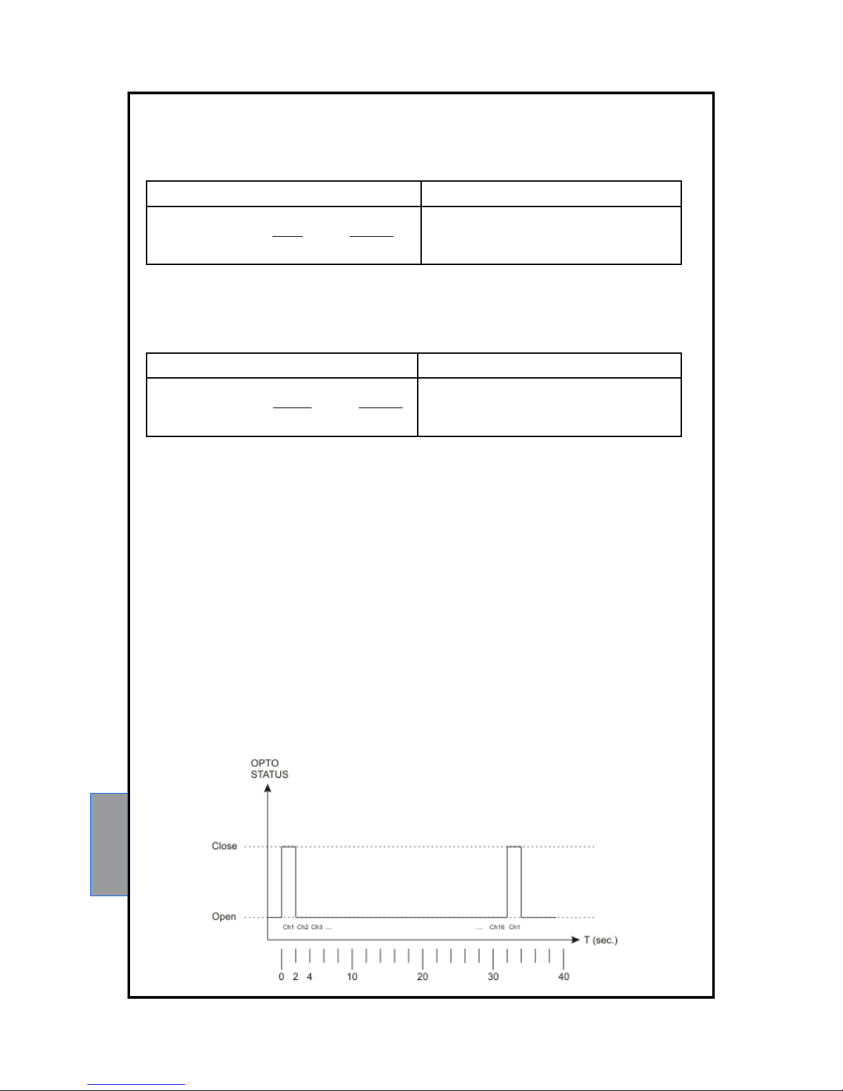
OUT OF SYNC – Optocoupler (Opto-isolator)
The output synchronization consists of an optoisolator (Emitter - Collector) that allows you to "synchronize" the
reading instrument 4-20mA channel to the analog output of the unit.
During the scan cycle, the phototransistor remains in conduction only for the two seconds relative to the scanning
of the first channel, while it remains interdicted during scanning of all the other n-channels.
The following graph show an example of the timing of a scan on a unit with 4 cards (16 channels).
4.20mA OUTPUT VALUES - CARD Tck
Range: 4-20mA 0 to 1000 ° C
Accuracy: ± 0.5% V.f.s.
Formula to calculate the current (mA) having
temperature:
Formula to calculate the temperature from the
current ( mA):
5.62
4
1000
16
4
Temp
TempI
5.624 ITemp
Formula to calculate the current (mA) having
temperature:
Formula to calculate the temperature from the
current ( mA):
75.18
4
300
16
4
Temp
TempI
75.184 ITemp
4.20mA OUTPUT VALUES – CARD PT1000
Range: 4-20mA 0 to 300 ° C
Accuracy: ± 0.5% V.f.s.

27
MM453 SERIES
WARRANTY CONDITIONS
The Product purchased is covered by the manufacturer's or seller's warranty at the terms and conditions set forth in
the "Tecsystem s.r.l's General Conditions of Sale", available at www.tecsystem.it and / or in the purchase agreement.
The warranty is considered valid only when the product is damaged by causes attributable to TECSYSTEM srl, such
as manufacturing or components defects.
The warranty is invalid if the Product proves to have been tampered with / modified, incorrectly connected, because of
voltages outside the limits, non-compliance with the assembly and use technical data, as described in this
instruction manual.
The warranty is always ex Corsico as stated in the "General Conditions of Sale".
4.20mA SPECIFICATIONS OUTPUT
Output active loop current, maximum load impedance of 500 ohms.
Optocoupler SPECIFICATIONS OUTPUT
Output emitter - collector
Maximum applicable voltage VCE 70V
Maximum collector current Ic 1.5mA
Minimum load resistance 3.5 kOhm (5V)
REAR PANEL ELECTRICAL CONNECTIONS: SECTION MODBUS AND 4.20mA
RS485 and the 4.20mA outputs must be connected as shown in the above wiring diagram, using a twisted and
shielded cable designed to transfer signals.

28
MM453 SERIES
TECHNICAL INFORMATION: ufficiotecnico@tecsystem.it
COMMERCIAL INFORMATION: info@tecsystem.it
USEFUL CONTACTS
TROUBLESHOOTING
CAUSES AND SOLUTIONS
The control unit does not switch on and the
supply to terminals 40-42 is correct.
Check that: the connector is correctly inserted into its housing, the
wires are tightened, there is no evidence of burning on the
connectors. Disconnect the power supply, carry out the above and
reconnect.
One of the channels is in FAULT due to
FOC/FCC
Check the connections of the sensors, check the instructions given
in the paragraphs: sensor connection on page 12.
When turning on, the display shows
“DATA ERROR” or “DATA LOST”
Strong interference damaged the stored data. See the paragraph
Programmed data diagnostics on page 12.
All the sensors are in FCC.
Incorrect sensor connection, the terminal block has been inserted
upside down. Check the connections and the terminal board.
The temperature shown by one or more
channels is wrong.
Contact the TECSYSTEM Technical Department.
Sudden trip of the main switch. The temperature
is on standard levels. Just one channel has
caused the trip.
Verify through MEMO function possible defective sensors. Replace
the sensor. Check the measuring signal support terminal boards.
Contact TECSYSTEM Technical Department if the problem persists.
EQUIPMENT DISPOSAL
European directives 2012/19/EC (WEEE) and 2011/65/EC (RoHS) have been approved to reduce electrical and electronic waste and promote the recycling and reuse of the materials and components of said equipment, cutting down on
the disposal of the residues and harmful components of electrical and electronic materials.
All the electrical and electronic equipment supplied after 13 August 2005 is marked with this symbol, pursuant
to European directive 2002/96/EEC on electrical and electronic waste (WEEE). Any electrical or electronic
equipment marked with this symbol must be disposed of separately from normal domestic waste.
Returning used electrical devices: contact TECSYSTEM or your TECSYSTEM agent for information on the correct
disposal of the devices.
TECSYSTEM is aware of the impact its products have on the environment and asks its customers active support in
the correct and environmentally-friendly disposal of its devices.
 Loading...