

Page 1

C329-SPI-CO_UM_EN_20141014_RH
TecSys GmbH •••• Karl-Theodor-Str. 55 •••• D– 80803 München •••• Tel +49 89 321 990-0 •••• www.tecsys.de
C329-SPI User Manual
Release Note:
V1.0 27th September 2010 First release
V1.1 12th January 2012 Second release
Page 2
C329-SPI-CO_UM_EN_20141014_RH
TecSys GmbH •••• Karl-Theodor-Str. 55 •••• D– 80803 München •••• Tel +49 89 321 990-0 •••• www.tecsys.de
General Description
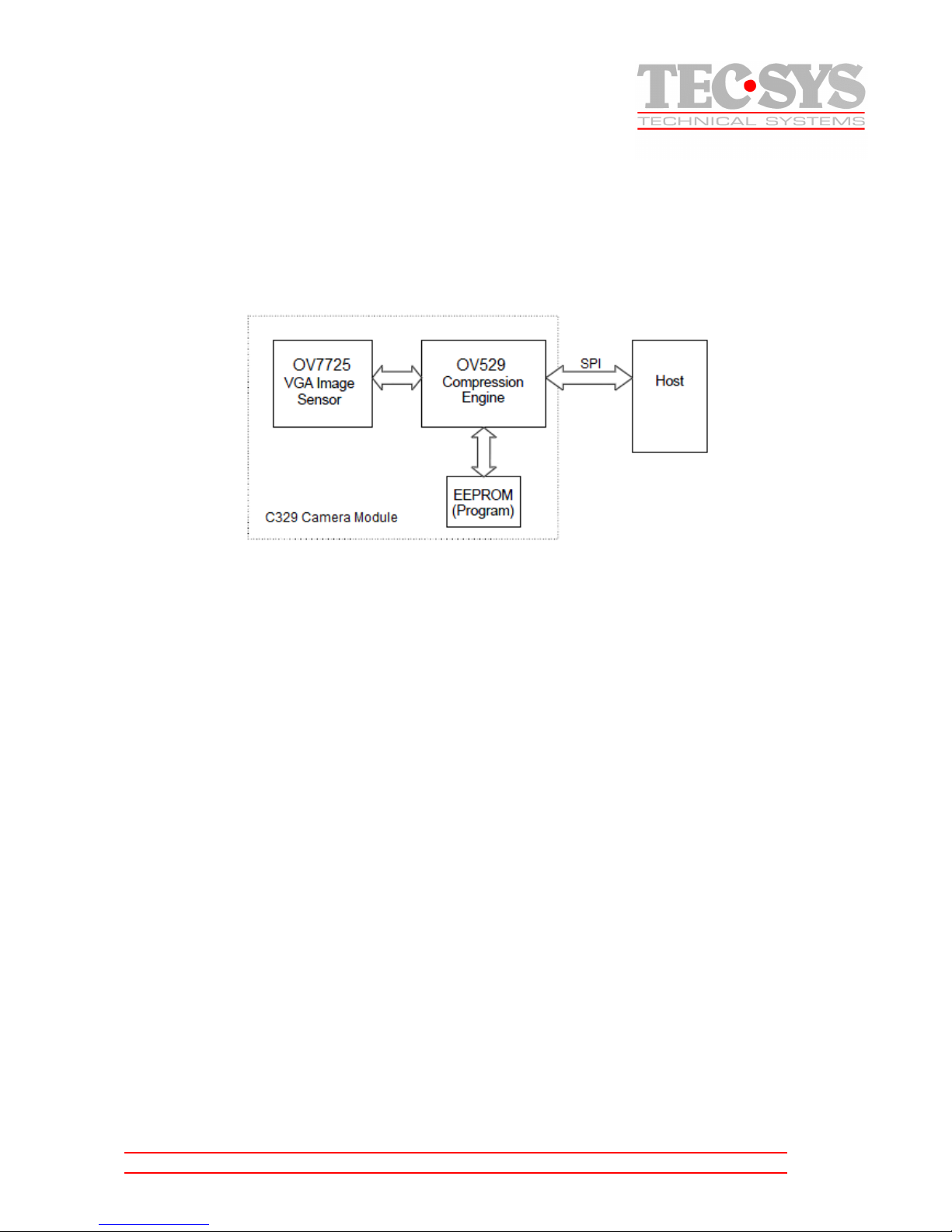
The C329 is a colour VGA camera module which performs JPEG compression and can be attached
to a host via an SPI interface. Users can send a Snapshot command from the host in order to capture
an image. The image is then compressed by the host and stored in and internal buffer and
transferred to the host through the SPI port.
Figure 1 – System Block Diagram
Features
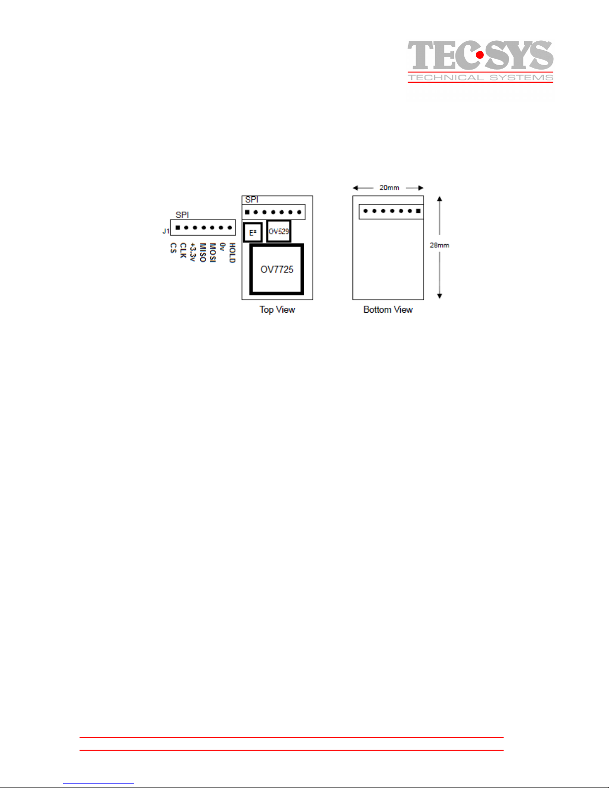
• Small Size, 20x28mm
• Adjustable resolution resolution, Max VGA
• 3.3V operation
• Low Power consumption 64mA active
• SPI Interface with Hold
• Power Saving Mode
• Multiple lens options
• Multiple interface options (UART version available)
System Configuration
Camera Sensor
The C329 uses a 1/4" OmniVision VGA sensor with an 8-bit YcbCr interface and 3.8 V/(Lux Sec)
sensitivity.
OV529 Serial Bridge
The OV529 Serial bridge contains an Embedded JPEC CODEC and controller chip that can
compress and transfer image data from the Camera Sensor to an external device. The OV529
performs all imaging functions like white balance, downsizing and compressed image storage.
Page 3
C329-SPI-CO_UM_EN_20141014_RH
TecSys GmbH •••• Karl-Theodor-Str. 55 •••• D– 80803 München •••• Tel +49 89 321 990-0 •••• www.tecsys.de
Program EEPROM
A Serial EEPROM provides the program code that gives the OV529 it's interface and command set.
Board Layout
Figure 2 – C329-SPI board Layout and Serial Interface
SPI Interface
Timing Options and CLK
The SPI interface consists of MOSI (Master Out Slave In), MISO (Master In Slave Out), CLK and
CS. In the OV529 there is the addition of HOLD which when H indicates to the Master that the
OV529 isn't ready and should hold off the next transaction. The CS signal allows multiple devices
to be attached to the SPI bus. When CS is L the OV529 is selected. Data on MISO will be clocked
out on the falling edge of CLK and data on MOSI will be clocked in on the rising edge of CLK. (It
is possible to select both clock edges, this will require a hardware change that must be ordered
specifically. It is recommended to use the above scenario if at all possible)
Page 4
C329-SPI-CO_UM_EN_20141014_RH
TecSys GmbH •••• Karl-Theodor-Str. 55 •••• D– 80803 München •••• Tel +49 89 321 990-0 •••• www.tecsys.de
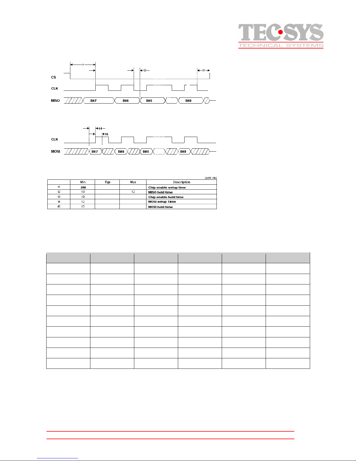
Figure 3 – SPI Timing
Command Set
The C329-SPI module supports the following commands:
Command
Cmd Token
Parameter 1
Parameter 2
Parameter 3
Parameter 4
INITIAL FFFFFF01h 00h Colour Type Preview Res. Compres. Res
GET PIC FFFFFF04h Pic. Type 00h 00h 00h
SNAPSHOT FFFFFF05h Snapshot Type
00h 00h 00h
RESET FFFFFF08h Reset Type 00h 00h 00/FFh
POWER OFF FFFFFF09h 00h 00h 00h 00h
DATA FFFFFF0Ah Data Type Length Byte 0 Length Byte 1 Length Byte 2
SYNC FFFFFF0Dh 00h 00h 00h 00h
ACK FFFFFF0Eh Cmd Token ACK counter 00h 00h
NAK FFFFFF0Fh 00h NAK counter Err. Number 00h
QUALITY FFFFFF10h Quality Level 00h 00h 00h
Page 5

C329-SPI-CO_UM_EN_20141014_RH
TecSys GmbH •••• Karl-Theodor-Str. 55 •••• D– 80803 München •••• Tel +49 89 321 990-0 •••• www.tecsys.de
INITIAL (FFFFFF01h)
Colour Type
Colour Type Description
02h Y4
03h Y8
05h RGB12
06h RGB16
08h RGB24
09h YUV16
07h Compression
Preview Resolution
Preview Resolution Description
01h 80x60
02h 88x72
03h 160x120
04h 176x144
05h 320x240
06h 352x288
07h 640x480
08h 80x64
09h 128x96
0Ah 128x128
0Bh 160x128
Compression Resolution
Compression Resolution Description
01h 80x60
02h 88x72
03h 160x120
04h 176x144
05h 320x240
06h 352x288
87h 640x480
08h 80x64
09h 128x96
0Ah 128x128
0Bh 160x128
Page 6

C329-SPI-CO_UM_EN_20141014_RH
TecSys GmbH •••• Karl-Theodor-Str. 55 •••• D– 80803 München •••• Tel +49 89 321 990-0 •••• www.tecsys.de
GET PIC (FFFFFF04h)
Picture Type
Picture Type Description
01h Snapshot Picture
02h Preview Picture
03h Serial Flash Picture
05h Compression Preview Picture
06h Playback Picture
SNAPSHOT (FFFFFF05h)
The host sends this command to ask OV529 to capture a still image. Snapshot Type must be 0 in
order to be compatible with OV528.
RESET (FFFFFF08h)
Reset All means a reset of the whole system, including registers and state machines. uC will be
rebooted. Reset State Machine means a reset of some state machines only. When the last byte of
Reset command is FFh, the OV529 must stop the current job and perform this Reset command
immediately.
Reset Type
Reset Type Description
00h Reset All
01h Reset State Machine
POWER OFF (FFFFFF09h)
The host sends this command to suspend OV529.
DATA (FFFFFF0Ah)
The C329 sends this command to pass the length of the stored image. The following kinds of data
must be preceded by Data command to provide the data length information. Length byte 0 is Least
Significant Byte (LSB), and Length byte 2 is Most Significant byte (MSB
).
Data Type
Data Type Description
00h Register Data
01h Snapshot Picture
02h RGB/YUV/Preview Picture
04h Compression Preview Picture
05h Playback Picture
Page 7

C329-SPI-CO_UM_EN_20141014_RH
TecSys GmbH •••• Karl-Theodor-Str. 55 •••• D– 80803 München •••• Tel +49 89 321 990-0 •••• www.tecsys.de
Length
Image Length = len 0 + Len 1 * 100h + Len 2 * 10000h
SYNC (FFFFFF0Dh)
The host sends this command to start a synchronization sequence.
ACK (FFFFFF0Eh)
This command is a handshake command to indicate that previous transaction was succeeded.
Command ID
The received command ID.
ACK Counter
The host and OV529 maintain their own ACK counters. After transmitting an ACK command, this
counter will be increased by 1.
NAK (FFFFFF0Fh)
This command is a handshake command, which indicates corrupted transmissions or unsupported
features.
NAK Counter
The host and OV529 maintain their own NAK counters. After transmitting an NAK command, this counter will be
increased by 1.
Error Number
The error condition number
QUALITY (FFFFFF10h)
The host sends this command to select image quality level. Image quality level only effects
Compression related images. No influence on image of bypass mode.
Quality Level
Quality Level Description
00h Best
01h Better
02h Normal
Page 8

C329-SPI-CO_UM_EN_20141014_RH
TecSys GmbH •••• Karl-Theodor-Str. 55 •••• D– 80803 München •••• Tel +49 89 321 990-0 •••• www.tecsys.de
Command Implementation
Power On & Power Off
OV529 camera system requires around 1 second from power off to next power on. After power on,
the camera requires around 1.2 second for firmware load from EEPROM and system wake up.
SYNC
The Remote System sends a SYNC command and awaits and ACK, the C329 then sends out it's
own SYNC and the Remote system is expected to respond with an ACK as shown below.
Commands
The Following commands respond with ACK: INITIAL, RESET, SNAPSHOT, POWER OFF and
SELECT IMAGE QUALITY as shown below.
Page 9

C329-SPI-CO_UM_EN_20141014_RH
TecSys GmbH •••• Karl-Theodor-Str. 55 •••• D– 80803 München •••• Tel +49 89 321 990-0 •••• www.tecsys.de
Page 10

C329-SPI-CO_UM_EN_20141014_RH
TecSys GmbH •••• Karl-Theodor-Str. 55 •••• D– 80803 München •••• Tel +49 89 321 990-0 •••• www.tecsys.de
GET PICTURE
Page 11

C329-SPI-CO_UM_EN_20141014_RH
TecSys GmbH •••• Karl-Theodor-Str. 55 •••• D– 80803 München •••• Tel +49 89 321 990-0 •••• www.tecsys.de
Code Implementation
Here is an example of how to SYNC with the C329:
• Send Get SYNC command. (FFFFFF0D00000000h)
• Wait 25ms
• Did we get ACK (FFFFFF0E0Dnn0000h)? If NO repeat above command up to 60 times.
• Did we get SYNC? If NO repeat above.
• Send ACK command.
Here is an example of how to establish communication with the C329 for the first time:
• Set Remote Baud Rate to 14,400 bps
• Get SYNC
• Change C329 Baud Rate with command (FFFFFF0100870107h)
• Set Remote Baud Rate to new BAUD (921,600) in this example.
• Get SYNC
Here is an example of the commands required to quickly capture and transfer an image
form the C329 to an embedded system:
• Establish communication as above.
• Send command INIT ( FFFFFF0100870107h)
• GET ACK (FFFFFF0E01nn0000h)
• Send command SELECT IMAGE QUALITY (FFFFFF1000000000h)
• GET ACK (FFFFFF0E10nn0000h)
• Send command GET PICTURE (FFFFFF0405000000h)
• GET ACK (FFFFFF0E04nn0000h)
• GET ACK (FFFFFF0AnnL0L1L2h)
• GET Image Data
 Loading...