

Page 1
Page 2

Page 2 · 5235 TECSource User’s Manual
Introduction
Thank you for choosing the 5235 TECSource from Arroyo Instruments. Your
TECSource is a combination of leading edge technology combined with years
of experience in the field of temperature control.
With a crystal clear VFD display, 24W of TEC power, both RS232 and USB
computer interfaces, and small footprint, the TECSource will fit into almost any
temperature control application.
Unlike other temperature controllers in its class which use inexpensive 7segment LED displays, the TECSource takes advantage of its large VFD display
to simultaneously display set point temperature, actual temperature, current, and
voltage.
The user interface of the TECSource is engineered to make using the
instrument straightforward. With its text-based menus, there is never any
confusion over which setting is being changed, and parameters are displayed in
clear English (no cryptic numbers or LEDs to decode).
The TECSource offers all the features you would expect from a modern
temperature controller, including:
• 0.004°C temperature stability
• 0.01°C resolution for both set point and actual temperatures
• 24W (3.5A/7V) output power
What’s in the Box
Along with the TECSource itself, a CD with electronic copies of this manual, the
Computer Interfacing Manual, and USB drivers are included. For USA
customers, a power cord is included. For non-USA customers, an IEC-60320C13 rated AC power cord must be provided.
Accessories
Arroyo Instruments also sells several accessories designed to work with the
TECSource. These include:
• TECSource Cable, 2m (p/n 1260)
This cable has DB-15 male/female connectors for interfacing to the
LaserMount or other connectorized fixtures, and supports up to 5A of
TE current. A pigtailed version of this cable, with tinned ends for
soldering into custom solutions, is available as p/n 1261.
• 2U Rack Mount Kit, 2 Bay (p/n 1400-RM)
For installing your TECSource or LaserSource into a standard 19”
Page 3

5235 TECSource User’s Manual · Page 3
rack. The rack mount kit has space for two instruments, but if you plan
to only install a single instrument, also order a 1 Bay Blank (p/n 1400-
BL) to fill the unused opening.
• 10kΩ Thermistor (p/n 1600)
Accurate to ±0.2°C.
• RS-232 NULL Cable, 3m (p/n 1200-NULL)
• USB Cable, 3m (p/n 1201)
Safety Terms and Symbols
The following safety-related terms are used in this manual:
• Warnings (noted by the WARNING heading) explain dangers that
could result in physical injury or death;
• Cautions (noted by the CAUTION heading) explain conditions that
could result in damage to the instrument, other equipment, or your
device.
• Notes (noted by the NOTES heading) are not safety-related, and are
intended simply to point out important information.
If, at any time, any of the following conditions exist, or are suspected of existing,
discontinue use of the unit until it can be inspected by qualified service
personnel:
• Visible damage to the unit, including damage or stress caused during
product shipment;
• Storage of the unit outside the standard storage temperature or
humidity rating, or prolonged storage under harsh conditions;
• Failure to operate properly.
If needed, contact your distributor or Arroyo Instruments for service or repair to
ensure the safety of the product is maintained.
Page 4
Page 4 · 5235 TECSource User’s Manual
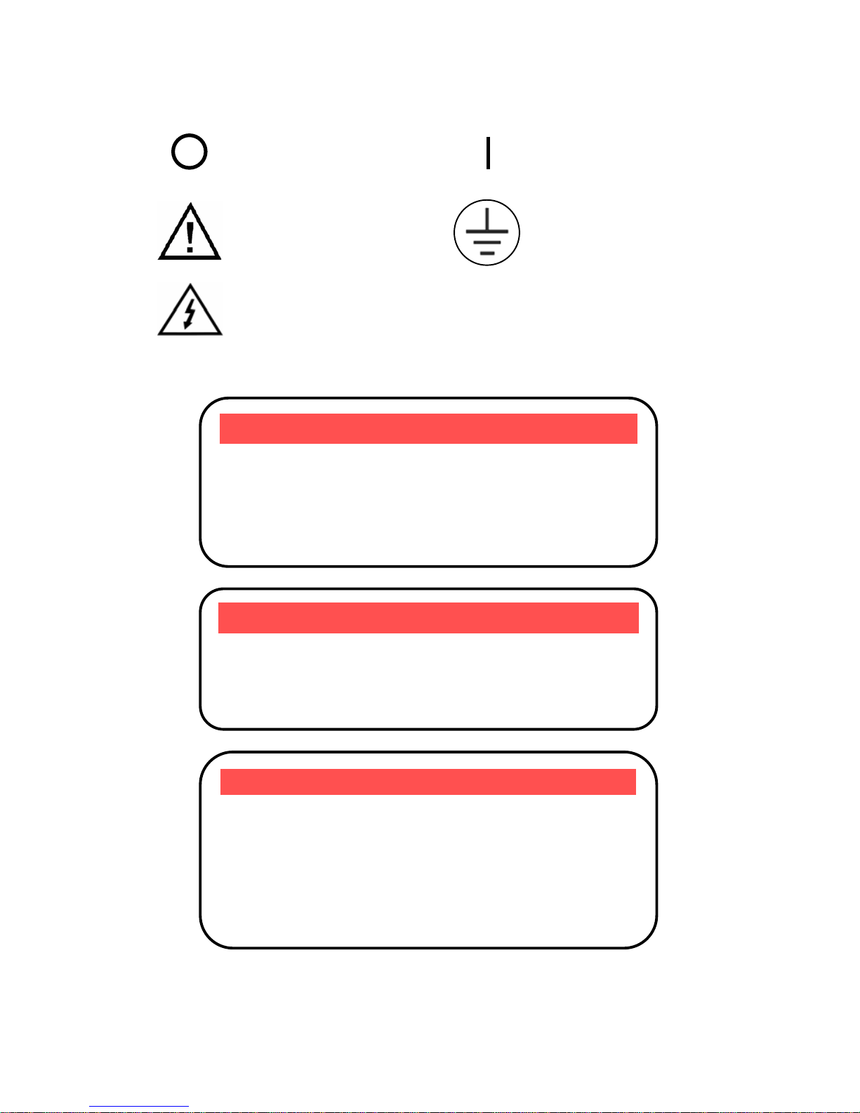
Symbols
Power Off Power On
Caution, refer to manual Earth ground
Caution, risk of electric shock
General Warnings
WARNING
To avoid electrical shock, ensure a 3-prong power cord
is used, and is plugged into a earth-grounded
receptacle. Failure to do so can result in severe injury or
death.
CAUTION
There are no user-serviceable parts inside. All service
and repair work shall be done by Arroyo Instruments or
personnel authorized by Arroyo Instruments.
Modifications done by non-authorized personnel will
void the warranty. Please see the Service section later in
this manual for instructions on how to obtain service for
this instrument.
WARNING
This instrument is intended for use by qualified
personnel who understand the shock and laser hazards
and are familiar with safety procedures required to avoid
injury. Read this manual completely before attempting to
use this product.
Page 5

5235 TECSource User’s Manual · Page 5
Quick Start
The TECSource was designed with ease of use in mind, and you will likely have
little need for this manual for almost all of the features the unit offers. This
section will show how you can quickly get the unit up and running in almost no
time.
The 5235 has a universal input power supply, accepting 90 to 240 VAC, and 50
or 60 Hz. This covers all conventional power worldwide, but ensure your AC
power meets these requirements.
Plug the AC cord into the unit and into the wall outlet. Turn on the power switch
located on the IPC, and the unit will power up, displaying the model information
and firmware version number.
Press the MENU button to enter the menu, and using the knob, turn to the right
until the I Lim setting is displayed. Press the knob to edit the setting, and adjust
the limit as appropriate to your Peltier. Press the knob again to save the value.
Make the same adjustments to the high and low temperature limits (T-High Lim
and T-Low Lim), as appropriate for your application.
The unit comes pre-programmed for the BetaTHERM 10K3A1 thermistor. If the
TECSource is being connected to a LaserMount, no changes need to be made,
as this is the thermistor used in the mount. However, if you are using
manufacturer’s thermistor or a different BetaTHERM thermistor, you will need to
verify the Steinhart-Hart coefficients are set correctly. Navigate to the Sensor
Coeffs sub-menu, pressing the knob to enter the sub-menu. Adjust the
constants to reflect the values for your thermistor.
Once you have made all your adjustments, press the MENU button to exit the
menu (in the future, if you’re only changing one value, you do not need to press
the knob – pressing the MENU button while changing a value will save the value
and exit).
Next, connect the cable between your LaserMount or other fixture and the
Output connector of the TECSource. We recommend using our cables as they
have been designed to work well with the TECSource. If using your own cables,
ensure they have been properly wired according to the pin-out of the
TECSource and your fixture.
Finally, set the set point to an appropriate temperature and press the Output
button. The output will turn on and you will see the voltage and current begin
driving the fixture to the set point you have chosen. Depending on the thermal
size of your fixture, it may take seconds or several minutes to reach the set
point.
Page 6

Page 6 · 5235 TECSource User’s Manual
If you notice the temperature is oscillating around the set point and not
stabilizing, you may need to adjust the Gain setting in the menu. If the
temperature is quickly jumping up and down, the Gain will typically need to be
reduced. If the temperature is slowly moving up and down, try a higher Gain.
You may need to experiment with several gain settings to find the ideal value,
and for even finer control, you can set the Gain to Custom and directly set the
PID control values.
It’s that simple. For more detailed operating and installation instructions, read
on.
Page 7
5235 TECSource User’s Manual · Page 7
Installation
Installation of the TECSource is very straightforward, as the quick start section
above illustrated. This section will provide additional details and considerations
for installing your TECSource.
After unpacking the unit, make sure all packing materials have been removed
and nothing obscures the ventilation ports on the back and bottom of the unit.
The 5235 has a universal input power supply, accepting 90 to 240 VAC, and 50
or 60 Hz. This covers all conventional power worldwide, but ensure your AC
power meets these requirements.
Powering Up the Unit
Once the correct voltage selection has been made, connect the AC power cord
to the unit.
Turn the power switch, located on the rear input power connector, into the on (|)
position. The unit will display the current firmware revision, go through a quick
power-up self-test, and return to the last known operating state.
Ventilation
The TECSource has vent holes on the rear and bottom of the unit. You must not
block these vent holes, or overheating may occur, causing damage to the unit.
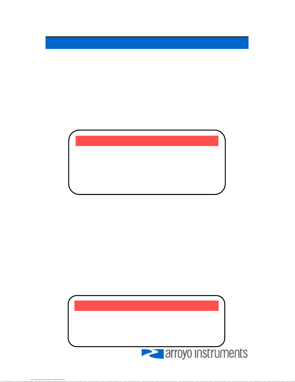
CAUTION
Do not exceed 250VAC on the line input.
It is critical to select the proper voltage selection prior to
applying power to the unit. If the actual voltage exceeds
the voltage selection by +/-10%, damage to the unit
may occur.
CAUTION
Do not operate the unit above +40°C ambient, and
ensure the instrument is properly ventilated, or the unit
may overheat and possible damage to the instrument
may occur.
Page 8

Page 8 · 5235 TECSource User’s Manual
Rack Mounting
A rack mount kit (p/n 1400-RM) for standard 19” racks is available for the
TECSource, and supports the rack mount of one or two units in a 2U (3.5”) high
opening. The rack mount kit provides sufficient clearance below the units for
ventilation, so units can be rack mounted immediately above other equipment
(no rack spacers required). Because the unit draws air from the bottom, and
therefore inside the rack housing, be sure that the internal rack ambient
temperature (which will typically be several degrees higher than room ambient)
does not exceed the unit’s operating temperature. If only racking one
instrument, you will also need a bay blank (p/n 1400-BL) to cover the second
opening in the rack mount kit.
Warm-up and Environmental Considerations
In order to achieve the highest level of accuracy, the TECSource should be
powered on for at least one hour prior to taking measurements. In addition,
ensure that the unit is not operating outside the ambient temperature range or
humidity conditions.
Page 9
5235 TECSource User’s Manual · Page 9
Front Panel Operation
Operation of the TECSource is very straightforward. The sections below will
help familiarize you with the front panel, the display, and the menu structure.
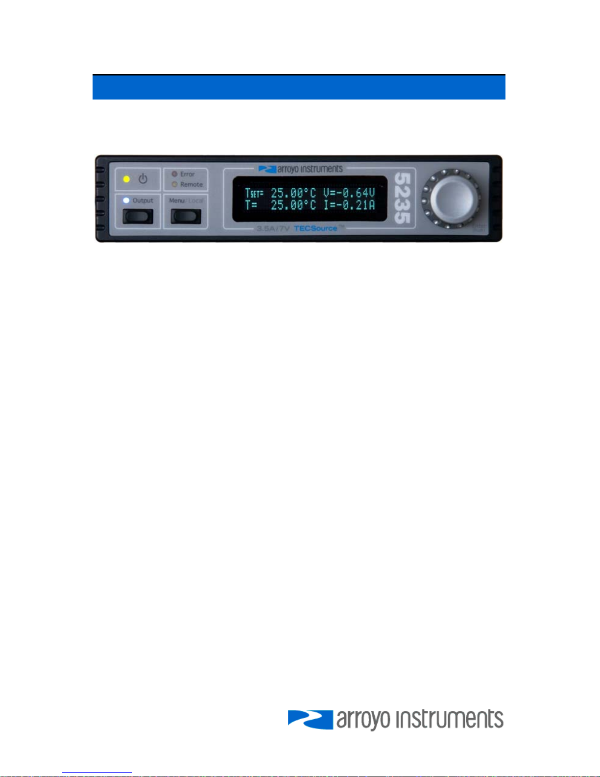
The front panel is designed for simplicity in operation. There are three buttons
on the front panel: Output, Menu, and the adjustment knob.
The Output button is used to turn the output on and off. Whenever the output is
on, the blue Output On LED will be lit.
The Menu button is used to enter the TECSource menu. When in remote mode,
it acts as a Local button, returning the instrument to local mode.
The large adjustment knob located on the right hand side of the unit is used to
change the set point or parameters in the menu. It also acts as a push button,
primarily as an enter button, when making changes in the menu. When in the
main screen, pressing the knob will change from Normal to Large display mode.
There are four LEDs: a green power LED that is lit whenever the AC power is
turned on; the blue Output On LED that indicates the TECSource is actively
controlling the temperature; a red Error LED that indicates an error has
occurred; and a yellow Remote LED that indicates the unit is being controlled via
a computer.
Whenever an error is generated, the red Error LED will light, and the error will be
displayed on the VFD display. There may be one or more errors, but only the
first error will be displayed. To display the next error, press Menu button. To
clear all errors, press the knob. A list of error codes can be found in the Error
Messages section below.
When the unit is in remote mode, the yellow Remote LED will be lit. More
information about how the instrument behaves in remote mode can be found in
the Remote Mode Operation section below.
Page 10
Page 10 · 5235 TECSource User’s Manual
Control Modes
The TECSource offers three control modes: constant temperature mode (T
Mode), and constant resistance mode (R Mode), and constant current mode (Ite
Mode).
Changing the control mode is done through the menu by changing the Mode
parameter to T Mode, R Mode, or Ite Mode.
Constant temperature mode uses the sensor constants to calculate the
resistance of the thermistor at the desired or actual temperature.
While most users will only need the temperature control mode, the constant
resistance mode allows you to bypass the sensor equation and directly select
the sensor set point. This can be useful when only the desired sensor value is
known, or when the sensor-to-temperature conversion values are not available
for your sensor.
Main Display Screen
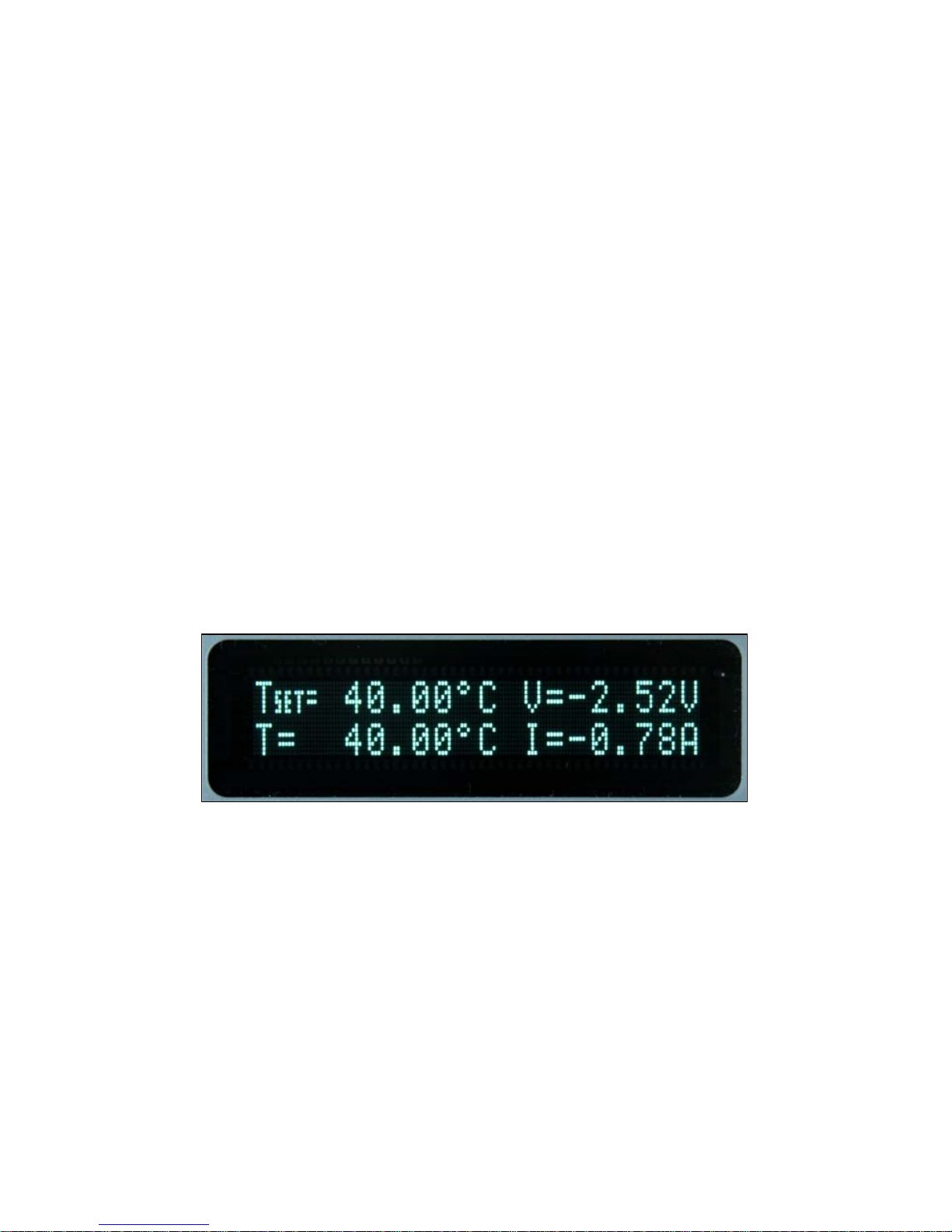
On the main display you will find the set point and two or three measurements,
depending on the configuration you have chosen. An example display is shown
below:
Sample Display
The set point will depend on the control mode you have selected. When in T
Mode, the set point will be temperature. When in R Mode, the set point will be in
ohms. When in Ite Mode, the set point will be in amps.
Measurements
The second line of the display contains the measurements appropriate for the
control mode. In T Mode, the actual temperature, current, and voltage can be
displayed, depending on the display mode. In R Mode, the actual sensor value
is displayed instead of the actual temperature. In Ite Mode, the actual
temperature is displayed.
No Set Point Error
Page 11

5235 TECSource User’s Manual · Page 11
Because 5235 TECSource uses a digital PID loop, it will always stabilize at the
set point, and you will never have a temperature offset, which is different that
most other temperature controllers.
Using Limits
The TECSource supports three different types of limits: temperature, sensor,
and current. There is both a temperature high and temperature low limit, and if
the actual temperature exceeds either of these limits, the output will be shut off.
Likewise, both high and low limits exist for the sensor (R limits), and the output
will be shut off if the sensor measurement exceeds either of these limits.
Page 12

Page 12 · 5235 TECSource User’s Manual
Settings and Menus
All parameters of the TECSource can be viewed and changed within the menu.
The menus are constructed with the most used parameters first. To change any
setting, press Menu to enter the menu then rotate the knob to select the
parameter to change. Press the knob to begin changing the value. As a visual
indication that you are in edit mode, you will see an asterisk appear next to the
value. Once you have made your change, press the knob or Menu button to
store the value. Pressing the Menu button will store and exit the menu, while
pressing the knob will store the value but leave you in the menu to make
additional changes.
Some settings are contained inside a sub menu, such as communications
settings. To access the sub menu, simply press the knob to enter the sub menu
when its name is displayed.
Below is a complete list of available settings:
Menu Description Factory
Default
Root Menu Main Menu
Mode This set the operating mode (T Mode, R
Mode, or Ite Mode) of the temperature
controller.
T Mode
Mount Specify the mount connected to the
TECSource. If using a LaserMount, select
the appropriate model. Otherwise, select
User Defined.
User
Defined
I Lim I Lim sets the current limit of the temperature
controller. The limit should be set to a value
that is suitable for your Peltier device.
3A
Gain Gain controls the response of the
temperature controller. A higher gain value
will cause the controller to respond more
quickly to the difference between the set
point and the actual temperature, while a
lower value will cause it to respond more
slowly. Select PID for direct access to the PID
parameters. Read more on setting gain
below.
30
PID P The proportional term of the PID loop. Will
only be available if Gain is set to PID.
1
Page 13
5235 TECSource User’s Manual · Page 13
Menu Description Factory
Default
PID I The integral term of the PID loop. Will only be
available if Gain is set to PID.
0.01
PID D The derivative term of the PID loop. Will only
be available if Gain is set to PID.
0
Sensor Sets the temperature measurement sensor.
Can be Therm 100uA or Therm 10uA.
Therm
100uA
T-Low Lim T-Low Lim is the lower temperature limit. If
operating in T Mode and the actual
temperature drops below this value, the
output will be turned off. Temperature limits
not monitored in R Mode or Ite Mode. Limit
monitoring can also be disabled in software
(see TEC:ENAB:OUTOFF command).
-99°C
T-High Lim T-High Lim is the upper temperature limit. If
operating in T Mode and the actual
temperature rises above this value, the
output will be turned off. Temperature limits
not monitored in R Mode or Ite Mode. Limit
monitoring can also be disabled in software
(see TEC:ENAB:OUTOFF command).
125°C
R-Low Lim R-Low Lim is the sensor low limit. If
operating in R Mode and the actual sensor
measurement drops below this value, the
output will be turned off. R limits are not
monitored in Ite Mode. Limit monitoring can
also be disabled in software (see
TEC:ENAB:OUTOFF command).
0.01kΩ
R-High Lim R-High Lim is the sensor high limit. If
operating in R Mode and the actual sensor
measurement exceeds this value, the output
will be turned off. R limits are not monitored
in Ite Mode. Limit monitoring can also be
disabled in software (see
TEC:ENAB:OUTOFF command).
45kΩ
Tol Time Tolerance time is the amount of time, in
seconds, that the actual temperature must be
within the set point temperature +/- the Tol
Temp value for the unit to be considered in
tolerance.
5 seconds
Page 14

Page 14 · 5235 TECSource User’s Manual
Menu Description Factory
Default
Tol Temp Tolerance temperature is a temperature band
(in °C) around the set point temperature.
When the actual temperature is within this
band for longer than the Tol Time setting,
then the unit is considered to be in tolerance.
0.1°C
H/C Mode This selects the heating and/or cooling mode
of the TECSource. See the section below
titled “Resistive Heaters and Heat/Cool Only
Modes” for more information.
Heat/Cool
Cable R The resistance of the cable and connectors,
in ohms. This setting allows for accurate
voltage measurement at the TEC by
removing the voltage loss of the cable.
0.0080Ω
Sensor Coeffs Sensor Coefficients Menu
ThermA The A term in the Steinhart-Hart equation.
1.12924E-03
ThermB The B term in the Steinhart-Hart equation.
2.34108E-04
ThermC The C term in the Steinhart-Hart equation.
0.87755E-07
Comm Menu Communications Menu
Baud This sets the baud rate for the RS232 serial
port. See the Computer Interfacing Manual
which is included on the CD that
accompanied this product.
9600
Err While
Rmt
To turn off the display of errors while in
remote mode, set this value to “No”. To
display errors while in remote mode, set this
value to “Yes”.
Yes
Terminal
Mode
Terminal mode simply echoes any characters
received over the serial or USB interfaces.
No
Msg Term This controls the output message
termination, and can be set to CR/LF, CR, LF,
or None.
CR/LF
Page 15
5235 TECSource User’s Manual · Page 15
Menu Description Factory
Default
Sys Menu System Settings Menu
Disp Mode Display mode, which is used to control the
layout on the main screen. Normal will
display four values, typically the set point
temperature, read back temperature, current,
and voltage. Large will display the read back
temperature, sensor, or current, depending
on the mode (T, R, or ITE mode,
respectively). When changing the set point,
the set point will be displayed during the set
point change.
Normal
Brightness The vacuum florescent display can be set to
one of eight brightness levels.
100%
Audible
Beep
This setting controls when the unit produces
audible feedback. Set to No to prevent
sound, or Yes or audible alerts such an error
messages.
Yes
Lockout
Knob
Lockout knob allows you to disable knob
operation from the main display. This
prevents accidental changes of the set point.
The knob will always work in the menus
regardless of this setting.
No
Knob Speed Controls the adjustment speed of the knob.
Possible values are slow, medium, and fast.
Slow
Page 16
Page 16 · 5235 TECSource User’s Manual
Rear Panel
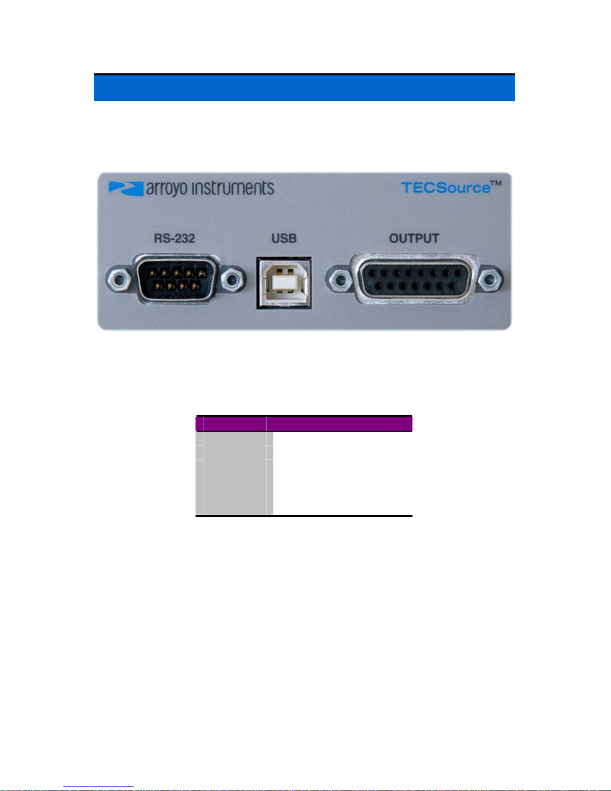
In addition to the input power connector described above, there are three
connectors on the rear panel of the TECSource: Output connector, USB
connector, and RS232 connector.
TECSource Rear Panel
TEC Output Connector
The Output connection is a female DB-15, and has the following pin-out:
DB-15 Pin Description
1, 2, & 9 TE (+)
3, 4, & 10 TE (-)
5 & 6 Earth Ground
7 Sensor+
8 Sensor11 thru 15 No connection
Output Connector (DB-15 Female)
USB Connector
The USB connector is a standard Type B female connector, and can be plugged
into any USB 1.1 or USB 2.0 port. For more information on using the USB
interface, see the Computer Interfacing Manual which is included on the CD
that accompanied this product.
RS232 Connector
The RS232 connection is male DB-9 connector wired in a NULL modem
configuration.
Page 17
5235 TECSource User’s Manual · Page 17
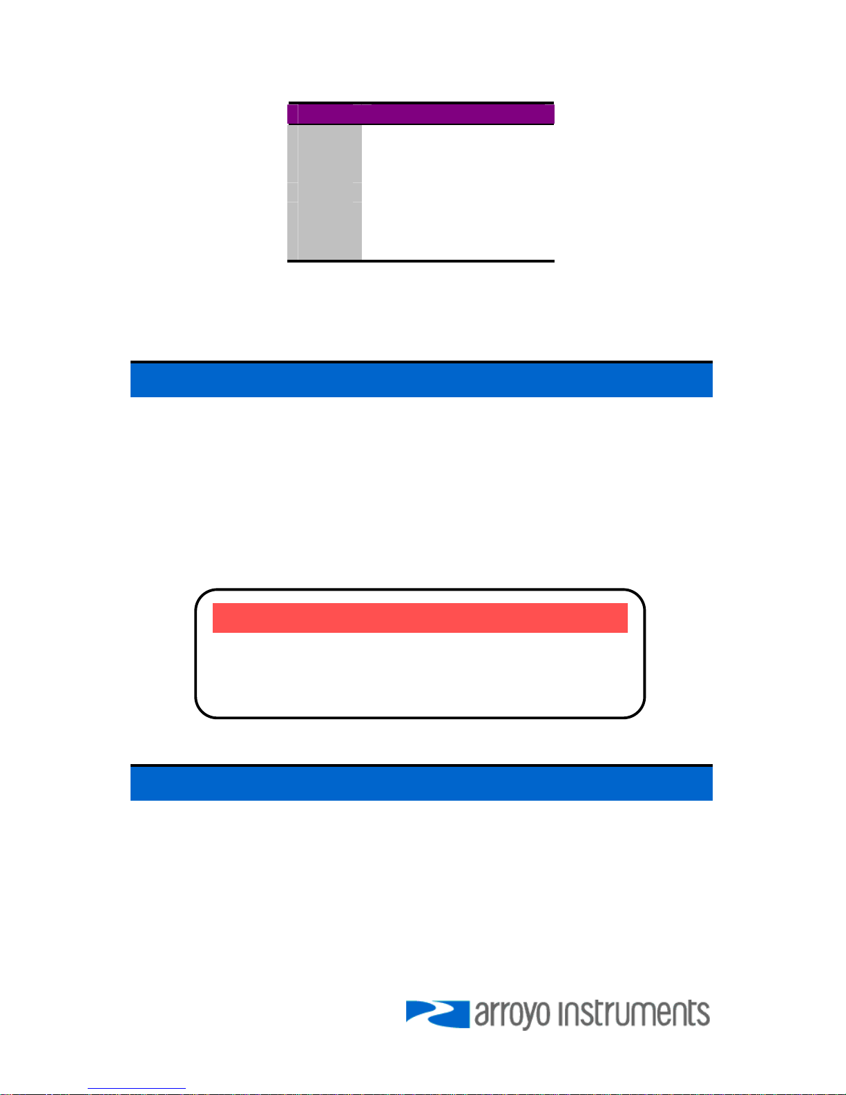
Pin Description
2 Receive
3 Transmit
5 Ground
1,4,6 Commoned together
7,8 Commoned together
9 No connection
Shell Earth ground
RS232 Connector (DB-9 Male)
For more information on using the RS232 interface, see the Computer
Interfacing Manual which is included on the CD that accompanied this product.
Connecting to the TECSource
Arroyo Instruments carries two cable assemblies specifically designed for
connecting the TECSource to temperature controlled fixtures or devices. Part
number 1260 is a two meter cable, designed for use with Arroyo Instruments
mounts, such as the 202 and 204 Butterfly LaserMounts, and has DB-15
connectors on both ends, one male and one female.
For custom applications, a two-meter cable with a male DB-15 on one end and
stripped and tinned leads on the other is available as part number 1261.
See the manual for your fixture for additional safety and operational information.
Selecting the Fixture
The TECSource has integrated support for many of the mounts offered by
Arroyo Instruments, such as the 204 TEC Butterfly LaserMount. To simplify
operation when using these mounts, you can change the Mount setting in the
menu to the mount type you are using. By selecting a mount, the current limit,
temperature limits, default gain, and sensor settings are automatically adjusted
to values appropriate to the mount, and menu settings limited to the capabilities
of the mount. For example, when the 204 is selected, the Sensor setting is
hidden from the menu, and the current limit is adjusted to the mount’s rated limit
to prevent damage to the mount’s Peltier cooler.
NOTE
Connections to the TECSource and the fixture must be
secure. Tighten any screws on the DB-15 connectors,
and make sure all connections are in good condition.
Page 18

Page 18 · 5235 TECSource User’s Manual
Adjusting the Mount setting to User Defined removes all software limits, allowing
unrestricted operation of the TECSource.
Remote Mode Operation
Remote mode operation is when the TECSource is being controlled by a
computer over the USB or RS232 interfaces. When in remote mode, the
TECSource behaves differently, preventing you from affecting the operation of
the instrument. Some of the primary differences are you will not be able to
change the set point, you cannot enter the menu, and the knob is disabled.
You can exit remote mode at any time by pressing the MENU button, which has
a secondary function to return the TECSource to local operation when in remote
mode.
While in remote mode, the Remote LED also acts as an activity indicator, and
will flash whenever there is communication with the computer.
Details on how to communicate with the TECSource can be found in a separate
Computer Interfacing Manual, which is included on the CD that accompanied
this product.
Installing the USB Drivers
Using the TECSource via USB is just as simple as using the serial port. In fact,
once you have installed the USB drivers, the instrument will appear as a virtual
serial port that you can use just like a normal serial port.
To install the drivers, simply plug in the instrument to your computer. When the
Add New Hardware wizard appears, insert the CD you received with the
TECSource and follow the on-screen instructions.
Once the drivers are installed, to determine the COM port number, go to Control
Panel and select System. Once the System Properties dialog appears, choose
the Hardware tab then click on the Device Manager button. When the Device
Manager appears, click on the plus sign to the left of Ports. The port identified
as an USB Serial Port is the TECSource. In the event you have multiple
TECSource instruments plugged in simultaneously, you will need to experiment
to see which instrument was assigned to which port. For example, you could
change the set point when the output was off to see which unit’s set point
changed.
Page 19
5235 TECSource User’s Manual · Page 19
Working With Thermistors
The TECSource is designed to work with negative temperature coefficient (NTC)
thermistors, such as the BetaTHERM 10K3A1 thermistor used in the
LaserMounts. A thermistor works by translating temperature into resistance,
with resistance decreasing as temperature increases (hence the ‘negative
coefficient’).
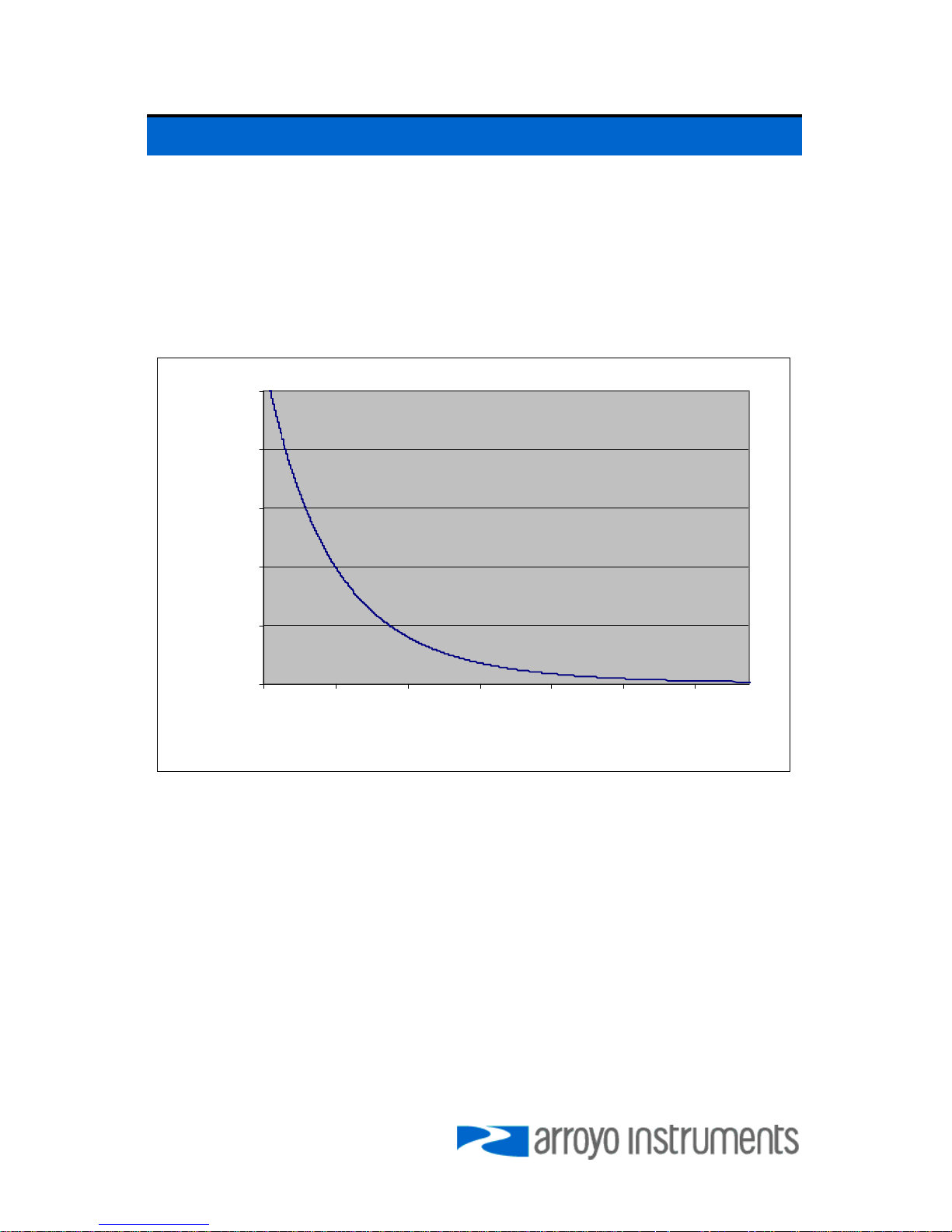
Here is a typical response curve of a thermistor:
0
10000
20000
30000
40000
50000
-10.00 10.00 30.00 50.00 70.00 90.00 110.00
Tem perature (°C)
Resistance (Ω)
Typical Resistance vs. Temperature Graph
As can be seen be the graph, the resistance of the thermistor drops very quickly.
In the typical control range (0°C to 40°C), typical 10K thermistors offer good
sensitivity to changes in temperature, and this is the range in which most 10K
thermistors are typically used. 10K thermistors can be used at much higher
temperatures, but will suffer poorer temperature stability performance because
of the lower sensitivity. When evaluating the performance of a thermistor, it is
important to understand the resistance sensitivity of the thermistor at your
application temperature, which varies greatly by temperature and thermistor
types.
The TECSource supports operation using a 10μA or 100μA constant current
source, which limits the upper control range to 450kΩ and 45kΩ, respectively.
To minimize noise and maximize stability, you should select highest current
while still allowing you full operation across your required temperature range.
Page 20

Page 20 · 5235 TECSource User’s Manual
The typical setting is 100μA, but your application will determine the actual
needs.
The Steinhart-Hart Equation
As can be seen from the temperature versus resistance graph above, resistance
varies inversely with temperature in a non-linear fashion. This relationship can be
accurately modeled by polynomial equations, and one such being the SteinhartHart equation:
3
)ln(*)ln(*
1
RCRBA
T
++=
The coefficients A, B, and C can usually be obtained from the thermistor
manufacturer. The TECSource defaults to the coefficients for the BetaTHERM
10K3A1 thermistor (A = 1.12924x10
-3
, B = 2.34108x10⁻⁴, C = 0.87755x10⁻⁷). You
can change the coefficients under the Sensor Coeffs menu.
Resistive Heaters and Heat/Cool Only Modes
The TECSource supports temperature control using resistive heaters instead of
Peltier coolers. With resistive heaters, cooling is obviously not possible, and the
TECSource must be configured to not attempt to cool the output, or a run-away
condition will occur when the cooling current actually causes additional heating.
If your application requires, you can also configure the TECSource to operate in
a cool-only mode. This is only possible with Peltier coolers.
To change the cooling mode, adjust the H/C Mode setting to Heat/Cool, Heat
Only, or Cool Only, as appropriate.
Gain Control and the PID Loop
The TECSource supports a fully configurable PID loop, allowing full
customization of the PID control parameters. To simplify control, eight standard
gain settings are also defined, and many applications can achieve acceptable
performance with these predefined gain settings, eliminating the need to
understand and adjust the PID loop.
The predefined gains are numbered 1 through 300, and set using the Gain
menu setting. Increasing the gain value will increase the speed of the control
loop. For full access to the PID parameters, change the Gain setting to PID, and
the individual P, I, and D values will be available as settings in the menu.
Page 21

5235 TECSource User’s Manual · Page 21
To manually adjust the PID, start by changing the I and D values to zero, and
adjust the P value so that it reaches the set point as quickly as possible without
overshooting the set point an unacceptable amount. Gradually increase the I
value until the set point is achieved without oscillation. In many systems, the D
term is not needed and may be left at zero.
For additional information on PID loop tuning, consult online resources such as
Wikipedia (http://en.wikipedia.org/wiki/PID_controller) or search for terms such
as “Ziegler-Nichols method”, or “PID Loop”.
Compensating for Cable Resistance
Because the high currents the TECSource can drive through the Peltier, the
voltage loss through the cable and connectors of the system can significantly
affect the TEC voltage measurement. In most cases, accurate voltage
measurements are not needed, and the default compensation of the instrument
is sufficient. To improve the compensation, the Cable R setting in the menu
allows you to specify the cable resistance, which is then used to dynamically
subtract the voltage drop by simply using the formula V = IR to calculate the
voltage loss, where I is the TEC ITE current, and R is the Cable R setting. This
value is then removed from the voltage measurement to display an accurate
TEC voltage measurement.
The safest method of calculating cable resistance is to short the ITE+ and ITE–
connections, making sure whatever you are using to short the terminals is not
itself adding resistance to the circuit. Use short, heavy gauge wires, preferably
soldered onto the terminals to minimize any resistance the short might add.
Place the short as close to the Peltier as is reasonable. A simple approach is to
unplug the cable from the mount and place a shorting plug on the mount end of
the cable, which is easily made from a male DB15 connector and a soldering
iron to solder the ITE+ and ITE– pins together. Make sure the Peltier is
disconnected to protect it from current overloading during the test.
Change the instrument to ITE mode and set the current to 5A. Depending on
your setup, you may first need to change the Mount to User Defined and adjust
the limit to 5A. Turn on the output and after the voltage has stabilize, make a
note of it and turn the output off. Enter the measured voltage into the following
equation to calculate Cable R:
Cable R = Voltage / 5
Enter the resulting values into the Cable R menu entry and return the instrument
to its original configuration. Typical values for Cable R are 0.008 to 0.040, but
depend on your actual configuration.
Page 22

Page 22 · 5235 TECSource User’s Manual
Specifications
All values relate to a one-hour warm-up period.
Description
Drive Channel
Current
Range (A) 3.5
Compliance Voltage (V) > 7
Max Power (W) 24
Resolution (A) 0.01
Accuracy (+/- [% set point + mA]) 0 + 30
Noise/Ripple (mA, rms) < 3
Temperature Control
Range (ºC)1 -99 to 250
Resolution (ºC) 0.01
Thermistor Accuracy (± ºC)2 0.053
Short Term Stability (1hr) (± ºC)4 0.004
Short Term Stability (24hr) (± ºC)4
0.01
Measurement Channels
Current
Resolution (mA) 10
Accuracy (+/- [% reading + mA]) 0 + 30
Voltage
Resolution (mV) 10
Accuracy (+/- [% reading + mV]) 0 + 50
Sensor
10μA Thermistor
Range (kΩ) 0.1 - 450
Resolution (Ω) 10
Accuracy (+/- [% reading + Ω]) 0.05 + 50
100μA Thermistor
Range (kΩ) 0.05 - 45
Resolution (Ω) 1
Accuracy (+/- [% reading + Ω]) 0.05 + 5
Current Limit
Resolution (mA) 10
Accuracy (+/- mA) 50
Other
TEC Connector Female DB-15
Display Type 2x20 VFD
Computer Interface USB 2.0 Full Speed
RS-232 (DB-9, male)
Power 90 – 240 V, 50/60 Hz
Size (H x W x D) [inches (mm)] 3.5 (90) x 8.5 (215) x 11 (280)
Operating Temperature +10°C to +40°C
Storage Temperature -20°C to +60°C
1
Software limits. Actual range dependent on sensor type and system dynamics
2
Accuracy figures are the additional error the 5235 adds to the measurement, and does not include the
sensor uncertainties.
3
25°C, 100μA thermistor
4
Stability measurements done at 25°C using a 10kΩ thermistor on the 100μA setting. The number is ½
the peak-to-peak deviation from the average over the measurement period.
Page 23

5235 TECSource User’s Manual · Page 23
Error Messages
Error
Code
Description Cause
E-100 General Error The error code is non-specific, and is
generally used when no other error code is
suitable.
E-102 Message too long The message is too long to process
(USB/Serial only).
E-104 Type not allowed The RADix type was invalid
E-123 Path not found The message used an invalid path
command (USB/Serial only).
E-124 Data mismatch The message contained data that did not
match the expected format (USB/Serial
only).
E-126 Too few or too many
elements
The command requires more or less than
the number of parameters actually supplied.
E-127 Change not allowed An attempt was made to change a
parameter that cannot be changed, or is
currently read-only.
E-201 Data out of range The message attempted to set a value that
was outside the allowable range (USB/Serial
only).
E-202 Invalid data type When trying to parse the message, the data
was in an invalid format (USB/Serial only).
E-204 Suffix not valid An invalid number base suffix (radix) was
encountered when parsing a number
(USB/Serial only).
E-402 Sensor open, output
turned off
A sensor open circuit was detected and the
output was turned off.
E-403 Module open, output
turned off
A Peltier module open circuit was detected
and the output was turned off.
E-404 I limit, output turned
off
A current limit was detected and the output
was turned off.
E-405 V limit, output turned
off
A voltage limit was detected and the output
was turned off.
E-406 Thermistor resistance
limit, output turned off
The thermistor resistance limit (high or low)
was exceeded and the output was turned
off.
E-407 Temperature limit,
output turned off
The temperature limit (high or low) was
exceeded and the output was turned off.
E-409 Sensor changed,
output turned off
The sensor type was changed, causing the
output to be turned off.
Page 24

Page 24 · 5235 TECSource User’s Manual
Error
Code
Description Cause
E-410 Temperature was out
of tolerance, output
turned off
The temperature went out of tolerance and
the output was turned off.
E-415 Sensor short, output
turned off
A sensor short circuit was detected and the
output was turned off.
E-416 Cal failed An error occurred during calibration that
caused the calibration to fail. The unit is no
longer in calibration mode.
E-419 TEC not stable The TEC is considered stable if the
temperature has changed less than 0.02°C
for more than 20 seconds.
E-433 Not a TEC The TEC:CHAN command attempted to
select a non-TEC channel
E-434 Ite limit exceeds
cable rating
The cable plugged into the unit is not rated
to carry the current as set by the current
limit. Use a 1262 cable, 1262 cable, or
custom cable with ID pin connected to
analog ground, or reduce the current limit
below 5A.
E-435 Mode Change A mode change occurred when the output
was on, forcing the output off.
E-997 Control error, cycle
power
A hardware control error occurred, cycle
power to resolve. If error continues to occur,
contact factory.
E-998 Command not
supported
A command was received that is not
supported by this instrument.
E-999 Non-specific error A non-specific error was encountered.
Page 25

5235 TECSource User’s Manual · Page 25
Maintenance and Service, and Calibration
Maintenance
The TECSource requires no regular maintenance other than product calibration.
To clean the instrument, use cotton cloth that is only damp (not wet) with a light
solution of soap and water.
Fuses
Under normal operation, you should never need to replace a fuse. However, if
either fuse does blow, use only T 250V, 1.0A, IEC 60127-2 5x20mm metric fuses
as replacements.
If, after replacing the fuse, it continues to blow, immediately discontinue use of
the instrument and contact service for support.
Service
Service and repair for the TECSource can be obtained by contacting the
distributor from where you purchased the instrument, or directly from Arroyo
Instruments. A complete list of distributors is available on the Arroyo web site.
You can contact Arroyo Instruments through one of these methods:
By mail: Arroyo Instruments
373 Front Street, Suite B
Grover Beach, CA 93433
USA
By phone: +1 (805) 481-6684
By fax: +1 (805) 481-6628
By email: [email protected]
On the web: http://www.arroyoinstruments.com
In all cases, Arroyo Instruments requires a return materials authorization (RMA)
number. You must contact Arroyo Instruments and obtain an RMA number prior
to returning your instrument, or the shipment may be rejected and sent back to
you.
Page 26

Page 26 · 5235 TECSource User’s Manual
Notes:
Page 27

5235 TECSource User’s Manual · Page 27
Notes:
Page 28
Page 28 · 5235 TECSource User’s Manual
Copyright © 2008, Arroyo Instruments. All Rights Reserved.
P/N 530-1012 Rev
A
 Loading...