

Tecson Tank-Spion Digital LX-NET, Tank-Spion Digital LX-GSM, Tank-Spion Quadro LX-Q-GSM, Tank-Spion Quadro LX-Q-NET Installation Instructions Manual
Installation Instructions
GENERAL
2
Electronic tank monitoring devices with data messaging
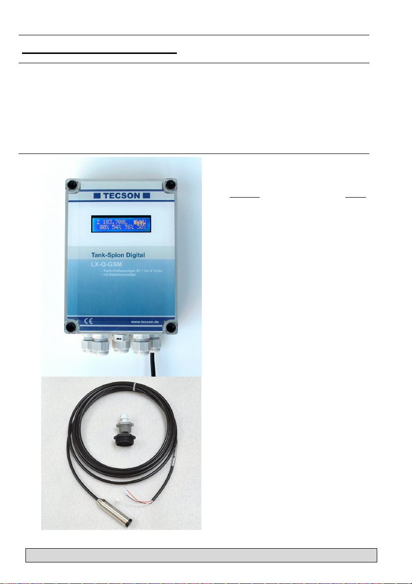
Tank-Spion Digital LX-NET
Tank-Spion Digital LX-GSM
Tank-Spion Quadro LX-Q-NET
Tank-Spion Quadro LX-Q-GSM
and
Techn. Documentation
Content:
MOUNTING INSTRUCTIONS 3
MOUNTING OF LEVEL PROBE 3
ELECTRIC INSTALLATION 4
CONNECTION CLAMPS 5
DEVICE MESSAGES (SMS) 6
DEVICE PARAMETERS (SMS) 6
INITIAL SETUP 8
FUNCTION CHECK 9
MAINTANCE 9
NETWORK CONNECTION 10
BROWSER ACCESS 11
ERROR CODES 13
TECHNICAL DATA 15
LIQUIDS 15
ACCESSORIES 16
LABELING 16
Page:
01-2016
LX-(Q)-GSM / LX-(Q)-NET Techn. Docum. + Installation P. 1

GENERAL
The electronical tank content display device of LX-Serie is to be used for monitoring of tank levels
in pressureless liquid tanks.
This documentation is to be used for the devices LX-GSM, LX-Q-GSM and LX-NET, LX-Q-NET.
Beside the liter monitoring several other functions are available, in most cases with an extra
module or adaptor. These functions are temperature measuring, data transmission or bindung to
facility management systems.
The devices LX-GSM and LX-NET provide an output relay. It operates automatically depending
on the tank filling level. Besides it can be operated by remote control (telecontrol). The relay is
able to control an alert unit, to switch a magnetic valve or to protect a pump from running dry. The
relay has opening and closing contacts for switching two separate current circuits.
Level probe:
Die Geräte-Sets LX-GSM und LX-NET werden jeweils mit 1 Tankmesssonde geliefert.
The LX-GSM and LX-NET sets are provided with 1 level probe each.
The LX-Q-GSM and LX-Q-NET types offer 4 measuring inputs for up to 4 level probes. They
monitor the individual content of each tank and total stock.
The level probe can be mounted by standard with a 1“ or 1½“ screw thread. For mounting in plastic tanks a grommet and a PG-screwing is provided.
Electric supply: 230V AC.
A special type of the monitoring device for DC 24V or DC 12V can be delivered.
The monitoring device has a LCD display by 2 x 16 characters.
The indicated values are not calibrated for billing purposes.
For the intended operation and to adhere the warranty the following instructions for mounting and
use are to be followed and to be handed over to the user.
Device types:
The Q (quadro) device types provide 4 measuring inputs but no output relay.
The other device types provide only 1 measuring input and one output relay.
LX-GSM + LX-NET:
These sets are usually delivered with one standard measuring probe.
LX-Q-GSM + LX-Q-NET:
These ’Quadro’ sets are presented usually without measuring probes.
LX-GSM + LX-Q-GSM:
Additionally to liter monitoring these device types report the status by SMS.
They need a SIM card for mobile network. Prepaid is recommended.
The SIM card is not included.
The recipient can either be a mobile phone or the www.oilview.de system.
LX-NET + LX-Q-NET:
These device types have a LAN jack (RJ45) for direct Ethernet connection.
Your browser gets a HTML data page from the device. For calling the
data page from Internet the router port must be forwarded.
Data binding to www.oilview.de web server is available too.
P. 2 LX-(Q)-GSM / LX-(Q)-NET Techn. Docum. + Installation
01-2016

MOUNTING INSTRUCTIONS
•
Only qualified persons are allowed to install the measuring probe and to connect the display device. Follow the regulation for each liquid, especially for the risk of water pollution and for flammable liquids.
Condition for proper operation of measuring device is a professional installation. Follow the technical rules for planning, construction and operation of the entire facility.
Additionally follow the rules of preventions of accidents by the government safety organizations
and the instructions of mounting and operation of the storage tanks too.
• Condition for proper operation is a pressureless storage tank. The tank must have proper
ventilation. Oil tanks and gasoline tanks must be equipped with a level limiter.
• The cable entry in the tank has to be made watertight and vapor tight appropriately.
• The measuring probe and display device are not securety devices. They do not replace the
level limiter of a tank.
• Installation of the display device in explosive zones is not permitted.
Ask for an EEx-probe with Zener barrier. The tank level probe must be mounted inside the
tank with a cable protection pipe.
• 230V AC: The display device is connected to the power supply. Operating is only permitted
with closed box lid.
• Type 230V AC :
The display device is connected to the power supply system and may normally only to be
used with box cover closed.
• Type 12V / 24V DC:
As a special model this device type is supplied by a low voltage power supply of 24 V
(DC 20V-28V) or 12V (DC 11V-15V).
In case of inappropriate installation you lose any warranty.
MOUNTING OF LEVEL PROBE
In case of cellar steal tanks or subgrounded tanks use the included screw-
ing joint for mounting the measuring probe.
• If an old fuel gauge was used dismount it and use the tank screwing port.
• Subgrounded tanks normally provide an idle screwing port. Dismount the
dummy screwing.
• If there is no other appropriate opportunity the measure probe can be
installed in the bearing pipe. We recommend the use of a 1“ T pipe collar
with a 1“ nipple for the head of the bearing pipe.
The cable of the measuring probe comes out of the T pipe collar on the
side. Occasional bearing for control parallel to the cable of the measuring
probe is still possible.
Mounting:
• Switch off the oil burner and lock the suction pipe if necessary.
• Clear the screwing port of the tank.
• Put the cable of the probe through the screwing joint. Put the measuring
probe into the tank.
• Mount the screwing joint with PTFE sealing tape.
• Sink the measuring probe down to the ground of the tank. Fix the cable
with the PG screwing. The measuring probe may optionally lay or stand on
the ground of the tank.
• Zero-point calibration is normally not required..
• If necessary unlock the suction pipe, switch on the oil burner and check
the functions.
01-2016
LX-(Q)-GSM / LX-(Q)-NET Techn. Docum. + Installation P. 3
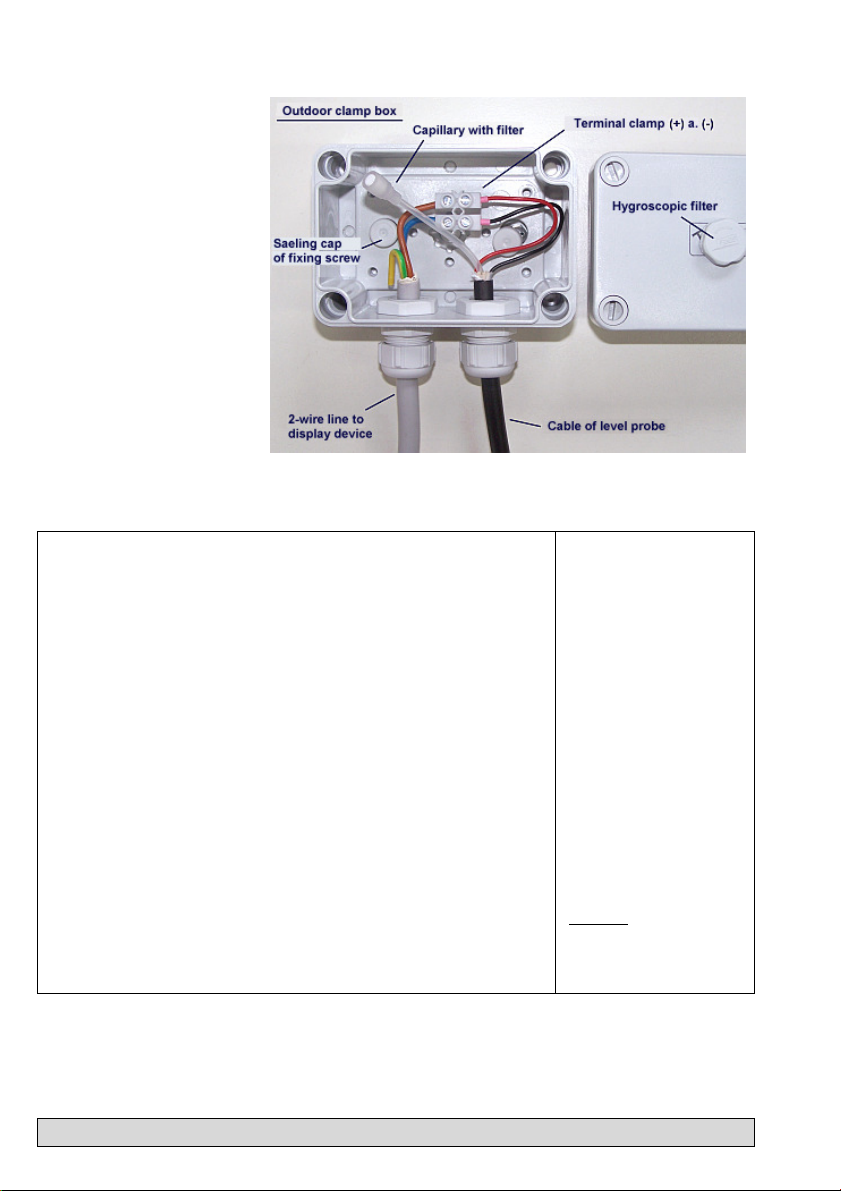
Probe box :
To be used
- outdoors
- in manhole pit (buried tanks)
- in damp locations.
The probe box must be watertight and ventilated
(for pressure balance of the
hydrostatic level probe).
ELECTRIC INSTALLATION
Interconnection of measuring probe to display device
Probe supply: Low-voltage DC
Connection: Connect the 2-wire probe cable as follows:
Air capillary: The air capillary must have ventilation to atmosphere.
Extension: The cable of the probe can be extended up to 100 m,
Shielding: Near to power lines it is recommended to use a
Supply voltage:
Voltage: AC 230 V, 50 Hz
Clamps: PE (protective conductor), N (neutral conductor),
Red(+) => clamp 1 , Black (-) => clamp 2.
The end of the probe’s cable and the air capillary
must be protected against humidity.
e.g. with NYM or YR (damp location) or NYY (soil).
Line diameter at least 2 x 0.4 mm².
In case of cable extension in a manhole pit or outdoors it is recommended to use a waterproof clamp
box with special air pressure ventilation (accessories).
shielded probe signal line. (Cable shielding has to be
grounded.)
L (phase).
Cable is not included in scope of delivery.
Refer to the figure on the
following page.
The capillary in the
probe’s cable must
have ventilation.
The capillary filter stays
attached!
Refer to probe instructions.
Caution:
Do never connect device type DC 24V or
12V to 230V.
P. 4 LX-(Q)-GSM / LX-(Q)-NET Techn. Docum. + Installation
01-2016
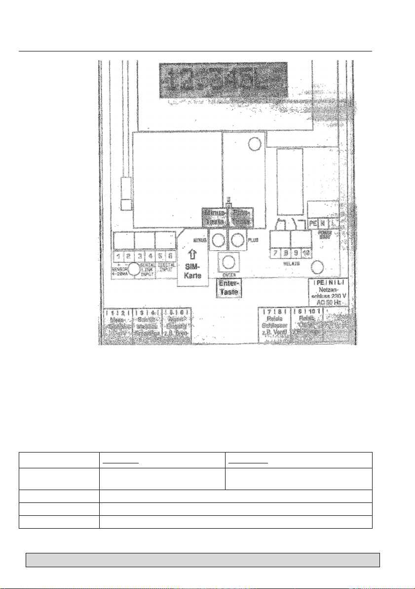
CONNECTION CLAMPS
Schaltspannung
Voltage
Steuerfunktion
If LX-GSM
and LX-NET
Relay connection:
The LX-GSM and LX-NET devices do have a double output relay. By this relay two separate electric circuits can be switched simultaneously, e.g. a signalling device on/off and an electric
valve off/on too.
Under initial conditions the relay contacts 7-8 are closed and relay contacts 9-10 are opened.
In case of event the relay operates so both contact pairs switch over. Then contacts 7-8 do open
and 9-10 do close.
At power outage or when the device goes out of order then the relay is under initial condition. in
Inital state Event state
Relay output
Contact 7 - 8 links
Contact 9 - 10 opened
Max. 250 V AC
Max. 3,5 A
For setup see menu item “6. Relay“ and GSM command #S (at LX-GSM)
Contact 7 - 8 opened
Contact 9 - 10 links
01-2016
LX-(Q)-GSM / LX-(Q)-NET Techn. Docum. + Installation P. 5
 Loading...