

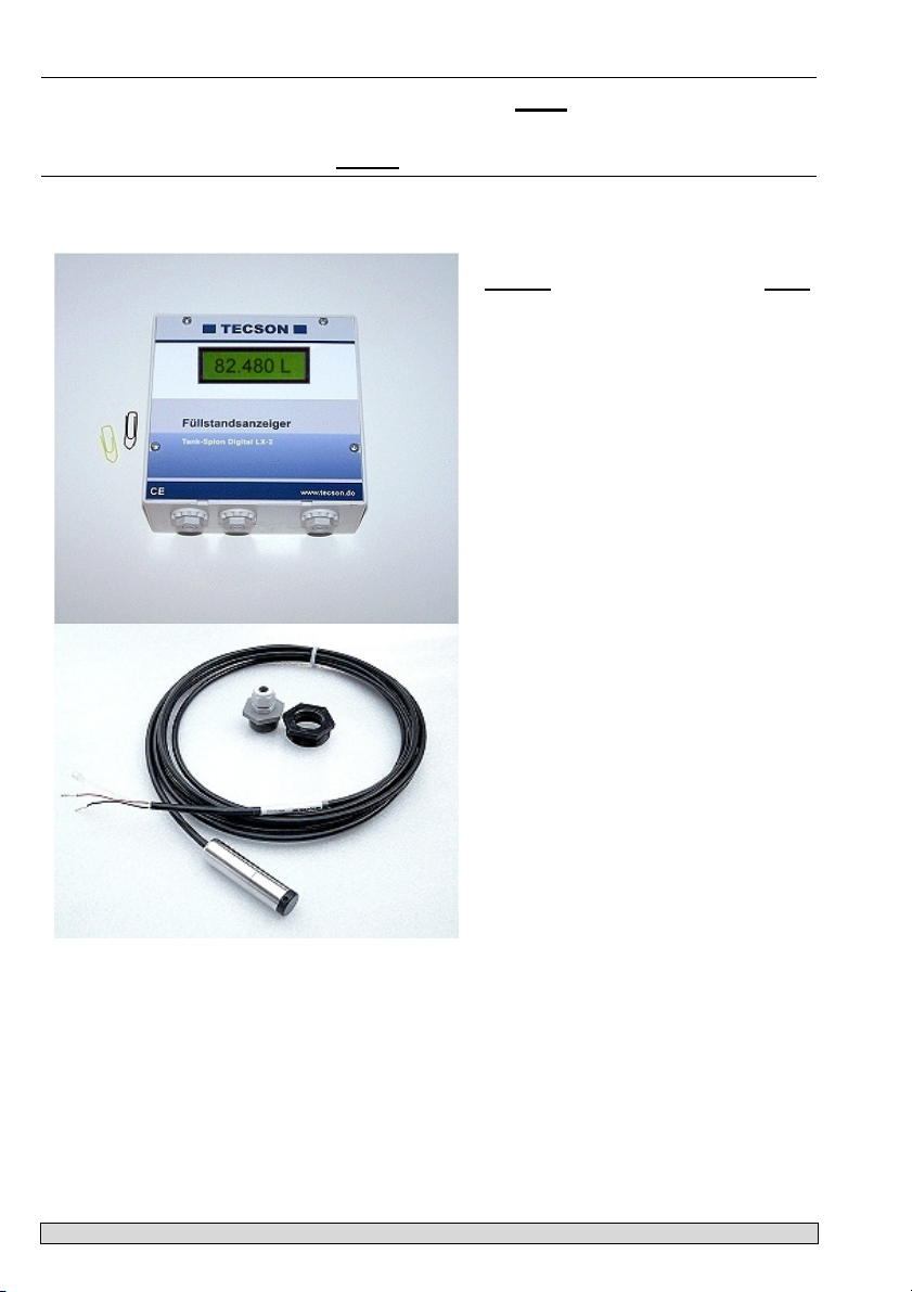
Tank-Spion Digital LX-2
Measuring an monitoring device for tank contents.
Type option: LX-2-R - with 2 relays aditionally.
Mounting and Instructions
Content:
IN GENERAL 1
STRUCTURE 2
LIQUIDS 2
LABELING 2
MOUNTING INSTRUCTIONS 2
MOUNTING OF MEASURING PROBE 3
ELECTRIC INSTALLATION 3
AUTOM. CHANGEOVER OF TANKS 4
INITIAL SETUP 5
SETUP MENU, COMPL. 7
ERROR CODES 10
FUNCTION CHECK 11
TECHNICAL DATA 11
ACCESSORIES 11
CONNECTION PLAN 12
Page:
IN GENERAL
The tank content display device LX-2 or LX-2-R is to be used for monitoring of tank levels in
pressureless liquid tanks. Aditional functions to liter displaying are e.g. temperature measuring,
data transmission or linking to facility management systems.
The LX-2-R type additionally provides two output relays, e.g. for controlling an alert unit, for
switching magnetic valve or dry protection of pump.
The displayed liter values are not to be used for billing purpose.
For the intended use and to abide the rules for warranty do strictly follow the Mounting and
Instructions, which have to be handed out to the owner.
P. 1 LX-2 / LX-2-R Mounting and Instructions
Version: 07-2009
STRUCTURE
The LX-2 (-R) has an eight characters LCD display and a measuring input for a level probe.
The LX-2-R type additionally provides 2 programable relays, with opening and closing contacts.
The measuring probe can be mounted with a screw joint of R1 “ or R1½ “.
A reduction for 2“ is not included in scope of delivery.
LIQUIDS
Liquid Liquid
Heating oil
Diesel oil
Bio Diesel oil
Plant oil
Petroleum
Carbamide dissolution
DIN EN 51603-1
DIN EN 590
DIN EN 14214
* after consulting
Flash point > 55°C
e.g. AdBlue
LABELING
Confirming to EN 50081-1 , EN 50082-1 and EN 61010-1 / A2
MOUNTING INSTRUCTIONS
Only qualifyed persons are allowed to install the measuring probe and to connect the display
device. Follow the regulation for each liquid, especially for the risk of water pollution and for
flammable liquids.
Condition for proper operation of measuring device is a professional installation. Follow the
technical rules for planning, construction and operation of the entire facility. Additionally follow the
rules for tank mounting and operation.
• Condition for proper operation is a pressureless storage tank. The tank must have proper
ventilation. Oil tanks and gasoline tanks must be equipped with a level limiter.
• The cable entry in the tank has to be made watertight and vapor tight by using PTFE sealing
tape.
• The measuring probe and display device are not safety devices. They do not replace the level
limiter of a tank.
• Installation of the display device in explosive zones is not permitted.
In that case ask for an EEx-probe with Zener barrier. The tank probe must be mounted inside
the tank with a cable protection pipe.
• The display device is connected to 230V AC. Operating is only permitted with closed box lid.
In case of inappropriate installation you lose any warranty.
Motor oil
Hydraulic oil
Glycerin
Glycol
Water
Gasoline with
flash point < 55°C
No used oil !
Only with EEx-probe
and Zener barrier
P. 2 LX-2 / LX-2-R Mounting and Instructions
Version: 07-2009
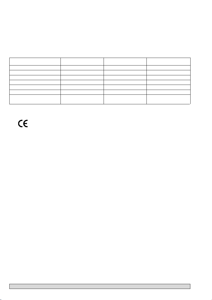
MOUNTING OF MEASURING PROBE
• In case of cellar steal tanks or subgrounded tanks use the included
screwing joint for mounting the measuring probe.
• If an old fuel gauge was used dismount it and use the tank screwing port.
• Subgrounded tanks normally provide an idle screwing port. In that case
dismount the dummy plug.
Mounting:
• In case of a heating oil tank switch off the oil burner and lock the suction
pipe if necessary.
• Clear the tank’s screwing port.
• Put the cable of the probe through the screwing joint. Put the measuring
probe into the tank.
• Mount the screwing joint with PTFE sealing tape.
• Sink the measuring probe down to the ground of the tank. Fix the cable
with the PG screwing. The measuring probe may optionally lay or stand on
the ground of the tank.
• Zero-point calibration is not required in normal case.
• If nessecary unlock the suction pipe, switch on the oil burner and check
the functions.
ELECTRIC INSTALLATION
Interconnection of measuring probe to display device
Probe supply: DC 15 – 24 V
Connection: Connect the 2-wire probe cable in the way:
Red(+) => clamp 1 , Black (-) => clamp 2.
Air capillary: The air capillary must have ventilation to atmosphere.
The end of the probe’s cable and the air capillary must
be protected against humidity.
Extension: The cable of the probe can be extended up to 100 m,
e.g. with NYM or YR or NYY.
Line diameter at least 2 x 0,4 mm².
In case of cable extension in a manhole or outdoors
it is recommended to use a waterproof clamp box with
special air pressure ventilation (accessories).
Shielding: Near by power current cables it is recommended to use
a shielded probe signal line. (Cable shielding has to be
grounded.)
Supply voltage:
Voltage: AC 230 V 50 Hz
Clamps: PE (protective conductor), N (neutral conductor),
L (phase).
Power line is not included in accessories.
P. 3 LX-2 / LX-2-R Mounting and Instructions
Refer to last page.
The capillary in the
probe’s cable must
have ventilation.
The capillary filter
stays attached !
Refer to probe
instructions.
Version: 07-2009
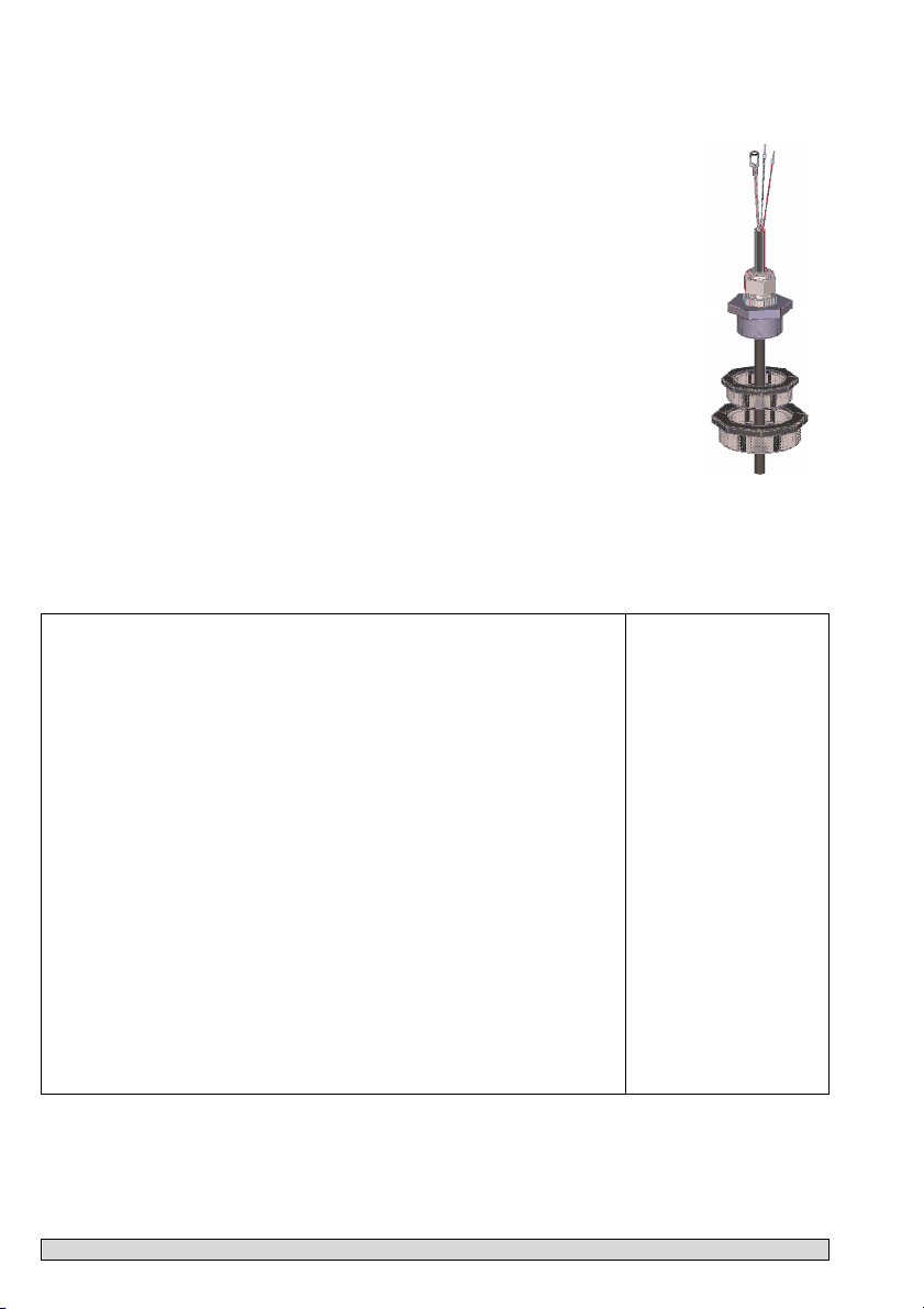
LX-2-R :
Relay connection
The LX-2-R type has two relays for controlling
external electric circuits or for alert signaling.
In case of failure or minimum level (or temperature
limit) the relay outputs 6-7 and 9-10 are linked and
the relay outputs 5-6 and 8-9 are opened; refer to
PCB print.
Normal state / Event state Normal state / Event state
Relay 1 Clamp 5 - 6 opened / Contact links Clamp 6 – 7 linked / Contact opens
Relay 2 Clamp 8 - 9 opened / Contact links Clamp 9 -10 linked / Contact opens
Voltage Max. 250 V AC
Current Max. 3,5 A
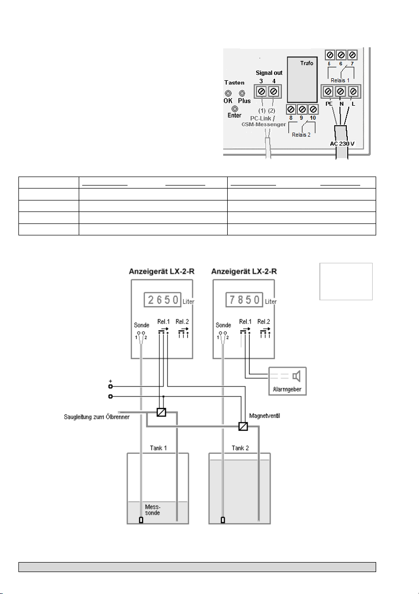
AUTOM. CHANGEOVER OF TANKS
Example
LX-2-R
P. 4 LX-2 / LX-2-R Mounting and Instructions
Version: 07-2009

INITIAL SETUP
Determine the tank data and enter them into the mode:
You find the push buttons (blue) on the PCB positioned between the connection clamps.
Press ENTER => Device enters the setup mode (Step „1.Sonde“).
You can step through the input menu items by pressing PLUS or MINUS.
Press ENTER to step into a sub-menu.
Press PLUS or MINUS for selection; press ENTER for confirming.
In step 8 you reach „8.Exit“. Press ENTER for returning to display mode.
For particular parameter setup refer to P.7.
Setup / Programming
Function
1. Probe „Sonde“
2. Liquid „Fluid“
3. Tank shape
„Tank“
4. Tank volume
„Volume“
5. Tank height
(100% value)
„Height“
Select the probe range (refer to probe label) –
default is 250 mbar
Liquid selection (refer to P. 8) e.g. :
- Heating oil (preselection): Heat.oil
- Diesel: Diesel
- select other predefined liquids by + / -
- otherwise enter the specific weight ....kg/l
In case of unknown weight go to step 10.Set h
Tank shape selection (refer to P. 8) e.g. :
- linear (preselection): Linear
- horz. cylinder: Cyl.
- horz. cylinder 50 to 100 m³: Cyl.>50m3
Enter the tank volume (100% of capacity):
Attention: If a bearing chart is available it is
recommended to take the largest value pair out of
the chart.
E.g. in case of a 100 m3 subgrounded tank the
exact value could be of 100 600 liters.
Enter the interior tank height in mm:
E.g. 2.500 mm (Max. value = 9.999 mm)
(Height without manhole)
Attention: If a bearing chart is available it is
recommended to take the largest value pair out of
the chart.
E.g. in case of a 100 m3 subgrounded tank the
exact value chould be 288 cm = 2880 mm.
Description Values
250mbar
Heat.oil
Linear
40.000L
2.500 mm
P. 5 LX-2 / LX-2-R Mounting and Instructions
Version: 07-2009

Step 6 + 7 set up only
in case of relays
6. Relay 1
„Relay1“
7. Relay 2
„Relay2“
8. Exit
„Exit“
Steps 9 – 24
Standard setup ends at step 8 by confirming EXIT.
Then the display shows the current tank content.
After setup close the box lid.
Programming Examples
EXIT or RELAY.
Relay parameters for LX-2-R type
Enter relay switchpoint as %-value 01 – 99
(or as °C-value of -99 - +99 , only in case of
temperature measuring probes)
Deactive => Use + / - , press ENTER
Active => Use + / - , press ENTER
On 10% => Use + / - to set up the
switch-on point.
Off 12% => Use + / - to set up the
switch-off point
On +15°C => ditto for temp. switch-on point
Off+17°C => ditto for temp. switch-off point
deactive sets the relay out of order.
Values of 0% or 0°C for switch-on/-off points
deactivate the relay, too.
Inputs for relay 2 are analog to 6. Relay 1
Press ENTER for returning to display mode
In steps 10 – 25 you will find additional settings
active
On 10%
Off 12%
On +15°C
Off +17°C
16.500L
Example 1 Cellar tank for 6000 L heating oil. Liter displaying. Linear steel tank.
Interior height 165 cm (Current level: 125 cm). Probe 0 - 250 mbar
Step Input
1. Probe: 250 mbar 250mbar
2. Liquid: Heating oil Heat.oil
3. Tank shape: linear Linear
4. Tank volume: 6000 Liter 6000L (select by +/-)
5. Interior tank height: 165 cm 1650mm (select by +/-)
6. Relay1 – no function deactive
7. Relay2 – no function deactive
8. Exit => press ENTER for display mode => 4550L
P. 6 LX-2 / LX-2-R Mounting and Instructions
Version: 07-2009

Tank with interior mantle
In case of tank with interior mantle (e.g. horz. cyl. or cellar steel tank) correct the input values.
Example: Mantle thickness 2 cm => reduce interior height by ca. 4 cm
Example 2 Subgrounded tank for 100,600 L Diesel. Probe 0 - 250 mbar.
Interior height 2.88 m (Current level: 54 cm)
Step Input
1. Probe: 250 mbar 250mbar
2. Liquid: Diesel Diesel
3. Tank shape: horz. cylindric Cyl.>50m³
4. Tank volume: 100,600 liter 100600L (refer to bearing chart)
5. Interior tank height: 288 cm 2880mm (refer to bearing chart)
6. Relay1 – no function deactive
7. Relay2 – no function deactive
8. Exit => press ENTER for display mode => 12800L
Beispiel 3 Font, 7,50 m max. water level from ground (current level 4,20 m).
Probe TDS-6029 (0-1000 mbar). Displaying in m:
Step Input
1. Probe: 1000 mbar 1000mbar
2. Liquid: Water H2O
3. Shape: linear linear
4. Volume: 7,500 liter (or m) 7500L (select by +/-)
5. Height: 7.50 m 7500mm (select by +/-)
6. Relay1 – ON at 0.5% - OFF at 10% active => On: 05% => Off:10%
7. Relay2 – No function deactive
8. Exit => Step forward by pressing PLUS
12. Unit – m Unit: m
13. Rounding auto auto (press ENTER to confirm)
14. Exit => press ENTER for display mode => e.g. 4.20m
Volume 10 m³ => reduce volume by 5%
Volume 20 m³ => reduce volume by 4%
Volume 50 m³ => reduce volume by 3%
Volume 100 m³ => reduce volume by 2.5%
SETUP MENU, COMPL.
Step Function Description
0. Exit
1. Probe
P. 7 LX-2 / LX-2-R Mounting and Instructions
Go back to display mode
100mbar
150mbar
250mbar
500mbar
1000mbar
2000mbar
3000mbar
5000mbar
...mbar
Cal-Mode
Tank height: Heating oil up to 1,2 m / Water up to 1 m
Heating oil up to 1,8 m / Water up to 1,5 m
Default range: Up to 3 m of heating oil / Water up to 2,5 m
Heating oil up to 6 m / Water up to 5 m
Heating oil up to 12 m / water up to 10 m
Heating oil up to 24 m / Water up to 20 m
Heating oil up to 36 m / Water up to 30 m
Heating oil up to 60 m / Water up to 50 m
Enter the specific probe range value.
Is displayed in case of calibration via ‘10.Set H’ or ’11.Set V’.
Version: 07-2009

2. Fluid
Liquid
Heat.oil
H2O
Diesel
BioD
RME,FAME
Rapsoil
Palmoil
Motoroil
AdBlue
Normal-B
Super-B
...kg / liter
Cal-Mode
0,845 - default
0,999
0,830
0,880
0,880 (Raps Methyl Esther, Fatty Acid Methyl Esther)
0,915
0,910
0,865
1,090
0,743
0,750
Enter a density value
Is displayed in case of calibration via ‘10.Set H’ or ’11.Set V’.
If the density of the liquid is unkown the reference height can be entered in step 10 Set h.
Therefore determine the current fill level in mm and substract 10 mm from it. Enter this value and
confirm with YES.
In case the current fill level is less than 75% it is recommended to correct the value to the updated
value after the next filling for getting a good measuring accuracy.
3.Tank
Tank shape
/ type
Linear Default: Linear tank.
Rectangular tank; vertical cylinder; steel cellar
tank.
Cyl.
Cylindric tank ( alternative: Cyl.>50m3).
Horizontal cylindric tank, up to 45 m³ .
Typical tank shape for outdoor tanks and
subgrounded steel tanks.
Ball
Spherical tank.
Ball-shaped subgrounded tank;
common subgrounded plastic tanks (GRP).
Oval
Oval cellar tank.
Typical shape of GRP tanks and single-walled
tank
Konvex
Convex plastic tank.
Slightly bellied tank shape
Konkav
Concave plastic tank battery.
Cave-bellied tank shape.
Plastic Plastic tank with large cavity.
Hollow in the middle of the tank’s body.
(No ring bandages)
3
Cyl. > 50m
Large cylindric outdoor tank
of 50.000 Ltr up to 100.000 Liter of volume
( alternative:
‘Cyl.’ - see obove ).
Table
(for input)
Reference table to be entered;
by up to 15 pairs of values ( cm => Liter ).
P. 8 LX-2 / LX-2-R Mounting and Instructions
Unsymmetrical or
other tank shape.
Version: 07-2009

4.Volume
(capacity)
5.Height
(interior)
6.Relay1
or Exit
On: 10%
Off:12%
On: +15C
Off: +17C
7.Relay2
8. Exit
9.Offset
10.Set h
11.Set V
12. Unit
13.Round
Rounding
14. Show
15-19. Exit Return to displaying mode.
20. LCD
21. Info
xxx xxx L
x xxx mm
LX-2: Step 6 + 7 => EXIT. LX-2-R: Step 6 + 7 => RELAY 1+2
deactive
active
Input for 7.Relay2 refer to 6.Relay1
Return to displaying mode.
ESC/Calibrat Zero-point offset calibration for the measuring probe.
x xxx mm
Cal: No
Cal: Yes
xxx xxx L
Unit: L
Unit: %
Unit: m
Uint: kg
auto
off
or 2, 5,
10… 100
Show %Symbol Y/N
Contr 60 Trimming the contrast of the LCD display.
Displaying
of:
Tank capacity (total 100%).
Presetting is 0 L . The value setup is required in any case.
Interior tank height.
Presetting is 2.000 mm
Selecting by (+).
ENTER for saving and forwarding to On value.
Presetting is 10%, range is 0...99 .
Relay switches On when under-running e.g. 10% level.
Presetting is 12% (Hysteresis).
Relay switches Off again when when level exceeds e.g. 12% again.
Only in case of temperature measuring adaptor is inserted:
Range is –99C ... +99C.
If On=0 and Off=0 the temperature alerting is diabaled.
Presetting is 15 °C.
Relay switches On when under-running e.g. 15°C temperature.
Temperature presetting is 17 °C (Hysteresis).
Relay switches Off again when temp. exceeds e.g. 17°C again.
Input option for a reference height (2-points calibration),
usefull in case of unknown specific weight of the fluid.
Subtract* 10 mm from the beared liquid level, and enter that value.
After confirming with ’Cal: Yes’, then in step 1+2 ‘Cal-Mode’ will be
displayed instead of a value.
If this is done at a low tank filling level it is recommend to repeat this
later on at a higher filling level. Also refer to 11.Set V
Fine trimming of current liter value.
Use +/- buttons and confirm with ’Cal: Yes’
Presetting is L (liter) ( max. value: 999,900L )
( max. value: 100.00% )
( max. value: 999.99 m )
( max. value: 999,900kg )
Rounding of displaying value: Presetting is ‘auto’.
off = highest resolution without rouding; wobbling values.
A certain rounding is recommended => sedation.
Displaying option: A grafical %-symbol corresponding to the current
content appears in 2 s alternation to the liter displaying.
Software version V3.00
Serial no. SN1234
Offset xxxx
Gain xxxx
P. 9 LX-2 / LX-2-R Mounting and Instructions
Version: 07-2009

22.Test I
23.Test R Rel1 ON
24. Init
26. Exit
Rel1 OFF
Rel2 ON
Rel2 OFF
Return to displaying mode
Displaying current measuring value in mA
and displaying the hex. value of the A/D converter.
At LX-2-R type => Testing functions of both relays.
( At LX-2 type => without function )
- Reset ESC = Exit without resetting (Escape).
Reset = Restart of the internal micro program.
Defaults = Re-initializing (clearing) of all parameters
back to the delivery default setting.
ERROR CODES
Message Meaning
Error E 1
Error E 2 Measuring value of the probe is too small !
Error E 3
Error E 4 Setup is possible only if zero-point calibration is done.
Error E 5
Error E 6 The measuring value is too small for reference. Make sure the probe is plunged.
Error E 7 The current measuring value is too small for the corresponding tank height or
Error E 8 The current measuring value (or mA) is too high. Check electrical connection and
Error E 9 The current value is 0 mA. The probe’s connection could be broken. Check the probe
Error E10 Calbration error. Switch off an on the 230V supply voltage and retry.
Error E11 Warning – The liquid level in the tank is too low for an exact calibration.
Error E12
Invalid input value.
- E002 at zero-point calibration: If current is less than 3,5 mA => Probe error.
- E002 at input step 4: Make sure the probe is plunged. Or current fluid level
is under the calibration minimum level.
Measuring value is too high for zero-point calibration.
- The probe must not be plunged ! A probe’s current higher than 4,5 mA indicates
a problem with the probe.
Execute the zero-point calibration again (=> 9. Offset).
Height input is larger than tank height. (Wrong input.)
Settled height is too large (or means the measuring value is too small for setting).
Execute the zero-point calibration again (=> 9. Offset).
If it does not work check the probe current (mA) !
the volume input value. Make sure the probe is plunged.
check the measuring range of the probe.
Switch the 230V supply voltage off and on. Check input steps 3 and 4.
Execute the zero-point calibration again. (=> 9. Offset).
Otherwise the measuring probe has to be checked.
connection (polarity) and extension. Measure the voltage at the probe (red to black).
Otherwise the probe is working not properly.
(Press OK to continue anyway.)
Yet no measurement data is received from the external tanks 2 ... 4.
P. 10 LX-2 / LX-2-R Mounting and Instructions
Version: 07-2009

FUNCTION CHECK
It is recommend to check if the displayed liters are correct after a complete fueling or once year.
Two practical options are: - Lift the probe and check the 0 Liter displaying
- Check the mm value displayed in Step ‘11. Set H’ (without trimming!)
TECHNICAL DATA
Display device
Supply voltage: AC 230 V 50 Hz Protection class:
Power consumtion: max. 2 VA
Measuring input:
Relay output: LX-2-R has 2 relays
Voltage strength (U): max. 250 V AC Analog ouput: Adaptor 0-5 V DC
Current strength (I): max. 3,5 A Analog output:
Dimensions [mm]
Measuring probe
Supply voltage: 24 V DC Protection class: IP 68 (by IEC 529)
Materials:
Mounting orientation: Vertically or horizontally with contact to tank ground.
Temperature range: Liquid temperature 0 °C - +45 °C
4 - 20mA ; U0 = 20V ;
120 x 120 x 49 (IP30)
or
130 x 130 x 60 (IP65)
V4A ; POM;
FPM; HD-PE
Probe length (without cable):
Cable length:
150 / 250 mbar type
Resolution: 10 bit
Accuracy: ± 1 %
Box material:
IP 30 or IP65
(by EN 60529)
Adaptor 4-20 mA
Polystyrol (IP30)
or
Polycarbonat (IP65)
107 mm
5 m / 6 m
ACCESSORIES
Order no.
Component Application
12080
12064 Output adaptor 0 - 5 V
12065 Output adaptor 4-20 mA
12036
12037
P. 11 LX-2 / LX-2-R Mounting and Instructions
Clamp box IP 65, special,
waterproof and ventilated
PC-Link Lite
PC-Link Extended
For extension of the probe’s cable (outdoors)
or in the tank’s manhole.
Plugable module.
Provides an analoge voltage ( linearized ).
Plugable module.
Provides an analog signal of 4-20mA (passive),
2-wire principle ( linearized current signal ).
Add-on set for data transmission to a PC.
Data logging, Charting functions,
automatic emaiI generating.
Version: 07-2009

CONNECTION PLAN
for Tank-Spion Digital LX-2 and LX-2-R (with relays)
Complete set : LX-2 : Art-Nr. 12032
Complete set : LX-2-R : Art-Nr. 12033
Maintenance:
Check if the displayed liters are correct:
Two practical options are:
- Lift the probe above the liquid level. Then check if ~ 0 L is displayed
- Check the mm value displayed in Step ‘11. Set H’ (without trimming!).
In case of deviation it is recommended to recalibrate the measuring probe
via step ‘9. Offset’.
Manufacturer:
TECSON-Digital
Wulfsfelder Weg 2a
D-24242 Felde
Tel. (+49) 4340 / 402530
Fax (+49) 4340 / 402529
Email: info@tecson.de
www.tecson.de
P. 12 LX-2 / LX-2-R Mounting and Instructions
Version: 07-2009
 Loading...