

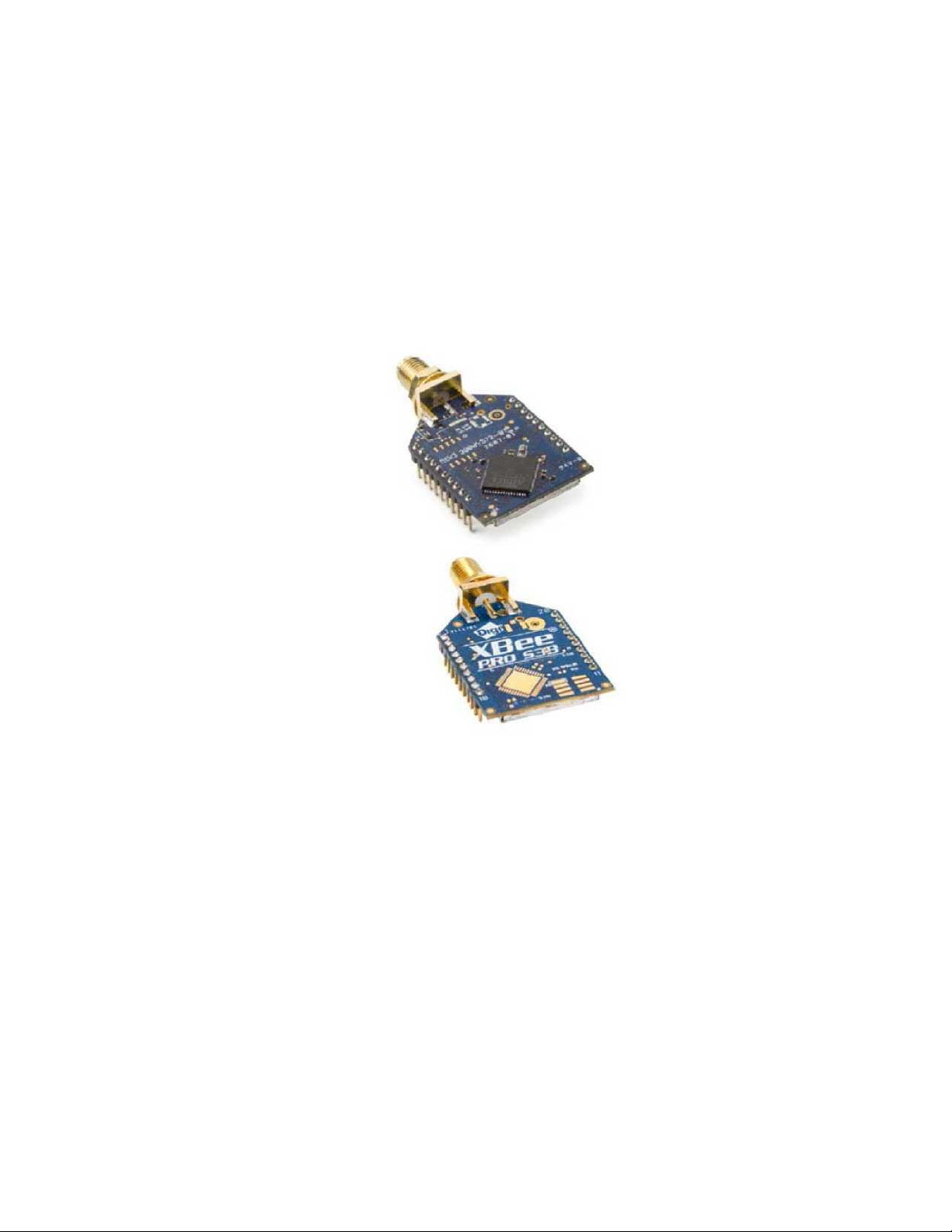
XBee-PRO® 900HP/XBee-PRO® XSC RF Modules
XBee-PRO RF Modules
Models: XBEE-PRO S3, XBEE-PRO S3B
Hardware: S3, S3B
90002173_L
2/4/2014

XBee-PRO® 900HP/XBee-PRO® XSC RF Modules
© 2014
1. XBee-PRO 900HP RF Module Hardware
This manual describes the operation of the XBee-PRO® 900HP RF module, which consists of firmware loaded onto XBee- PRO
S3B hardware.
XBee-PRO 900HP embedded RF modules provide wireless connectivity to end-point devices in mesh networks. Utilizing the
XBee-PRO Feature Set, these modules are interoperable with other devices. With the XBee, users can have their network
up-and-running in a matter of minutes without configuration or additional development.
XBee-PRO S3B Hardware Description
The XBee-PRO S3B radio module hardware consists of an Energy Micro EFM32G230F128 microcontroller, an Analog
Devices ADF7023 radio transceiver, an RF power amplifier, and in the programmable version, a Freescale
MC9S08QE32 microcontroller.
XBee-PRO 900HP Specifications
XBee-PRO® 900HP/XBee-PRO® XSC RF Modules
© 2014
3
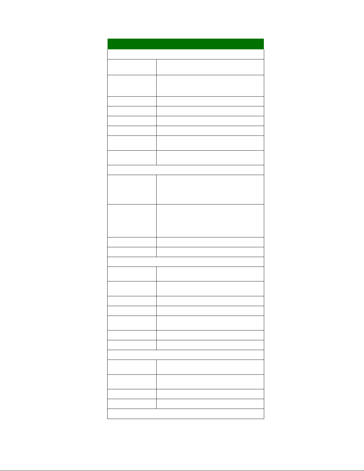
Specifications of the XBee-PRO® 900HP/XBee-PRO® XSC RF Module
Specification
XBee
Performance
* Indoor/Urban Range
10kbps: up to 2000 ft (610m) 200kbps: up to 1000 ft (305m)
* Outdoor RF line-of-sight Range
10kbps: up to 9 miles (15.5km) 200kbps: up to 4 miles (6.5km) (with
2.1dB dipole antennas)
Transmit Power Output 24 dBm (250 mW) (software selectable)
RF Data Rate (High)
200 kbps
RF Data Rate (Low)
10 kbps
Serial UART interface
CMOS Serial UART, baud rate stability of <1%
Serial Interface Data Rate
(software selectable)
9600-230400 baud
Receiver Sensitivity (typical)
-101 dBm, high data rate, -110 dBm, low data rate
Power Requirements
Supply Voltage
2.1 to 3.6 VDC**
**Supply voltages of less than 3.0V may result in
reduced performance. Output power and
receiver sensitivity may be degraded.
Transmit Current
PL=1 : 95mA typical PL=0 : 60mA typical
Idle / Receive Current 29mA typical at 3.3V, (35mA max)
Sleep Current
2.5 pA (typical)
General
**Operating Frequency Band
902 to 928 MHz (software selectable channels)
Dimensions
1.297” x 0.962” x 0.215 (3.29cm x 2.44cm x 0.546cm )
Note
: Dimensions
do not include connector/antenna or pin lengths
Weight 5 to 8 grams, depending on the antenna option
Operating Temperature -40° to 85° C (industrial)
Antenna Options
Integrated wire, U. FL RF connector, Reverse-polarity SMA connector
tal I/O
15 I/O lines,
ADC
4 10-bit analog inputs
Networking & Security
Supported Network Topologies
Mesh, point-to-point, point-to-multipoint, peer-to-peer
Number of Channels, user
selectable channels
64 channels available
Addressing Options PAN ID, Preamble ID, and 64-bit addresses
Encryption
128 bit AES
Agency Approvals
Specifications of the XBee-PRO® 900HP/XBee-PRO® XSC RF Module
* To determine your range, perform a range test under your operating conditions.
XBee-PRO® 900HP/XBee-PRO® XSC RF Modules
© 2014
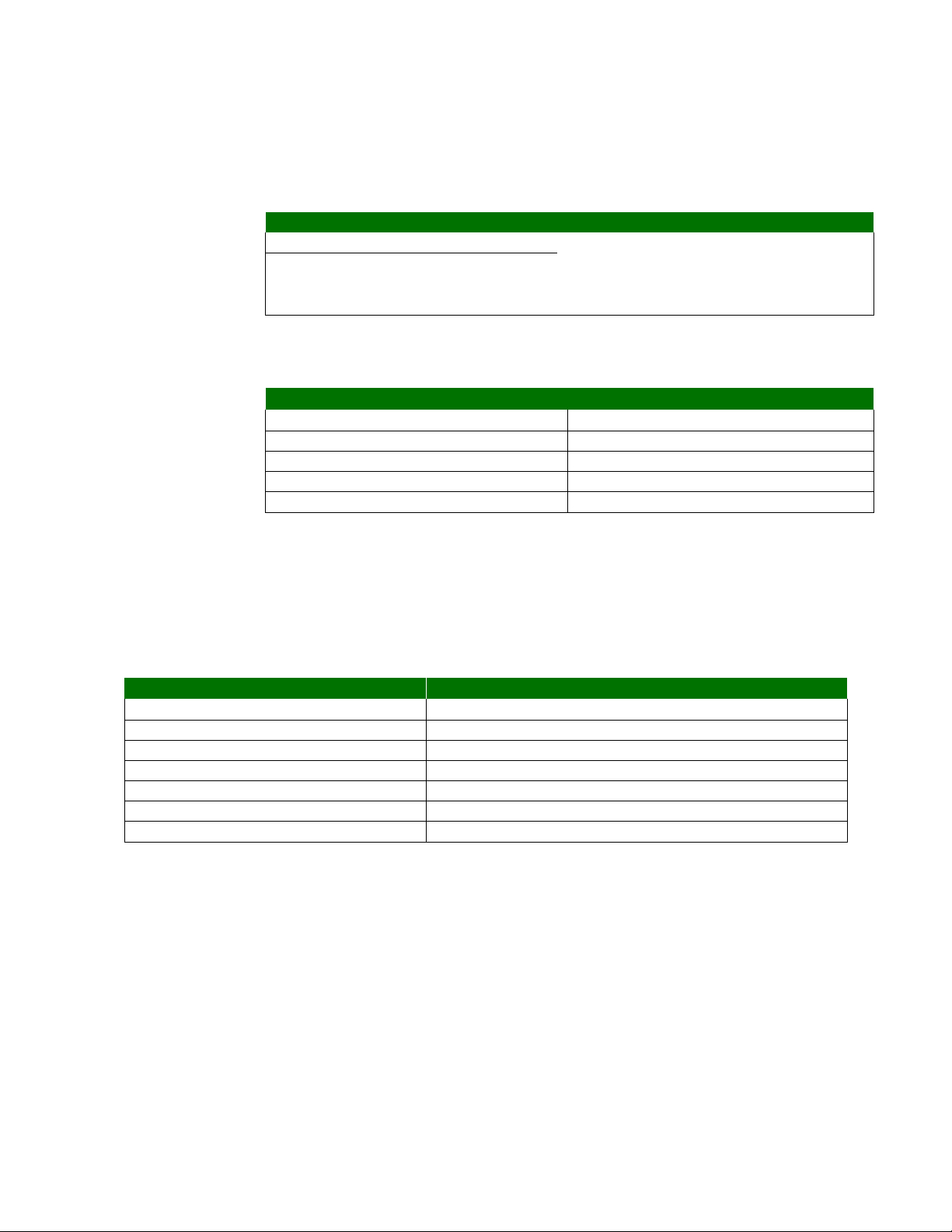
UART Pin Assignments
UART Pins
Module Pin Number
DOUT
2
DIN / CONFIG 3
CTS / DIO7
12
RTS / DIO6
16
SPI Pin Assignments
SPI Pins
Module Pin Number
SPI_SCLK / DIO18
18
SPLSSEL / DIO17
17
SPI_MOSI / DIO16
11
SPI_MISO / DIO15
4
SPI_ATTN / DIO1
19
Electrical Specifications for GPIO Pins
GPIO Electrical Specification
Value
Voltage - Supply
2.1 - 3.6 V, (3.0V or higher required for optimal performance)
Low Schmitt switching threshold 0.3 x Vdd
High Schmitt switching threshold 0.7 x Vdd
Input pull-up resistor value 40 kQ
Input pull-down resistor value 40 kQ
Output voltage for logic 0 0.05 x Vdd
Output voltage for logic 1 0.95 x Vdd
XBee-PRO 900HP Serial Communications Specifications
XBee RF modules support both UART (Universal Asynchronous Receiver / Transmitter) and SPI (Serial Peripheral
Interface) serial connections.
UART
More information on UART operation is found in the UART section in Chapter 2.
SPI
For more information on SPI operation, see the SPI section in Chapter 2.
GPIO Specifications
XBee RF modules have 15 GPIO (General Purpose Input/Output) ports available. The exact list will depend on the module
configuration, as some GPIO pins are used for purposes such as serial communication.
See GPIO section for more information on configuring and using GPIO ports.

XBee-PRO® 900HP/XBee-PRO® XSC RF Modules
© 2014
Electrical Specifications for GPIO Pins
GPIO Electrical Specification
Value
Output source current
2 mA
Output sink current
2 mA
Total output current (for GPIO pins)
48 mA
Specifications of the programmable secondary processor
Optional Secondary Processor Specification
These numbers add to specifications (Add to RX, TX, and
sleep currents depending on mode of operation)
Runtime current for 32k running at 20MHz
+14mA
Runtime current for 32k running at 1MHz
+1mA
Sleep current
+0.5pA typical
For additional specifications see Freescale Datasheet and Manual
MC9SO8QE32
Voltage requirement for secondary processor to operate at maximum clock
frequency
2.4 to 3.6VDC
Minimum Reset Pulse for Programmable
100nS
Minimum Reset Pulse to Radio
50nS
VREF Range
1.8VDC to VCC
Hardware Specifications for Programmable Variant
If the module has the programmable secondary processor, add the following table values to the specifications listed on
page 7. For example, if the secondary processor is running at 20 MHz and the primary processor is in receive mode then
the new current value will be I
processor and I
is the receive current of the primary.
rx
l = Ir2 + Irx = 14 mA + 9 mA = 23 mA, where Ir2 is the runtime current of the secondary
tota

XBee-PRO 900HP Pin Signals
XBee-PRO® 900HP/XBee-PRO® XSC RF Modules
© 2014 6
Mechanical drawings of the XBee-PRO 900HP RF Modules (antenna options not shown). All dimensions are in inches.
XBee-PW )
XBee & XBee-PRO
(top view)
□ . 02 "-"
! 6 k Li
Jncrr.
□.
SlnraJ
PJL
N i
Pin 10 —
_
7Z . PQimr
2-
I0.79IW,: (2.7gmn)
17
Mm
— i-
IK . i
(I, fr,'4
* .Obirin
A
.
00fWT..i
UrllB*
i II a J drror
r

XBee-PRO 900HP Mechanical Drawings
XBee-PRO® 900HP/XBee-PRO® XSC RF Modules
© 2014 7
Pin Assignments for XBee Modules
(Low-asserted signals are distinguished with a horizontal line above signal name.)
Pin #
Name
Direction
Default State
Description
1
VCC
Power Supply
2
DOUT/DIO13
Both Output GPIO / UART Data out
3 DIN/nConfig/DIO14
Both Input GPIO / UART Data In
4 DIO12/SPI_MISO
Both Output GPIO / SPI slave out
5 nRESET
Input
Module Reset. Drive low to reset the module. This is also an
output with an open drain configuration with an internal 20 K
ohm pull-up (never drive to logic high, as the module may be
driving it low).
The minimum pulse width is 1 mS.
6 DIO10/PWM0
Both
GPIO / RX Signal Strength Indicator
7 DIO11/PWM1
Both
GPIO / Pulse Width Modulator
8 reserved
Disabled Do Not Connect
9 nDTR/SLEEP_RQ/DIO8
Both Input
GPIO / Pin Sleep Control Line (DTR on the dev board)
10 GND
Ground
11 DIO4/AD4/SPI_MOSI
Both
GPIO/SPI slave In
12
nCTS/DIO7
Both Output GPIO / Clear-to-Send Flow Control
13 On_nSLEEP/DIO9
Output Output GPIO / Module Status Indicator
14 VREF
Input
Internally used for programmable secondary processor. For
compatibility with other XBee modules, we recommend
connecting this pin to the voltage reference if Analog Sampling
is desired. Otherwise, connect to GND.
15 Associate/DIO5
Both Output GPIO / Associate Indicator
16 nRTS/DIO6
Both Input GPIO / Request-to-Send Flow Control
17 AD3/DIO3/SPI_nSSEL
Both
GPIO / Analog Input / SPI Slave Select
18
AD2/DIO2/SPI_CLK
Both
GPIO / Analog Input / SPI Clock
19 AD1/DIO1/SPI_nATTN
Both
GPIO / Analog Input / SPI Attention
20 AD0/DIO0
Both
GPIO / Analog Input
XBee-PRO 900HP Design Notes
The XBee modules do not specifically require any external circuitry or specific connections for proper operation. However, there are some general design guidelines that are
recommended for help in troubleshooting and building a robust design.
XBee-PRO 900HP Power Supply Design
Poor power supply can lead to poor radio performance, especially if the supply voltage is not kept within tolerance or is exc essively noisy. To help reduce noise, we recommend
placing both a 1^F and 47pF capacitor as near to pin 1 on the PCB as possible. If using a switching regulator for your power supply, switching frequencies above 500kHz are
preferred. Power supply ripple should be limited to a maximum 50mV peak to peak.
Note - For designs using the programmable modules, an additional 10^F decoupling cap is recommended near pin 1 of the module. The nearest proximity to pin 1 of the three caps
should be in the following order: 47pf, 1^F followed by 10^F.
XBee-PRO 900HP Recommended Pin Connections
The only required pin connections are VCC, GND, DOUT and DIN. To support serial firmware updates, VCC, GND, DOUT, DIN, RTS, and DTR should be connected.
• Signal Direction is specified with respect to the module
• See Design Notes section below for details on pin connections.

All unused pins should be left disconnected. All inputs on the radio can be pulled high or low with 40k internal pull-up or
pull-down resistors using the PR and PD software commands. No specific treatment is needed for unused outputs.
For applications that need to ensure the lowest sleep current, unconnected inputs should never be left floating. Use
internal or external pull-up or pull-down resistors, or set the unused I/O lines to outputs.
Other pins may be connected to external circuitry for convenience of operation, including the Associate LED pin (pin 15)
and the Commissioning pin (pin 20). An LED attached to the the associate LED pin will flash differently depending on
the state of the module to the network, and a pushbutton attached to pin 20 can enable various join functions without
having to send serial port commands. Please see the commissioning pushbutton and associate LED section in chapter
7 for more details. The source and sink capabilities are limited to 6mA on all I/O pins.
The VRef pin (pin 14) is only used on the programmable versions of these modules. For compatibility with other XBee
modules, we recommend connecting this pin to a voltage reference if analog sampling is desired. Otherwise, connect to
GND.
XBee-PRO 900HP Board Layout
XBee modules are designed to be self sufficient and have minimal sensitivity to nearby processors, crystals or other
PCB components. As with all PCB designs, Power and Ground traces should be thicker than signal traces and able to
comfortably support the maximum current specifications. No other special PCB design considerations are required for
integrating XBee radios except in the antenna section.
The choice of antenna and antenna location is very important for correct performance. XBees do not require additional
ground planes on the host PCB. In general, antenna elements radiate perpendicular to the direction they point. Thus a
vertical antenna emits across the horizon. Metal objects near the antenna cause reflections and may reduce the ability
for an antenna to radiate efficiently. Metal objects between the transmitter and receiver can also block the radiation path
or reduce the transmission distance, so external antennas should be positioned away from them as much as possible.
Some objects that are often overlooked are metal poles, metal studs or beams in structures, concrete (it is usually
reinforced with metal rods), metal enclosures, vehicles, elevators, ventilation ducts, refrigerators, microwave ovens,
batteries, and tall electrolytic capacitors.
XBee-PRO 900HP Module Operation for Programmable Variant
The modules with the programmable option have a secondary processor with 32k of flash and 2k of RAM. This allows
module integrators to put custom code on the XBee module to fit their own unique needs. The DIN, DOUT, RTS, CTS,
and RESET lines are intercepted by the secondary processor to allow it to be in control of the data transmitted and
received. All other lines are in parallel and can be controlled by either the internal microcontroller or the MC9SO8QE
micro (see Block Diagram for details). The internal microcontroller by default has control of certain lines. These lines
can be released by the internal microcontroller by sending the proper command(s) to disable the desired DIO line(s)
(see XBee Command Reference Tables).
In order for the secondary processor to sample with ADCs, the XBee pin 14 (VREF) must be connected to a reference
voltage.
provides a bootloader that can take care of programming the processor over the air or through the serial interface. This
means that over the air updates can be supported through an XMODEM protocol. The processor can also be
programmed and debugged through a one wire interface BKGD (Pin 8).

XBee-PRO® 900HP/XBee-PRO® XSC RF Modules
©
2014
K-l
XBee
-
PRO® 900HP/XBee
-
PRO® XSC RF Modules

© 2014 10
Appendix A: Agency Certifications for S3B
Hardware
Please note that both Appendix B and Appendix C contain Agency Certification information. Please refer to the Preface for instructions on which appendix
applies to your product.
FCC (United States) Certification
The XBee-PRO® 900HP/XBee-PRO® XSC RF Module complies with Part 15 of the FCC rules and regulations. Compliance with the labeling requirements,
FCC notices and antenna usage guidelines is required.
In order to operate under 's FCC Certification, RF Modules/integrators must comply with the following regulations:
1. The system integrator must ensure that the text provided with this device [Figure A-01] is placed on the outside of the final product
and within the final product operation manual.
2. The XBee-PRO® 900HP/XBee-PRO® XSC RF Module may only be used with antennas that have been tested and approved for
use with this module refer to Table A-1.
Labeling Requirements
Warning: Changes or modifications to this unit not expressly approved by the party responsible for compliance could void the user’s authority to operate the
equipment.
This device complies with Part 15 of the FCC Rules. Operation is subject to the following two conditions:
(1) this device may not cause harmful interference, and (2) this device must accept any interference received, including interference that may cause
undesired operation.
Host labeling requirement: Contains transmitter module FCC ID: 2AQWE-XB900HP
FCC Notices
IMPORTANT: The XBee-PRO® 900HP/XBee-PRO® XSC OEM RF Module has been certified by the FCC for use with other products without any
further certification (as per FCC section 2.1091). Modifications not expressly approved by could void the user's authority to operate the equipment.
IMPORTANT: OEMs must test final product to comply with unintentional radiators (FCC section 15.107 & 15.109) before declaring compliance of their
final product to Part 15 of the FCC Rules.
IMPORTANT: The RF module has been certified for remote and base radio applications. If the module will be used for portable applications, the device
must undergo SAR testing.
IMPORTANT:
This equipment has been tested and found to comply with the limits for a Class B tal device, pursuant to Part 15 of the FCC Rules. These limits are
designed to provide reasonable protection against harmful interference in a residential installation. This equipment generates, uses and can radiate radio
frequency energy and, if not installed and used in accordance with the instructions, may cause harmful interference to radio communications. However,
there is no guarantee that interference will not occur in a particular installation.
If this equipment does cause harmful interference to radio or television reception, which can be determined by turning the equipment off and on, the user is
encouraged to try to correct the interference by one or more of the following measures: Re-orient or relocate the receiving antenna, Increase the separation
between the equipment and receiver, Connect equipment and receiver to outlets on different circuits, or Consult the dealer or an experienced radio/TV
technician for help.
Limited Modular Approval
This is an RF module approved for Limited Modular use operating as a mobile transmitting device with respect to section 2.1091 and is limited to OEM
installation for Mobile and Fixed applications only. During final installation, end-users are prohibited from access to any programming parameters. Professional
installation adjustment is required for setting module power and antenna gain to meet EIRP compliance for high gain antenna(s).
Final antenna installation and operating configurations of this transmitter including antenna gain and cable loss must not exceed the EIRP of the configuration
used for calculating MPE. Grantee () must coordinate with OEM integrators to ensure the end-users and installers of products operating with the module are
provided with operating instructions to satisfy RF exposure requirements.
The FCC grant is valid only when the device is sold to OEM integrators. Integrators are instructed to ensure the end-user has no manual instructions to remove,
adjust or install the device.

The Omni-directional antenna below has been approved for use with this module when installed into the host device (Host Device FCC ID:
2AQWE-GC170424). The antenna Gain with Cable loss is less than 6dBi.
FCC-approved Antennas
A WARNING: This device has been tested with Reverse Polarity SMA connectors as below. When integrated into OEM products, fixed antennas require
installation preventing end-users from replacing them with non-approved antennas. Other antennas excepted below one must be tested to comply
with FCC Section 15.203 (unique antenna connectors), Section 15.247 (emissions) and RF exposure when the module installed into the host
device indicated in this filling.
WARNING: The FCC requires that all spread spectrum devices operating within the Unlicensed radio frequency bands must limit themselves to a maximum
radiated power of 4 Watts EIRP. Failure to observe this limit is a violation of our warranty terms, and shall void the user's authority to operate the equipment.
This can be stated: RF power - cable loss + antenna gain <= 36 dBm eirp.
Fixed Base Station and Mobile Applications
RF Modules are pre-FCC approved for use in fixed base station and mobile applications. When the antenna is mounted at least 20cm (8") from nearby persons,
the application is considered a mobile application.
Portable Applications and SAR Testing
If the module will be used at distances closer than 20cm to all persons, the device may be required to undergo SAR testing. Co-location with other transmitting
antennas closer than 20cm should be avoided.
RF Exposure
This statement must be included as a CAUTION statement in OEM product manuals.
A WARNING: This equipment is approved only for mobile and base station transmitting devices.
Antenna(s) used for this transmitter must be installed to provide a separation distance of at least 20 *cm from all persons and must not be
co-located or operating in conjunction with any other antenna or transmitter.
Photo of the Omni-directional antenna used when device installed into the host device indicated above.
 Loading...