

Page 1
BD_BE 719 a, ADPR1X714024 02/2016
S# 11586738
tecsis GmbH
Carl-Legien-Str. 40-44
63073 Offenbach / Germany
Phone: +49 69 5806-0
Fax: +49 69 5806-170
E-Mail: [email protected]
www.tecsis.de
Betriebsanleitung
Operating instructions
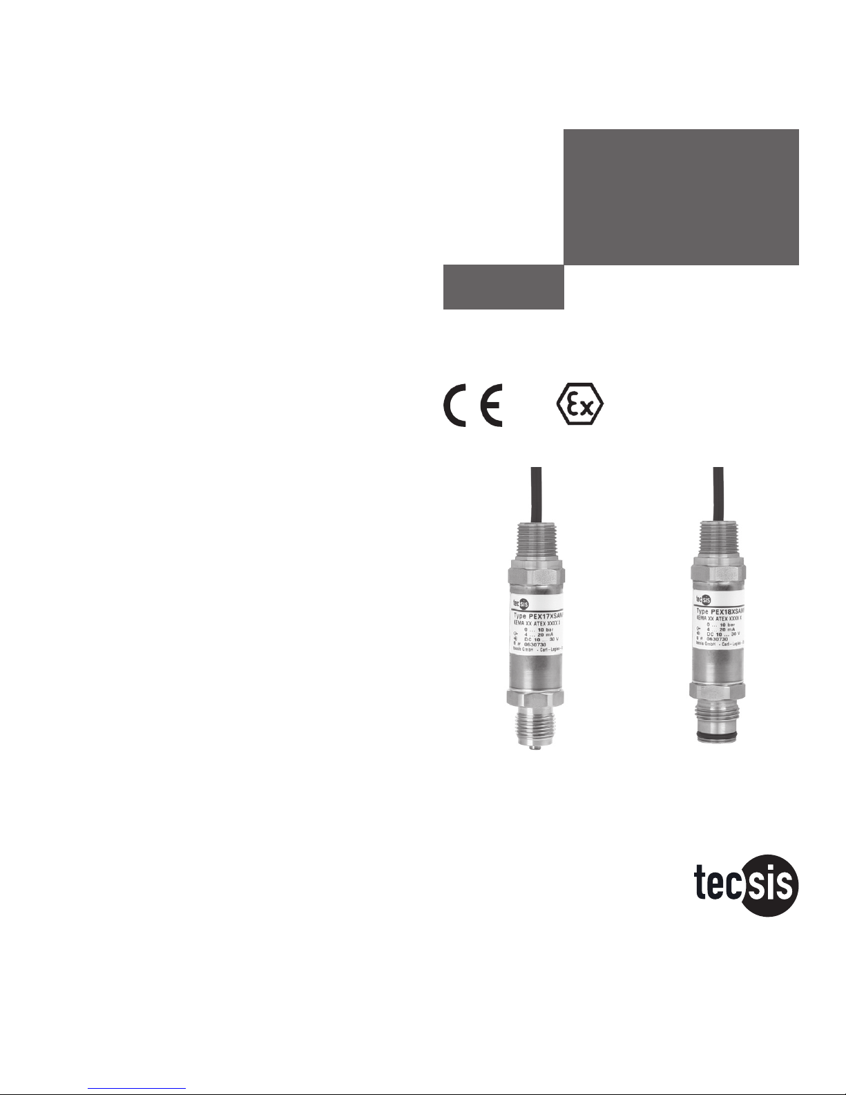
PEX17,
PEX18
Drucksensoren /
Pressure sensors
PEX17
PEX18
Page 2

BD_BE 719 a
2 Betriebsanleitung/Operating instructions
Contents Page 18-32 GB
1. Important details for your information 18
2. A quick overview for you 19
3. Signs, symbols and abbreviations 19
4. Function 19
5. For your safety 20
6. Packaging 21
7.
Starting, operation 21
8. Maintenance, accessories 28
9. Trouble shooting 28
10. Storage, disposal 30
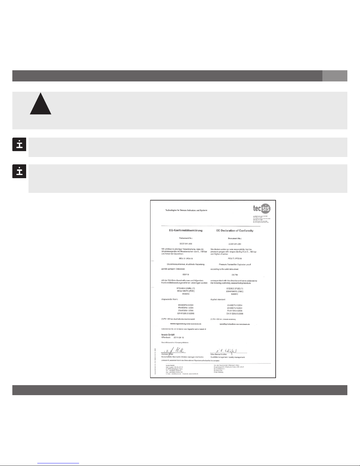
11. EC declaration of conformity 30
12. EC-Type Examination Certificate 31
Inhalt Seite 3-17 D
1. Wichtiges zu Ihrer Information 3
2. Der schnelle Überblick für Sie 4
3. Zeichenerklärungen, Abkürzungen 4
4. Funktion 4
5. Zu Ihrer Sicherheit 5
6. Verpackung 6
7.
Inbetriebnahme, Betrieb 6
8. Wartung, Zubehör 13
9. Störbeseitigung 13
10. Lagerung, Entsorgung 15
11. EG-Konformitätserklärung 15
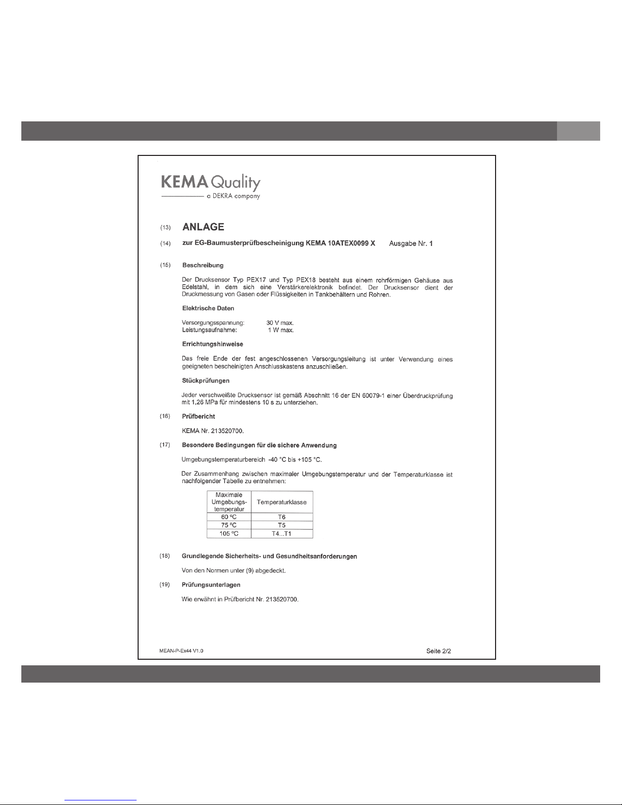
12. EG-Baumusterprüfbescheinigung 16
Inhalt / Contents
D GB
Current terms and conditions apply
details are available on
Es gelten unsere aktuellen Verkaufsund Lieferbedingungen siehe unter
www.tecsis.de
Page 3

BD_BE 719 a
3Betriebsanleitung/Operating instructions
1. Wichiges zu Ihrer Information
D
Zulassung ATEX:
Druckmessgerät zur bestimmungsgemäßen Verwendung in explosionsgefährdeten Bereichen
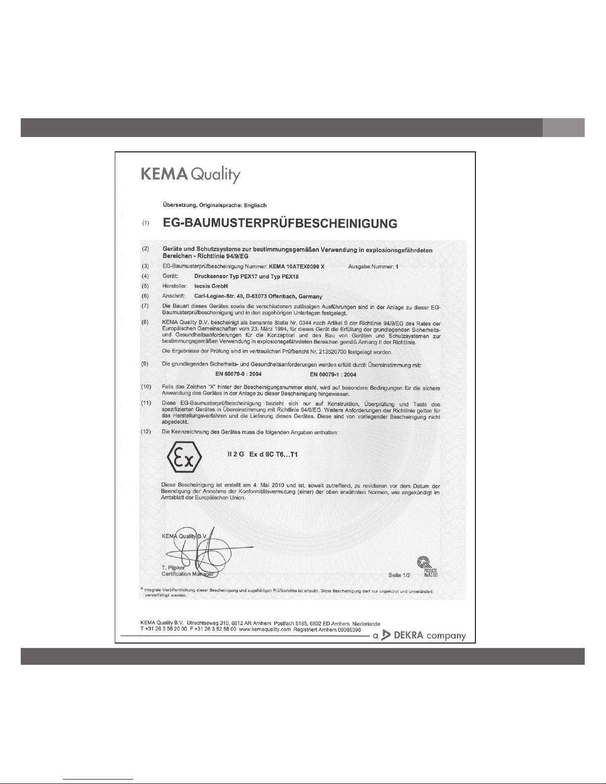
(siehe EG-Baumusterprüfbescheinigung KEMA 10ATEX0099 X).
ATEX Zulassungseigenschaften: druckfeste Kapselung II 2 G Ex d II C T6 ... T1
1. Wichtiges zu Ihrer Information
Lesen Sie diese Betriebsanleitung vor Montage und Inbetriebnahme des Druckmessgerätes.
Bewahren Sie die Betriebsanleitung an einem für alle Benutzer jederzeit zugänglichen Ort auf.
Die nachfolgenden Einbau- und Betriebshinweise haben wir mit Sorgfalt zusammengestellt.
Es ist jedoch nicht möglich, alle erdenklichen Anwendungsfälle zu berücksichtigen. Sollten Sie
Hinweise für Ihre spezielle Aufgabenstellung vermissen, können Sie hier weitere Informationen
finden:
Über unsere Internet-Adresse www.tecsis.de
Die Bezeichnung des zugehörigen Datenblattes ist DD719/DE719
Anwendungsberater: +49 69 5806-0
Wird die Seriennummer auf dem Typenschild und/oder der 2D-Code auf dem Sechskant unleserlich (z. B. durch mechanische Beschädigung oder Übermalen), ist eine Rückverfolgbarkeit
nicht mehr möglich.
Die in der Betriebsanleitung beschriebenen tecsis-Druckmessgeräte werden nach den
neuesten Erkenntnissen konstruiert und gefertigt. Alle Komponenten unterliegen während der
Fertigung strengen Qualitäts- und Umweltkriterien.
Bestimmungsgemäße Produktverwendung PEX17, PEX18:
Verwenden Sie das Druckmessgerät mit druckfester Kapselung, um in explosionsgefährdeten
Bereichen Druck in ein elektrisches Signal zu wandeln.
Ihre erforderlichen Kenntnisse
Montieren und nehmen Sie das Druckmessgerät nur in Betrieb, wenn Sie mit den zutreffenden
landesspezifischen Richtlinien vertraut sind und die entsprechende Qualifikation besitzen.
Sie müssen mit den Vorschriften und Kenntnissen für explosionsgefährdete Bereiche, Messund Regeltechnik sowie elektrische Stromkreise vertraut sein, da das Druckmessgerät ein
„elektrisches Betriebsmittel“ nach EN 50178 ist. Je nach Einsatzbedingung müssen Sie über
entsprechendes Wissen verfügen, z. B. über agressive Medien.
Page 4
BD_BE 719 a
4 Betriebsanleitung/Operating instructions
2. Schneller Überblick / 3. Zeichenerklärungen, Abkürzungen / 4. Funktion
D
2. Der schnelle Überblick für Sie
Wollen Sie sich einen schnellen Überblick verschaffen, lesen Sie Kapitel 3, 5, 7 und 10. Dort
erhalten Sie kurze Hinweise zu Ihrer Sicherheit und wichtige Informationen über Ihr Produkt
und zur Inbetriebnahme. Lesen Sie diese unbedingt.
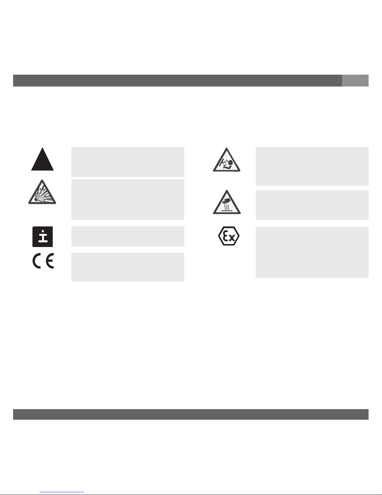
3. Zeichenerklärungen, Abkürzungen
Mögliche Gefahr für Ihr
Leben oder schwerer
Verletzungen.
Ex-Hinweise:
Mögliche Gefahr für Ihr
Leben oder schwerer
Verletzungen.
Mögliche Gefahr für Ihr
Leben oder schwerer
Verletzungen durch
wegschleudernde Teile.
Mögliche Gefahr von
Verbrennungen durch
heisse Oberflächen.
Hinweis, wichtige Information, Funktionsstörung.
Das Produkt stimmt mit den
zutreffenden europäischen
Richtlinien überein.
Das Produkt stimmt überein
mit den Anforderungen der
europäischen Richtlinie
94/9/EG (ATEX) zum
Explosionsschutz.
2-Leiter Zwei Anschlussleitungen dienen zur Spannungsversorgung.
Der Speisestrom ist das Mess-Signal.
3-Leiter Zwei Anschlussleitungen dienen zur Spannungsversorgung.
Eine Anschlussleitung dient für das Mess-Signal.
ATEX Europäische Explosionsschutz-Richtlinie (Atmosphäre=AT, Explosion=EX)
4. Funktion
PEX17: Druckanschluss (druckfeste Kapselung) mit innenliegender Membran
(Standardausführung)
PEX18: Druckanschluss (druckfeste Kapselung) mit frontbündiger Membrane für hoch viskose oder kristallisierende Medien, die die Bohrung des Druckanschlusses
zusetzen können.
Warnung
Vorsicht
!
Warnung
Warnung
Page 5
BD_BE 719 a
5Betriebsanleitung/Operating instructions
4. Funktion / 5. Zu Ihrer Sicherheit
D
Funktion: Mittels Sensorelement und unter Zuführung von Hilfsenergie wird über die Verformung einer Membran der anstehende Druck in Ihrer Anwendung in ein verstärktes standardisiertes elektrisches Signal umgewandelt. Dieses elektrische Signal verändert sich proportional
zum Druck und kann entsprechend ausgewertet werden.
Beachten Sie die Angaben der geltenden Baumusterprüfbescheinigung sowie
die jeweiligen landesspezifischen Vorschriften zur Installation und Einsatz in
explosionsgefährdeten Bereichen (z.B.: IEC 60079-14). Wenn Sie diese nicht
beachten, können schwere Körperverletzungen und Sachschäden entstehen.
5. Zu Ihrer Sicherheit
Wählen Sie das richtige Druckmessgerät hinsichtlich Messbereich, Ausfüh-
rung und spezifischen Messbedingungen vor Montage oder Inbetriebnahme.
Halten Sie die entsprechenden landesspezifischen Vorschriften ein (z. B.: EN
50178) und beachten Sie bei speziellen Anwendungen die geltenden Normen
und Richtlinien (z. B. bei gefährlichen Messstoffen wie Acetylen, brennbaren
oder giftigen Stoffen sowie bei Kälteanlagen und Kompressoren). Wenn Sie
die entsprechenden Vorschriften nicht beachten, können schwere Körperver-
letzungen und Sachschäden entstehen!
Öffnen Sie Anschlüsse nur im drucklosen Zustand!
Betreiben Sie das Druckmessgerät immer innerhalb des Überlastgrenzbereiches!
Beachten Sie die Betriebsparameter gemäß Punkt 7 „Technische Daten“.
Stellen Sie sicher, dass das Druckmessgerät nur bestimmungsgemäß -also wie in der
folgenden Anleitung beschrieben- betrieben wird.
Unterlassen Sie unzulässige Eingriffe und Änderungen am Druckmessgerät, welche nicht
in dieser Betriebsanleitung beschrieben sind.
Setzen Sie das Druckmessgerät außer Betrieb und schützen Sie es gegen versehentliche
Inbetriebnahme, wenn Sie Störungen nicht beseitigen können.
Ergreifen Sie Vorsichtsmaßnahmen für Messstoffreste in ausgebauten Druckmessgeräten.
Messstoffreste können zur Gefährdung von Menschen, Umwelt und Einrichtung führen!
Lassen Sie Reparaturen nur vom Hersteller durchführen.
Warnung
!
Warnung
Page 6
BD_BE 719 a
6 Betriebsanleitung/Operating instructions
6. Verpackung / 7. Inbetriebnahme, Betrieb
D
6. Verpackung
Zum Schutz der Membran ist der Druckanschluss des Gerätes PEX18 mit einer speziellen
Schutzkappe versehen.
7. Inbetriebnahme, Betrieb
Es ist erforderlich, dass Sie vor Inbetriebnahme des Druckmessgerätes die Membran prüfen,
denn sie ist ein sicherheitsrelevantes Teil.
Überprüfen Sie den Lieferumfang:
Komplett montierte Druckmessgeräte; bei frontbündiger Ausführung PEX18 mit
vormontierten Dichtungen und Schutzkappe.
Untersuchen Sie das Druckmessgerät auf eventuell entstandene Transportschäden.
Sind offensichtlich Schäden vorhanden, teilen Sie dies dem Transportunternehmen
und tecsis unverzüglich mit.
Bewahren Sie die Verpackung auf, denn diese bietet bei einem Transport einen
optimalen Schutz (z. B. wechselnder Einbauort, Reparatursendung).
Achten sie darauf, dass das Druckanschluss-Gewinde und die Anschlusskontakte nicht
beschädigt werden.
Entfernen Sie diese Schutzkappe erst kurz vor dem Einbau, damit die Membran bzw.
das Druckanschluss-Gewinde nicht beschädigt wird.
Bewahren Sie die Schutzkappe des Druckanschluss-Gewindes und der Membran zur
späteren Lagerung oder Transport auf.
Montieren Sie die Schutzkappe bei Ausbau und Transport des Gerätes.
Benötigtes Werkzeug: Maulschlüssel SW 27, Schraubendreher
Achten Sie auf auslaufende Flüssigkeit, denn sie ist ein Hinweis auf eine
Membranbeschädigung.
Prüfen Sie die Membran optisch auf Beschädigung (PEX18).
Setzen Sie das Druckmessgerät nur ein, wenn die Membran unbeschädigt
ist.
Setzen Sie das Druckmessgerät nur in sicherheitstechnisch einwandfreiem
Zustand ein.
Membran-Prüfung zu Ihrer Sicherheit
Wurde alles geliefert?
!
Warnung
Page 7
BD_BE 719 a
7Betriebsanleitung/Operating instructions
7. Inbetriebnahme, Betrieb
D
Montage mechanischer Anschluss
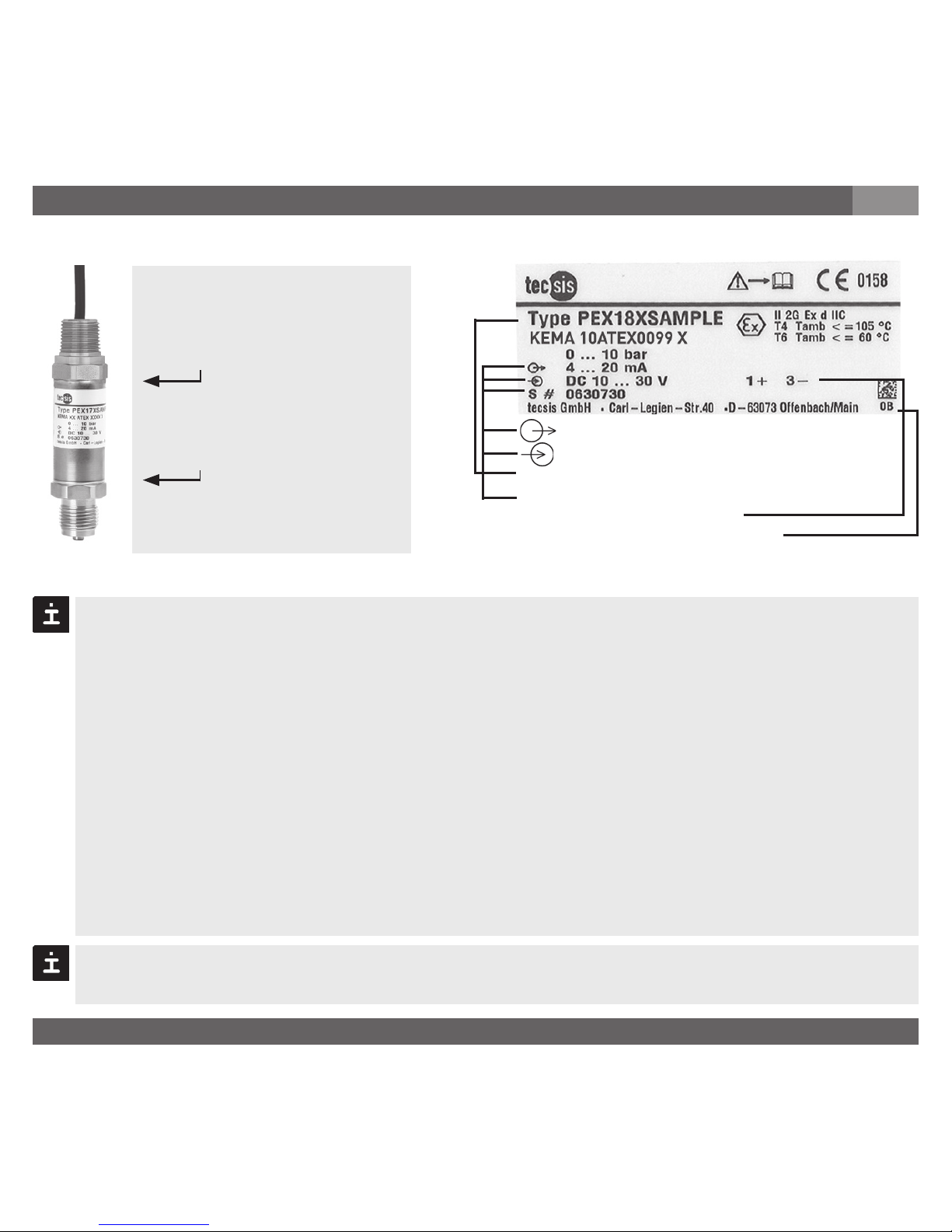
Signal
Spannungsversorgung
Erzeugnis-Nr.
Serien-Nr.
Anschlussbelegung
Codiertes Herstelldatum
Typenschild (Beispiel)
Befindet sich keine Seriennummer auf dem Typenschild, so gilt die Nummer auf dem Sechskant.
P #
Entfernen Sie die Schutzkappe erst kurz vor dem Einbau und achten Sie unbedingt
darauf, dass die Membran auch während des Einbaus nicht beschädigt wird (PEX18).
Bei Typ PEX17 müssen Sie eine Dichtung vorsehen; Ausnahme sind Geräte mit selbst
dichtendem Gewinde (z. B. NPT-Gewinde).
Bei Typ PEX18 ist der Dichtring im Lieferumfang enthalten.
Achten Sie bei der Montage auf saubere und unbeschädigte Dichtflächen am Gerät und
Messstelle.
Schrauben Sie das Gerät nur über die Schlüsselflächen mit einem geeigneten Werk-
zeug und dem vorgeschriebenen Drehmoment ein bzw. aus. Das richtige Drehmoment
ist abhängig von der Dimension des Druckanschlusses sowie der verwendeten Dichtung (Form/Werkstoff). Verwenden Sie zum Ein- bzw. Ausschrauben nicht das Gehäuse
als Angriffsfläche.
Beachten Sie beim Einschrauben, dass die Gewindegänge nicht verkantet werden.
NmZur Montage des
Prozessanschlusses
verwenden
max. 50
S #
Nur zum Sichern des
Druckmessgeräts
während der Montage des
elektrischen Conduits
Achten Sie darauf, dass beim Einschrauben des Prozessanschlusses das Drehmoment
nicht größer als 50 Nm (36,9 Foot-Pound) sein darf.
Page 8
BD_BE 719 a
8 Betriebsanleitung/Operating instructions
7. Inbetriebnahme, Betrieb
D
Schützen Sie die Membran vor Kontakt mit abrasiven Medien und gegen
Schläge. Wenn Sie die Membran beschädigen, ist kein Explosionsschutz
gewährleistet (ATEX).
Betreiben Sie das Druckmessgerät nie außerhalb des Temperaturbereichs
von -40 ... +105 °C. Außerhalb dieses Bereiches ist der Explosionsschutz
nicht sichergestellt.
Halten Sie die zulässigen Oberflächentemperaturen ein, die für diesen Bereich auf Grund
der festgelegten Temperaturklassen gelten.
Montage elektrischer Anschluss
Erden Sie den Kabelschirm einseitig und bevorzugt im sicheren, also Nicht-
Ex-Bereich (EN 60079-14). Bei Geräten mit Kabelausgang ist der Schirm
mit dem Gehäuse verbunden. Der gleichzeitige Anschluss von Gehäuse und
Kabelschirm an Erde ist nur dann zulässig, wenn eine Potentialverschlep-
pung zwischen Schirmanschluss (z.B. am Speisegerät) und Gehäuse
ausgeschlossen werden kann (siehe EN 60079-14).
Schließen Sie das Gerät an eine Stromversorgung an, die mit einer Schutzmaßnahme
nach IEC 60364-4-41 (DN VDE 0100-410) ausgerüstet ist.
Versuchen Sie nicht, den Kabelanschluss zu entfernen. Dies führt zur Beschädigung des
Druckmessgeräts sowie zum sofortigen Erlöschen der Werksgewährleistung und der
Zulassung.
Der elektrische Anschluss am Druckmessgerät sollte so wie ursprünglich geliefert
verwendet werden. Er darf nicht umgangen oder verändert werden (mit Ausnahme
der Kabellänge). Durch unsachgemäße Montage oder Veränderung des elektrischen
Anschlusses wird die Explosionsschutzklasse, für die das Druckmessgerät zugelassen ist,
ungültig.
Erden Sie das Gehäuse über den Prozessanschluss immer gegen elektroma-
gnetische Felder und elektrostatische Aufladungen.
Warnung
Warnung
!
Warnung
Page 9
BD_BE 719 a
9Betriebsanleitung/Operating instructions
Betreiben Sie das Druckmessgerät mit geschirmter Leitung und erden Sie den Schirm
auf mindestens einer Leitungsseite, wenn die Leitungen länger als 30m (2-Leiter) bzw.
3m (3- bzw. 4-Leiter) sind oder das Gebäude verlassen.
Schutzart IP nach IEC 60 529
Stellen Sie bei Kabelausgängen sicher, dass am Ende des Kabels keine Feuchtigkeit
eintritt.
7. Inbetriebnahme, Betrieb
D
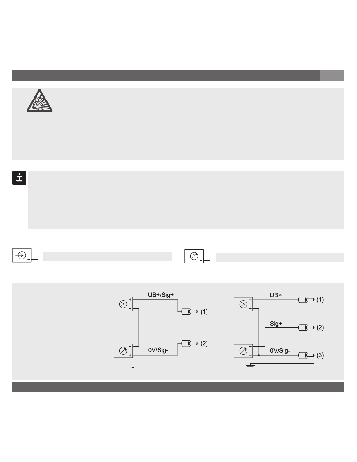
Verbraucher
Spannungsversorgung
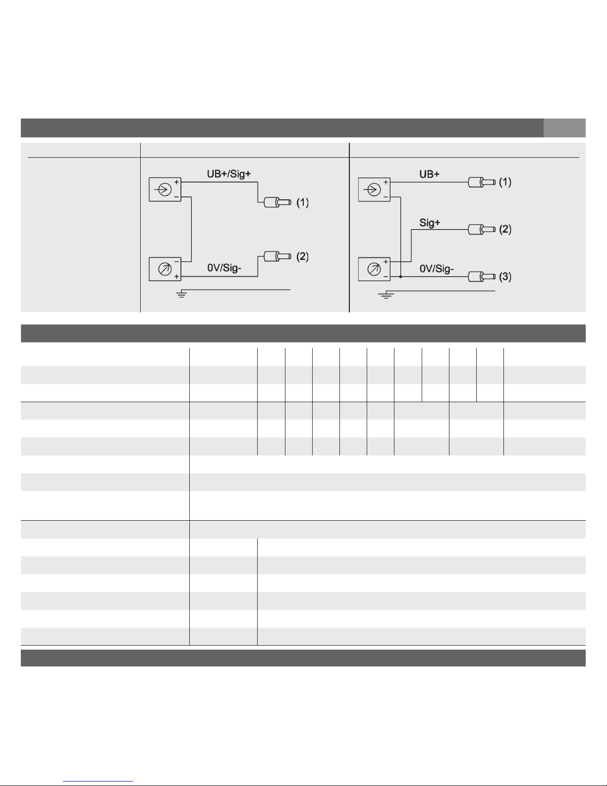
UB+/Sig+ Positiver Versorgungs- / Messanschluss
OV/Sig- Negativer Versorgungs- / Messanschluss
Kabelausgang
mit 2 m Länge,
IP 67
3-Leiter2-Leiter
rot
rot
schwarz
schwarz
braun
Schirm
(auf Gehäuse aufgelegt)
Versehen Sie feindrahtige Leiterenden mit Aderendhülsen (Kabelkonfektio-
nierung).
Bei Installationen mit Leitungsrohren verwenden Sie nur Gewinde NPT 1/2"
nach ANSI/AME B1.20.1. Verschrauben Sie diese so, dass sich mindestens
5 Gewindegänge im Eingriff befinden.
Klemmen Sie das freie Kabelende an einen geeigneten bescheinigten Klemmkasten an
oder außerhalb des explosionsgefährdeten Bereichs.
Schirm
(auf Gehäuse aufgelegt)
Warnung
Page 10
BD_BE 719 a
10 Betriebsanleitung/Operating instructions
Technische Daten Typ PEX17 / PEX18
Messbereich bar 0,4 0,6 1 1,6 2,5 4 6 10 16 25
Überlastgrenze bar 2 4 5 10 10 17 35 35 80 50
Berstdruck bar 2,4 4,8 6 12 12 20,5 42 42 96 96
Messbereich bar 40 60 100 160 250 400 600 1000
1)
Überlastgrenze bar 80 120 200 320 500 800 1200 1500
Berstdruck bar 400 550 800 1000 1200 1700
2)
2400
2)
3000
{Unterdruck, Überdruck, +/- , sowie Absolutdruck erhältlich}
1)
Nur für Typ PEX17 gültig.
2)
Bei Typ PEX18: Der Tabellenwert gilt ausschließlich bei Abdichtung mittels
Dichtring unterhalb vom Sechskant. Andernfalls gilt max. 1500 bar.
Werkstoff
Messstoffberührte Teile (andere Werkstoffe siehe tecsis Druckmittler-Programm)
» Typ PEX17 CrNi-Stahl (> 25 bar Elgiloy
®
)
» Typ PEX18 CrNi-Stahl
O-Ring: NBR {FPM/FKM}
Gehäuse CrNi-Stahl
Interne Übertragungsflüssigkeit
3)
Synthetisches Öl (nicht für PEX17 mit Messbereichen > 25 bar)
Hilfsenergie U
B UB in VDC 10 < UB ≤ 30 bei Ausgang 4 ... 20 mA, 2-Leiter
6 < U
B ≤ 30 bei Ausgang 1 ... 5 V, 3-Leiter
Ausgangssignal und zulässige 4 ... 20 mA, 2-Leiter
max. ohmsche Bürde R
A RA in Ohm RA ≤ (UB - 10 V) / 0,02 A
1 ... 5 V, 3-Leiter, RA > 10000
Einstellzeit (10 … 90 %) ms
≤
1 (≤ 10 ms bei Messstofftemperatur < -30 °C für Messbereiche bis
25 bar oder bei frontbündiger Membrane
Spannungsfestigkeit VDC 500
Genauigkeit % d. Spanne
≤
0,25 (BFSL)
≤
0,5
3)
7. Inbetriebnahme, Betrieb
D
Page 11
BD_BE 719 a
11Betriebsanleitung/Operating instructions
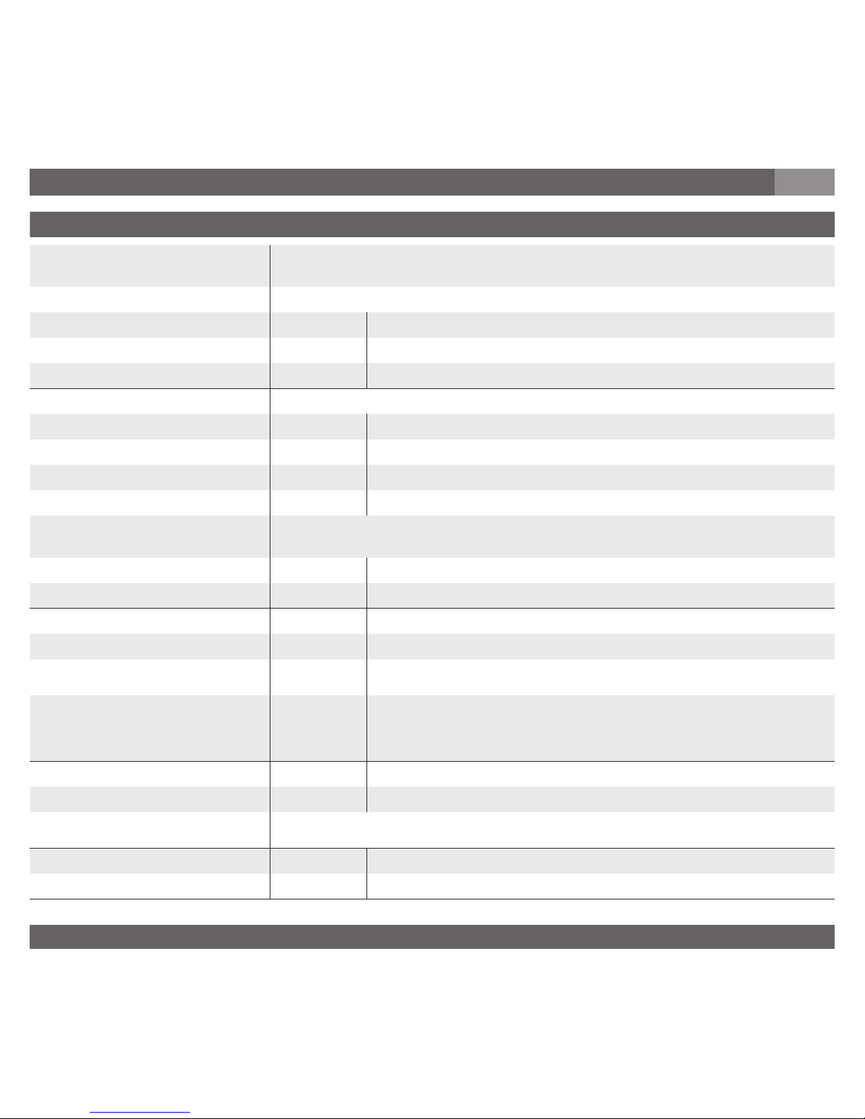
Technische Daten Typ PEX17 / PEX18
3)
Einschließlich Nichtlinearität, Hysterese, Nullpunkt- und Endwertabweichung
(entspricht Messabweichung nach IEC 61298-2).
Kalibriert bei senkrechter Einbaulage Druckanschluss nach unten.
Nichtlinearität % d. Spanne
≤
0,2 (BFSL) nach IEC 61298-2
Nichtwiederholbarkeit % d. Spanne
≤
0,1
Stabilität pro Jahr % d. Spanne
≤
0,2 (bei Referenzbedingungen)
Zulässige Temperaturbereiche
Messstoff
4)
°C -30 ... +100 °C {-40 ... +105 °C}
Umgebung
4)
°C -30 ... +100 °C {-40 ... +105 °C}
Lagerung
4)
°C -30 ... +105 °C {-40 ... +105 °C}
Kompensierter Temperaturbereich °C 0 ... +80
Temperaturkoeffizienten im
kompensierten Temperaturbereich
Mittlerer TK des Nullpunktes % d. Spanne
≤
0,2 / 10 K
Mittlerer TK der Spanne % d. Spanne
≤
0,2 / 10 K
CE- Kennzeichen
Druckgeräterichtlinie 97/23/EG
EMV-Richtlinie
2004/108/EWG, EN 61326 Emission (Gruppe 1, Klasse B) und
Störfestigkeit (industr. Bereich)
ATEX-Richtlinie für Geräte zur
bestimmungsgemäßen Ver-
wendung in explosionsgefähr deten Bereichen
94/9/EG
Ex -Schutz ATEX Kategorie
5)
2G
Zündschutzart Ex d II C T4, Ex d II C T5, Ex d II C T6
5)
Lesen Sie unbedingt die Einsatzbedingungen und sicherheitstechnischen Daten
in der EG Baumusterprüfbescheinigung nach (KEMA 10ATEX0099 X).
HF-Immunität V/m 10
BURST KV 4
7. Inbetriebnahme, Betrieb
D
Page 12
BD_BE 719 a
12 Betriebsanleitung/Operating instructions
Technische Daten Typ PEX17 / PEX18
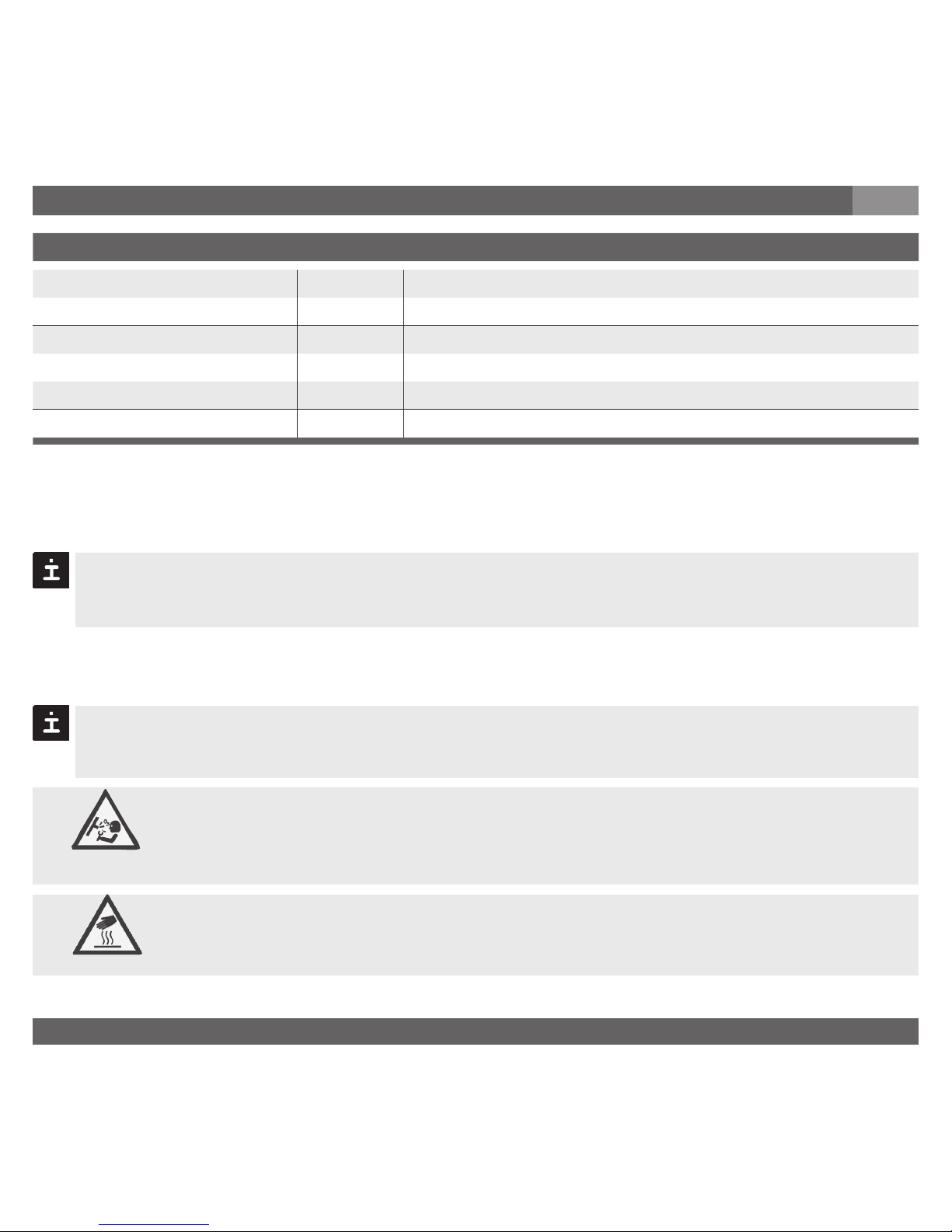
Schockbelastbarkeit g 1000 nach IEC 60068-2-27 (Schock mechanisch)
Vibrationsbelastbarkeit g 20 nach IEC 60068-2-6 (Vibration bei Resonanz)
Elektrische Schutzarten
Kurzschlussfestigkeit Sig+ gegen UB-
Verpolschutz UB+ gegen UB-
Masse kg Ca. 0,2
7. Inbetriebnahme, Betrieb
D
{ } Angaben in geschweiften Klammern beschreiben gegen Mehrpreis lieferbare Sonderheiten.
Beachten Sie bei der Auslegung Ihrer Anlage, dass die angegebenen Werte (z. B. Berstdruck, Überlastgrenze) in Abhängigkeit vom verwendeten Material, Gewinde und Dichtung gelten.
Funktionsprüfung
Öffnen Sie Anschlüsse nur im drucklosen Zustand!
Beachten Sie die Betriebsparameter gemäß Punkt 7„Technische Daten“.
Betreiben Sie das Druckmessgerät immer innerhalb des Überlastgrenzbe-
reichs!
Das Ausgangssignal muss sich dem anstehenden Druck proportional verhalten. Wenn
dies nicht so ist, kann das ein Hinweis auf eine Beschädigung der Membran sein. Lesen
Sie in diesem Fall in Kapitel 9 „Störbeseitigung“ nach.
Beachten Sie beim Berühren des Druckmessgerätes, dass die Oberflächen
der Gerätekomponenten während des Betriebes heiß werden können.
Warnung
Vorsicht
Page 13
BD_BE 719 a
13Betriebsanleitung/Operating instructions
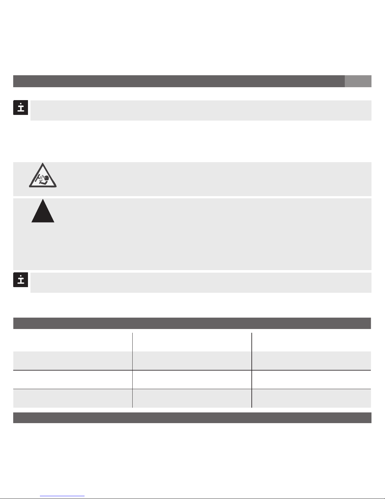
Störung Mögliche Ursache Maßnahme
Kein Ausgangssignal
Keine/Falsche Versorgungsspannung
oder Stromstoß
Versorgungsspannung gemäß Betriebsanleitung korrigieren *)
Leitungsbruch Durchgang überprüfen
Kein/Falsches Ausgangssignal
Verdrahtungsfehler (z. B. 2-Leiter als
3-Leiter verdrahtet)
Anschlussbelegung beachten (siehe
Typenschild / Betriebsanleitung)
Gleichbleibendes Ausgangssignal bei
Druckänderung
Mechanische Überlastung durch
Überdruck
Gerät austauschen; bei wiederholtem
Ausfall Rücksprache mit Hersteller *)
8. Wartung, Zubehör / 9. Störbeseitigung
D
8. Wartung, Zubehör
Zubehör: Entnehmen Sie bitte Zubehörangaben unserer aktuellen Standardpreisliste oder
setzen Sie sich mit unserem Vertriebsmitarbeiter in Verbindung.
9. Störbeseitigung
Öffnen Sie Anschlüsse nur im drucklosen Zustand!
tecsis Druckmessgeräte sind wartungsfrei.
Lassen Sie Reparaturen nur vom Hersteller durchführen.
Ergreifen Sie Vorsichtsmaßnahmen für Messstoffreste in ausgebauten
Druckmessgeräten. Messstoffreste können zur Gefährdung von Menschen,
Umwelt und Einrichtung führen!
Setzen Sie das Druckmessgerät außer Betrieb und schützen Sie es gegen
versehentliche Inbetriebnahme, wenn Sie Störungen nicht beseitigen
können.
Lassen Sie Reparaturen nur vom Hersteller durchführen.
Verwenden Sie keine spitzen bzw. harten Gegenstände zur Reinigung, denn die Membran
des Druckanschlusses darf nicht beschädigt werden.
Prüfen Sie bitte vorab, ob Druck ansteht (Ventile/Kugelhahn usw. offen) und ob Sie die richtige
Spannungsversorgung und die richtige Verdrahtungsart (2-Leiter/3-Leiter) gewählt haben.
Warnung
!
Warnung
Page 14
BD_BE 719 a
14 Betriebsanleitung/Operating instructions
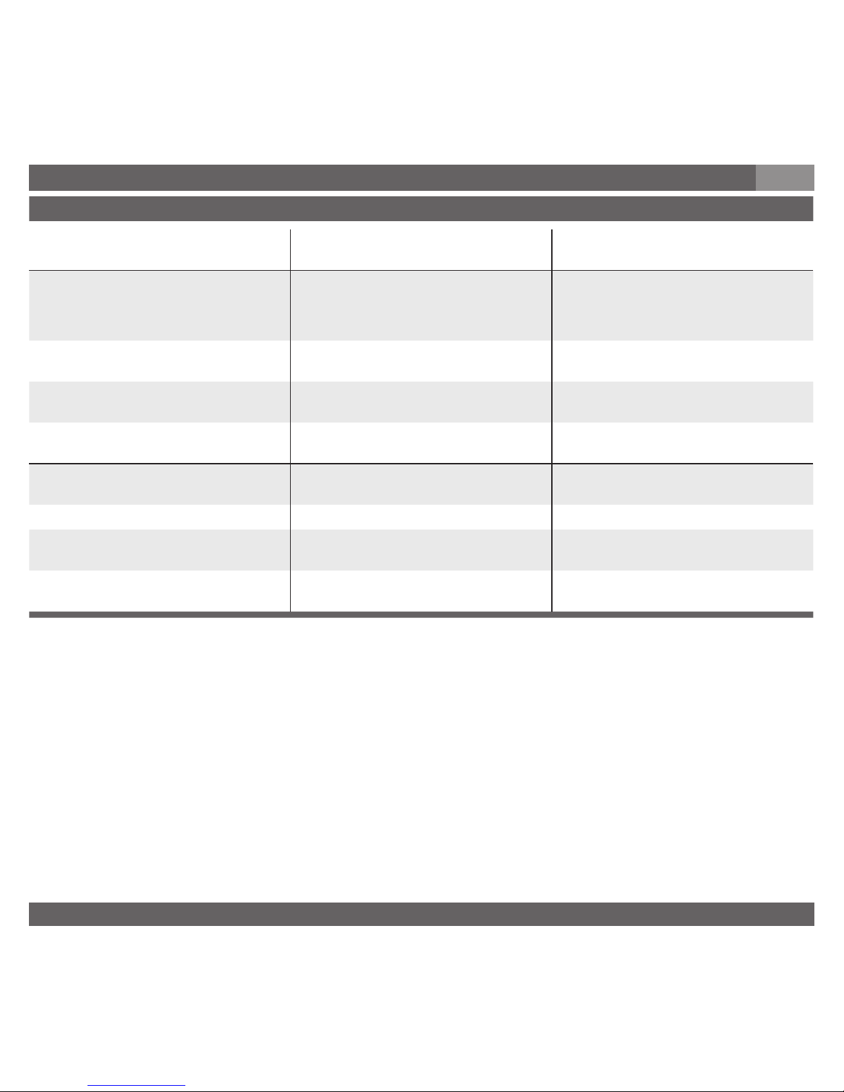
Störung Mögliche Ursache Maßnahme
Gleichbleibendes Ausgangssignal bei
Druckänderung
Falsche Versorgungsspannung oder
Stromstoß
Gerät austauschen
Signalspanne fällt/ab/zu klein
Membranbeschädigung, z. B. durch
Schläge, abrasives/agressives Medium;
Korrosion an Membran/Druckanschluss; Übertragungsmedium fehlt
Hersteller kontaktieren und Gerät
austauschen
Signalspanne zu klein Versorgungsspannung zu hoch/niedrig
Versorgungsspannung gemäß Betriebsanleitung korrigieren
Mechanische Überlastung durch
Überdruck
Gerät austauschen
Signalspanne fällt ab
Feuchtigkeit eingetreten (z. B. am
Kabelende)
Kabel korrekt montieren
Signalspanne schwankend
EMV-Störquellen in Umgebung, z. B.
Frequenzumrichter
Gerät abschirmen; Leitungsabschir-
mung; Störquelle entfernen
Gerät nicht geerdet Gerät erden
Stark schwankende Versorgungsspan-
nung
Versorgungsspannung stabilisieren;
entstören
Stark schwankender Druck des
Prozessmediums
Dämpfung; Beratung durch Hersteller
9. Störbeseitigung
D
Im unberechtigtem Reklamationsfall berechnen wir die Reklamationsbearbeitungs-Kosten.
*) Überprüfen Sie nach dem Justieren die korrekte Arbeitsweise des Systems. Besteht der Fehler weiterhin, senden Sie das Gerät zur
Reparatur ein (oder tauschen Sie das Gerät aus).
Wenn das Problem bestehen bleibt, setzen Sie sich mit unserem Vertriebsmitarbeiter in
Verbindung.
Prozess Material Zertifikat (Kontaminationserklärung im Servicefall)
Spülen bzw. säubern Sie ausgebaute Geräte vor der Rücksendung, um unsere Mitarbeiter und
die Umwelt vor Gefährdung durch anhaftende Messstoffreste zu schützen.
Eine Überprüfung ausgefallener Geräte kann nur sicher erfolgen, wenn das vollständig ausgefüllte Rücksendeformular vorliegt. Eine solche Erklärung beinhaltet alle Materialien, welche
mit dem Gerät in Berührung kamen, auch solche, die zu Testzwecken, zum Betrieb oder zur
Reinigung eingesetzt wurden. Das Rücksendeformular ist über unsere Internet-Adresse
(www.tecsis.de) verfügbar.
Page 15
BD_BE 719 a
15Betriebsanleitung/Operating instructions
10. Lagerung, Entsorgung / 11. EG-Konformitätserklärung
D
10. Lagerung, Entsorgung
Ergreifen Sie bei Lagerung und Entsorgung Vorsichtsmaßnahmen für Messstoffreste in ausgebauten Druckmessgeräten. Wir empfehlen eine geeignete und sorgfältige Reinigung. Messstoffreste können zur Gefährdung von
Menschen, Umwelt und Einrichtung führen!
Montieren Sie die Schutzkappe bei Lagerung des Druckmessgerätes, damit die Membran
nicht beschädigt wird (PEX18).
Entsorgen Sie Gerätekomponenten und Verpackungsmaterialien entsprechend den
einschlägigen landesspezifischen Abfallbehandlungs- und Entsorgungsvorschriften des
Anliefergebietes.
Lagerung
Entsorgung
11. EG-Konformitätserklärung
Technische Änderungen vorbehalten.
Warnung
!
Page 16
BD_BE 719 a
16 Betriebsanleitung/Operating instructions
12. EG-Baumusterprüfbescheinigung
D
Page 17
BD_BE 719 a
17Betriebsanleitung/Operating instructions
12. EG-Baumusterprüfbescheinigung
D
Page 18

BD_BE 719 a
18 Betriebsanleitung/Operating instructions
1. Important details for your information
GB
Use of the product in accordance with the intended use PEX17, PEX18:
Use the flameproof pressure sensor to transform the pressure into an electrical signal in
hazardous areas.
1. Important details for your information
Read these operating instructions before installing and starting the pressure sensor.
Keep the operating instructions in a place that is accessible to all users at any time.
The following installation and operating instructions have been compiled by us with great care
but it is not feasible to take all possible applications into consideration. These installation and
operation instructions should meet the needs of most pressure measurement applications.
If questions remain regarding a specific application, you can obtain further information:
Via our Internet address www.tecsis.de
The product data sheet is designated as DD719/DE719
Contact tecsis for additional technical support +49 69 5806-173
If the serial number on the product lable and/or the 2D code on the hexagon gets illegible
(e.g. by mechanical damage or repainting), the retraceability of the instrument is not possible
any more.
tecsis pressure sensors are carefully designed and manufactured using state-of-the-art
technology. Every component undergoes strict quality and environmental inspection before
assembly and each instrument is fully tested prior to shipment.
Certificate ATEX:
Pressure sensor for operation in hazardous areas in compliance with the respective certificate
(see EC-type examination certificate KEMA 10ATEX0099 X).
ATEX Approval ratings: Flameproof for II 2G Ex d II C T6 ... T1
Knowledge required
Install and start the pressure sensor only if you are familiar with the relevant regulations and
directives of your country and if you have the qualification required. You have to be acquainted
with the rules and regulations on hazardous areas, measurement and control technology and
electric circuits, since this pressure sensor is „electrical equipment“ as defined by EN 50178.
Depending on the operating conditions of your application you have to have the corresponding
knowledge, e.g. of aggressive media.
Page 19
BD_BE 719 a
19Betriebsanleitung/Operating instructions
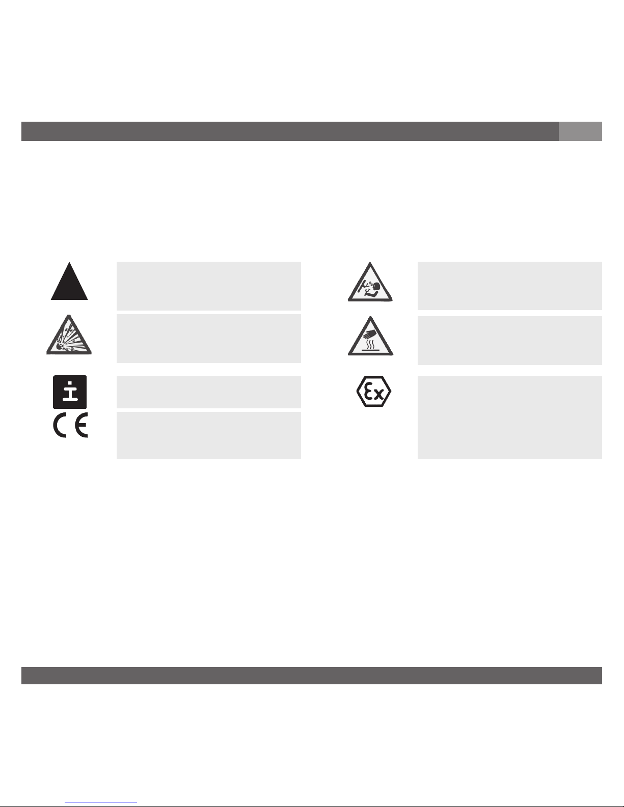
3. Signs, symbols and abbreviations
4. Function
PEX17: Pressure connection (flameproof) with internal diaphragm (standard version).
PEX18: Pressure connection with flush diaphragm (flameproof) for highly viscous or
solids entrained media which might clog the pressure port.
2-wire Two connection lines are intended for the voltage supply.
The supply current is the measurement signal.
3-wire Two connection lines are intended for the voltage supply.
One connection line is intended for the measurement signal.
ATEX European guideline for explosion protection (Atmosphäre=AT, Explosion=EX)
Potential danger of life or of
severe injuries.
Notice, important information, malfunction.
The product complies with
the applicable European
directives.
Instructions for hazardous
areas: Potential danger of
life or of severe injuries.
2. A quick overview for you / 3. Signs, symbols and abbreviations / 4. Function
GB
2. A quick overview for you
If you want to get a quick overview, read Chapters 3, 5, 7 and 10. There you will get some short
safety instructions and important information on your product and its starting. Read these
chapters in any case.
Potential danger of life or
of severe injuries due to
catapulting parts.
Potential danger of burns
due to hot surfaces.
The product complies with
the requirements of the
European directive 94/9/EC
(ATEX) on explosion protection.
!
Warning
Warning
Warning
Caution
Page 20

BD_BE 719 a
20 Betriebsanleitung/Operating instructions
4. Function / 5. For your safety
GB
Function
The pressure prevailing within the application is transformed into a standardised electrical
signal through the deflection of the diaphragm, which acts on the sensor element with the
power supply fed to the sensor. This electric signal changes in proportion to the pressure and
can be evaluated correspondingly.
5. For your safety
Select the appropriate pressure sensor with regard to scale range, perfor-
mance and specific measurement conditions prior to installing and starting
the instrument.
Observe the relevant national regulations (e.g.: EN 50178) and observe the
applicable standards and directives for special applications (e.g. with
dangerous media such as acetylene, flammable gases or liquids and toxic gases or liquids
and with refrigeration plants or compressors). If you do not observe the appropriate
regulations, serious injuries and/or damage can occur!
Open pressure connections only after the system is without pressure!
Please make sure that the pressure sensor is only used within the overload threshold limit
all the time!
Observe the ambient and working conditions outlined in section 7 „Technical data”.
Ensure that the pressure sensor is only operated in accordance with the provisions i.e. as
described in the following instructions.
Do not interfere with or change the pressure sensor in any other way than described in
these operating instructions.
Remove the pressure sensor from service and mark it to prevent it from being used again
accidentally, if it becomes damaged or unsafe for operation
Take precautions with regard to remaining media in removed pressure sensor. Remaining
media in the pressure port may be hazardous or toxic!
Have repairs performed by the manufacturer only.
!
Warning
Page 21
BD_BE 719 a
21Betriebsanleitung/Operating instructions
5. For your safety / 6. Packaging / 7. Starting, operation
GB
6. Packaging
Has everything been supplied?
Check the scope of supply:
Completely assembled pressure sensors; with flush version PEX18 including pre-
assembled sealings and protection cap.
Inspect the pressure sensor for possible damage during transportation. Should there
be any obvious damage, inform the transport company and tecsis without delay.
Keep the packaging, as it offers optimal protection during transportation (e.g. changing
installation location, shipment for repair).
Ensure that the pressure connection thread and the connection contacts will not be
damaged.
In order to protect the diaphragm, the pressure connection of the instrument PEX18 is provided
with a special protection cap.
Remove this protection cap only just before installing the pressure sensor in order to
prevent any damage to the diaphragm or the thread.
Keep the protection cap of the pressure connection thread and the diaphragm for later
storage or transport.
Mount the protection cap when removing and transporting the instrument.
7. Starting, operation
Required tools: wrench (flats 27), screw driver
Consider the details given in the EC-type examination certificate as well
as the respective country specific regulations for installation and operation
in hazardous areas (e.g.: IEC 60079-14). If you do not observe these stipulations, serious injuries and/or damage can occur.
Warning
Page 22
BD_BE 719 a
22 Betriebsanleitung/Operating instructions
7. Starting, operation
GB
Diaphragm test for your safety
It is necessary that before starting the pressure sensor you test the diaphragm, as this is a
safety-relevant component.
Pay attention to any liquid leaking out, for this points to a diaphragm damage.
Check the diaphragm visually for any damage (PEX18).
Use the pressure sensor only if the diaphragm is undamaged.
Use the pressure sensor only if it is in a faultless condition as far as the
safety-relevant features are concerned.
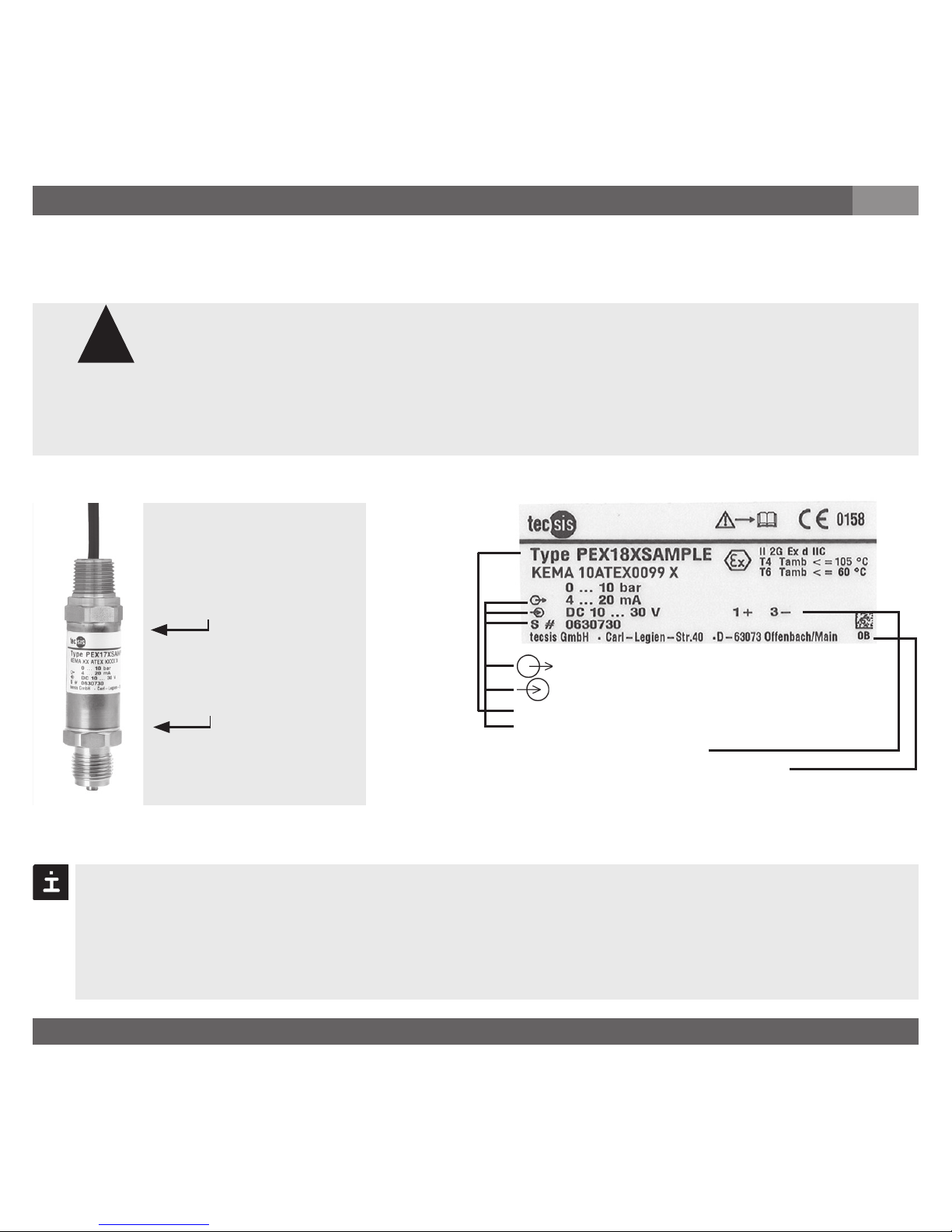
Signal
Power Supply
Product No.
Serial No.
PIN assignment
Coded manufacture date
P #
If there is no serial number on the product label, the number on the hexagon will apply.
Mechanical connection
Product label (example)
S #
Use to install the
sensor process
connection
max. 50 Nm
Use only to secure
sensor while
installing electrical
conduit
Remove the protection cap only just before installation and absolutely avoid any
damage to the diaphragm during installation as well (PEX18).
For Model PEX17 you have to provide for a sealing element; exceptions are instruments
with self-sealing threads (e.g. NPT thread).
For Model PEX18 the sealing ring is included in delivery.
!
Warning
Page 23
BD_BE 719 a
23Betriebsanleitung/Operating instructions
7. Starting, operation
GB
When mounting the instrument, ensure that the sealing faces of the instrument and
the measuring point are clean and undamaged.
Screw in or unscrew the instrument only via the flats using a suitable tool and the
prescribed torque. The appropriate torque depends on the dimension of the pressure
connection and on the sealing element used (form/material). Do not use the case as
working surface for screwing in or unscrewing the instrument.
When screwing the sensor in, ensure that the threads are not jammed.
Do not torque the process controller with a force greater than 36,9 foot pounds
(50 Nm).
Protect the diaphragm against any contact with abrasive substances and
pressure peaks and do not touch it with tools. If you damage the diaphragm,
no intrinsic safety can be guaranteed (ATEX)!
Do not use the pressure sensor out of the temperature range from
-40 ... +105 °C / -40 ... +221 °F. Out of this range there is no explosion
protection ensured.
Observe the permissible surface temperature applicable for this range according to the
defined temperature classes.
Electrical connection
Earth the housing through the process connection to protect the sensor from
electromagnetic fields and electrostatic discharge.
Ground the cable screen at one end, preferably in the safe, thus non-Ex, area
(EN 60079-14). For sensors with flying leads, the screen is connected to the
case. The simultaneous connection of case and cable screen to ground is only
permitted if ground loop problems between the screen connection (e.g. at the
power supply) and case can be excluded (see EN 60079-14).
Connect the instrument to a power supply that is equipped with a protective measure to
IEC 60364-4-41 (DN VDE 0100-410).
Warning
!
Warning
Warning
Page 24
BD_BE 719 a
24 Betriebsanleitung/Operating instructions
7. Starting, operation
GB
Attempting to remove the cable connection will damage the sensor and void
the factory warranty and approval.
The electrical connection to the sensor should be used as originally supplied.
It must not be bypassed or modified (with the exception of the cable length).
Improper assembly or alteration of the electrical connection will invalidate
the explosion protection class for which the sensor is certified.
Cover flying leads with fine wires by an end splice (cable preparation).
Installing with conduit use only threads NPT 1/2" according ANSI/ASME B1.20.1.
Screw them together with a minimum of 5 turns.
Clamp the free cable tail to a suitable certified clamp box or outside the hazardous area.
Operate the pressure sensor with a shielded cable and earth the shield at least on one
side of the cable, if the cable is longer than 30m (2-wire) or 3m (3- or 4-wire), or if it is
run outside of the building.
Ingress protection per IEC 60529
Please make sure that the ends of cables with flying leads do not allow any ingress of
moisture.
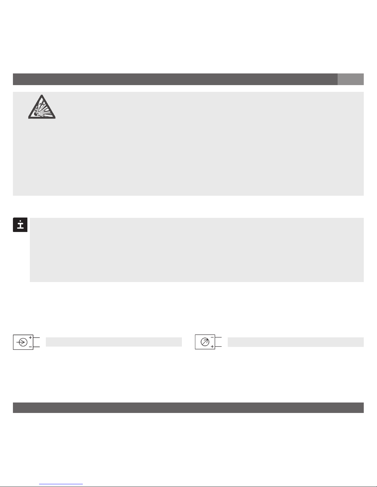
Load (e.g. display)
Power supply
UB+/Sig+ Positive supply / measurement connection
OV/Sig- Negative supply / measurement connection
Warning
Page 25
BD_BE 719 a
25Betriebsanleitung/Operating instructions
Specifications Model PEX17 / PEX18
Pressure ranges bar 0.4 0.6 1 1.6 2.5 4 6 10 16 25
Over pressure safety bar 2 4 5 10 10 17 35 35 80 50
Burst pressure bar 2.4 4.8 6 12 12 20.5 42 42 96 96
Pressure ranges bar 40 60 100 160 250 400 600 1000
1)
Over pressure safety bar 80 120 200 320 500 800 1200 1500
Burst pressure bar 400 550 800 1000 1200 1700
2)
2400
2)
3000
{Vacuum, gauge pressure, compound range, absolute pressure are available}
1)
Only Model PEX17 gültig.
2)
For model PEX18: the value specified in the table applies only when sealing is
realised with the sealing ring underneath the hex. Otherwise max. 1500 bar applies.
Materials
Wetted parts (other materials see tecsis diaphragm seal program)
» Model PEX17 Stainless steel (> 25 bar Elgiloy
®
)
» Model PEX18 Stainless steel
O-ring: NBR {FPM/FKM}
Case Stainless steel
Internal transmission fluid Synthetic oil (not for model PEX17 with pressure ranges > 25 bar)
Cable
with 2 m length
IP 67
Order code: DX
3-wire2-wire
7. Starting, operation
GB
red
red
black
black
brown
screen/case
screen/case
Page 26
BD_BE 719 a
26 Betriebsanleitung/Operating instructions
Specifications Model PEX17 / PEX18
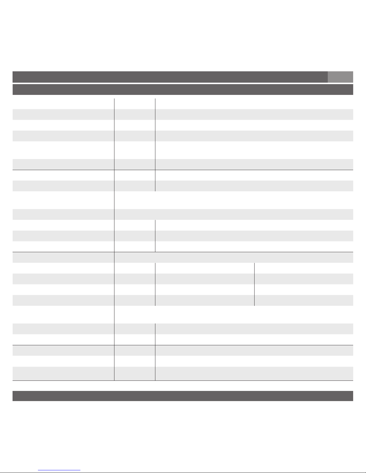
Power supply UB UB in VDC
10 < U
B ≤ 30 with signal output 4 ... 20 mA, 2-wire
6 < U
B ≤ 30 with signal output 1 ... 5 V, 3-wire
Signal output and R
A
in Ohm 4 ... 20 mA, 2-wire R
A
≤ (UB - 10 V) / 0.02 A
maximum ohmic load R
A 1 ... 5 V, 3-wire, R
A
> 10000
Response time (10 ... 90 %) ms
≤
1 (< 10 ms at medium temperatures below -30 °C for pressure
ranges up to 25 bar or with flush diaphragm)
Dielectric strength VDC 500
Accuracy % of span
≤
0.25 (BFSL)
≤
0.5
3)
3)
Including non-linearity, hysteresis, zero point and full scale error (corresponds to
error of measurement per IEC 61298-2).
Adjusted in vertical mounting position with lower pressure connection.
Non-linearity % of span
≤
0.2 (BFSL) according to IEC 61298-2
Non-repeatability % of span
≤
0.1
1-year stability % of span
≤
0.2 (at reference conditions)
Permissible temperature of
Medium
4)
-30 ... +100 °C {-40 ... +105 °C} -22 ... +212 °F {-40 ... +221 °F}
Ambience
4)
-30 ... +100 °C {-40 ... +105 °C} -22 ... +212 °F {-40 ... +221 °F}
Storage
4)
-30 ... +105 °C {-40 ... +105 °C} -22 ... +221 °F {-40 ... +221 °F}
Compensated temp range 0 ... +80 °C +32 ... +176 °F
Temperature coefficients within
compensated temp range
Mean TC of zero % of span
≤
0.2 / 10 K
Mean TC of range % of span
≤
0.2 / 10 K
CE- conformitiy
Pressure equipment directive 97/23/EC
EMC directive
2004/108/EWG, EN 61326 emission (Group 1, class B) and noise immunity (industr. area)
7. Starting, operation
GB
Page 27
BD_BE 719 a
27Betriebsanleitung/Operating instructions
Specifications Model PEX17 / PEX18
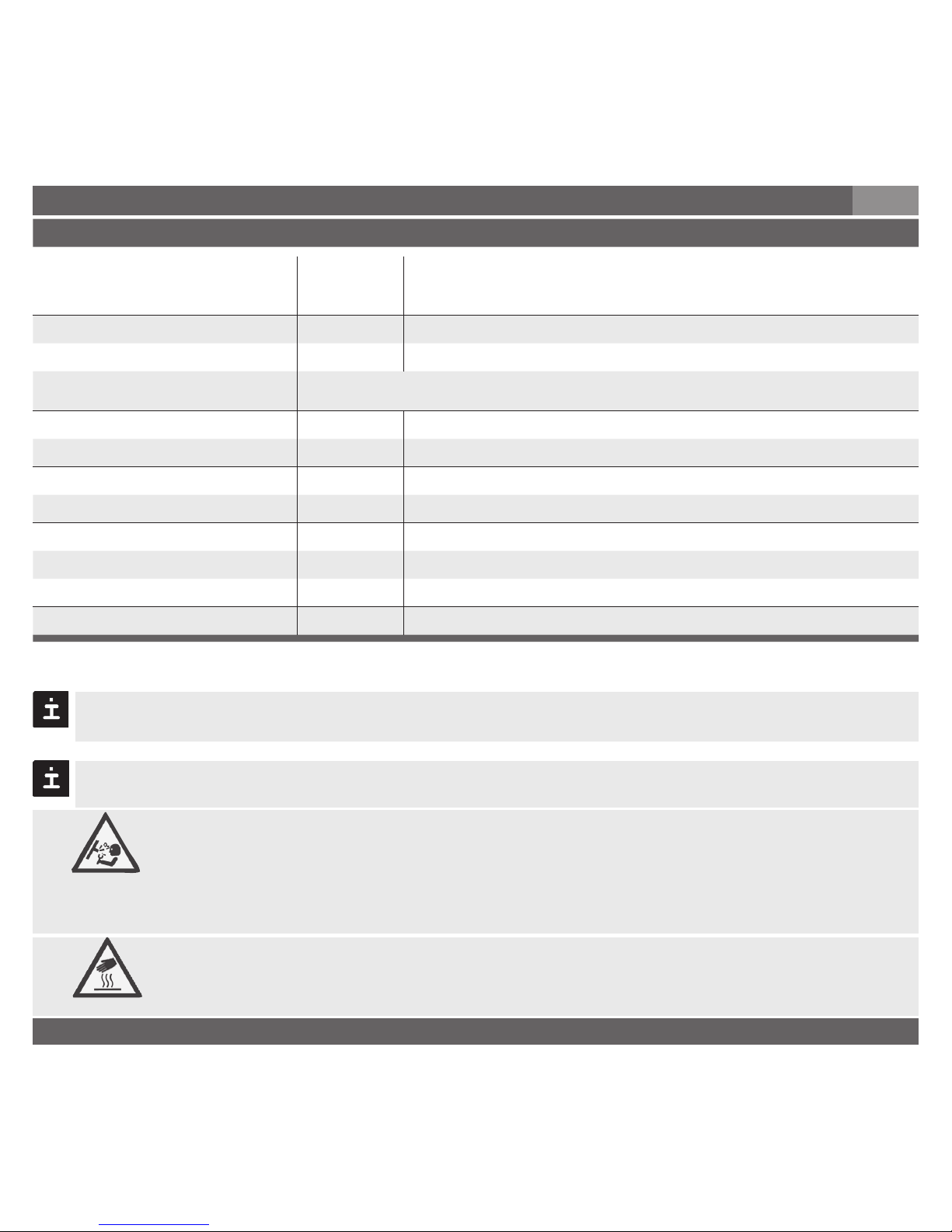
Directive ATEX of equipment
intended for use in potentially
explosive atmospheres
94/9/EC
Ex-protection ATEX Category
5)
2G
Ignition protection type Ex d II C T4, Ex d II C T5, Ex d II C T6
5)
Read the operating conditions and safety-relevant data in the EC-type
examination certificate in any case (KEMA 10ATEX0099 X)
HF-immunity V/m 10
BURST kV 4
Shock resistance g 1000 according to IEC 60068-2-27 (mechanical shock)
Vibration resistance g 20 according to IEC 60068-2-6 (vibration under resonance)
Wiring protection
Short-circuit proofness Sig+ towards UB-
Reverse polarity protection UB+ towards UB-
Weight kg Approx. 0.2
7. Starting, operation
GB
When designing your plant, take into account that the stated values (e.g.burst pressure,
over pressure safety) apply depending on the material, thread and sealing element used.
{ } Items in curved brackets are optional extras for additional price.
Functional test
Open pressure connections only after the system is without pressure!
Observe the ambient and working conditions outlined in section 7
„Technical data.
Please make sure that the pressure sensor is only used within the over load
threshold limit at all times!
When touching the pressure sensor, keep in mind that the surfaces of the
instrument components might get hot during operation.
The output signal must be proportional to the pressure. If not, this might point to a
damage of the diaphragm. In that case refer to chapter 9 „Troubleshooting“.
Warning
Caution
Page 28
BD_BE 719 a
28 Betriebsanleitung/Operating instructions
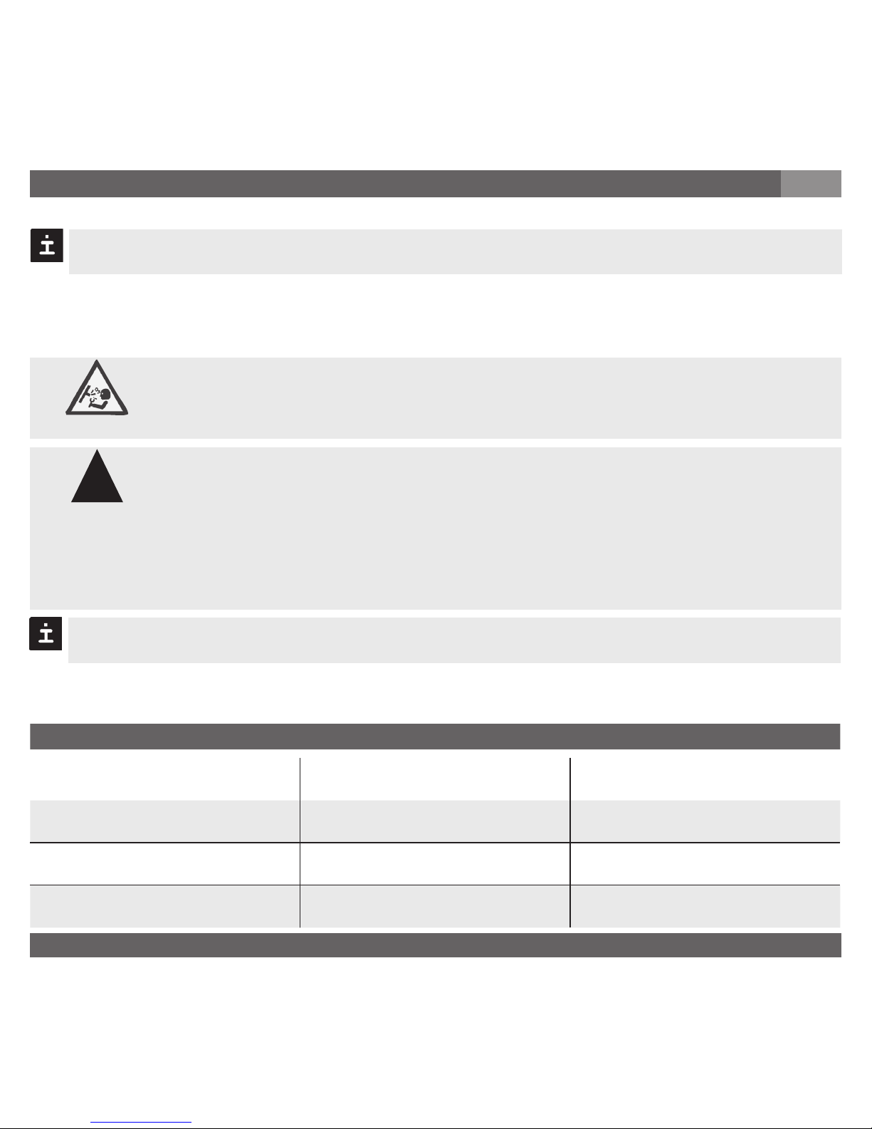
Failure Possible cause Procedure
No output signal
No/incorrect voltage supply or current
spike
Mechanical overload through overpressure
Cable break Check connections and cable
No/False output signal
Incorrectly wired (e.g. Connected as
2-wire instead of 3-wire system)
Follow pin assignment (see Instrument
Label / Operating Instructions)
Output signal unchanged after change
in pressure
Mechanical overload through overpressure
Replace instrument; if failure reoccurs,
consult the manufacturer *)
8. Maintenance, accessories / 9. Trouble shooting
GB
8. Maintenance, accessories
Accessories: For details about the accessories, please refer to tecsis‘s price list or or contact
our sales department.
tecsis pressure sensors require no maintenance.
Have repairs performed by the manufacturer only.
9. Trouble shooting
Open pressure connections only after the system is without pressure!
Do not insert any pointed or hard objects into the pressure port for cleaning to prevent
damage to the diaphragm of the pressure connection.
Take precautions with regard to remaining media in removed pressure
sensors. Remaining media in the pressure port may be hazardous or
toxic!
Remove the pressure sensor from service and mark it to prevent it from
being used again accidentally, if it becomes damaged or unsafe for operation.
Have repairs performed by the manufacturer only.
Please verify in advance if pressure is being applied (valves/ ball valve etc. open) and if the right
voltage supply and the right type of wiring (2-wire/ 3-wire) has been chosen?
Warning
!
Warning
Page 29
BD_BE 719 a
29Betriebsanleitung/Operating instructions
Failure Possible cause Procedure
Output signal unchanged after change
in pressure
Wrong supply voltage or current spike Replace instrument
Signal span dropping off/too small
Diaphragm is damaged, e.g. through
impact, abrasive/agressive media;
corrosion of diaphragm/pressure
connector; transmission fluid missing.
Contact the manufacturer and replace
the instrument
Signal span too small Power supply too high/too low
Correct the power supply in line with
the Operating Instructions
Mechanical overload through overpressure
Replace instrument
Signal span drops off Moisture present (e.g. at the cable tail) Install the cable correctly
Signal span erratic
Electromagnetic interference source in
the vicinity, e.g. inverter drive
Shield the device; shield the cables;
remove the interference source.
9. Trouble shooting
GB
In case of unjustified reclamation we charge the reclamation handling expenses.
*) Make sure that after the setting the unit is working properly. In case the error continues to exist send in the instrument for reparation (or
replace the unit).
If the problem persists, contact our sales department.
USA, Canada
If the problem continues, contact tecsis or an authorized agent for assistance. If the pressure
sensor must be returned obtain an RMA (return material authorization) number and shipping
instructions from the place of purchase. Be sure to include detailed information about the
problem. Pressure sensors received by tecsis without a valid RMA number will not be accepted.
Process material certificate (Contamination declaration for returned goods)
Purge / clean dismounted instruments before returning them in order to protect our employees
and the environment from any hazard caused by adherent remaining media.
Service of instruments can only take place safely when a Product Return Form has been
submitted and fully filled-in. This Return Form contains information on all materials with which
the instrument has come into contact, either through installation, test purposes, or cleaning.
You can find the Product Return Form on our internet site (www.tecsis.de).
Page 30
BD_BE 719 a
30 Betriebsanleitung/Operating instructions
10. Storage, disposal / 11. EC declaration of conformity
GB
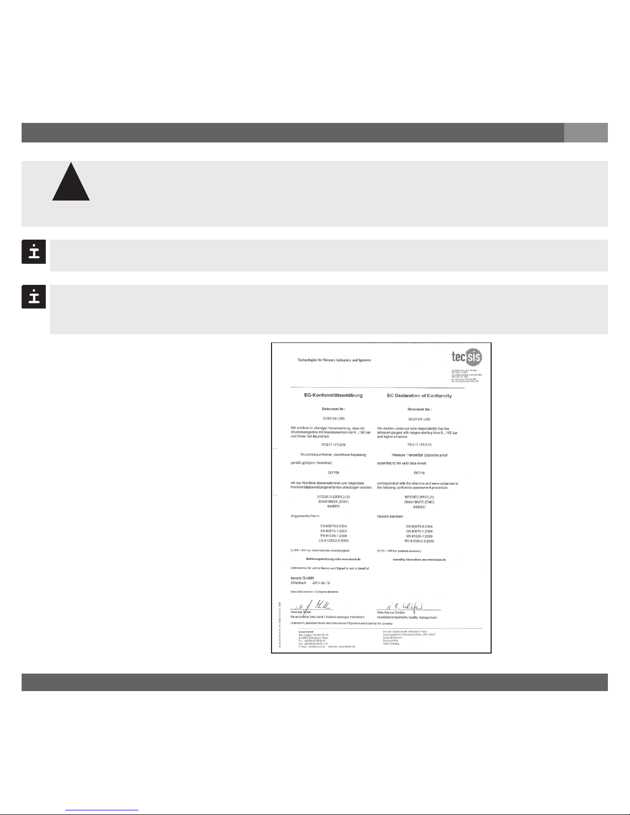
11. EC declaration of conformity
10. Storage, disposal
When storing or disposing of the pressure sensor, take precautions with
regard to remaining media in removed pressure sensors. We recommend
cleaning the sensor properly and carefully. Remaining media in the pressure
port may be hazardous or toxic!
Mount the protection cap when storing the pressure sensor in order to prevent any
damage to the diaphragm (PEX18).
Dispose of instrument components and packaging materials in accordance with the
respective waste treatment and disposal regulations of the region or country to which
the instrument is supplied.
Storage
Disposal
tecsis reserves the right to alter these technical specifications.
!
Warning
Page 31
BD_BE 719 a
31Betriebsanleitung/Operating instructions
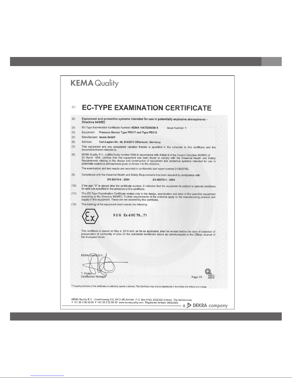
12. EC-Type Examination Certificate
GB
12. EC-Type Examination Certificate
(KEMA 10ATEX0099 X)
Page 32
BD_BE 719 a
32 Betriebsanleitung/Operating instructions
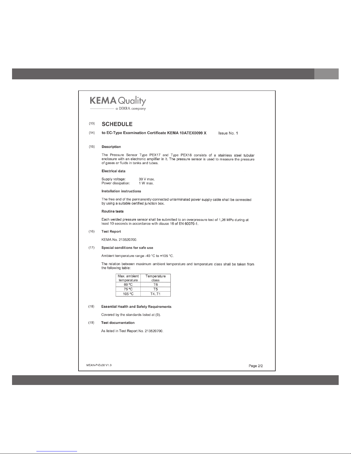
12. EC-Type Examination Certificate
GB
 Loading...