


D
GB
Betriebsanleitung
Operating instructions
Differenzdruckmessgerät mit Magnetkolben und
mit Magnetkolben und Trennmembrane Baureihe P2600
Differential pressure gauge with magnetic piston and
with magnetic piston and separation diaphragm Model P2600
tecsis GmbH
Carl-Legien-Straße 40-44
63073 Offenbach . Germany
Tel.: +49 (0)69/5806 0
Fax:
+49 (0)69/5806 7788
E-Mail: info@tecsis.de
www.tecsis.de
mit Magnetkolben/
with magnetic Piston
mit Magnetkolben,
Trennmembrane
und Reed-Kontakt/
with magnetic Piston,
separation Diaphragm
and Reed-Contact
BD_BE 450 e 06/2011
ADPR1X414002 SN-Nr. 2165384

2
BD_BE 450 e 06/2011
D
GB
Betriebsanleitung Baureihe P2600 Page 3-12
Operating instructions model P2600 Seite 13-22
© 2011 tecsis GmbH
All rights reserved. / Alle Rechte vorbehalten.
tecsis
®
is a registered trademark in various countries.
tecsis
®
ist eine geschützte Marke in verschiedenen Ländern.
Vor Beginn aller Arbeiten Betriebsanleitung lesen!
Zum späteren Gebrauch aufbewahren!
Prior to starting any work, read the operating instructions!
Keep for later use!

3
Betriebsanleitung
BD_BE 450 e 06/2011
D
1. Allgemeines 3
2. Sicherheit 4
3. Technische Daten 7
4. Aufbau und Funktion 7
5. Optionen und Zubehör 8
6. Transport, Verpackung und Lagerung 9
7. Montage, Inbetriebnahme, Betrieb 9
8. Wartung und Reinigung 12
9. Reparatur 12
10. Demontage und Entsorgung 13
Inhalt
Inhalt

Betriebsanleitung
4
BD_BE 450 e 06/2011
D
1. Allgemeines
1. Allgemeines
Das in der Betriebsanleitung beschriebene Differenzdruckmessgerät wird nach
den neuesten Erkenntnissen konstruiert und gefertigt.
Alle Komponenten unterliegen während der Fertigung strengen Qualitäts- und
Umweltkriterien. Unsere Managementsysteme sind nach ISO 9001 zertifiziert.
Diese Betriebsanleitung gibt wichtige Hinweise zum Umgang mit dem Differenzdruckmessgerät. Voraussetzung für sicheres Arbeiten ist die Einhaltung aller
angegebenen Sicherheitshinweise und Handlungsanweisungen.
Die für den Einsatzbereich des Differenzdruckmessgerätes geltenden örtlichen
Unfallverhütungsvorschriften und allgemeinen Sicherheitsbestimmungen
einhalten.
Die Betriebsanleitung ist Produktbestandteil und muss in unmittelbarer Nähe
des Druckmessgerätes für das Fachpersonal jederzeit zugänglich aufbewahrt
werden.
Das Fachpersonal muss die Betriebsanleitung vor Beginn aller Arbeiten sorgfältig durchgelesen und verstanden haben.
Die Haftung des Herstellers erlischt bei Schäden durch bestimmungswidrige
Verwendung, Nichtbeachten dieser Betriebsanleitung, Einsatz ungenügend
qualifizierten Fachpersonals sowie eigenmächtiger Veränderung am Differenzdruckmessgerät.
Es gelten die allgemeinen Geschäftsbedingungen in den Verkaufsunterlagen.
Technische Änderungen vorbehalten.
Weitere Informationen:
- Internet-Adresse: www.tecsis.de
- zugehöriges Datenblatt: DD470/DE470
Symbolerklärung
WARNUNG!
… weist auf eine möglicherweise gefährliche Situation hin, die zum
Tod oder zu schweren Verletzungen führen kann, wenn sie nicht
gemieden wird.
Information
… hebt nützliche Tipps und Empfehlungen sowie Informationen für
einen effizienten und störungsfreien Betrieb hervor.

5
Betriebsanleitung
BD_BE 450 e 06/2011
D
2. Sicherheit
2. Sicherheit
WARNUNG!
Vor Montage, Inbetriebnahme und Betrieb sicherstellen, dass das
richtige Druckmessgerät hinsichtlich Messbereich, Ausführung und
spezifischen Messbedingungen ausgewählt wurde.
Auswahl- und Einbauempfehlungen für Druckmessgeräte nach
EN 837-2 beachten.
Verträglichkeit der druckbelasteten Werkstoffe mit dem Messstoff
prüfen!
Die Belastungsgrenzen sind einzuhalten, um die Messgenauigkeit
und die Lebensdauer zu gewährleisten.
Bei Nichtbeachten können schwere Körperverletzungen und/oder
Sachschäden auftreten.
Weitere wichtige Sicherheitshinweise befinden sich in den
einzelnen Kapiteln dieser Betriebsanleitung.
2.1 Bestimmungsgemäße Verwendung
Diese Differenzdruckmessgeräte dienen zur Überwachung von Differenzdrücken
bei industriellen Anwendungen.
Das Differenzdruckmessgerät ist ausschließlich für den hier beschriebenen
bestimmungsgemäßen Verwendungszweck konzipiert und konstruiert und darf
nur dementsprechend verwendet werden.
Ansprüche jeglicher Art aufgrund von nicht bestimmungsgemäßer Verwendung
sind ausgeschlossen.
2.2 Personalqualifikation
WARNUNG!
Verletzungsgefahr bei unzureichender Qualifikation!
Unsachgemäßer Umgang kann zu erheblichen Personen- und
Sachschäden führen.
Die in dieser Betriebsanleitung beschriebenen Tätigkeiten nur durch Fachpersonal nachfolgend beschriebener Qualifikation durchführen lassen.

Herstellungsdatum
Betriebsanleitung
6
BD_BE 450 e 06/2011
D
Fachpersonal
Das Fachpersonal ist aufgrund seiner fachlichen Ausbildung, seiner Kenntnisse
der Mess- und Regelungstechnik und seiner Erfahrungen sowie Kenntnis der
landesspezifischen Vorschriften, geltenden Normen und Richtlinien in der Lage,
die beschriebenen Arbeiten auszuführen und mögliche Gefahren selbstständig
zu erkennen.
2.3 Besondere Gefahren
WARNUNG!
Messstoffreste in ausgebauten Druckmessgeräten können zur
Gefährdung von Personen, Umwelt und Einrichtung führen.
Ausreichende Vorsichtsmaßnahmen ergreifen.
2.5 Beschilderung / Sicherheitskennzeichnungen
Typenschild (bei Option Reed-Kontakt)
Symbolerklärung
Vor Montage und Inbetriebnahme des Druckmessgerätes unbedingt
die Betriebsanleitung lesen!
CE, Communauté Européenne
Geräte mit dieser Kennzeichnung stimmen überein mit den
zutreffenden europäischen Richtlinien.
2. Sicherheit
Model P2600 Cont 6.3
MAX. LASTDATEN / CONTACT RATING
Pmax AC/DC 3 W
Umax AC/DC 30 V
Imax AC/DC 0,2 A
Prod-No: P2600 12/2010
UL-Nr: E103299
CSA-Nr: LR57810
left
right

7
Betriebsanleitung
BD_BE 450 e 06/2011
D
3. Technische Daten
3. Technische Daten / 4. Aufbau und Funktion
Technische Daten Baureihe P2600
Reed-Kontakt
ohne mit
Nenngröße 80
Anzeigegenauigkeit ± 3 % vom Skalenendwert bei
ansteigendem Differenzdruck
± 5 % vom Skalenendwert bei
ansteigendem Differenzdruck
Anzeigebereiche 0 … 400 mbar bis 0 … 10 bar 0 … 160 mbar bis 0 … 2,5 bar
Max. Betriebsdruck
(statischer Druck)
wahlweise 100, 250 oder
400 bar
100 bar
(Anzeigebereiche 0 ... 160 mbar
und 0 ... 250 mbar: 50 bar)
Überlastbarkeit ein-, beid- und wechselseitig bis zum maximalen Betriebsdruck
(Ausnahme bei Geräten mit Reed-Kontakt, Anzeigebereiche
0 ... 160 mbar und 0 ... 250 mbar: Überlastbarkeit bis 50 bar)
Schutzart lP 54 (EN 60529 / lEC 529)
Messkammer mit
Druckanschluss
(messstoffberührt)
CrNi-Stahl 1.4571, 2 x G ¼ Innengewinde, rechts und links
seitlich, gegenüberliegend (EN 837-1 /7.3)
Weitere technische Daten siehe tecsis Datenblatt DD470/DE470 und
Bestellunterlagen.
4. Aufbau und Funktion
Beschreibung
In den
- und - Messstoffkammern herrschen die Drücke p1 und p2,
getrennt durch den druckbeaufschlagten Magnetkolben (bzw. Magnetkolben
und Trennmembrane).
Die Druckdifferenz verursacht eine axiale Bewegung (Messweg) des Kolbens, der
sich gegen die Messbereichsfeder abstützt.
Der sich daraus ergebende Messweg wird von einem auf dem Instrumentenzeiger befindlichen Ringmagneten abgegriffen und zur Anzeige gebracht. Dieser
konstruktive Aufbau verbindet den Vorteil einer vollständigen Trennung von
Messsystem und Anzeige und verhindert jegliche Leckage nach außen.
Der Volumenstrom von der
- zur - Messstoffkammer bei Typ P2600 ist
aufgrund des konstruktiven Aufbaus minimal und in Regelanwendungen nicht
störend.
Bei der Option mit Trennmembrane tritt kein Volumenstrom von der -
zur
- Messstoffkammer auf.
Bewährte Anwendungen/Einsatzgebiete sind Gas- und Luftversorgung und deren
Aufbereitung, in denen keine magnetischen Partikel enthalten sind.
C
D
B
B
A
C
D
Betriebsanleitung
8
BD_BE 450 e 06/2011
D
Befinden sich Schwebekörper im Prozess sollte der Typ P2600 mit Reed-Kontakt
eingesetzt werden.
Lieferumfang
Lieferumfang mit dem Lieferschein abgleichen.
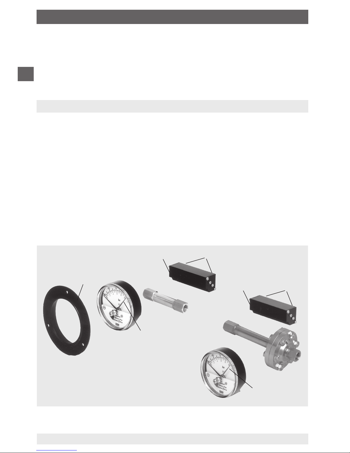
5. Optionen und Zubehör
5.1 Befestigungsrand
Nach Bedarf vor Ort nachrüstbar.
Ausrichten des Frontringes (A) über eingeprägte Nocken zu am Gehäuseumfang
befindlichen Nuten. Frontring auf Gehäuse bis zum Einschnappen aufschieben.
5.2 Minimum- bzw. Maximum-Schleppzeiger (siehe Darstellungen)
Schleppzeiger (B) dient zur Überwachung und Kontrolle des minimalen bzw.
maximalen aufgetretenen Differenzdruckes.
5.3 Reed-Kontakt Typ 6.3 und 6.3.3 (siehe Darstellungen)
Nach Bedarf vor Ort nachrüst- und einstellbar.
Befestigung erfolgt über zwei im Reedgehäuse (C) integrierte Schrauben (D) am
Anzeigegehäuse mit dem dazugehörigen Innengewinde.
5. Optionen und Zubehör

9
Betriebsanleitung
BD_BE 450 e 06/2011
D
7. Montage, Inbetriebnahme, Betrieb
Mechanischer Anschluss
Die Montage des Differenzdruckmessgerätes erfolgt in Anlehnung an die Einbauempfehlungen für Druckmessgeräte nach EN 837-2 /7.
Montage des Prozessanschlusses nach angebrachten Symbolen
und
hoher Druck, niedriger Druck
Bei Montage mittels Schraubenschlüssel SW 17 an den Anschlussstücken
gegenhalten (Einschrauben ohne gegenhalten kann zur Lockerung des
Messsystems führen).
Maximale zulässige Messstoff-/Umgebungstemperatur darf nicht überschritten werden
Messleitungen vor der Gerätemontage gründlich durch Abklopfen und Ausblasen oder Durchspülen reinigen
Messgeräte sollen erschütterungsfrei montiert und betrieben werden
Messgeräte sollen vor Verschmutzung und starken Temperaturschwankungen
geschützt sein
Um Fremdkörper im Messsystem und somit eine Beschädigung desselben zu
vermeiden, ist das Druckmessgerät oberhalb des Entnahmestutzens anzubringen.
Bei stark schwebekörperhaltigen Messstoffen ist vor der
-
Messstoffkammer ein
Feinfilter vorzusehen.
6. Transport, Verpackung und Lagerung
6.1 Transport
Druckmessgerät auf eventuell vorhandene Transportschäden untersuchen.
Offensichtliche Schäden unverzüglich mitteilen.
6.2 Verpackung
Verpackung erst unmittelbar vor der Montage entfernen.
Die Verpackung aufbewahren, denn diese bietet bei einem Transport einen
optimalen Schutz (z. B. wechselnder Einbauort, Reparatursendung).
6.3 Lagerung
Zulässige Bedingungen am Lagerort
Lagertemperatur: -20 ... +70°C (optional: -40 … +70°C)
6. Transport, Verpackung und Lagerung / 7. Inbetriebnahme ...
Betriebsanleitung
10
BD_BE 450 e 06/2011
D
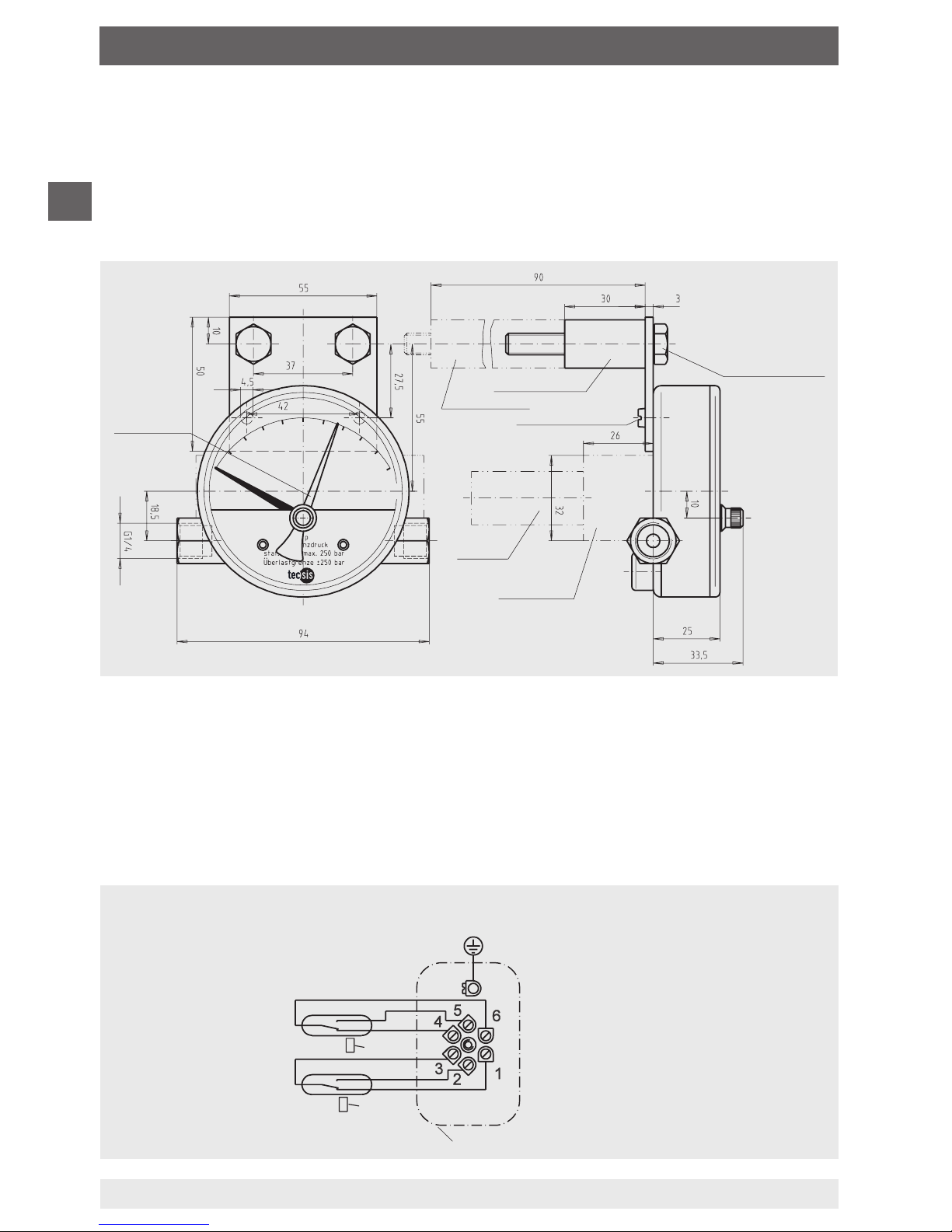
7. Inbetriebnahme, Betrieb
Sechskantschraube
M8 x 50 (M8 x 100)
ohne Reedkontakt
mit Reedkontakt
Schlitzschraube M4 x 10
Reedgehäuse
Schleppzeiger
Stecker
Elektrischer Anschluss
(bei Geräten mit elektrischen Zusatzeinrichtungen)
Der elektrische Anschluss des Druckmessgerätes wird über Kabeldose und
Kabel hergestellt. Die genauen Anschlussbelegungen können dem nachfolgenden
Anschlussschema entnommen werden. Zusätzlich sind Anschlussbelegung und
erforderliche Hilfsenergie auf dem Typenschild des Reedgehäuses vermerkt.
Elektrisches Anschlussschema
Reed-Kontakt Typ 6.3 und 6.3.3
(Wechsler)
In den Geräten sind
keine Überstrom-Schutzeinrichtungen eingebaut.
Falls Schutzeinrichtungen
gefordert werden, sind
diese extern vorzusehen.
Kabeldose
2. Kontakt
1. Kontakt
6. 3
6.3. 3
Ist die Leitung zum Druckmessgerät für eine erschütterungsfreie Anbringung
nicht stabil genug, so ist die Befestigung über entsprechende Befestigungselemente für Wandmontage oder ggf. über eine Kapillare vorzunehmen.
Montage an Wand (siehe Zeichnung)
Anbringung/Befestigung mittels Messgerätehalter

11
Betriebsanleitung
BD_BE 450 e 06/2011
D
7. Inbetriebnahme, Betrieb
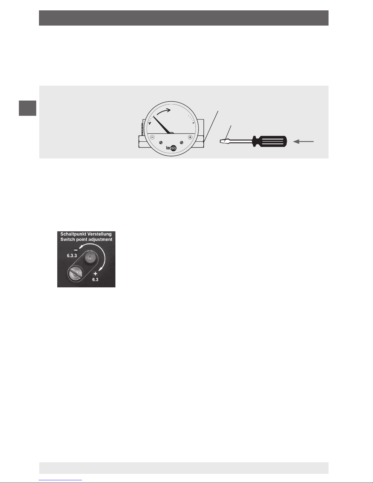
Schaltpunkteinstellung
Vorzugsweise erfolgt die Schaltpunkteinstellung vor dem Einbau des
Messgerätes. Der erforderliche Prüfweg wird manuell (z. B. mit Hilfe eines
nicht magnetischen Schraubendrehers) erzeugt.
Manuelle Prüfwegerzeugung
Plusmessstoffkammer
antimagnetisch
Die Schaltpunkteinstellung kann auch im druckbeaufschlagten Zustand nach
Einbau erfolgen. Bei Angabe der Sollwerte werden werkseitig die Schaltpunkte
eingestellt.
Die Verstellung des Schaltpunktes erfolgt durch Drehen der Kontakt-Einstellschrauben an der Reed-Gehäuseaußenseite.
Drehrichtung links:
Schaltpunkt lässt sich in Richtung
Messbereichsanfang verschieben
Drehrichtung rechts:
Schaltpunkt lässt sich in Richtung
Messbereichs
ende verschieben
Nullpunktprüfung
Im Allgemeinen erfolgt die Überprüfung und Einstellung des Nullpunktes im
drucklosen Zustand. Für die Nullpunktkorrektur des Druckmessgerätes ist
die Systembefestigungslasche an der Gehäuserückseite leicht zu lösen. Der
Nullpunkt lässt sich nun durch Verschieben des Messsystems nach rechts
oder links nachjustieren. Anschließend ist das Messsystem wieder mittels
Befestigungslasche (maximales Anzugsmoment der Befestigungsschraube
2,5 Nm) zu fixieren.
Betriebsanleitung
12
BD_BE 450 e 06/2011
D
8. Wartung und Reinigung
8.1 Wartung
Die Geräte sind wartungsfrei.
Bei sachgemäßer Behandlung und Bedienung zeichnen sich die Kolben-Diffe-
renzdruckmessgeräte durch eine hohe Lebensdauer aus.
Die Messgenauigkeit des Druckmessgerätes sollte durch regelmäßige
Prüfungen sichergestellt werden.
Reparaturen sind ausschließlich vom Hersteller oder entsprechend qualifiziertem Fachpersonal durchzuführen.
8.2 Reinigung
Messstoffreste in ausgebauten Druckmessgeräten können zur Gefährdung von
Menschen, Umwelt und Einrichtungen führen. Ausreichende Vorsichtsmaßnahmen sind zu ergreifen.
VORSICHT!
■
Das Druckmessgerät mit einem feuchten Tuch reinigen.
■
Ausgebautes Druckmessgerät vor der Rücksendung spülen
bzw. säubern, um Personen und Umwelt vor Gefährdung
durch anhaftende Messstoffreste zu schützen.
9. Reparatur
Gefährliche Arbeitsstoffe
Wir bitten bei Anlieferung von Reparaturgeräten und Retouren, die mit gefährlichen Arbeitsstoffen im Messstoffraum und/oder an den Oberflächen in Berührung gekommen sind, vorher um Reinigung und möglichst genaue Stoffangabe
des gefährlichen Mediums. Bei Reinigung durch tecsis ist die genaue Angabe
des Messstoffes bzw. dessen Zusammensetzung und Verarbeitungshinweise incl.
Angabe der Schutzmaßnahmen zum sicheren Umgang für unser Annahme- und
Wartungspersonal zwingend erforderlich.
ACHTUNG!
Bei von tecsis nicht zu entsorgenden Arbeitsstoffen erfolgt eine
Rücksendung an den Kunden.
Kennzeichnung und Verpackung gemäß Gefahrstoff-Verordnung.
8. Wartung und Reinigung / 9. Reparatur

13
Betriebsanleitung
BD_BE 450 e 06/2011
D
9. Demontage und Entsorgung
10. Demontage und Entsorgung
WARNUNG!
Messstoffreste in ausgebauten Druckmessgeräten können
zur Gefährdung von Personen, Umwelt und Einrichtung führen.
Ausreichende Vorsichtsmaßnahmen ergreifen.
10.1 Demontage
Druckmessgerät nur im drucklosen Zustand demontieren!
10.2 Entsorgung
Durch falsche Entsorgung können Gefahren für die Umwelt entstehen.
Gerätekomponenten und Verpackungsmaterialien entsprechend den landesspezifischen Abfallbehandlungs- und Entsorgungsvorschriften umweltgerecht
entsorgen.
Entsorgung durch tecsis gemäß Auftrag. Bei Sendung der zu entsorgenden
Geräte Passus „Gefährliche Arbeitsstoffe“ beachten (siehe Punkt 9).
Entsorgungsempfehlung bei kundenseitiger Entsorgung:
- bei Gefahrenstoffen im/am Gerät zuerst Gefahrstoff unberührte Teile abbauen
- Gefahrenstoff unberührte Teile Schrott, je nach Material
- Gefahrenstoff berührte Teile Sondermüll
- Anbauteile Kunststoff Schrott, Kunststoff
- Anbauteile metallisch Schrott je nach Material
- Elektronikbauteile Sondermüll, geeignete Entsorgung
Informationen zu den verwendeten Werkstoffen und Komponenten können
dem Gerät zugehörigen Typenblatt entnommen werden (falls nicht vorhanden
anfordern). Bei ausgeführten Sonderheiten abweichend vom Inhalt des genannten Typenblattes sind diese der tecsis-Auftragsbestätigung bei Bestellung zu
entnehmen.
Technische Änderungen vorbehalten.

14
BD_BE 450 e 06/2011
Operating instructions
GB
1. General information 15
2. Safety 16
3. Specifications 18
4. Design and function 18
5. Options and accessories 19
6. Transport, packaging and storage 20
7. Installation, commissioning, operation 20
8. Maintenance and cleaning 23
9. Repairs 23
10. Dismounting and disposal 24
Content
Contents

Operating instructions
15
BD_BE 450 e 06/2011
GB
1. General information
1. General information
The differential pressure gauge described in the operating instructions has been
designed and manufactured using state-of-the-art technology.
All components are subject to stringent quality and environmental criteria during
production. Our management system is certified to ISO 9001.
These operating instructions contain important information on handling the
differential pressure gauge. Working safely requires that all safety instructions
and work instructions are observed.
Observe the relevant local accident prevention regulations and general safety
regulations for the differential pressure gauge's range of use.
The operating instructions are part of the product and must be kept in the
immediate vicinity of the pressure gauge and readily accessible to skilled
personnel at any time.
Skilled personnel must have carefully read and understood the operating
instructions prior to beginning any work.
The manufacturer's liability is void in the case of any damage caused by using
the product contrary to its intended use, non-compliance with these operating
instructions, assignment of insufficiently qualified skilled personnel or
unauthorised modifications to the differential pressure gauge.
The general terms and conditions contained in the sales documentation shall
apply.
Subject to technical modifications.
Further information:
- Internet address: www.tecsis.de
- Relevant data sheet: DD470/DE470
Explanation of symbols
WARNING!
... indicates a potentially dangerous situation that can result in
serious injury or death, if not avoided.
Information
… points out useful tips, recommendations and information for
efficient and trouble-free operation.

16
BD_BE 450 e 06/2011
Operating instructions
GB
2. Safety
2. Safety
WARNING!
Before installation, commissioning and operation, ensure that
the appropriate pressure gauge has been selected in terms of
measuring range, design and specific measuring conditions.
Observe the selection and installation recommendations for
pressure gauges in accordance with EN 837-2.
Check the compatibility with the medium of the materials
subjected to pressure!
In order to guarantee the measuring accuracy and long-term
stability specified, the corresponding load limits must be
observed.
Non-observance can result in serious injury and/or damage to
the equipment.
Further important safety instructions can be found in the individual chapters of these operating instructions.
2.1 Intended use
These differential pressure gauges are used for monitoring differential pressures
in industrial applications.
The differential pressure gauge has been designed and built solely for the
intended use described here and may only be used accordingly.
The manufacturer shall not be liable for claims of any type based on operation
contrary to the intended use.
2.2 Personnel qualification
WARNING!
Risk of injury should qualification be insufficient!
Improper handling can result in considerable injury and damage
to equipment.
The activities described in these operating instructions may
only be carried out by skilled personnel who have the qualifications described below.

Operating instructions
17
BD_BE 450 e 06/2011
GB
Date of manufacture
2. Safety
Skilled personnel
Skilled personnel are understood to be personnel who, based on their technical
training, knowledge of measurement and control technology and on their
experience and knowledge of country-specific regulations, current standards
and directives, are capable of carrying out the work described and independently
recognising potential hazards.
2.3 Special hazards
WARNING!
Residual media in dismounted pressure gauges can result in a
risk to people, the environment and the system. Take sufficient
precautionary measures.
2.5 Labelling / safety marks
Product label (with option reed contact)
Explanation of symbols
Before mounting and commissioning the pressure gauge, ensure
you read the operating instructions!
CE, Communauté Européenne
Instruments bearing this mark comply with the relevant European directives.
Model P2600 Cont 6.3
MAX. LASTDATEN / CONTACT RATING
Pmax AC/DC 3 W
Umax AC/DC 30 V
Imax AC/DC 0.2 A
Prod-No: P2600 12/2010
UL-Nr: E103299
CSA-Nr: LR57810
left
right

18
BD_BE 450 e 06/2011
Operating instructions
GB
3. Specifications
3. Specifications / 4. Design and function
Specifications Model P2600
Nominal size 80
Reed contact without with
Accuracy class ± 3 % of full scale value with
increasing differential pressure
± 5 % of full scale value with
increasing differential pressure
Scale ranges 0 … 400 mbar to 0 … 10 bar 0 … 160 mbar to 0 … 2.5 bar
Max. working
pressure
(static pressure)
optionally 100, 250 or 400 bar 100 bar
(scale ranges 0 ... 160 mbar and
0 ... 250 mbar: 50 bar)
Overpressure safety either side to maximum working pressure
(exception for pressure gauges with Reed contact,
scale ranges 0 ... 160 mbar and 0 ... 250 mbar:
Overpressure safety up to 50 bar)
Ingress protection lP 54 (EN 60529 / lEC 529)
Measuring chamber
with pressure
connection (wetted)
Stainless steel 1.4571, 2 x G ¼ female, on the right and left side,
in-line (EN 837-1 /7.3)
For further specifications see tecsis data sheet DD470/DE470 and the order
documentation.
4. Design and function
Description
Pressures p
1
and p2 are given in the and measuring chambers, separated
by the magnetic piston under pressure (or magnetic piston and separating
diaphragm.
The difference in pressure causes an axial movement (deflection) of the piston
supported by the compression spring.
The deflection resulting from this is taken up by a ring magnet found on the
instrument pointer and appropriately displayed. This design combines the
advantages of complete separation of the measuring system and the indication
while eliminating any leakage to the exterior.
For model P2600 the volume flow from the
measuring chamber to the
measuring chamber is minimised by the constructive design and will not interfere with standard processes. For model with option the separation diaphragm
prevents any flow volume from the
to the measuring chamber.
These instruments are mainly intended for gas/air supply and preparation applications where no magnetic particles are involved.
Operating instructions
19
BD_BE 450 e 06/2011
GB
C
D
B
B
A
C
D
In processes with floating particles model P2600 with Reed contact should be
used.
Scope of delivery
Cross-check the scope of delivery with the delivery note.
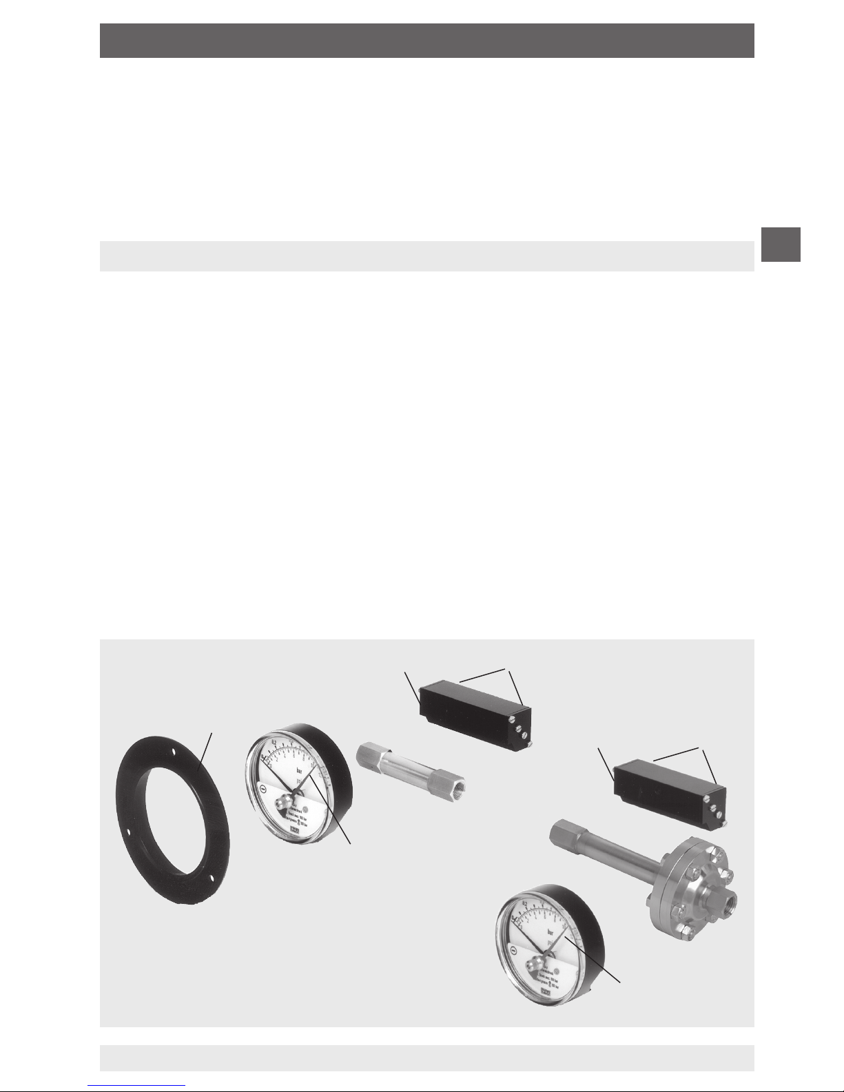
5. Options and accessories
5.1 Mounting flange
May be retrofitted on site as required.
Alignment of the front bezel (A) by means of the stamped cams to the grooves
found on the case circumference. Push front bezel on the case until it snaps into
position.
5.2 Minimum or maximum drag pointer (see illustrations)
The drag pointer (B) serves to monitor and control the miniumum or maximum
occurring differential pressure.
5.3 Reed contact model 6.3 and 6.3.3 (see illustrations)
May be retrofitted and adjusted on site as required.
Fastening is by means of two screws (D) integrated in the reed case (C) on the
display case with the pertinent female thread.
5. Options and accessories

20
BD_BE 450 e 06/2011
Operating instructions
GB
7. Installation, commissioning, operation
Mechanical connection
The installation of the differential pressure gauge is made following the installation
recommendations for pressure gauges in accordance with EN 837-2 /7.
Mounting of the process connection according to affixed symbols
and
high pressure, low pressure
Hold against the connection pieces in the case of installation by means of
17 mm screw spanner (installation without holding against the connection
pieces may cause thet measuring system to get loose).
The maximum permissible medium/ambient temperature must not be exceeded.
Prior to the installation of the pressure gauge, clean the measuring lines
thoroughly by tapping and blowing or rinsing.
Mount and operate the measuring instruments free from vibration.
Protect measuring instruments from contamination and high temperature
changes.
To avoid foreign matter in the measuring system and the resulting damage to the
system, the pressure gauge must be mounted above the connector.
A fine filter is to be provided in the
- measuring media chamber in the case of
measuring media containing a high level of floating particles.
6. Transport, packaging and storage
6.1 Transport
Check pressure gauge for any damage that may have been caused by transport.
Obvious damage must be reported immediately.
6.2 Packaging
Do not remove packaging until just before mounting.
Keep the packaging as it will provide optimum protection during transport (e.g.
change in installation site, sending for repair).
6.3 Storage
Permissible conditions at the place of storage:
Storage temperature: -20 ... +70 °C (optional: -40 … +70 °C)
6. Transport, packaging and storage / 7. Installation

Operating instructions
21
BD_BE 450 e 06/2011
GB
7. Installation, commissioning, operation
Hexagon bolt
M8 x 50 (M8 x 100)
without reed contact
with reed contact
Slotted screw M4 x 10
Reed case
Drag pointer
Plug
Electrical connection
(for instruments with electrical accessories)
Electrical connection of the pressure gauge is by means of terminal box and
cable. Precise wiring schemes can be seen in the following connection diagram.
In addition both the pin assignment and the required power supply are stated on
the product label of the reed case.
Electrical connection diagram
Reed contact model 6.3 and 6.3.3
(change-over contact)
The instruments do not
provide for incorporated
overcurrent protectors. If
overcurrent protectors are
requested, these have to
be provided for externally.
Terminal box
2nd contact
1nd contact
6. 3
6.3. 3
If the line to the gauge is not rigid enough for a vibration-free installation, the
gauge should be mounted by means of appropriate fastening elements for wall
mounting, or, if necessary, with a capillary.
Wall mounting (see drawing)
Installation / fastening by means of mounting brackets
22
BD_BE 450 e 06/2011
Operating instructions
GB
7. Commissioning, operation
Switch point adjustment
Preference should be given to setting the switch point before installing the
measuring instrument. The necessary test path is generated manually (e.g. by
means of an antimagnetic screwdriver).
Manual test path generation
Plus media chamber
antimagnetic
The switch point can also be set in a pressurised condition after installation. The
switch points are set at the factory when the set points are given.
The switch point is adjusted by turning the contact adjustment screws on the
outside of the reed case.
Anticlockwise rotation:
Switch point can be moved in the direction of the
start of the measuring range
Clockwise rotation:
Switch point can be moved in the direction of the
end of the measuring range
Zero point check
In general, the zero point should only be checked and adjusted at zero pressure.
The system fastening lug on the back of the case can be easily slackened off for
zero point correction of the pressure gauge. Now the zero point can be readjusted
by moving the measuring system to the right or left. After this has been done the
measuring system is to be secured again by means of the fastening lug (max.
tightening torque of the mounting screw 2.5 Nm).

Operating instructions
23
BD_BE 450 e 06/2011
GB
8. Maintenance and cleaning
8.1 Maintenance
The instruments are maintenance-free.
The differential pressure gauges with piston offer long service life provided they
are handled and operated properly.
Checks should be carried out on a regular basis to ensure the measuring
accuracy of the pressure gauge.
Repairs must only be carried out by the manufacturer or appropriately qualified
skilled personnel.
8.2 Cleaning
Remains of measuring media in dismantled pressure gauges can be a hazard to
people, the environment and facilities. Adequate measures are to be taken as a
precaution.
CAUTION!
■
Clean the pressure gauge with a moist cloth.
■
Wash or clean the dismounted pressure gauge before returning
it, in order to protect persons and the environment from exposure to residual media.
9. Repairs
Hazardous working materials
We would ask for instruments returned or sent in for repair, which have
hazardous materials in the media areas and/or have surface contact with
hazardous materials, to be cleaned beforehand and an as accurate as possible
description of the hazardous medium. It is absolutely essential to provide exact
details of the media or its composition and processing instructions including
safety measures to be taken to safeguard the ambient for our acceptance
and maintenance personnel.
IMPORTANT!
Working materials not to be disposed off by tecsis are returned
to the customer.
Marking and packaging in accordance with hazardous materials
ordinance.
8. Maintenance and cleaning / 9. Repairs
24
BD_BE 450 e 06/2011
Operating instructions
GB
10. Dismounting and disposal
WARNING!
Residual media in dismounted pressure gauges can result in a
risk to persons, the environment and equipment. Take sufficient
precautionary measures.
9.1 Dismounting
Only disconnect the pressure gauge once the system has been depressurised!
9.2 Disposal
Incorrect disposal can put the environment at risk.
Dispose of instrument components and packaging materials in an
environmentally compatible way and in accordance with the country-specific
waste disposal regulations.
Disposal by tecsis in accordance with order. Please note the paragraph on
“Hazardous Working Materials” when sending instruments for disposal
(see point 9).
Disposal recommendations in the case of disposal by customers:
- First dismantle parts not coming into contact with the hazardous material
in the case or hazardous materials in and on the instrument
- Parts not in contact with hazardous material scrap according to material
- Parts coming into contact with hazardous material special waste
- Mounted parts, plastic scrap, plastic
- Mounted parts, metal scrap according to material
- Electronic components special waste, suitable disposal
Information on the materials and components used can be seen from the type
sheet for the instrument (if not available please ask for copy). In the case of
special features deviating from the contents of the mentioned type sheet these
are to be taken from the tecsis confirmation of order when order is placed.
Technical alteration rights observed.
10. Dismounting and disposal

25
BD_BE 450 e 06/2011

26
BD_BE 450 e 06/2011

27
BD_BE 450 e 06/2011

BD_BE 450 e 06/2011
tecsis GmbH
Carl-Legien-Straße 40-44
63073 Offenbach . Germany
Tel.: +49 (0)69/5806 0
Fax:
+49 (0)69/5806 7788
E-Mail: info@tecsis.de
www.tecsis.de
 Loading...