

Page 1
Kraft Druck Temperatur Schalten Service
Force Pressure Temperature Switch Service
Betriebsanleitung
Operating manua l
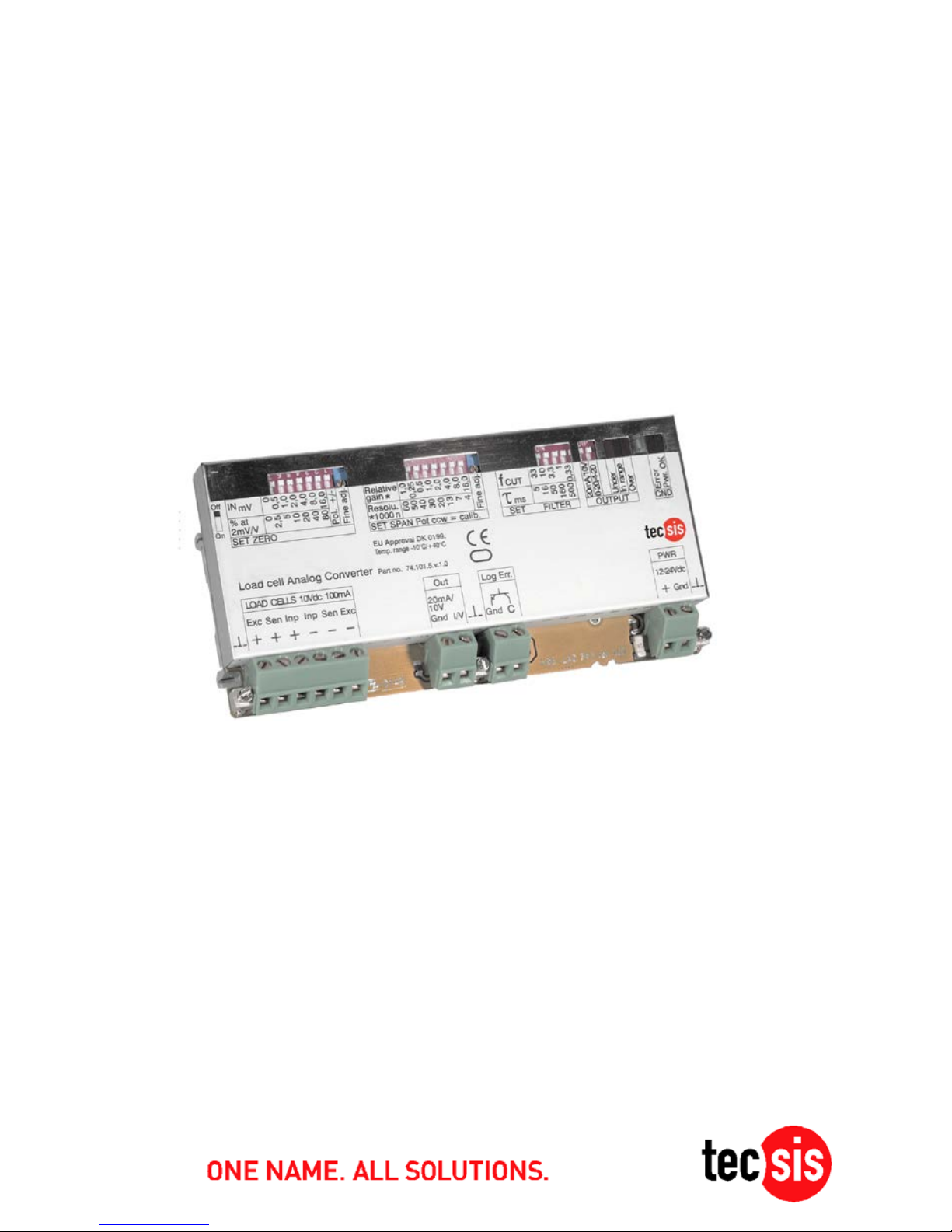
EZE11
Universal – DMS Verstärk er modul
Universal load cell analog converter
BD_BE 945 b
Page 2

Betriebsanleitung/ Operating manual
EZE11
2 BD_BE 945 b www.tecsis.de
Inhalt
1 KALIBRIERUNG DES ANALOG-AUSGANGSSIGNALS ........................... 3
1.1 EINBAU DES MODULS .................................................................... 3
1.2 EINSTELLELEMENTE...................................................................... 3
2 MIKROSCHALTEREINSTELLUNG ............................................................ 4
2.1 TIEFPASSFILTER ........................................................................... 4
2.2 NULLPUNKT .................................................................................. 4
2.3 VERSTÄRKUNG ............................................................................. 4
2.4 WAAGE ABGLEICHEN .................................................................... 5
2.5 WAAGE NULLSETZEN .................................................................... 5
2.6 WAAGE MAX.-LAST, WÄGEBEREICH KALIBRIEREN ......................... 5
2.7 WAAGE BETRIEBSBEREIT .............................................................. 5
3 SPEZIFIKATIONEN ..................................................................................... 6
1
CALIBRATING THE ANALOGUE OUTPUT SIGNAL................................. 8
1.1 INSTALLING THE MODULE .............................................................. 8
1.2 ADJUSTMENT ELEMENTS ............................................................... 8
2 MICRO SWITCH ADJUSTMENTS .............................................................. 9
2.1 LOW PASS FILTER ......................................................................... 9
2.2 ZERO SETTING .............................................................................. 9
2.3 SPAN ( GAIN) SETTING ................................................................... 9
2.4 CALIBRATING THE SCALE ............................................................ 10
2.5 ZEROING THE SCALE ................................................................... 10
2.6 CALIBRATING THE MAX. SCALE LOAD, WEIGHING RANGE ............... 10
2.7 SCALE READY FOR OPERATION .................................................... 10
3 TECHNICAL SPECIFICATIONS ............................................................... 11
D
GB
Page 3
Betriebsanleitung/ Operating manual
EZE11
www.tecsis.de BD_BE 945 b 3
1 Kalibrierung des Analog-Ausgangssignals
1.1 Einbau des Moduls
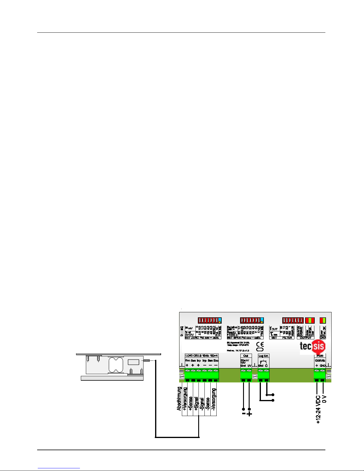
Das DMS-Modul ist in einem k undenseitigen Schaltsc hrank entspr echend
den VDE-Vorschriften einzubauen und gemäß dem Anschlussbild zu
verkabeln. Alle Anschlüsse sind auf dem Modul-Gehäuse aufgedruckt.
Das Verstärker-Modul arbeitet mit 6-Leiter-Technik, werden Wägezellen
mit 4-Leiter-Technik angeschlossen, so müssen die Anschlüsse
(+)Versorgung/Exc. mit (+)Sense und (-) Versorgung/Exc. mit (-)Sense
verbunden (gebrückt) werden.
1.2 Einstellelemente
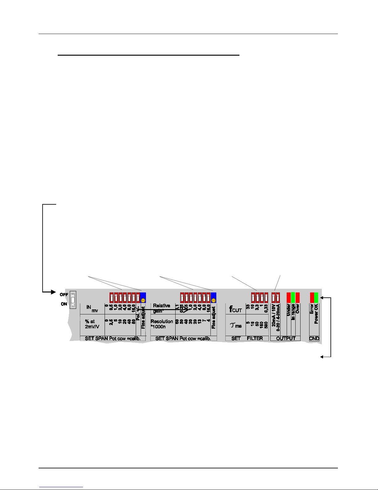
Alle Mikroschalter und Potentiometer sind auf der Gehäuseoberseite gut
zugänglich angeordnet.
Bei Auslieferung befinden sich alle DIP-Schalter in der „OFF“Position.
(entspricht ca. 0mV/V…2mV/V = 0/4…20 mA bzw. 0…10 V)
*ACHTUNG: Bei Nutzung des 0-10Volt-Ausgangs muss zusätzlich der
Wahlschal ter “0-20/4-20mA” auf 0-20mA eingestellt werden!
DIP-Schalter und Po tentiometer zur Ei n
-
stellung des
Nullpunktes
DIP-Schalter und Po tentiometer zur Ei n
-
stellung der
Verstärkung
DIP-Schalter zur Tiefpassfilter
-Einstellung
0,33 bis 33 Hz
DIP-Schalter zur Wahl
des Analogausgangs
-
signals 0
-20 mA oder
4
-20 mA oder 0-10V*
Anzeige-Funktion der LED`s:
Power OK
= Stromvers orgung i st da
Error
= Fehlermeldung (in Kombination m i t Open Collector Ausgang)
Under range
= Eingangs signal zu klein (negativ)
In range
= Eingangssignal ok
Over range
= Eingangssignal zu groß
Page 4

Betriebsanleitung/ Operating manual
EZE11
4 BD_BE 945 b www.tecsis.de
2 Mikroschaltereinstellung
2.1 Tiefpassfilter
Durch die vier DIP-Schalter k ann die Filterung in einem Bereich von 0,33
Hz bis 33 Hz eingestellt werden (s. Tabelle). In der Grundeinstellung ist
der Tiefpassf ilter auf 33 Hz eingestellt, alle DIP-Schalter s tehen in “OFF”Stellung. Damit ist praktisch keine Filterung mehr vorhanden, die
Einschwingzeit (99,98% des Signals) des EZE11 ist damit auf etwa 40 ms
minimiert. Die Einschwingzeit bei einer Filterung von 0,33 Hz beträgt dann
ca. 4000 ms.
DIP Schalter ON
keiner
1 2 3
4
Zeitkonstante
ms 5 16
50
160
500
Einschwingzeit ( 99,98%)
ms
40
130
400
1300
4000
Grenzfrequenz
Hz
33
10
3,3
1,0
0,33
2.2 Nullpunkt
Die ersten sechs Mikroschalter ermöglichen die Nullpunktverschiebung in
0,5mV-Schritten in einem Bereich von 0 bis 31,5mV (s. T abelle). Mit dem
siebten DIP-Schalter wird die Polarität der Nullpunktverschiebung gewählt,
entweder postiv oder negativ. Soll beispielsweise eine Vorlast
tariert/kompensiert werden ist die Einstellung “-/ negativ” zu wählen. Der
Analogausgang lässt sich bis zu max. +/-80% der Nennlast verschieben.
Die Feineinstellung erfolgt über das 20-gang-Wendelpotentiometer
DIP Schalter ON
none
1 2 3 4 5 6 all
Pol
Pot
relativ zu 20mV
% 0 2,5 5 10
20
40
80
157
+/ -
35
Input bei Null V
out
mV 0 0,5 1 2 4 8
16
31,5
+ /-
0,6
2.3 Verstärkung
Die 7 DIP-Schalter und das Trimmpotentiometer ermöglichen die stufenlose Einstellung der Vers tärkung von Eingangss ignalen von 1mV bis 32m V
zu einem Ausgangssignal von 0...10V bzw. 0/4...20mA (s. Tabelle)
DIP Schalter ON
none
1 2 3 4 5 6 7
all
pot
rel. Verst- Faktor
x 1 0,25
0,5 1 2 4 8
16
33
0,3
Input für 10 V
out
mV
32
30
28
24
16 8 4 2 1
Page 5
Betriebsanleitung/ Operating manual
EZE11
www.tecsis.de BD_BE 945 b 5
2.4 Waage abgleichen
Ein digitales Messgerät (Multimeter) , nach Möglichkeit 5-stellig oder mehr,
wird am Ausgang des Moduls (wahlweise der Strom- oder Spannungsausgang) angeschlossen. Das Multimeter sollte im Strombereich
mindestens eine Auflösung von 0,01 mA haben um wenigstens mit einer
Genauigkeit von 0,05% kalibrieren zu können.
2.5 Waage nullsetzen
Das Nullsetzen der Waage mit niedriger oder hoher Vorlast erfolgt nun
grob mit den Mikroschaltern und anschliessend fein mit dem Potentiometer.
Die W aage wird also komplett entlastet und dann das Ausgangss ignal mit
Hilfe der Mikroschalter und dem Potentiometer auf einen exakten
Ausgangsstrom von z.B. 4,00 mA eingestellt.
2.6 Waage Max.-Last, Wägebereich kalibrieren
Die Waage mit Nenngewicht (Voll-Last) belasten und anschliessend die
Verstärkung über die Mik roschalter (grob) und das Potentiometer (f ein) so
einstellen bis exakt 20,00 mA am Multimeter angezeigt werden. Diese
Prozedur (Punkt 5 und 6) sollte mehrmals wiederholt werden. Soll bspw.
nur ein Teilbereich des Waagen-Nennwertes eingesetzt werden, so kann
die Verstärkung durch Änderung der Mikroschalter entsprechend grob
verändert werden. W erden z. B. nur 50% des N ennwertes benötigt und hat
die angeschlossene Wägezelle einen Nennkennwert von 2mV/V, so stellt
man die Mikroschalter der Verstärkung entsprechend auf 1mV/V (i.e 10mV)
ein (s. Tabelle).
2.7 Waage betriebsbereit
Die Waage ist nun betriebsbereit.
Typ. Plattform 600 x 600 mm
Analogausgang:
wahlweise
0/4...20mA oder
0...10V*
Logikausgang:
Open Collector,
normal geschlossen,
öffnet bei einem
Fehler am EZE11
*ACHTUNG:
Bei Nutzung des 0
-10Volt-
Ausgangs muss zusätzlich
der
Wahlschalter “0
-20/4-20mA” auf
0
-20mA eingestellt werden !
EZE11
Page 6

Betriebsanleitung/ Operating manual
EZE11
6 BD_BE 945 b www.tecsis.de
3 Spezifikationen
Linearität vom Endwert
< 0,01 %
Eingangssignal
0,1 mV/V bis 3,5 mV/V,
grob und fein einstellbar
Brückenversorgungs
spannung
10 VDC, für 1-4 Kraftaufnehmer
350 Ω bis 2000Ω,
aktive Sensorschaltung für Kabellängen
bis 100 m
Sicherheitsschaltung
Logikausgang, Open Collector,
normal geschlossen, tritt ein Fehler auf
(Kurzschluss an den Versorgungs-,
Fühler oder Signalleitungen der
Wägezellen / max. Ausgangssignal
überschritten / Problemen mit der
Spannungsversorgung) öffnet der
Ausgang,
Belastbarkeit max. 30VDC, 300mA
Nullpunktverschiebung
(Offset)
bis ca. 80 % stufenlos einstellbar
Strom-Ausgang
0 - 20 mA oder
4 - 20 mA /500 Ω max, kurzschlussfest
Spannungs-Ausgang
+/- 10 V Ausgang, R
Last
> 500 Ω
Aktiv-Filterung
0,33...33 Hz aktiver Tiefpass,
in Stufen wählbar
Temperatur-Bereich
Lagerung
- 10° C bis + 40° C,
-20°C bis + 60° C
TK des Nullpunkts
< ±25 ppm/° C
TK der Verstärkung
< ±50 ppm/°C
Gehäuse
135 x 66 x 28 mm,
Gewicht ca. 200g, IP40,
zur Montage auf C-Leiste versehen mit
TS35-Clips,
(andere Gehäuse auf Anfrage)
Versorgungsspannung
12 ... 24 VDC + 10/- 15% oder
14...18VAC, 3W max.,
nicht galvanisch getrennt
Technische Änderungen vorbehalten
Page 7

Betriebsanleitung/ Operating manual
EZE11
www.tecsis.de BD_BE 945 b 7
Contents
1 CALIBRATING THE ANALOGUE OUTPUT SIGNAL................................. 8
1.1 INSTALLING THE MODULE .............................................................. 8
1.2 ADJUSTMENT ELEMENTS ............................................................... 8
2 MICRO SWITCH ADJUSTMENTS .............................................................. 9
2.1 LOW PASS FILTER ......................................................................... 9
2.2 ZERO SETTING .............................................................................. 9
2.3 SPAN ( GAIN) SETTING ................................................................... 9
2.4 CALIBRATING THE SCALE ............................................................ 10
2.5 ZEROING THE THE SCALE ............................................................ 10
2.6 CALIBRATING THE MAX. SCALE LOAD, WEIGHING RANGE ............... 10
2.7 SCALE READY FOR OPERATION .................................................... 10
3 TECHNICAL SPECIFICATIONS ............................................................... 11
GB
Page 8
Betriebsanleitung/ Operating manual
EZE11
8 BD_BE 945 b www.tecsis.de
1 Calibrating the analogue out put si gnal
1.1 Installing the module
The DMS m odule m ust be installed in a cus tom er-s upplied switch cabinet
in accordance with VDE regulations, and wired as shown in the
connecting diagram. All the connections are printed on the module
housing. The amplified module operates using 6-wire technology, and if
load cells with 4-wire technology are connected, the (+)Power supply/Exc.
must be connected (jum pered) to (+)Sense and the ( -)Power supply/Exc.
connection to (-)Sense.
1.2 Adjustment elements
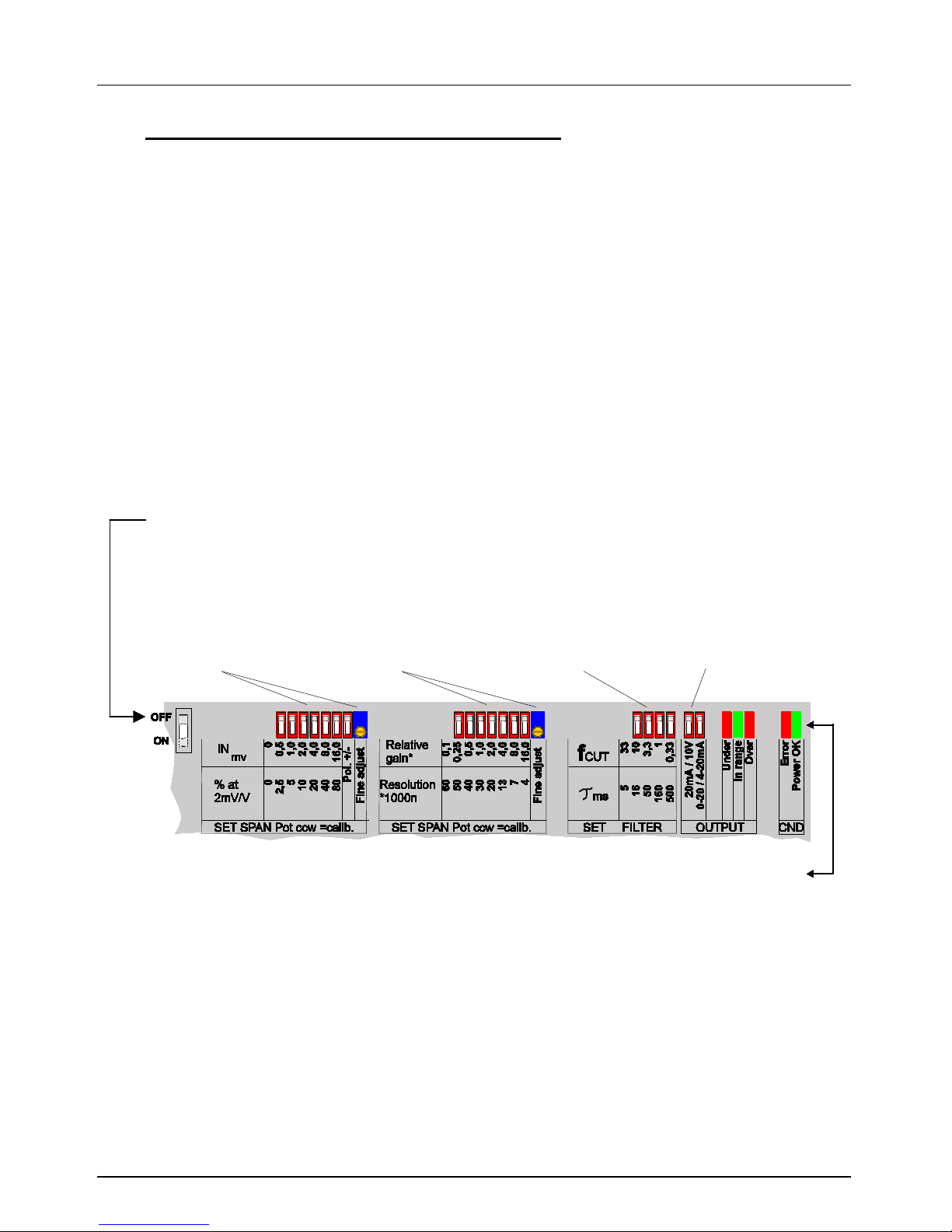
All microswitches and potentiometers are arranged in an easily accessible
location on top of the housing.
Basic setting for all DIP-switches by delivery is the „OFF“-position
(confirms approx. 0mV/V…2mV/V = 0/4…20 mA bzw. 0…10 V)
*ATTENTION: Whe n the 0 -10 Volt output is being used, the “0-20 / 4-20mA”
selector switch mu st al so b e set to 0-20 m A!
DIP switches and potentiometer f or
adjusting the zero
point
DIP switches and potentiometer f or
adjusting the
amplification
DIP switches for l ow
pass filter s et ting
0.33 to 33 Hz
DIP switches for
selecting the analogue
output 0
-20 mA or
4
-20 mA or 0-10V
The LED`s mean:
Power OK
= Power supply is present
Error
= Error signal (in c ombination with Open Collect or out put)
Under range
= Input signal too low (negative)
In range
= Input signal ok
Over range
= Input signal too high
Page 9

Betriebsanleitung/ Operating manual
EZE11
www.tecsis.de BD_BE 945 b 9
2 Micro switch adjustments
2.1 Low pass filter
The four DIP switches make it possible to select filtering in the range of
0.33 Hz to 33 Hz (see table). In the default setting the low-pass filter is set
to 33 Hz, and all DIP switches are in the “OFF ” position. This m eans that
practically no filtering is t aking place, and the response tim e (99.98 of the
signal) of the ZE 11 is therefor e m inimised to about 40 m s. The r esponse
time with filtering of 0.33 Hz is approx. 4000 ms.
DIP Schalter ON
none
1 2 3 4 Time const ant
ms 5 16
50
160
500
setting time ( 99,98%)
ms
40
130
400
1300
4000
cut of frequency
Hz
33
10
3,3
1,0
0,33
2.2 Zero setting
The firs t six micr oswitches make it possible to shift the zero point in steps
of 0.5 mV within a range of 0 to 31.5 mV (see table). The seventh DIP
switch is used to select the polarity of the zero point shift, either positive or
negative. For example, if a preload is being tared/compensated the “/negative” setting must be select ed. The analogue output can be shifted by
up to a maximum of +/- 80% of the nominal load. Fine adjustments are
made using the 20-way helical potentiometer.
DIP switches ON
none
1 2 3 4 5 6 all
Pol
Pot
relative to 20mV
% 0 2,5 5 10
20
40
80
157
+/ -
35
Input at Zero V
out
mV 0 0,5 1 2 4 8
16
31,5
+ /-
0,6
2.3 Span ( gain) setting
The 7 DIP switches and the trim ming potentiometer allow the am plification
of input signals of 1 mV to 32 mV to be adj usted (continuously variable) to
an output signal of 0...10V and 0/4...20mA (see table)
DIP switches ON
none
1 2 3 4 5 6 7
all
pot
rel. gain factor
x 1 0,25
0,5 1 2 4 8
16
33
0,3
Input for 10 V
out
mV
32
30
28
24
16 8 4 2 1
Page 10
Betriebsanleitung/ Operating manual
EZE11
10 BD_BE 945 b www.tecsis.de
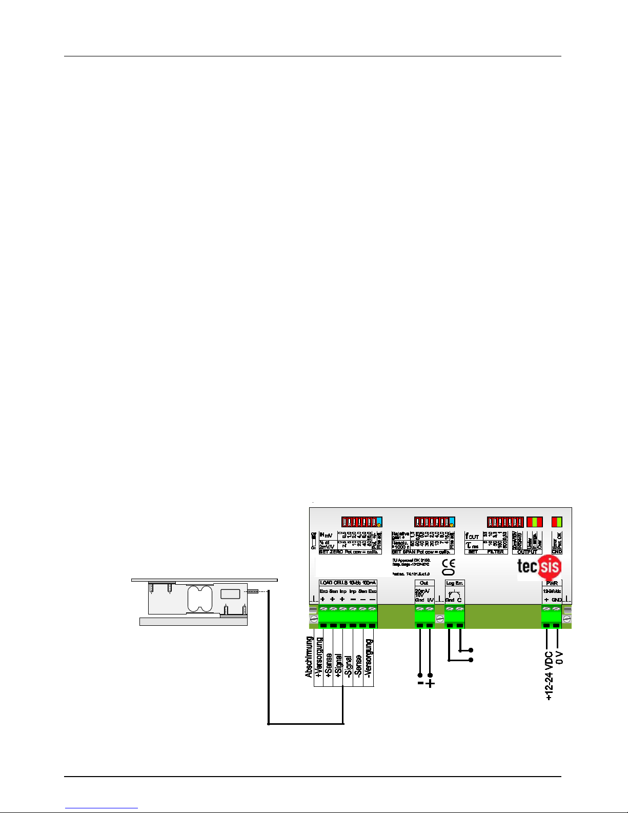
2.4 Calibrating the scale
A digital measuring unit (Multimeter), preferably with a 5-figure display, is
connected to the output of the module (current or voltage output). The
Multimeter should have a res olution of 0.01 m A in the cur rent range so that
calibration to an accuracy of at least 0.05% can take place.
2.5 Zeroing the scale
The scale is now roughly zeroed (tared) with a high or low preload using the
microswitches, and fine adjustments are made using the potentiometer.
The scale is theref ore fully unloaded and then the output signal is set to an
exact output current of 4.00 mA, for example, using the microswitch and
the potentiometer.
2.6 Calibrating the max. scale load, weighing range
Load the scale with a nominal weight (full load) and then adjust the
amplification using the microswitch (rough) and the potentiometer (fine)
until the Multimeter displays exactly 20.00 mA. Repeat procedure (item s 5
and 6) several times. If only part of the nominal scale value is going to be
used, the amplification can be roughly modified by adjusting the
microswitch. For example, if only 50% of the nominal value is needed and
the load cell that is connected has a nom inal character istic value of 2mV/V,
the amplification microswitch is set to 1mV/V (i.e. 10m V) accordingly (see
table).
2.7 Scale ready for operation
The scale is now ready for operation.
Typ. platform 600 x 600 m m
Analogue output:
optionally
0/4...20mA or
0...10V*
Logic output:
Open Collector,
normally closed,
opens if an error
occurs at the EZE11
*ATTENTION:
When the 0
-10 Volt output is
being used, the “0
-20/4-20mA”
selector switch must also be set
to 0
-20mA !
EZE11
Page 11

Betriebsanleitung/ Operating manual
EZE11
www.tecsis.de BD_BE 945 b 11
3 Technical specifications
Linearity 0 to F.S
max. deviation < 0,01 %
Input signal
0,1 mV/V to 3,5 mV/V,
rough and fine adjustable
Bridge supply voltage
10 VDC, for 1-4 load cells
350 Ω up to 2000Ω,
active sense switching for wires length
up to 100 m
Safety circuit
Logic output, Open Collector,
normally closed, fail safe, releases if
load cell input , sense voltage, output
voltage or power supply is out of
range
max. load rating 30VDC, 300mA
Zero point adjustment
(offset)
up to 80 % freely adjustable
Current loop output
0 - 20 mA or
4 - 20 mA /500 Ω max, short circuit
protected
Voltage output
+/- 10 V output, R
Load
> 500 Ω
Active filters
0,33...33 Hz cut off freq,
variable in steps
Comp. temperature range
storage
- 10° C to + 40° C,
-20°C to + 60° C
Temp. effect on zero
< ±25 ppm/° C
Temp. efect on gain
< ±50 ppm/° C
Case
135 x 66 x 28 mm,
weight approx.. 200g, IP40,
with TS35-clips for mounting on DIN
rail, (other case types on request)
Power supply
12 ... 24 VDC + 10/- 15% or
14...18VAC, 3W max.,
not galvanically isolated
Subject to technical alternations
Page 12

Betriebsanleitung/ Operating manual
EZE11
12 BD_BE 945 b www.tecsis.de
tecsis GmbH
Carl
-Legien-Straße 40
D
-63073 Offenbach am Main
Telefon:
+ 49 69 5806-0
Telefax:
+49 69 5806-170
E
-Mail: [email protected]
Internet: www.tecsis.de
 Loading...