

Page 1
Kraft Druck Temperatur Schalten Service
Force Pressure Temperature Switch Service
Betriebsanleitung
Operating manual
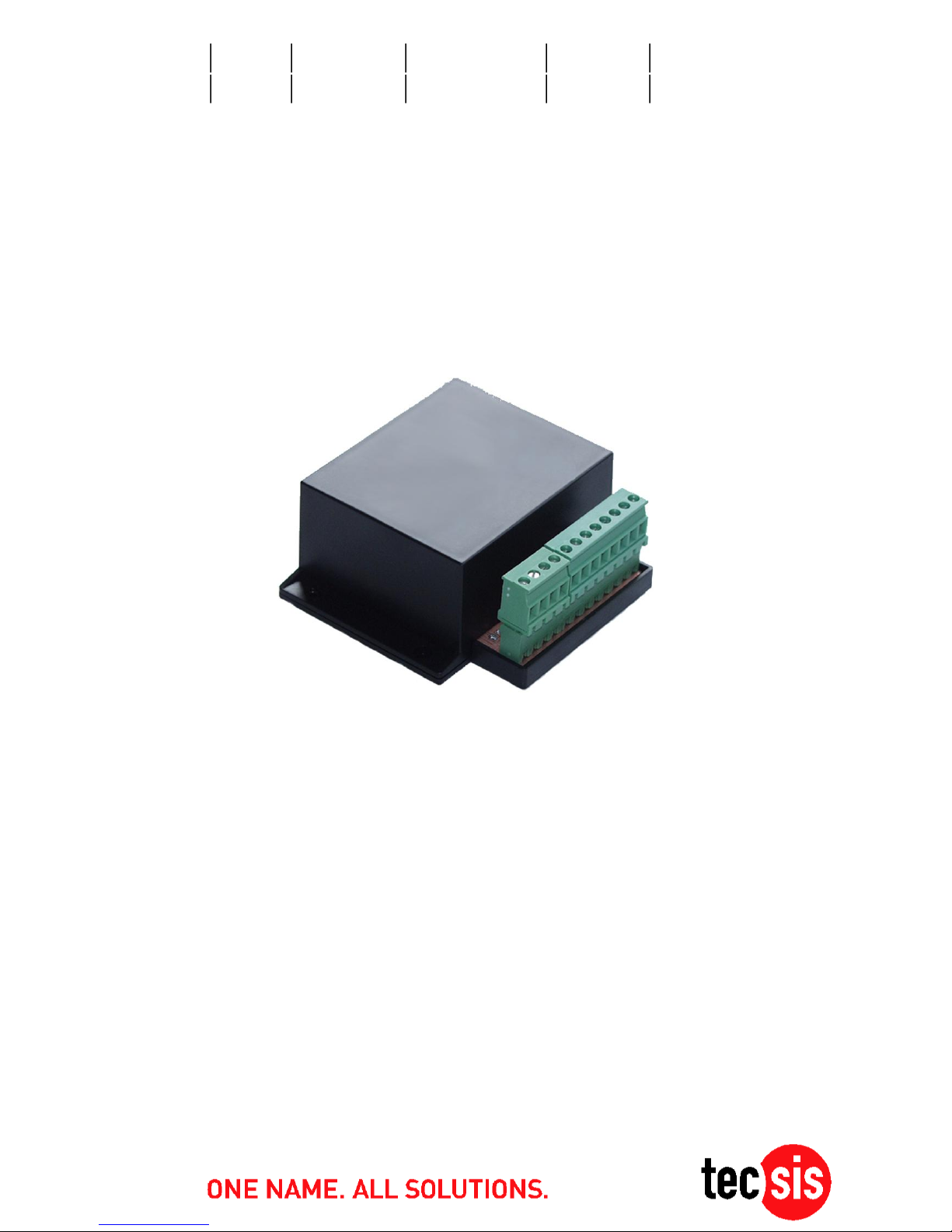
EGS08
Grenzwertschalter
Limit switch
BD_BE 989 e
Page 2

Betriebsanleitung/Operating manual
EGS08
2 BD_BE 989 e www.tecsis.de
Inhalt
1 Funktionsbeschreibung 3
2 Anschlussbelegung 4
3 Technische Daten 12
D
English version page 13
Page 3
Betriebsanleitung/Operating manual
EGS08
www.tecsis.de BD_BE 989 e 3
1 Funktionsbeschreibung
Die Baugruppe arbeitet als Dreifachkomparator für Sensoren mit Stromausgang.
Der Sensoreingang ist für den 1-9mA oder 4-20mA Signalstrombereich
konfigurierbar.
Ein Abgleichpotentiometer je Komparator ermöglicht die Einstellung von je einer
Schaltschwelle, die einer bestimmten Belastung des angeschlossenen DMSKraftaufnehmers entspricht. Jeder Komparatorausgang steuert ein Relais und
eine Kontroll - LED. Die Schaltfunktion jedes Relais kann zwischen zu- oder
abschaltend bei Schwellwertüberschreitung eingestellt werden. Ein Zusatzkomparator schaltet alle Relais bei Kabelbruch des Sensors in den
Überlastzustand.
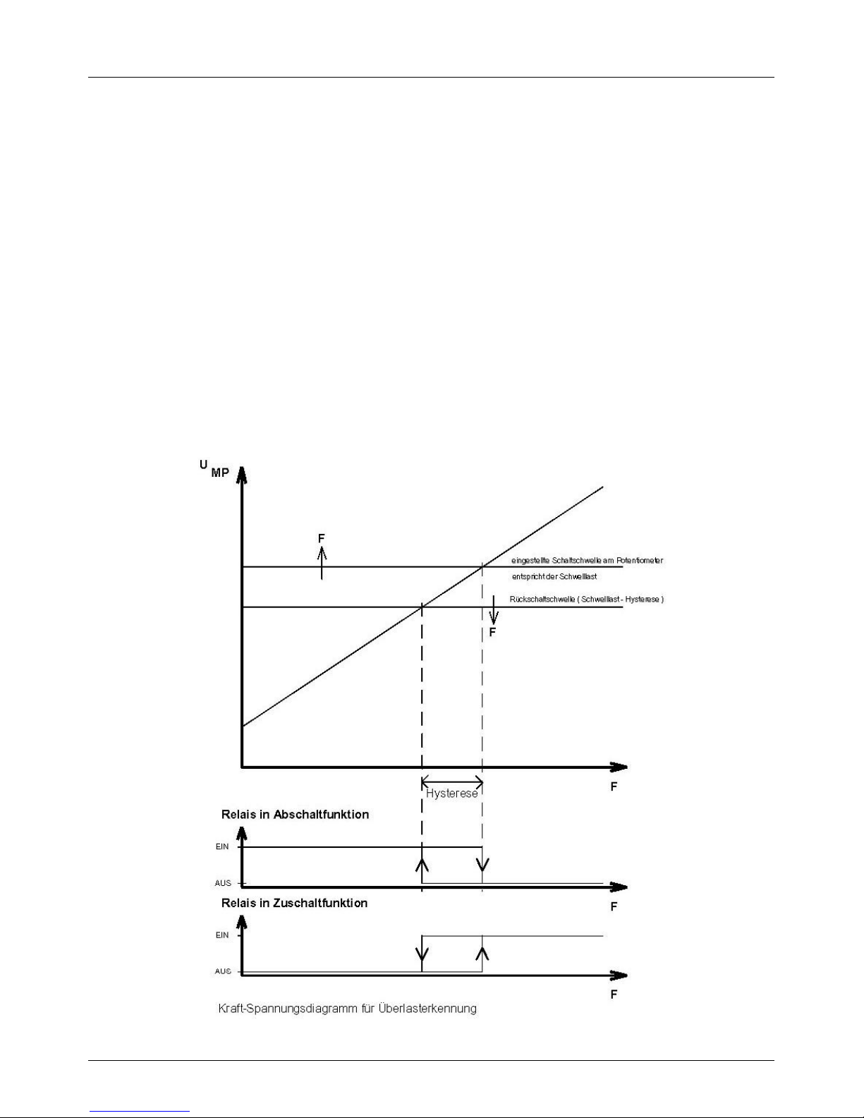
Das nachfolgende Diagramm zeigt grafisch das Funktionsprinzip jedes
Komparators.
Page 4
Betriebsanleitung/Operating manual
EGS08
4 BD_BE 989 e www.tecsis.de
Danach führt eine Zunahme der Kraft zu einer Erhöhung der Messspannung.
Durch Verdrehen eines der Regler POT1, 2 oder 3 wird die Schaltschwelle für
den jeweiligen Komparator verändert. Für den Fall einer zunehmenden Kraft
wird beim Erreichen der Schaltschwelle das nachgeschaltete Relais des
Komparators umgeschaltet. Nimmt die Kraft am DMS-Kraftaufnehmer wieder ab,
sinkt die Messspannung. Mit dem Erreichen der Rückschaltschwelle des
Komparators wird das Relais wieder zurückgeschaltet. Zwischen der Ausschaltund der Einschaltschwelle besteht eine Differenz - Hysterese, die als Spannung
ausgedrückt, einen Wert von ca. 20mV oder 70mV hat. Damit wird ein Flattern
des Relais bei sehr kleinen Kraftschwankungen vermieden.
Im ausgeschalteten Zustand bzw. bei Unterbrechung der Stromversorgung sind
alle Relais abgefallen. Bei defektem oder nicht vorhandenem Sensor befinden sich
alle Relais im Überlastzustand. Parallel zur Relaisspule ist eine Kontroll-LED
geschaltet. Sie leuchtet, solange das Relais angezogen hat.
Die Baugruppe ist in einem Gehäuse untergebracht. Alle externen Anschlüsse sind
ohne Demontage des Gehäuses zugänglich. Zur Einstellung der Potentiometer,
Konfigurationen oder Messungen muss die Gehäusehaube abgenommen werden.
Die Stromversorgung erfolgt mit einer Wechselspannung von maximal 26VAC oder
einer Gleichspannung bis maximal 30VDC.
2 Anschlussbelegung
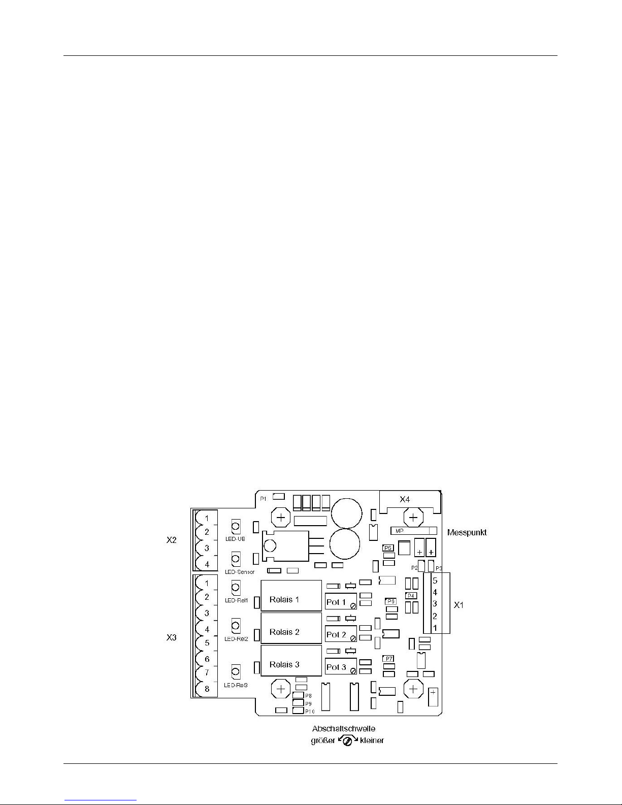
Die Bestückungszeichnung zeigt die Lage der Anschlussklemmleiste n und die
Regler für die Komparatoreinstellungen:
Page 5
Betriebsanleitung/Operating manual
EGS08
www.tecsis.de BD_BE 989 e 5
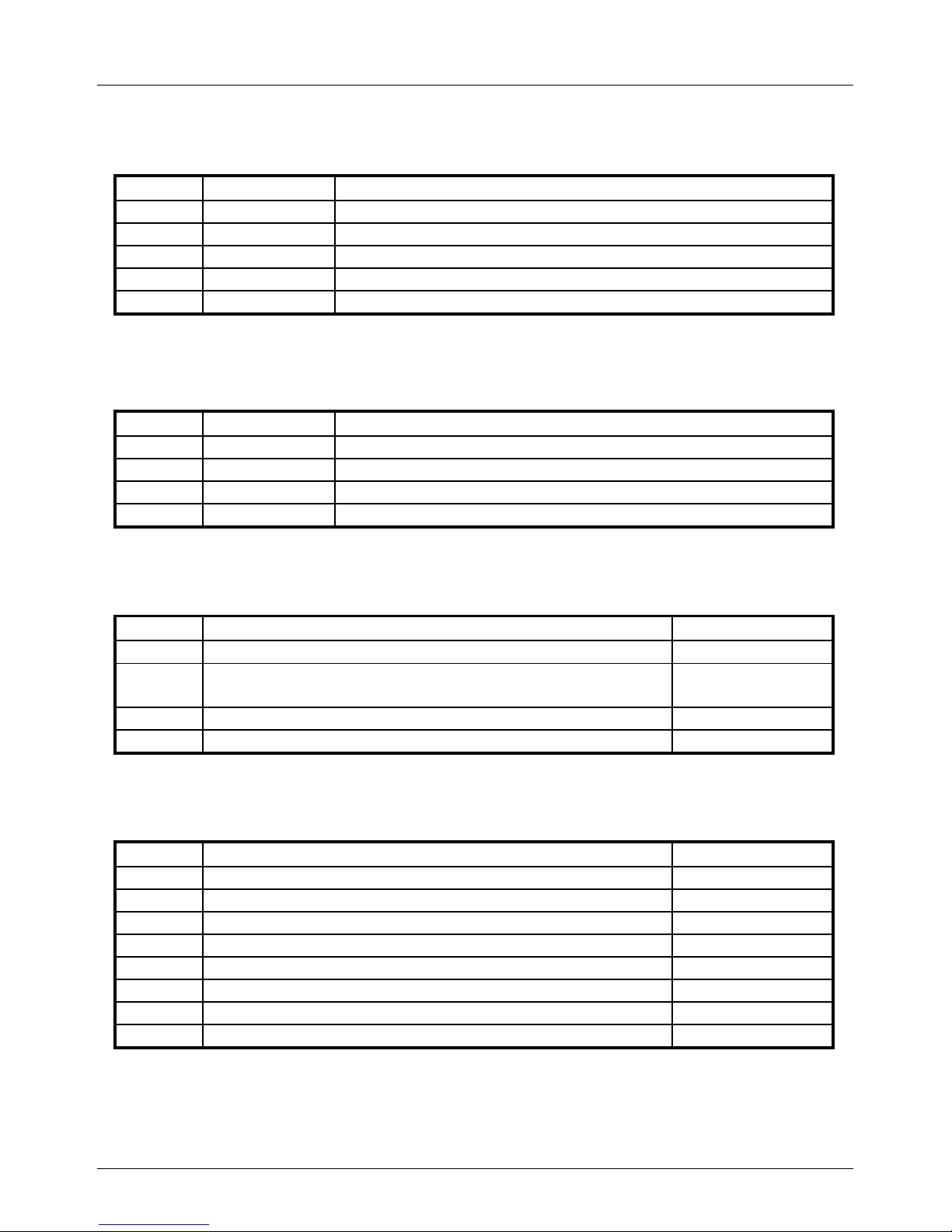
Anschlussklemmleiste X1 für 3-Leitertechnik
Anschl.
Bezeichnung
Bemerkung
1
UB
Betriebsspannung Sensor 21VDC (intern erzeugt)
2
GND
Masse
3
Im
Sensorsignal 1-9mA oder 4-20mA
4
nicht belegt
5 Schirm
Schirmung des Anschlusskabels
Anschlussklemmleiste X1 für 2-Leitertechnik
Anschl.
Bezeichnung
Bemerkung
1
UB
Betriebsspannung Sensor 21VDC (intern erzeugt)
3
Im
Sensorsignal 1-9mA oder 4-20mA
4
nicht belegt
5 Schirm
Schirmung des Anschlusskabels
Anschlussklemmleiste X2
Anschl.
Bezeichnung
Regler
1
24 VAC Stromversorgung oder +24 VDC Versorgung
2
24 VAC Stromversorgung oder 24 VDC Versorgung
( GND)
3
nicht belegt
4
Masse
Anschlussklemmleiste X3
Anschl.
Bezeichnung
Regler
1
Relais 1, Arbeitskontakt
2
Relais 1, Mittelkontakt
POT 1
3
Relais 2, Arbeitskontakt
4
Relais 2, Ruhekontakt
5
Relais 2, Mittelkontakt
POT 2
6
Relais 3, Arbeitskontakt
7
Relais 3, Ruhekontakt
8
Relais 3, Mittelkontakt
POT 3
Page 6
Betriebsanleitung/Operating manual
EGS08
6 BD_BE 989 e www.tecsis.de
Messpunkte und Anschlussklemmleiste X4:
Auf der Leiterplatte befindet sich für Kontrollzwecke eine 6 polige Buchsenleiste „MP“ zur
Überprüfung der Funktion des Kraftaufnehmers und der Einstellwerte. Ein Stecker mit
gleicher Pinbelegung ist für den Anschluss eines Servicegerätes vorgesehen.
Anschl.
Signal
1
UB ( 5V )
2
GND
3
Messspannung
4
Einstellwert POT1
5
Einstellwert POT2
6
Einstellwert POT3
Die Messspannung wird über eine Bürde von 360 bei 1-9mA Sensor oder 180 bei 420mA Sensor gewonnen. Ein konfigurierbarer Tiefpass dämpft das Sensorsignal und stellt
dieses dem Messpunkt und den Komparatoren zur Verfügung.
Page 7
Betriebsanleitung/Operating manual
EGS08
www.tecsis.de BD_BE 989 e 7
Konfigurationsmöglichkeiten
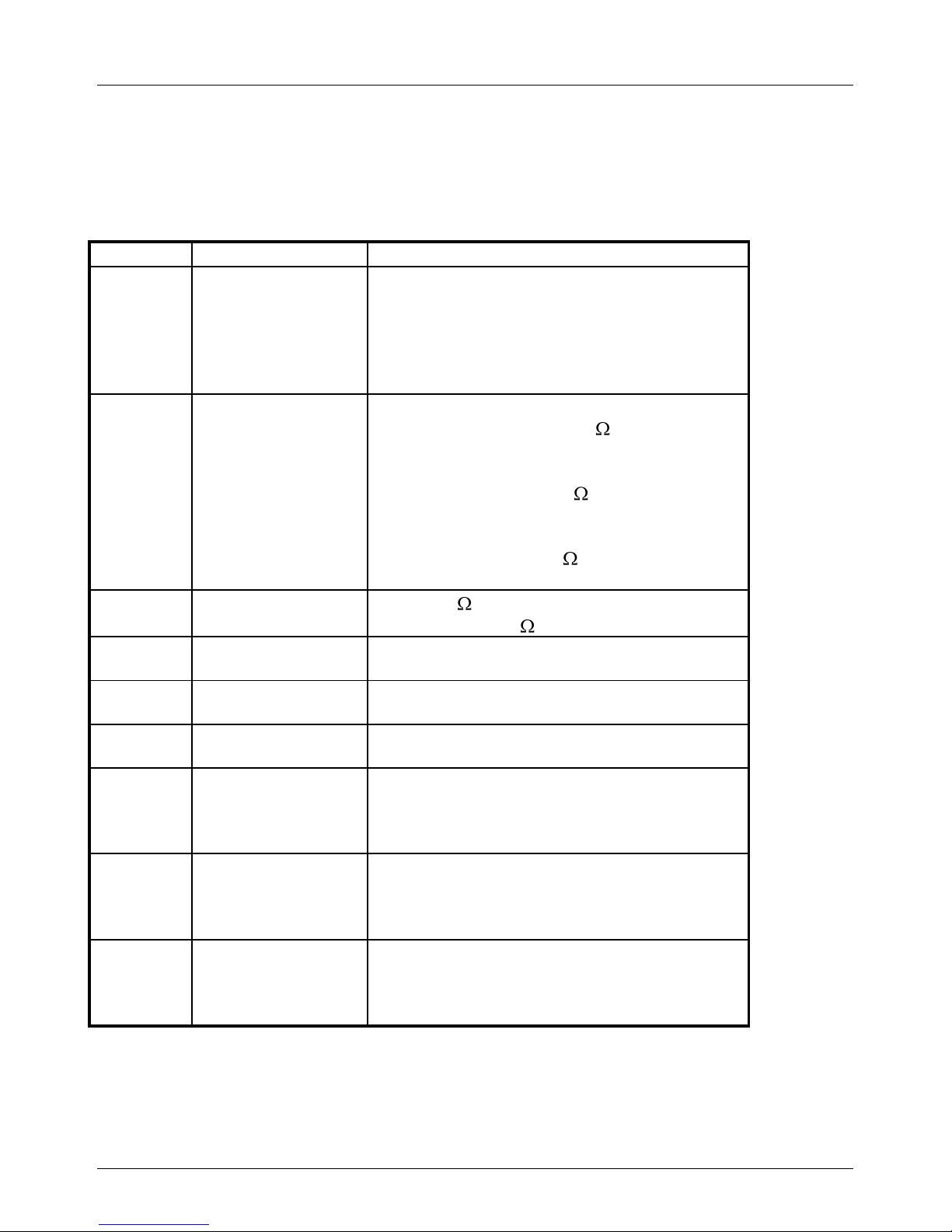
Die Lötbrücken P1 bis P10 dienen der Konfiguration der Schaltung und damit der
Anpassung an den konkreten Einsatzfall.
Brücke
Funktion
Funktion
P1
offen
geschlossen
Wechselspannungsspeisung
Gleichspannungsspeisung
( nur nötig, wenn GND an X2–2 und GND
X1-2 gleiches Potential besitzen müssen)
P2, P3
Signaldämpfung
Messeingang
P2=offen P3=offen/
schwache Dämpfung (10k , 0,1µF)
P2=offen P3=geschlossen/
mittlere Dämpfung (10k , 10,1µF)
P2=geschlossen P3=geschlossen/
starke Dämpfung (10k , 20,1µF)
P4 Bürdewiderstand
offen 360
geschlossen 180
P5 Hysterese
Komparator 1
offen 20mV
geschlossen 70mV
P6 Hysterese
Komparator 2
offen 20mV
geschlossen 70mV
P7 Hysterese
Komparator 3
offen 20mV
geschlossen 70mV
P8 Schaltfunktion
Relais 1
offen - Relais fällt bei Überschreitung der
Schwelle ab
geschlossen - Relais zieht bei
Überschreitung der Schwelle an
P9 Schaltfunktion
Relais 2
offen - Relais fällt bei Überschreitung der
Schwelle ab
geschlossen - Relais zieht bei
Überschreitung der Schwelle an
P10
Schaltfunktion
Relais 3
offen - Relais fällt bei Überschreitung der
Schwelle ab
geschlossen - Relais zieht bei
Überschreitung der Schwelle an
Page 8
Betriebsanleitung/Operating manual
EGS08
8 BD_BE 989 e www.tecsis.de
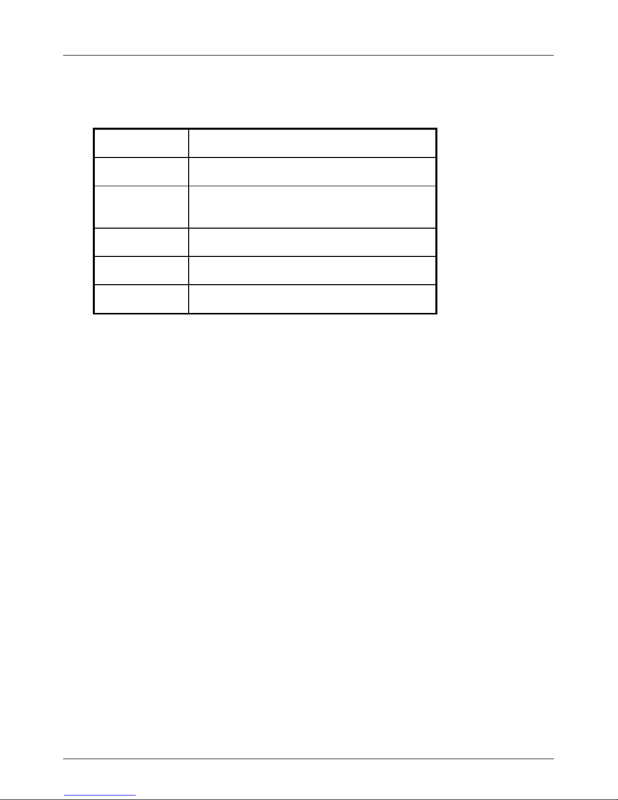
Kontroll LED
LED
Anzeigefunktion
LED-UB
Stromversorgung liegt an
LED-Sensor
Der Sensor ist angeschlossen und die
Messspannung beträgt mindestens 0,25V.
LED-Rel1
Relais 1 angezogen
LED-Rel2
Relais 2 angezogen
LED-Rel3
Relais 3 angezogen
Page 9
Betriebsanleitung/Operating manual
EGS08
www.tecsis.de BD_BE 989 e 9
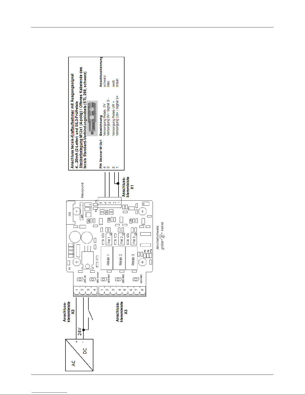
Anschluss tecsis-Kraftaufnehmer mit Ausgangssignal
4…20mA (2-Leiter) und SIL3-Prüfrelais
Page 10
Betriebsanleitung/Operating manual
EGS08
10 BD_BE 989 e www.tecsis.de
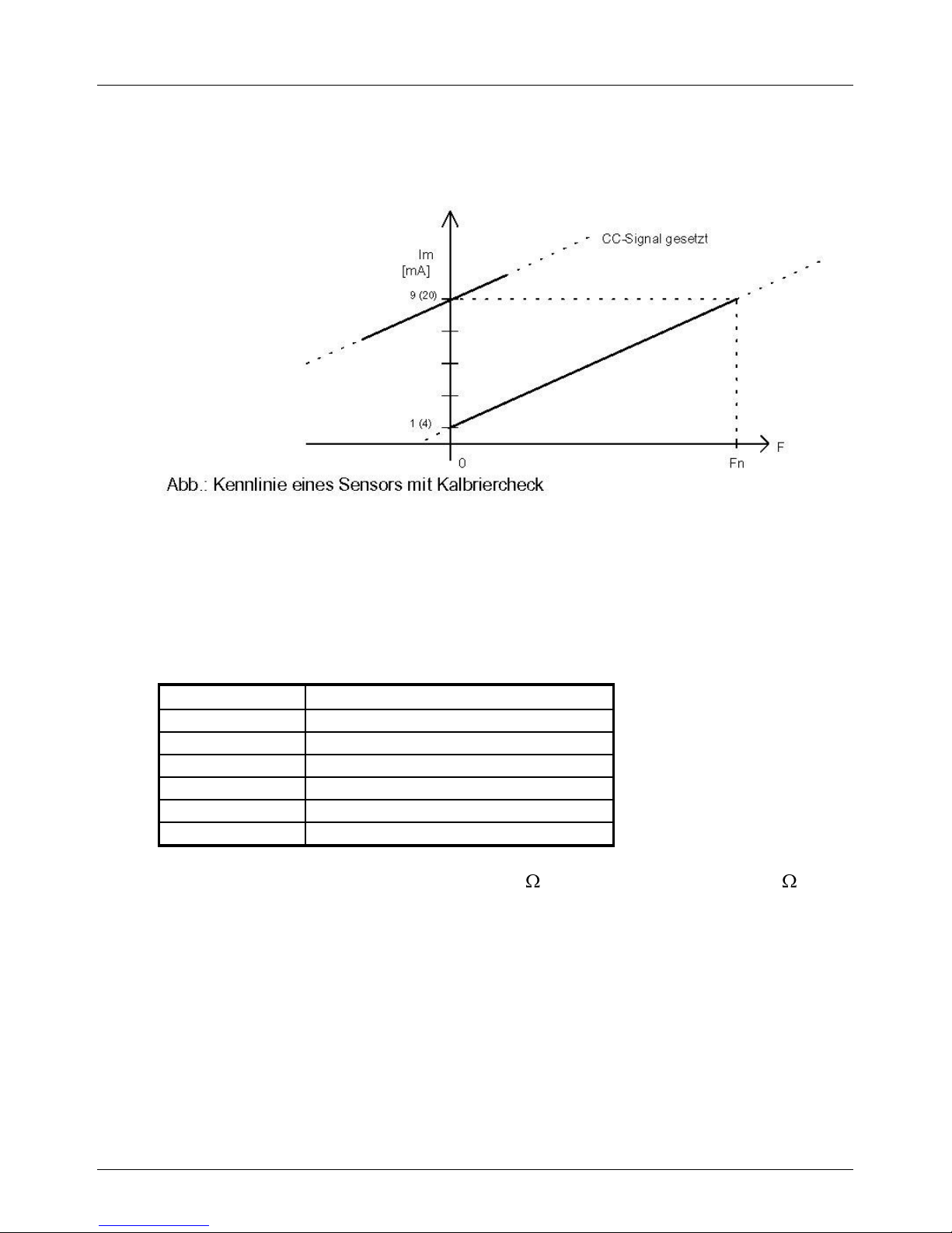
Bei Verwendung von tecsis-Kraftaufnehmern mit Prüfrelais ( 4…20mA - 2-Leiter
für SIL3-Anwendungen) wird, durch die Verbindung des Kontaktes Klemme 3 an
der Anschlussklemmleiste X2 (Aktivierung Prüfrelais für Signalsprung) mit der
Masse (GND), der am Kraftaufnehmer werkseitig nach Kundenwunsch
eingestellte Signalsprung ausgelöst.
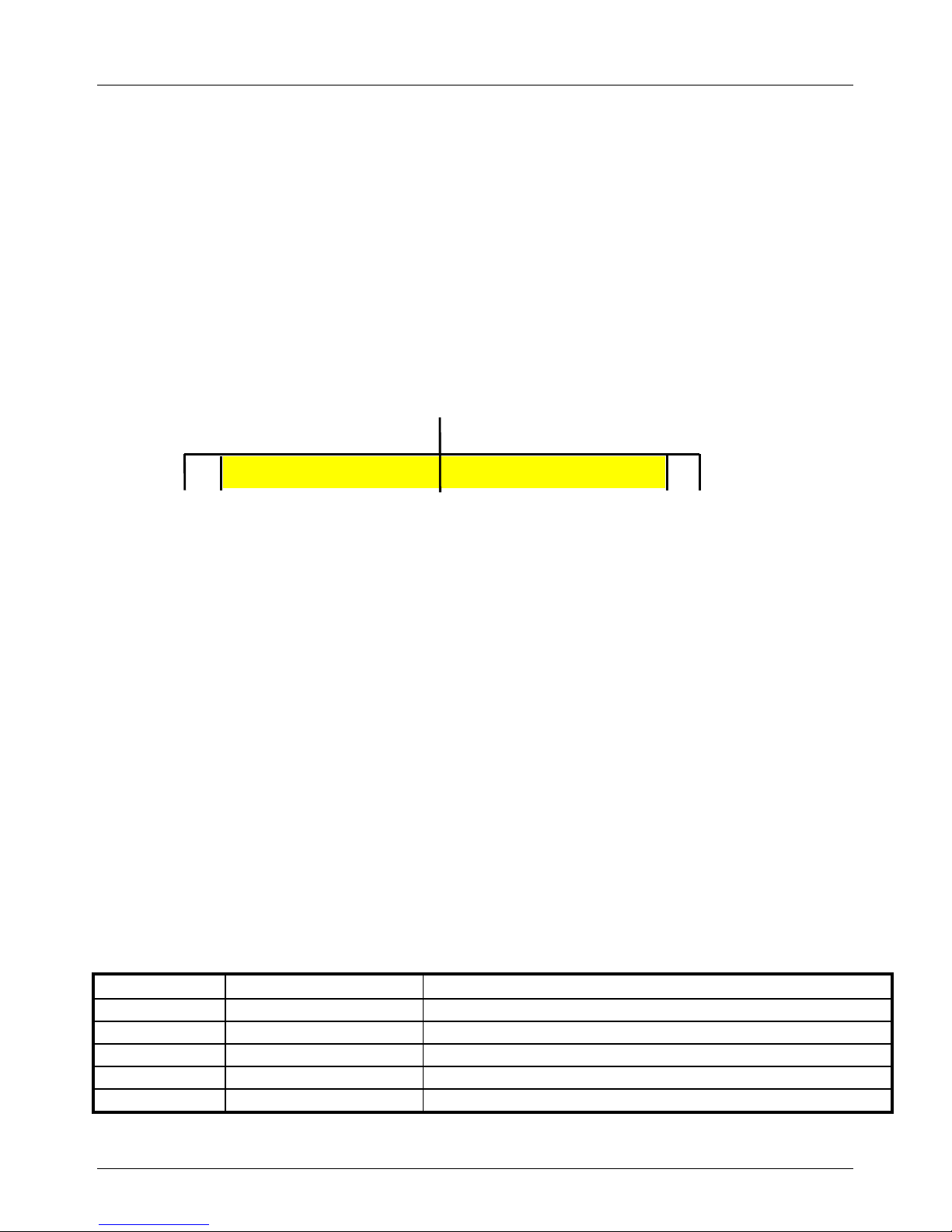
Die Standardeinstellung der Kraftaufnehmer mit Stromausgang 4...20 mA zur
Überlasterkennung ist z.B.:
Mit einem fest eingestellten Signalhub von 8 mA wird dann in jedem
Betriebszustand bei Aktivierung des Prüfrelais der Überlastpunkt überschritten.
Die obere Messbereichsgrenze von 20 mA wird jedoch nicht erreicht und dadurch
die Überprüfung des Signalhubs ermöglicht (siehe dazu für weitere Informationen
auch die Datenblätter der entsprechenden tecsis-Kraftaufnehmer).
Anschlussklemmleiste X1 für 3-Leitertechnik
Anschl.
Bezeichnung
Bemerkung
1
UB
Versorgungsspannung Sensor 21VDC (intern erzeugt)
2
GND
Masse
3
Im
Sensorsignal 1-9mA oder 4-20mA
4
--
-- 5 Schirm
Schirmung des Anschlusskabels
3,8
41220
21
Kabelbruch
Kurzschluss
[mA]
Überlastpunkt
(125% Nennlast)
Page 11
Betriebsanleitung/Operating manual
EGS08
www.tecsis.de BD_BE 989 e 11
Anschlussklemmleiste X1 für 2-Leitertechnik
Anschl.
Bezeichnung
Bemerkung
Anschluss tecsis-Kraftaufnehmer mit
Ausgangssignal 4…20mA (2-Leiter)
und SIL3-Prüfrelais
Steckerbelegung M12x1 (4-polig) /
Offenes Kabelende des tecsis StandardVerbin-dungskabels (STL 288, schwarz)
PIN M12x1
Bezeichnung
Anschlusskennung
1
UB
Versorgungsspannung Sensor
und Relais 21VDC
(intern erzeugt)
1 und
2
Vers. UB+ /
Signal S+
Vers. Relais
UR +
braun
weiß
3
Im
Sensorsignal 19mA oder 4-20mA
3
Vers. 0V /
Signal S -
blau
4
Prüfrelais
Versorgung Relais
0 V
4
Vers. Relais
0V
schwarz
5
Schirm
Schirmung des
Anschlusskabels
Gewinde
M12x1
Schirm
Schirm
Anschlussklemmleiste X2
Anschl.
Bezeichnung
Regler
1
24 VAC Stromversorgung oder +24 VDC
Versorgung
2
24 VAC Stromversorgung oder 24 VDC
Versorgung
( GND)
3
Aktivierung Prüfrelais für Signalsprung
(durch Verbindung mit Masse (GND))
4
Masse
Anschlussklemmleiste X3
Anschl.
Bezeichnung
Regler
1
Relais 1, Arbeitskontakt
2
Relais 1, Mittelkontakt
POT 1
3
Relais 2, Arbeitskontakt
4
Relais 2, Ruhekontakt
5
Relais 2, Mittelkontakt
POT 2
6
Relais 3, Arbeitskontakt
7
Relais 3, Ruhekontakt
8
Relais 3, Mittelkontakt
POT 3
Page 12

Betriebsanleitung/Operating manual
EGS08
12 BD_BE 989 e www.tecsis.de
3 Technische Daten
Stromversorgung: 24VDC (-10%/+40%)
Stromaufnahme: max. 100mA (ohne Sensor)
Eingang DMS-Sensor: Stromeingang 1-9mA oder 4-20mA
Sensorversorgung: 21V DC
Ausgänge: 3 Relaisausgänge (Spezifikation siehe unten)
Bürdewiderstand: 360 oder 180
Kabelbrucherkennung: Freigabe Relaisfunktionen
ab 0,7mA Signalstrom bei 1-9mA Bürde
ab 1,4mA Signalstrom bei 4-20mA Bürde
Gehäuse: 80 * 67 * 41 mm³
Befestigung Gehäuse: zwei Bohrungen 3,2mm
diagonal 45 * 89 mm²
Einsatztemperaturbereich: 0°C … 70°C
Schutzart IP20
Spezifikation der eingesetzten Relais RD2N-1U:
30W 1,25A DC ( ohmsch)
30W 100V DC ( ohmsch)
60VA 1,25A AC ( ohmsch)
60VA 125V AC ( ohmsch)
20VA 1,25A AC ( induktiv)
20VA 125V AC ( induktiv)
Page 13

Betriebsanleitung/Operating manual
EGS08
www.tecsis.de BD_BE 989 e 13
Content
1 Functional description 14
2 Pin assignment 15
3 Technical data 22
GB
Page 14
Betriebsanleitung/Operating manual
EGS08
14 BD_BE 989 e www.tecsis.de
1 Functional description
The units operate as triple comparators for sensors with current output.
The sensor input can be configured for the 1-9mA or 4-20mA signal range.
An adjustable potentiometer per comparator enables the setting of a switching
threshold for each one which corresponds to a certain loading of the connected
strain gauge force transducers. Each comparator output controls a relay and an
indicator LED. The switching function of each relay can be set to closed or switchoff should the threshold value be exceeded. An additional comparator switches all
relays to the overload condition if there is a broken wire from the sensor.
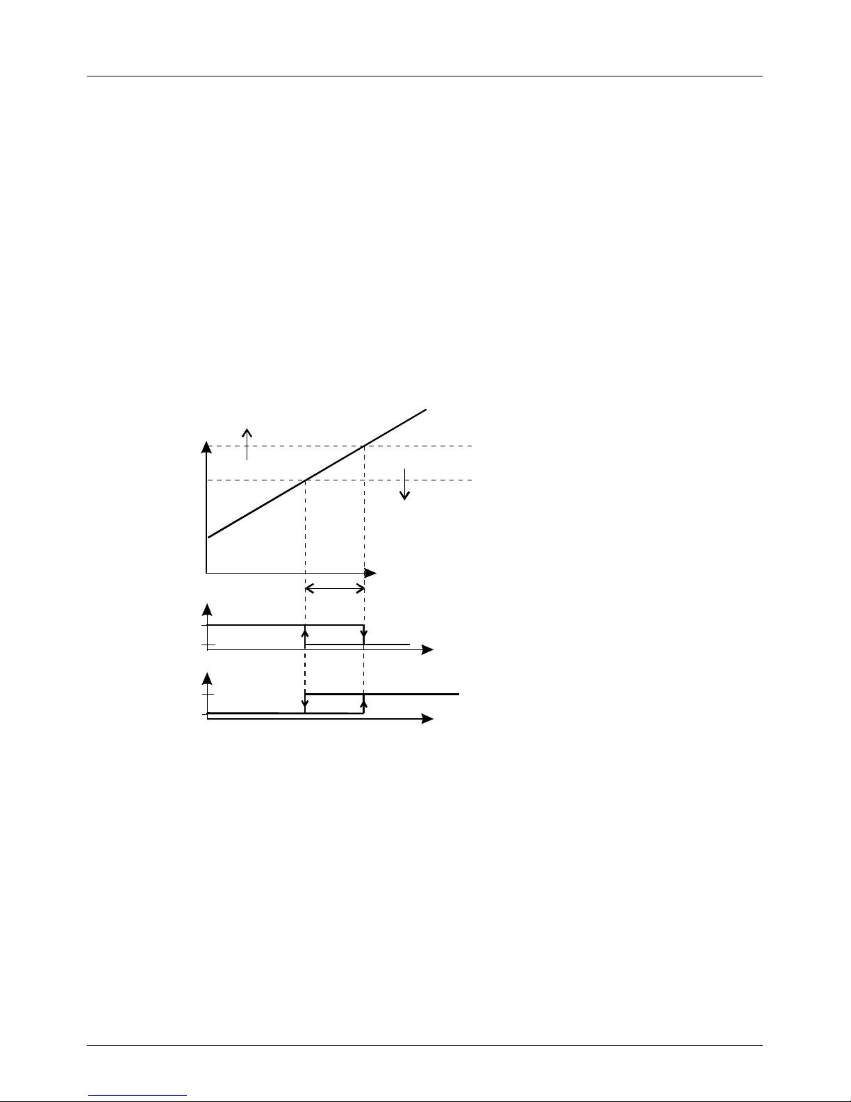
The diagram below shows the principle of operation graphically for each
comparator.
According to this an increase in the force leads to an increase in the voltage
measured.
By turning one of the controllers POT1, 2 or 3 the switching threshold for that
comparator is changed. If the force is increasing when the switching threshold is
reached the connected relay of the comparator is switched over. If the force on the
strain gauge force transducer is reduced again, the voltage measured falls. When
the switch back threshold of the comparator is reached the relay is switched back
again. Between the switching off and switching on thresholds there is a hysteresis
difference, which expressed as a voltage has a value of about 20mV or 70mV.
Thus, fluttering of the relay when there are very small force variations is avoided.
hysteresis
On
On
Off
Off
F
F
F
F
MP
adjusted switching threshold at the Potentiometer
corresponds to the swelling force
shift-in switching threshold (swelling force - hysteresis)
Relay in switch off mode
Relay in switch on mode
F
U
Page 15
Betriebsanleitung/Operating manual
EGS08
www.tecsis.de BD_BE 989 e 15
In the switched off condition or when the power supply is cut off all the relays drop
out. If there is a defect or the sensor is not present all relays are in the overload
condition. A check LED is connected in parallel with the relay coil. It lights up as
long as the relay has pulled-in.
The unit is fitted in a housing. All external connections are accessible without
removing the housing. The housing cover must be removed to adjust the
potentiometer, configurations or measurements.
The power supply is an ac voltage of 26V ac maximum or a dc voltage of up to 30
V dc maximum.
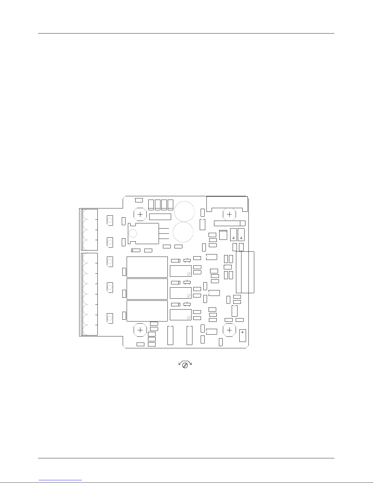
2 Pin assignment
The assignment drawing shows the position of the terminals and the controller for
the comparator settings:
Switch Off threshold
less forcemore force
Relay 2
Relay 1
Relay 3
Pot 1
Pot 2
Pot 3
1
2
3
4
5
X2
X1
P1
P3
P2
P4
P5
P6
P7
P8
P9
P10
Measuring point
LED-UB
LED-Sensor
LED-Rel1
LED-Rel2
LED-Rel3
X3
1
2
3
4
1
2
3
4
5
6
7
8
X4
MP
Page 16
Betriebsanleitung/Operating manual
EGS08
16 BD_BE 989 e www.tecsis.de
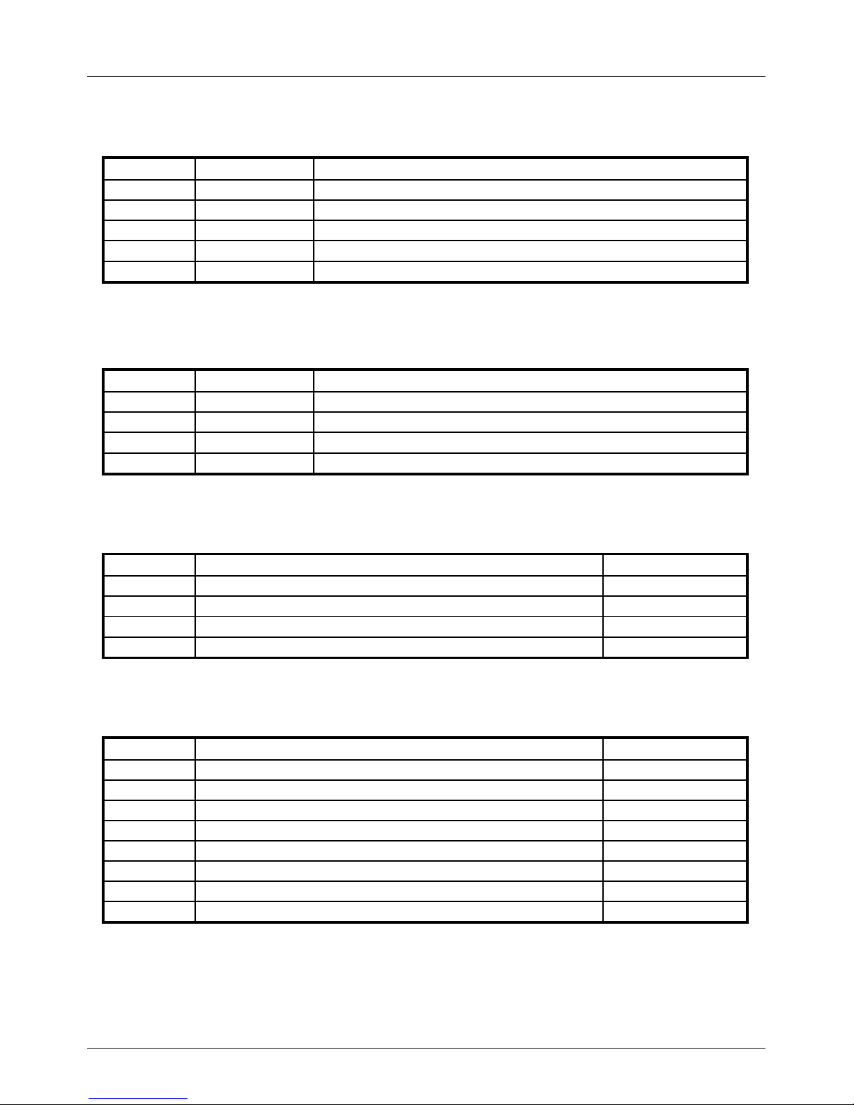
Terminal X1 for 3 wire technology
Terminal
Designation
Remarks
1
UB
Operating voltage sensor 21V dc (produced internally)
2
GND
Mass
3
Im
Sensor signal 1-9mA or 4-20mA
4
not used
5
Screen
Screening of the connection wiring
Terminal X1 for 2 wire technology
Terminal
Designation
Remarks
1
UB
Operating voltage sensor 21V dc (produced internally)
3
Im
Sensor signal 1-9mA or 4-20mA
4
not used
5
Screen
Screening of the connection wiring
Terminal X2
Terminal
Designation
Controller
1
24 V ac power supply or +24 V dc supply
2
24 V ac power supply or 24 V dc supply (GND)
3
not used
4
Mass
Terminal X3
Terminal
Designation
Controller
1
Relay 1, main contact
2
Relay 1, centre contact
POT 1
3
Relay 2, main contact
4
Relay 2, normally closed contact
5
Relay 2, centre contact
POT 2
6
Relay 3, main contact
7
Relay 3, normally closed contact
8
Relay 3, centre contact
POT 3
Page 17
Betriebsanleitung/Operating manual
EGS08
www.tecsis.de BD_BE 989 e 17
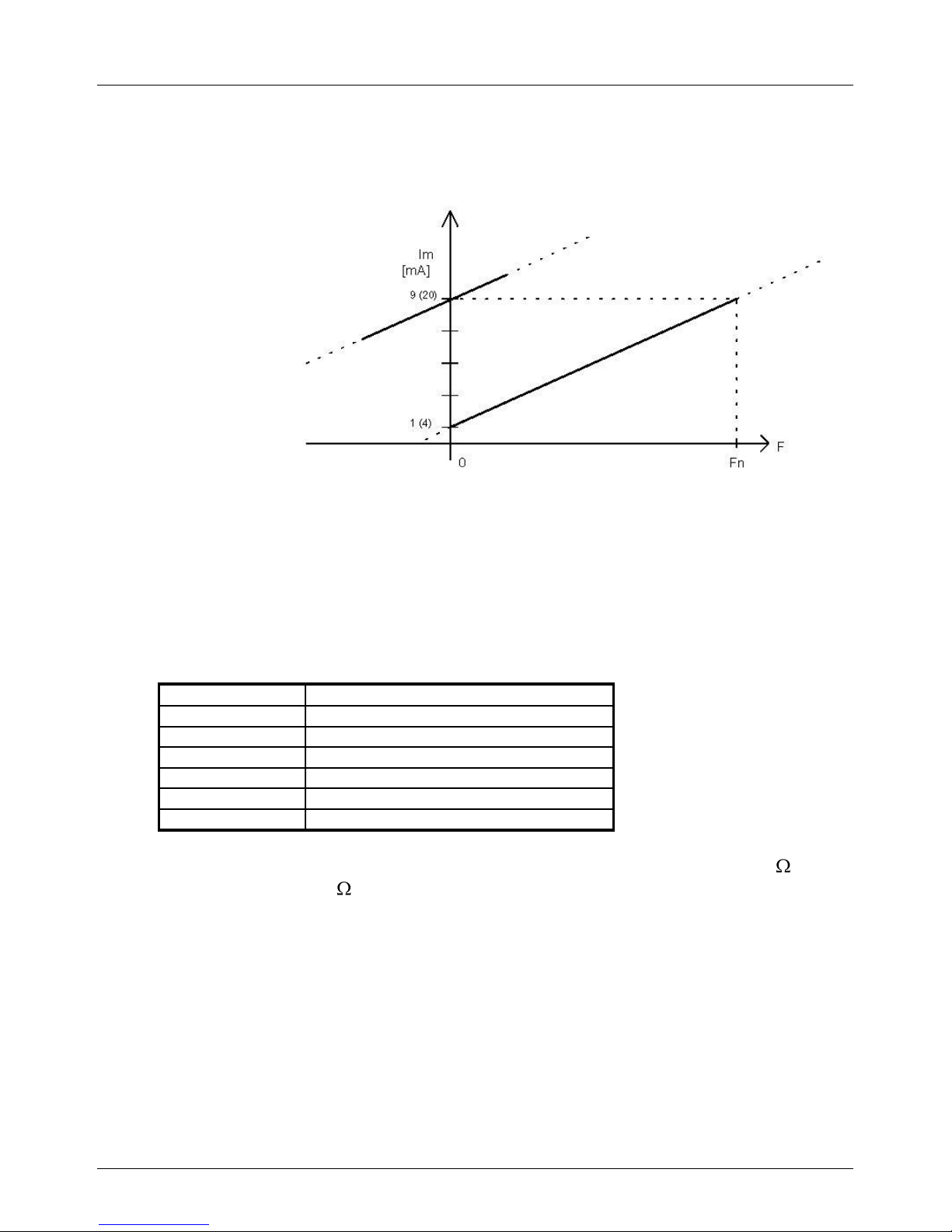
Measuring points and terminal X3:
On the printed circuit board there is a 6 pole socket terminal strip ”MP” to check the
function of the force transducer and the setting values. A plug with the same pin
allocation is provided for the connection of a service instrument.
Terminal
Signal
1
UB ( 5V )
2
GND
3
Measuring voltage
4
Setting value POT1
5
Setting value POT2
6
Setting value POT3
The measurement voltage is picked up from a working resistance of 360 with a
1-9mA sensor or 180 with a 4-20mA sensor. A deep pass that can be configured
damps the signal from the sensor and makes it available to the measuring point
and the comparators.
Fig.: characteristic curve of the sensor with calibration check
Page 18
Betriebsanleitung/Operating manual
EGS08
18 BD_BE 989 e www.tecsis.de
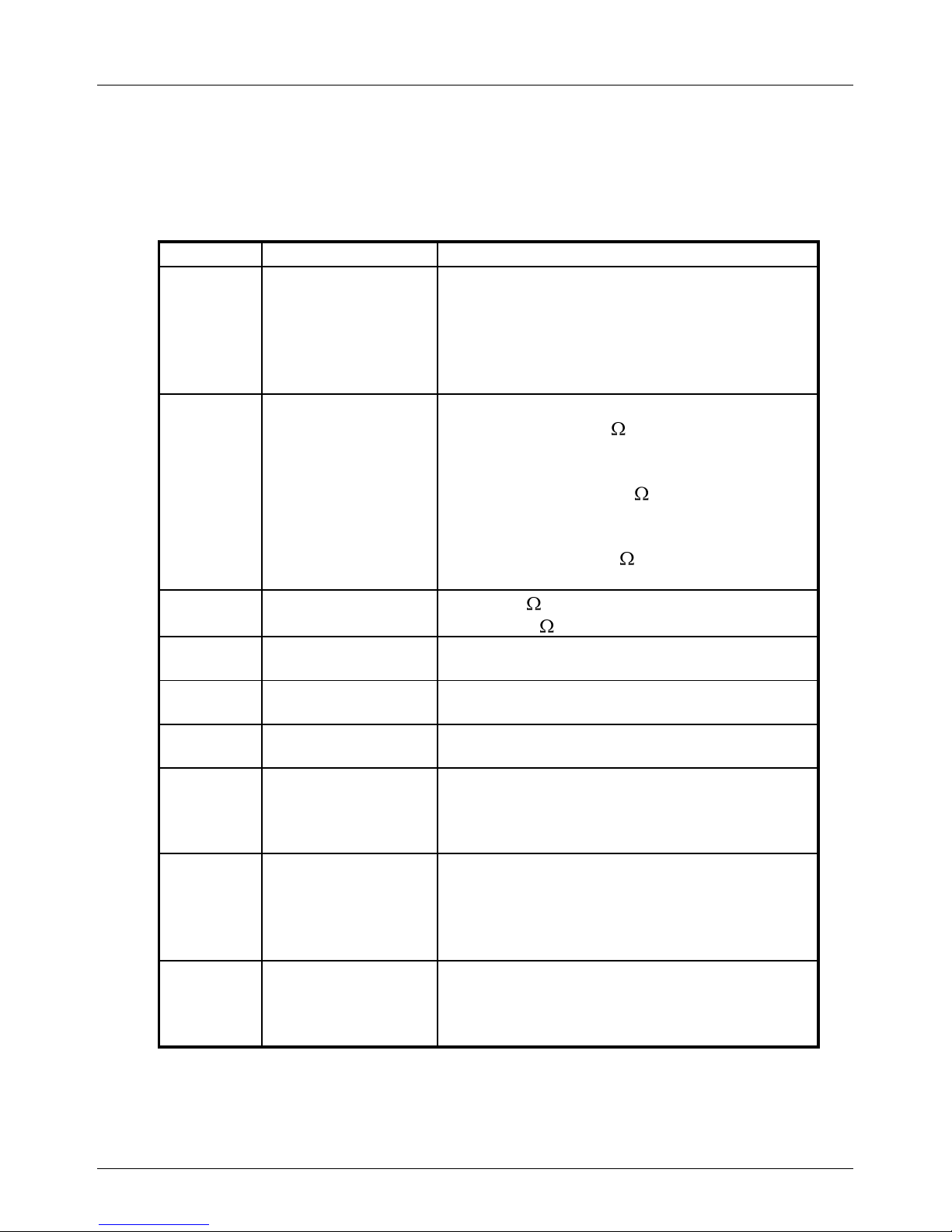
Configuration possiblilities
The solder bridges P1 to P10 serve to configure the circuit and thus adapt it to the
concrete application case.
Bridge
Function
Function
P1
open
closed
Alternating current power supply
Direct current power supply
(only necessary when GND on X2-2 and
GND X1-2 must have the same potential)
P2, P3
Signal damping
measurement
input
P2=open P3=open/
weak damping (10k , 0.1µF)
P2=open P3=closed/
medium damping (10k , 10.1µF)
P2=closed P3=closed/
strong damping (10k , 20.1µF)
P4 Load resistance
open 360
closed 180
P5 Hysteresis
comparator 1
open 20 mV
closed 70mV
P6 Hysteresis
comparator 2
open 20 mV
closed 70mV
P7 Hysteresis
comparator 3
open 20 mV
closed 70mV
P8 Switching relay 1
open – relay drops out on exceeding the
threshold
closed – relay closes when the threshold
is exceeded
P9 Switching relay 2
open – relay drops out on exceeding the
threshold
closed – relay closes when the threshold is
exceeded
P10
Switching relay 3
open – relay drops out on exceeding the
threshold
closed – relay closes when the threshold
is exceeded
Page 19
Betriebsanleitung/Operating manual
EGS08
www.tecsis.de BD_BE 989 e 19
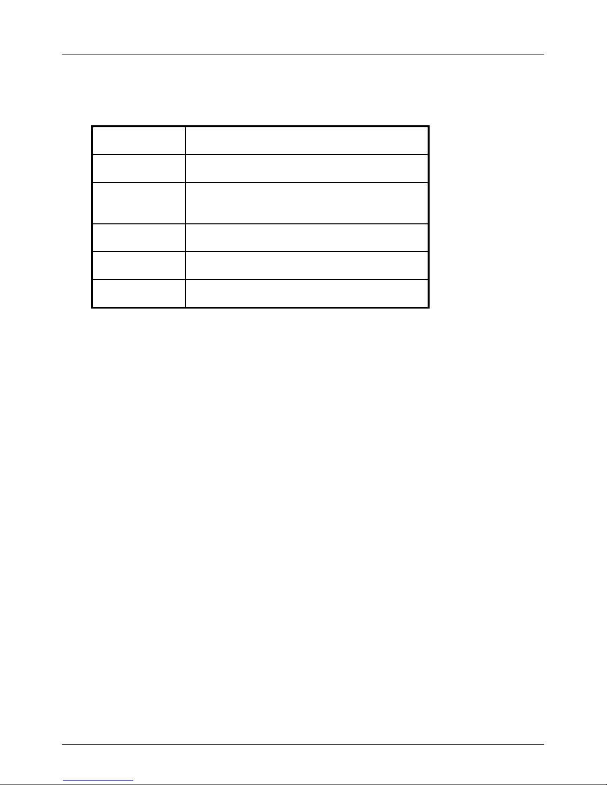
LED indicator light
LED
Display function
LED-UB
Power supply is connected
LED sensor
The sensor is connected and the
measuring voltage is at least 0.25V.
LED rel1
Relay 1 closed
LED rel2
Relay 2 closed
LED rel3
Relay 3 closed
Page 20
Betriebsanleitung/Operating manual
EGS08
20 BD_BE 989 e www.tecsis.de
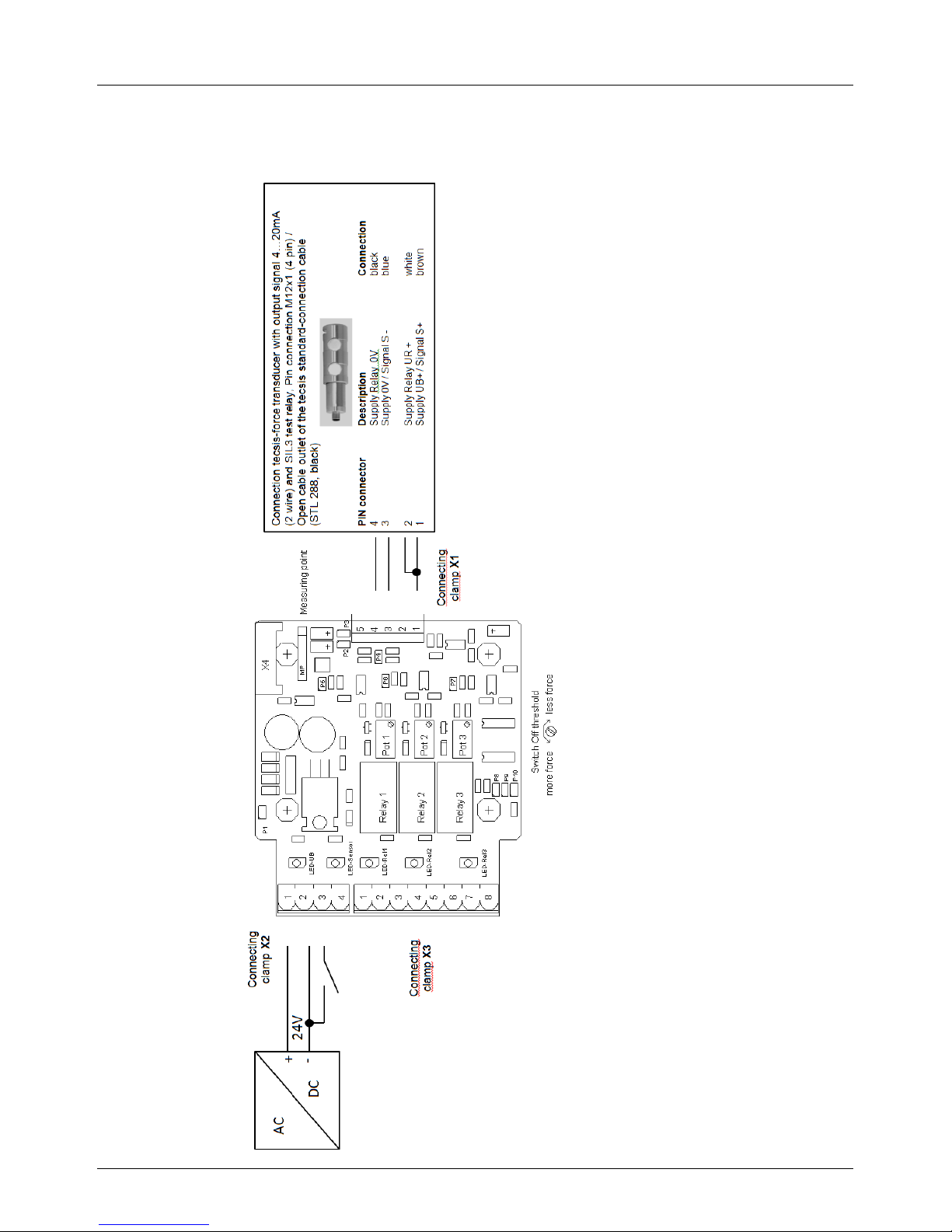
Connection tecsis force transducers with output signal
4…20mA (2 wire) and SIL3 test relay
Page 21
Betriebsanleitung/Operating manual
EGS08
www.tecsis.de BD_BE 989 e 21
When using tecsis force transducer with test relay (4… 20mA – 2 wire for SIL3application), by the connection of the contact clamp 3 at the connection port X2
(activation test relay for signal leap) is released by the factory with the mass
(GND), that at the force receiver after customer's request stopped signal leap.
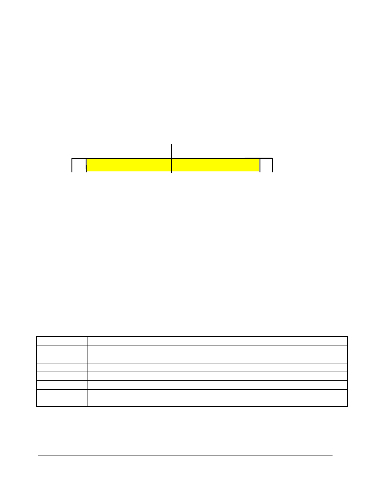
The standard settings of the force transducer with current exit 4… 20 mA for
overload detection e.g. is:
With a firmly stopped signal deviation of 8 mA in each operating condition on
activation of the test relay the point of overload is then exceeded. The upper
measuring range border of 20 mA is not reached however and thus the
examination of the signal deviation is made possible (see in addition for further
information also the data sheets of the appropriate tecsis force transducers).
Connecting clamp X1 for 3 wire
Pin
Description
Note
1
UB
excitation Load Cell 21VDC (internal generate)
2
GND
ground
3
Im
sensor signal 1-9mA or 4-20mA
4
--
--
5
protect
protection of the connection cable against emc
3,8
4
12
20
21
cable break
Short circuit
[mA]
Overload
(125% nominal load)
Page 22
Betriebsanleitung/Operating manual
EGS08
22 BD_BE 989 e www.tecsis.de
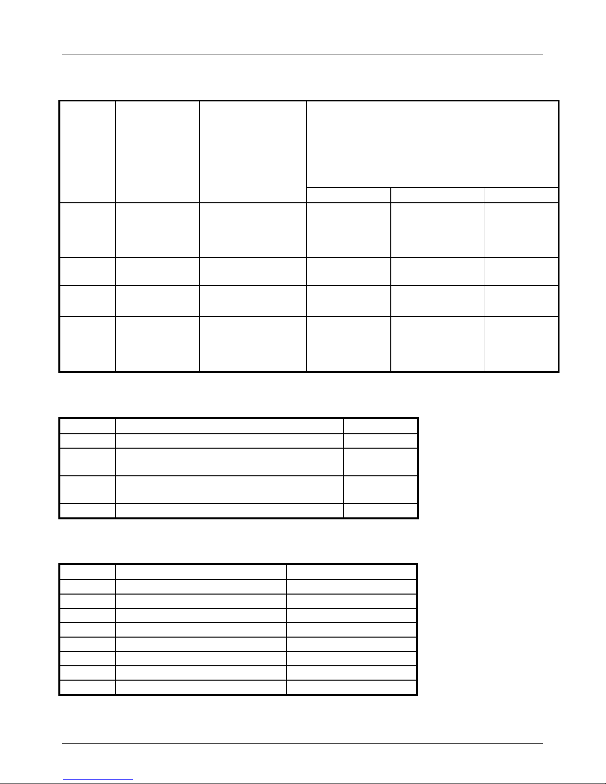
Connecting clamp X1 for 2 wire
Pin
Description
Note
Connection tecsis-force transducer with
output signal 4…20mA (2 wire)
and SIL3 test relay
Pin connection M12x1 (4 pin) /
Open cable outlet of the tecsis standardconnection cable (STL 288, black)
PIN M12x1
Desciption
Connection
1
UB
supply voltage
sensor and relay
21VDC (produced
internally)
1 and
2
supply. UB+ /
signal S+
supply relay.
UR +
brown
white
3
Im
sensor signal 19mA or 4-20mA
3
supply. 0V /
signal S -
blue
4
signal
deviation
supply relay 0 V
4
supply relay
0V
black
5
protect
protection of the
connection cable
against emc
thread M12x1
protect
protect
Connecting clamp X2
Pin.
Description
Controller
1
24 VAC voltage output or +24 VDC suplly
2
24 VAC volatge output or 24 VDC supply
( GND)
3
Activation test relay for signal leap
(with connection the mass (GND))
4
mass
Connecting clamp X3
Pin.
Description
Controller
1
Relay 1, operating contact
2
Relay 1, center contact
POT 1
3
Relay 2, operating contact
4
Relay 2, de-energised conact
5
Relay 2, center contact
POT 2
6
Relay 3, operating contact
7
Relay 3, de-energised conact
8
Relay 3, center contact
POT 3
Page 23

Betriebsanleitung/Operating manual
EGS08
www.tecsis.de BD_BE 989 e 23
3 Technical data
Power supply: 24VDC (-10%/+40%)
Current consumption: max. 100mA (without sensor)
Input to strain gauge sensor: Current input 1-9mA or 4-20mA
Sensor supply: 21V DC
Outputs: 3 Relay outputs (for specification see below)
Load resistance: 360 or 180
Wire broken recognition: Release of relay functions
from 0.7mA signal current at 1-9mA load resistance
from 1.4mA signal current at 4-20mA load resistance
Housing: 80 * 67 * 41 mm³
Fastening of housing: two holes
Diagonal 45 * 89 mm²
Operating temperature: 0°C … 70°C
Protection class IP20
Specifications of the relay RD2N-1U used:
30W 1.25A dc (ohmic)
30W 100V dc (ohmic)
60VA 1.25A ac (ohmic)
60VA 125V ac (ohmic)
20VA 1.25A ac (inductive)
20VA 125V ac (inductive)
Page 24

Betriebsanleitung/Operating manual
EGS08
24 BD_BE 989 e www.tecsis.de
tecsis GmbH
Carl-Legien-Straße 40-44
D-63073 Offenbach am Main
Telefon: +49 69 5806-0
Telefax: +49 69 5806-7788
E-Mail: [email protected]
Internet: www.tecsis.de
 Loading...