

Page 1
| Force | Pressure | Temperature | Switch
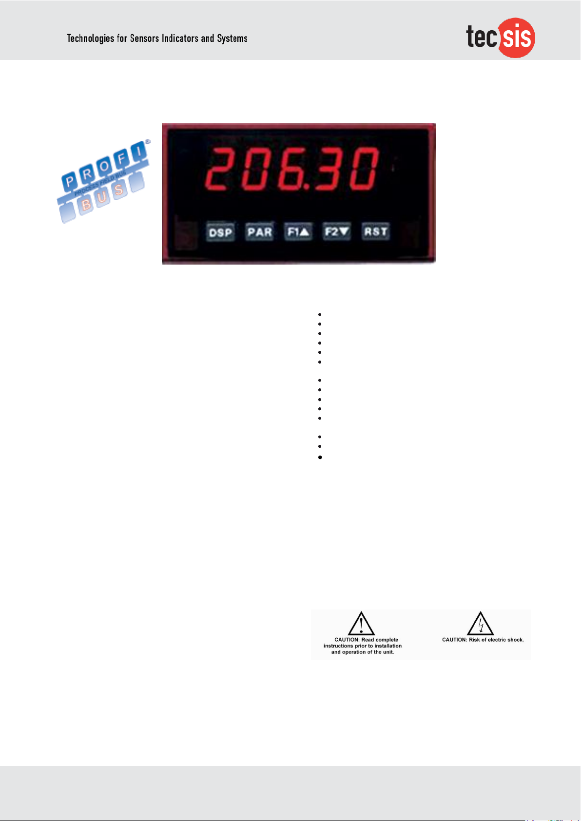
Model no.: E1931X402
2 – channel Digital indicator for strain transducers
GENERAL DESCRIPTION
The E1931X402 Dual Process Input Meter o_ers many features and
performance capabilities to suit a wide range of industrial
applications. Available in two models, AC or DC power, the meter
has the capability to accept two, 4 to 20 mA or 0 to 10 VDC input
signals. Each input signal can be independently scaled and
displayed. In addition, a math function can be performed on the two
signals, C + A + B, C - A - B, C + A - B, AB / C, CA / B, or C (A / B -
1). Any of the three meter values can have Alarms, Comms, and/or a
Retransmitted Analog Output capability by simply adding optional
cards. The optional plug-in output cards allow the opportunity to
con_gure the meter for current applications, while providing easy
upgrades for future needs.
The update rate of the meter is user selectable. This will help in
those applications where a quick response from the meter is of the
utmost importance. The rate can be adjusted from eight selections
with a minimum of 5 updates/second to a maximum of 105
updates/second. The meters employ a bright 0.56" (14.2 mm) red
sunlight readable LED display. The intensity of display can be
adjusted from dark room applications up to sunlight readable,
making it ideal for viewing in bright light applications.
The meters provide a MAX and MIN reading memory with
programmable capture time. The capture time is used to prevent
detection of false max or min readings which may occur during startup or unusual process events. The signal totalizer (integrator) can be
used to compute a time-input product. This can be used to provide a
readout of totalized _ow, calculate service intervals of motors or
pumps, etc. The totalizer can also accumulate batch operations.
The meter has four setpoint outputs, implemented on Plug-in option
cards. The Plug-in cards provide dual FORM-C relays (5A), quad
FORM-A (3A), or either quad sinking or quad sourcing open collector
logic outputs. The setpoint alarms can be con_gured to suit a variety
of control and alarm requirements. Communication and Bus
Capabilities are also available as option cards. The standard output
is in Modbus Protocol. Any of the following option cards, RS232,
RS485, DeviceNet, or Pro_bus can be used with the meter. Readout
values and setpoint alarm values can be controlled through the bus.
Additionally, the meters have a feature that allows a remote
computer to directly control the outputs of the meter.
A linear DC output signal is available as an optional Plug-in card.
The card provides either 20 mA or 10 V signals. The output can be
scaled independent of the input range and can track either the input,
totalizer, max/min readings, or math calculation value. Once the
meters have been initially con_gured, the parameter list may be
locked out from further modi_cation in its entirety or only the setpoint
values can be made accessible. The meters have been speci_cally
designed for harsh industrial environments.
With NEMA 4X/IP65 sealed bezel and extensive testing of noise
e_ects to CE requirements, the meter provides a tough yet reliable
application solution.
tecsis GmbH DE 965_402
Carl-Legien Str. 40
D-63073 Offenbach / Main Sales national Sales international e-Mail: [email protected] p. 1 / 4
Tel.: +49 69 5806-0 Fax: +49 69 5806-170 Fax: +49 69 5806-177 Internet: www.tecsis.de
FEATURES
ACCEPTS TWO 4 - 20 mA OR 0 - 10 VDC INPUT SIGNALS
PROGRAMMABLE A/D CONVERSION RATE, 5 TO 105
READINGS PER SECOND
5-DIGIT 0.56" RED SUNLIGHT READABLE DISPLAY
VARIABLE INTENSITY DISPLAY
LINEARIZATION/SQUARE ROOT EXTRACTION INPUT
RANGE
PROGRAMMABLE FUNCTION KEYS/USER INPUTS
9 DIGIT TOTALIZER (INTEGRATOR) WITH BATCHING
OPTIONAL CUSTOM UNITS OVERLAY W/BACKLIGHT
FOUR SETPOINT ALARM OUTPUTS (W/OPTION CARD)
COMMUNICATION AND BUS CAPABILITIES (W/OPTION
CARD)
RETRANSMITTED ANALOG OUTPUT (W/OPTION CARD)
NEMA 4X/IP65 SEALED FRONT BEZEL
PC SOFTWARE AVAILABLE FOR METER CONFIGURATION
SAFETY SUMMARY
All safety related regulations, local codes and instructions that
appear in this literature or on equipment must be observed to
ensure personal safety and to prevent damage to either the
instrument or equipment connected to it. If equipment is used in a
manner not speci_ed by the manufacturer, the protection
provided by the equipment may be impaired. Do not use this unit
to directly command motors, valves, or other actuators
not equipped with safeguards. To do so can be potentially harmful
to persons or equipment in the event of a fault to the unit.
Page 2
Technical data
1. DISPLAY :
5 digit, 0.56" (14.2 mm) variable intensity red sunlight readable
(-19999 to 99999)
2. POWER :
AC Versions:
AC Power: 85 to 250 VAC, 50/60 Hz, 21 VA
Isolation: 2300 Vrms for 1 min. to all inputs and outputs.
DC Versions: (Derate operating temperature to 40° C if three plug-in option
cards are installed.)
DC Power: 18 to 36 VDC, 13 W
AC Power: 24 VAC, ± 10%, 50/60 Hz, 16 VA
Isolation: 500 Vrms for 1 min. to all inputs and outputs (50 V working).
Must use a Class 2 or SELV rated power supply
3. ANNUNCIATORS :
A - Programmable Display
B - Programmable Display
C - Programmable Display
SP1 - Setpoint alarm 1 is active
SP2 - Setpoint alarm 2 is active
SP3 - Setpoint alarm 3 is active
SP4 - Setpoint alarm 4 is active
Units Label - Optional units label backlight
4. KEYPAD : 3 programmable function keys, 5 keys total
5. A/D CONVERTER : 16 bit resolution
6. UPDATE RATES :
A/D conversion rate: Adjustable 5.3 to 105 readings/sec.
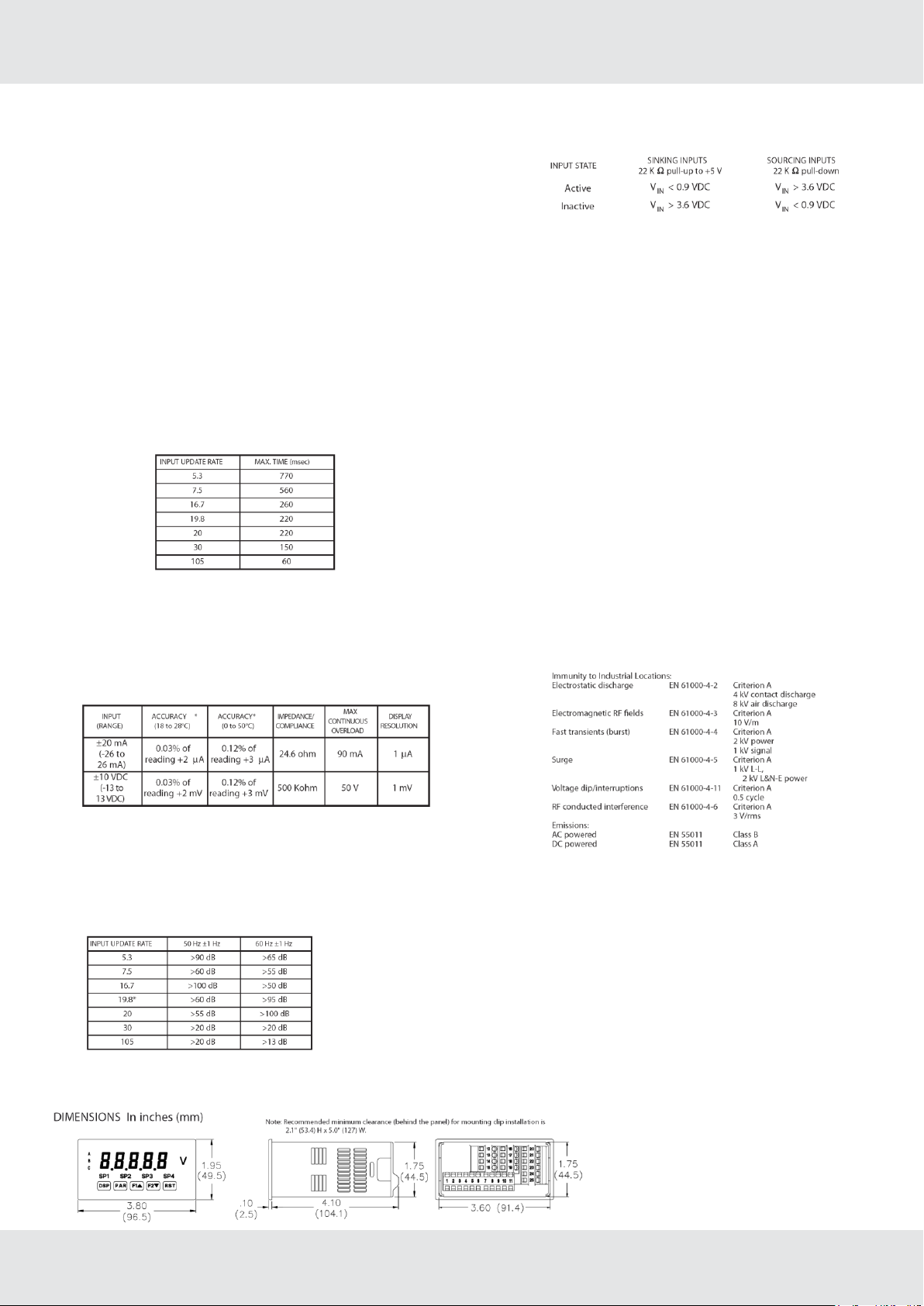
Step response: (to within 99% of _nal readout value with digital _lter disabled)
Display update rate: adjustable 1 to 20 readings/sec.
Setpoint output on/o_ delay time: 0 to 3275 sec.
Analog output update rate: 0 to 10 sec
Max./Min. capture delay time: 0 to 3275 sec.
7. DISPLAY MESSAGES :
“OLOL” - Appears when measurement exceeds + signal range.
“ULUL” - Appears when measurement exceeds - signal range
“. . . .” - Appears when display values exceed + display range.
“- . . .” - Appears when display values exceed - display range.
8. SENSOR INPUTS :
* After 20 minute warm-up. Accuracy is speci_ed in two ways: Accuracy over
an 18 to 28°C and 10 to 75% RH environment; and accuracy over a 0 to 50°C
and 0 to 85% RH (non-condensing environment). Accuracy over the 0 to
50°C range includes the temperature coe_cient e_ect of the meter.
9. EXCITATION POWER :
Transmitter Power: 18 VDC, ±20%, unregulated, 70 mA max. per
input channel.
10. LOW FREQUENCY NOISE REJECTION :
Normal Mode: (digital _lter o_)
*Note: 19.8 Hz Input Rate provides best rate
performance and simultaneous 50/60 Hz rejection.
Common Mode: >100 dB @ 50/60 ±1 Hz (19.8 or 20 Input Rate)
DE 965_402
p. 2 / 4
11. USER INPUTS :
Three programmable user inputs
Max. Continuous Input: 30 VDC
Isolation To Sensor Input A Common: 500 Vrms for 1 min;
Working Voltage: 50 V
Isolation To Sensor Input B Common: Not isolated.
Response Time: 20 msec. max.
Logic State: Jumper selectable for sink/source logic
12. TOTALIZER :
Function:
Time Base: second, minute, hour, or day
Batch: Can accumulate (gate) input display from a user input
Time Accuracy: 0.01% typical
Decimal Point: 0 to 0.0000
Scale Factor: 0.001 to 65.000
Low Signal Cut-out: -19,999 to 99,999
Total: 9 digits, display alternates between high order and low order readouts
13. CUSTOM LINEARIZATION :
Data Point Pairs: Selectable from 2 to 16
Display Range: -19,999 to 99,999
Decimal Point: 0 to 0.0000
14. MEMORY :
Nonvolatile memory retains all programmable parameters and display values.
15. CERTIFICATIONS AND COMPLIANCES : SAFETY
UL Recognized Component, File #E179259, UL6101A-1, CSA C22.2 No.
1010-1
Recognized to U.S. and Canadian requirements under the Component
Recognition Program of Underwriters Laboratories, Inc.
UL Listed, File #E137808, UL508, CSA C22.2 No. 14-M95
LISTED by Und. Lab. Inc. to U.S. and Canadian safety standards
Type 4X Enclosure rating (Face only), UL50
IECEE CB Scheme Test Certi_cate #US/8843A/UL
CB Scheme Test Report #04ME11209-20041018
Issued by Underwriters Laboratories, Inc.
IEC 61010-1, EN 61010-1: Safety requirements for electrical
equipment for measurement, control, and laboratory use, Part 1.
IP65 Enclosure rating (Face only), IEC 529
IP20 Enclosure rating (Rear of unit), IEC 529
Torque: 4.5 inch-lbs (0.51 N-m) max.
15. CERTIFICATIONS AND COMPLIANCES (Cont’d) :
ELECTROMAGNETIC COMPATIBILITY
Emissions and Immunity to EN 61326: Electrical Equipment for
Measurement, Control and Laboratory use.
Notes:
1. Criterion A: Normal operation within speci_ed limits.
2. Criterion B: Temporary loss of performance from which the unit selfrecovers.
Refer to EMC Installation Guidelines section of the bulletin for additional
information.
16. ENVIRONMENTAL CONDITIONS :
Operating Temperature Range: 0 to 50°C (0 to 45°C with all three plug-in
option cards installed)
Storage Temperature Range: -40 to 60°C
Operating and Storage Humidity: 0 to 85% max. RH non-condensing
Altitude: Up to 2000 meters
17. CONNECTIONS :
High compression cage-clamp terminal block
Wire Strip Length: 0.3" (7.5 mm)
Wire Gage: 30-14 AWG copper wire
Torque: 4.5 inch-lbs (0.51 N-m) max.
18. CONSTRUCTION :
This unit is rated for NEMA 4X/IP65 outdoor use.
IP20 Touch safe. Installation Category II, Pollution Degree 2. One piece
bezel/case. Flame resistant. Synthetic rubber keypad. Panel gasket and
mounting clip included.
19. WEIGHT : 10.4 oz. (295 g)
Page 3
2. Installing the meter
Installation
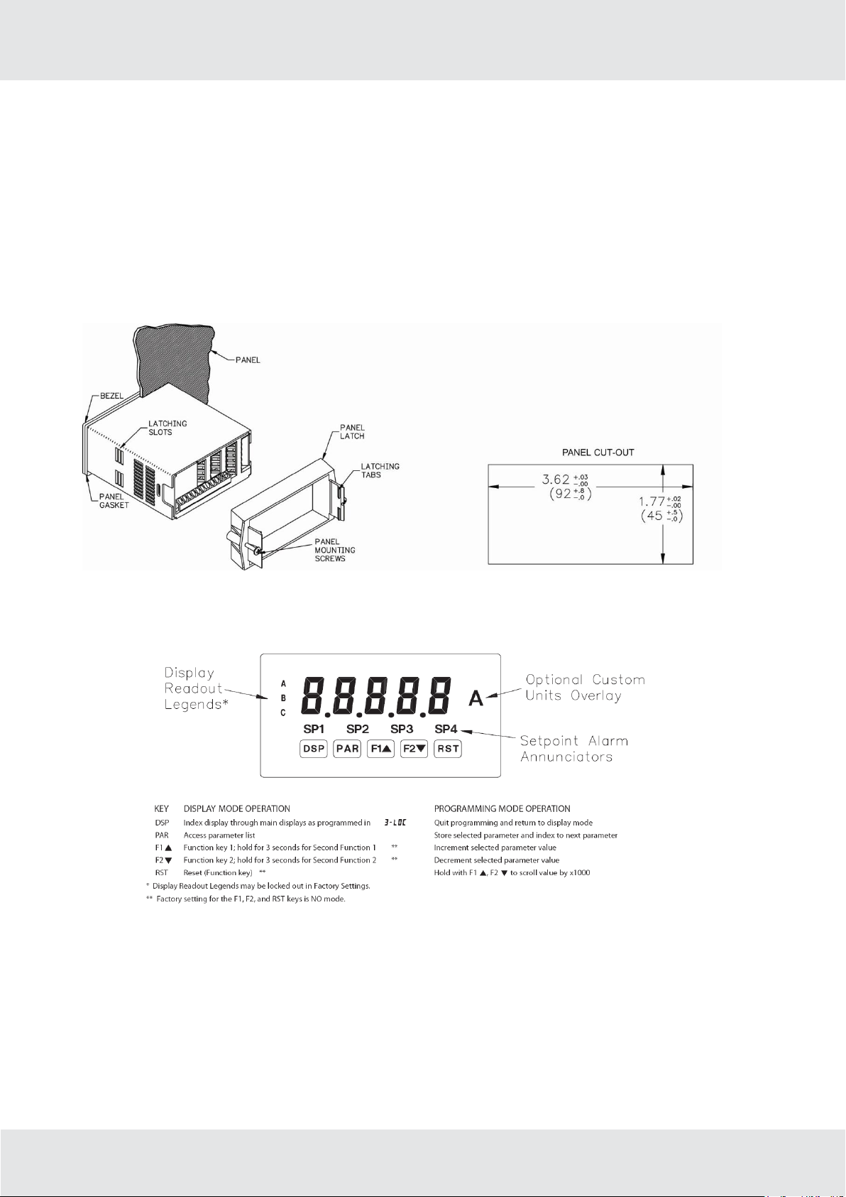
The meter meets NEMA 4X/IP65 requirements when properly
installed. The unit is intended to be mounted into an enclosed panel.
Prepare the panel cutout to the dimensions shown. Remove the
panel latch from the unit. Slide the panel gasket over the rear of the
unit to the back of the bezel. The unit should be installed fully
assembled. Insert the unit into the panel cutout. While holding the
unit in place, push the panel latch over the rear of the unit so that the
tabs of the panel latch engage in the slots on the case. The panel
latch should be engaged in the farthest forward slot possible. To
achieve a proper seal, tighten the latch screws evenly until the unit is
snug in the panel (Torque to approximately 7 in-lbs [79N-cm]). Do
not over-tighten the screws.
3. Reviewing the front buttons and display
Installation Environment
The unit should be installed in a location that does not exceed the
maximum operating temperature and provides good air
circulation. Placing the unit near devices that generate excessive
heat should be avoided. The bezel should be cleaned only with a
soft cloth and neutral soap product.
Do NOT use solvents. Continuous exposure to direct sunlight may
accelerate the aging process of the bezel. Do not use tools of any
kind (screwdrivers, pens, pencils, etc.) to operate the keypad of
the unit.
DE 965_402
p. 3 / 4
Page 4

4. Accessories
UNITS LABEL KIT
Each meter has units indicator with backlighting that can be
customized using the Units Label Kit. The backlight is controlled in
the programming.
5. Optional plug-in output cards
The E1931X402 series meters can be _tted with up to three optional
plugin cards. The details for each plug-in card can be reviewed in the
speci_cation section below. Only one card from each function type
can be installed at one time. The function types include Setpoint
Alarms, Communications and Analog Output. The plug-in cards can
be installed initially or at a later date.
Communication cards
A variety of communication protocols are available for the
E1931X402 series. Only one of these cards can be installed at a
time.
Note: For Modbuscommunications use RS485 Communications
Output Card and con_gure communication ( ) parameter for
Modbus.
- RS485 Serial (Terminal Block)
- DeviceNet
- RS232 Serial (Terminal Block)
- RS485 Serial (Dual RJ11 Connector)
- Proibus-DP
- RS232 Serial (9 Pin D Connector)
SERIAL COMMUNICATIONS CARD
Type: RS485 or RS232
Isolation To Sensor & User Input Commons : 500 Vrms for 1 min.
Working Voltage: 50 V. Not Isolated from all other commons.
Baud : 300 to 38,400
Data: 7/8 bits
Parity : no, odd or even
Bus Address : Selectable 0 to 99 (RLC Protocol), or 1 to 247
(Modbus Protocol), Max. 32 meters per line (RS485)
Transmit Delay : Selectable for 0 to 0.250 sec (+2 msec min)
DEVICENET™ CARD
Compatibility : Group 2 Server Only, not UCMM capable
Baud Rates : 125 Kbaud, 250 Kbaud, and 500 Kbaud
Bus Interface : Phillips 82C250 or equivalent with MIS wiring
protection per DeviceNet™ Volume I Section 10.2.2.
Node Isolation : Bus powered, isolated node
Host Isolation : 500 Vrms for 1 minute (50 V working) between
DeviceNet™ and meter input common.
PROFIBUS-DP CARD
Fieldbus Type: Pro_bus-DP as per EN 50170, implemented with
Siemens SPC3 ASIC
Conformance: PNO Certi_ed Pro_bus-DP Slave Device
Baud Rates: Automatic baud rate detection in the range 9.6 Kbaud
to 12 Mbaud
Station Address: 0 to 126, set by the master over the network.
Address stored in non-volatile memory.
Connection: 9-pin Female D-Sub connector
Network Isolation: 500 Vrms for 1 minute (50 V working) between
Proibus network and sensor and user input commons. Not isolated
from all other commons.
SETPOINT CARDS
The E1931X402 series has 4 available setpoint alarm output plug-in
cards. Only one of these cards can be installed at a time. (Logic
state of the outputs can be reversed in the programming.) These
plug-in cards include:
- Dual Relay, FORM-C, Normally open & closed
- Quad Relay, FORM-A, Normally open only
- Isolated quad sinking NPN open collector
- Isolated quad sourcing PNP open collector
DUAL RELAY CARD
Type : Two FORM-C relays
Isolation To Sensor & User Input Commons : 2000 Vrms for 1 min.
Working Voltage: 240 Vrms
DE 965_402
p. 4 / 4
Contact Rating :
One Relay Energized: 5 amps @ 120/240 VAC or 28 VDC
(resistive load),
1/8 HP @120 VAC, inductive load
Total current with both relays energized not to exceed 5 amps
Life Expectancy : 100 K cycles min. at full load rating. External
RC snubber extends relay life for operation with inductive loads
QUAD RELAY CARD
Type : Four FORM-A relays
Isolation To Sensor & User Input Commons : 2300 Vrms for 1 min.
Working Voltage: 250 Vrms
Contact Rating :
One Relay Energized: 3 amps @ 240 VAC or 30 VDC (resistive
load), 1/10
HP @120 VAC, inductive load
Total current with all four relays energized not to exceed 4 amps
Life Expectancy : 100 K cycles min. at full load rating. External
RC snubber extends relay life for operation with inductive loads
QUAD SINKING OPEN COLLECTOR CARD
Type : Four isolated sinking NPN transistors.
Isolation To Sensor & User Input Commons : 500 Vrms for
1 min.
Working Voltage: 50 V. Not Isolated from all other commons.
Rating : 100 mA max @ V SAT = 0.7 V max. V MAX = 30 V
QUAD SOURCING OPEN COLLECTOR CARD
Type : Four isolated sourcing PNP transistors.
Isolation To Sensor & User Input Commons : 500 Vrms for 1 min.
Working Voltage: 50 V. Not Isolated from all other commons.
Rating : Internal supply: 24 VDC ± 10%, 30 mA max. total
External supply: 30 VDC max., 100 mA max. each output
ALL FOUR SETPOINT CARDS
Response Time : See update rates step response specification;
add 6 msec (typical) for relay card
LINEAR DC OUTPUT
Either a 0(4)-20 mA or 0-10 V retransmitted linear DC output is
available from the analog output plug-in card. The programmable
output low and high scaling can be based on various display
values. Reverse slope output is possible
by reversing the scaling point positions.
- Retransmitted Analog Output Card
ANALOG OUTPUT CARD
Types : 0 to 20 mA, 4 to 20 mA or 0 to 10 VDC
Isolation To Sensor & User Input Commons : 500 Vrms for 1 min.
Working Voltage: 50 V. Not Isolated from all other commons.
Accuracy : 0.17% of FS (18 to 28°C); 0.4% of FS (0 to 50°C)
Resolution : 1/3500
Compliance: 10 VDC: 10 K Ω load min., 20 mA: 500 Ω load max.
Update time: See update rates step response speci_cation
Type Order No.
Serial communication card RS 485 / RS 422 A5753X002001
Serial communication card RS 232 A5753X002002
Analogue output card A5753X002005
Dual relay card A5753X002006
Quad relay card A5753X002007
Quad sinking open collector card (4 x NPN) A5753X002008
Quad sourcig open collector card (4 x PNP) A5753X002009
Housing IP65 for 96x46 Informators EZM45X001006
 Loading...