

Page 1
P. 1
| Tecshow Navi gator Split 8
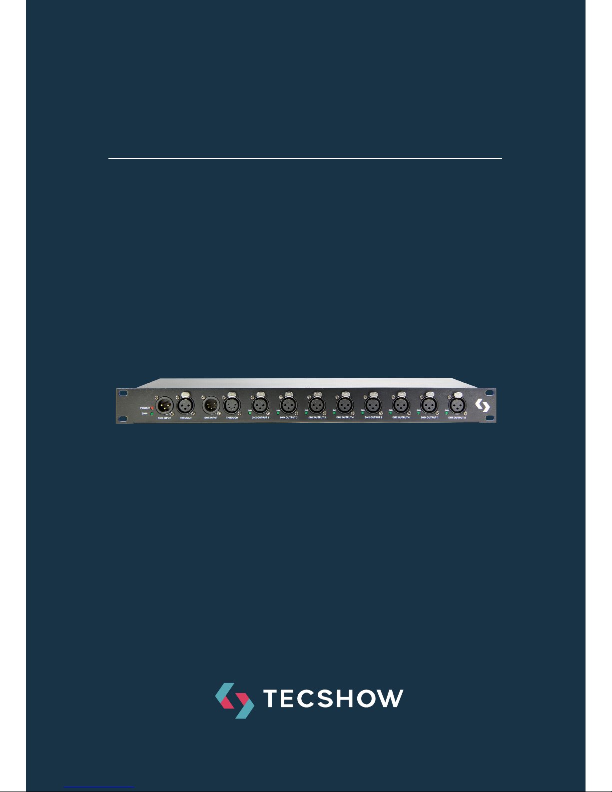
NAVIGATOR SPLIT 8
8-way DMX splitter
USER MANUAL / MANUAL DE USUARIO
PLEASE READ THE INSTRUCTIONS CAREFULLY BEFORE USE
POR FAVOR LEA LAS INSTRUCCIÓNES ANTES DE USAR
Page 2

P. 2
Tecshow Navi gator Split 8 |
Navigator Split 8
8-way DMX splitter
Navigator Split 8 is an 8-way DMX splitter that
eectively reduces signal loss in extended range
transmissions. With its multiple input/output
options, Navigator Split 8 is easy to integrate into
any project. It also has two inputs (XLR-3 and XLR-
5) and two thru outputs (XLR-3 and XLR-5), apart
from its 8 optically isolated outputs with XLR-3 DMX
connectors.
Specications
Features
• DMX-512 signal
• Optical isolation
• DMX signal indicator for input and each of the 8
outputs.
• Optimized signal quality for extended range
transmissions
• Electrical isolation between inputs and outputs
Connectors
• 8 XLR-3 DMX outputs
• 1 XLR-3 DMX input
• 1 XLR-5 DMX input
• 1 XLR-3 DMX thru output
• 1 XLR-5 DMX thru output
Physical
• Dimensions: 483x136x46 mm. / 19x5.3x1.8 in.
• Weight: 2.6 Kg. / 5.7 Lbs.
1. OVERVIEW
English version
Page 3
P. 3
| Tecshow Navi gator Split 8
English version
2. WARNING
For your own safety, please read this
user manual carefully before your initial start-up!
Unpacking Instructions
Immediately upon receiving this product, carefully unpack the carton and check the contents to
ensure that all parts are present, and have been
received in good condition. Notify the dealer immediately and retain packing material for inspection
if any parts appear damaged from shipping or the
carton itself shows signs of mishandling. Save the
carton and all packing materials. In the event that a
xture must be returned to the factory, it is important that the xture be returned in the original
factory box and packing.
Your shipment includes:
• Navigator Split 8 with IEC powercable 1,5m
• User manual
LED Expected Lifespan
LEDs gradually decline in brightness over time.
HEAT is the dominant factor that leads to the acceleration of this decline. Packaged in clusters, LEDs
exhibit higher operating temperatures than in ideal
or singular optimum conditions. For this reason
when all color LEDs are used at their fullest intensity, life of the LEDs is signicantly reduced. It is
estimated that a viable lifespan of 40,000 to 50,000
hours will be achieved under normal operational
conditions. If improving on this lifespan expectancy
is of a higher priority, place care in providing for
lower operational temperatures. This may include
climatic-environmental and the reduction of overall
projection intensity.
Keep this device away from rain and
moisture! indoor use only!
Safety Instructions
Every person involved with the installation, operation and maintenance of this device has to:
• be qualied
• follow the instructions of this manual
Be careful with your operations. With
a dangerous voltage you can suer a
dangerous electric shock when touching the wires!
Before your initial start-up, please make sure that
there is no damage caused by transportation.
Should there be any, consult your dealer and do not
use the device.
To maintain perfect condition and to ensure a safe
operation, it is absolutely necessary for the user to
follow the safety instructions and warning notes
written in this manual.
Please consider that damages caused by manual modications to the device are not subject to
warranty. This device contains no user-serviceable
parts. Refer servicing to qualied technicians only.
Important
The manufacturer will not accept liability for any
resulting damages caused by the nonobservance
of this manual or any unauthorized modication to
the device.
• Never let the power-cord come into contact
with other cables! Handle the power-cord and
all connections with the mains with particular
caution!
• Never remove warning or informative labels
from the unit.
• Never use anything to cover the ground contact.
• Never look directly into the light source.
• Never leave any cables lying around.
• Never use the device during thunderstorms,
unplug the device immediately.
Page 4

P. 4
Tecshow Navi gator Split 8 |
English version
• Never leave various parts of the packaging
(plastic bags, polystyrene foam, nails, etc.)
within children’s reach, as they are potential
sources of danger.
• Do not insert objects into air vents.
• Do not open the device and do not modify the
device.
• Do not connect this device to a dimmerpack.
• Do not shake the device. Avoid brute force
when installing or operating the device.
• Do not switch the device on and o in short
intervals, as this would reduce the system’s life.
• Do not touch the device’s housing bare-handed
during its operation (housing becomes hot).
• Only use device indoor, avoid contact with wa-
ter or other liquids.
• Only operate the device aer having familiar-
ized with its functions.
• Only install the device with the hanging-bracket.
• Avoid ames and do not put close to ammable
liquids or gases.
• Always keep case closed while operating.
• Always allow free air space of at least 50 cm
around the unit for ventilation.
• Always disconnect power from the mains, when
device is not used or before cleaning! Only handle the power-cord by the plug. Never pull out
the plug by tugging the power-cord.
• Make sure that the device is not exposed to
extreme heat, moisture or dust.
• Make sure that the available voltage is not higher than stated on the rear panel.
• Make sure that the power-cord is never crimped
or damaged. Check the device and the powercord from time to time.
• Make sure that no side forces can impact on the
truss system.
• The cable insert or the female part in the device
must never be strained. There must always
be suicient cable to the device. Otherwise,
the cable may be damaged which may lead to
deadly electrical shocks.
• If the external cable is damaged, it has to be
replaced by a qualied technician.
• If the lens is obviously damaged, it has to be
replaced. So that its functions are not impaired,
due to cracks or deep scratches.
• If device is dropped or struck, disconnect mains
power supply immediately. Have a qualied
engineer inspect for safety before operating.
• If the device has been exposed to drastic tem-
perature uctuation (e.g. aer transportation),
do not switch it on immediately. The arising
condensation water might damage your device. Leave the device switched o until it has
reached room temperature.
• If your Showtec device fails to work properly,
discontinue use immediately. Pack the unit
securely (preferably in the original packing
material), and return it to your Showtec dealer
for service.
• For adult use only. The device must be installed
out of the reach of children. Never leave the unit
running unattended.
• For replacement use fuses of same type and
rating only.
• The user is responsible for correct positioning
and operating of the Navigator Split 8. The
manufacturer will not accept liability for damages caused by the misuse or incorrect installation of this device.
• This device falls under protection class I. There-
fore it is essential to connect the yellow/green
conductor to earth.
• For replacement use fuses of same type and
rating only.
• Repairs, servicing and electric connection must
be carried out by a qualied technician.
• WARRANTY: Till one year aer date of purchase.
Eyedamages. Avoid looking directly
into the light source (meant especially
for epileptics).
Page 5

P. 5
| Tecshow Navi gator Split 8
English version
3. OPERATING DETERMINATIONS
• This device is not designed for permanent oper-
ation. Consistent operation breaks will ensure
that the device will serve you for a long time
without defects.
• The minimum distance between light-output
and the illuminated surface must be more than
0.5 meter.
• The maximum ambient temperature ta = 45°C
must never be exceeded.
• The relative humidity must not exceed 50 %
with an ambient temperature of 45° C.
• If this device is operated in any other way, than
the one described in this manual, the product
may suer damages and the warranty becomes
void.
• Any other operation may lead to dangers like
short-circuit, burns, electric shock, crash etc.
You endanger your own safety and the safety of
others!
Rigging
Please follow the European and national guidelines
concerning rigging, trussing and all other safety
issues.
Do not attempt the installation yourself! Always
let the installation be carried out by an authorized dealer!
Procedure
• If the Navigator Split 8 is lowered from the ceil-
ing or high joists, professional trussing systems
have to be used.
• Use a clamp to mount the Navigator Split 8,
with the mounting-bracket, to the trussing
system.
• The Navigator Split 8 must never be xed
swinging freely in the room.
• The installation must always be secured with a
safety attachment, e.g. an appropriate safety
net or safety-cable.
• When rigging, derigging or servicing the de-
vice, always make sure, that the area below the
installation place is blocked and staying in the
area is forbidden.
Improper installation can cause serious damage
to people and property!
Connection with the mains
Connect the device to the mains with the power-plug. Always pay attention, that the right color
cable is connected to the right place.
Make sure that the device is always connected properly to the earth!
Claims
The client has the obligation to check the delivered
goods immediately upon delivery for any shortcomings and/or visible defects, or perform this
check aer our announcement that the goods are
at their disposal. Damage incurred in shipping is the
responsibility of the shipper; therefore the damage must be reported to the carrier upon receipt
of merchandise. It is the customer's responsibility
to notify and submit claims with the shipper in
the event that a xture is damaged due to shipping. Transportation damage has to be reported
to us within one day aer receipt of the delivery.
Any return shipment has to be made post-paid at
all times. Return shipments must be accompanied with a letter dening the reason for return
shipment. Non-prepaid return shipments will be
refused, unless otherwise agreed in writing. Com-
Int. EU Cable UK Cable US Cable Pin
L Brown Red Yellow/
Copper
Fase
N Blue Black Silver Nul
Yellow/
Green
Green Green Earth
Page 6
P. 6
Tecshow Navi gator Split 8 |
English version
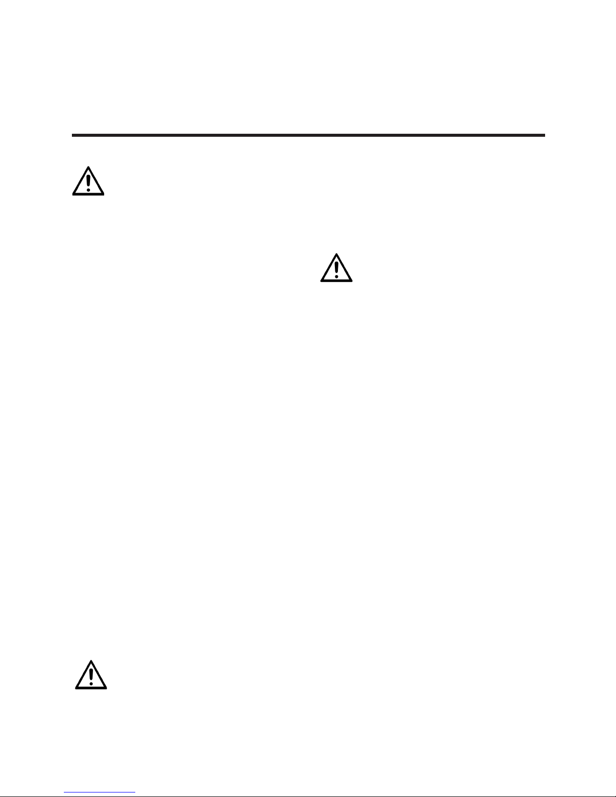
4. THE DEVICE
1. Power LED
2. DMX Signal LED
3. DMX Input 3-pin
4. DMX Link 3-pin
5. DMX Input 5-pin
6. DMX Link 5-pin
7. DMX Isolated Output 1 3-pin
8. DMX Isolated Output 2 3-pin
9. DMX Isolated Output 3 3-pin
10. DMX Isolated Output 4 3-pin
11. DMX Isolated Output 5 3-pin
12. DMX Isolated Output 6 3-pin
13. DMX Isolated Output 7 3-pin
14. DMX Isolated Output 8 3-pin
15. Powercable
16. 13mm mounting location
plaints against us must be made known in writing
or by fax within 10 working days aer receipt of the
invoice. Aer this period complaints will not be handled anymore. Complaints will only then be consid-
ered if the client has so far complied with all parts
of the agreement, regardless of the agreement of
which the obligation is resulting.
15 16
1 2 3 4 5 6 7 8 9 10 11 12 13 14
Page 7

P. 7
| Tecshow Navi gator Split 8
English version
5. INSTALLATION
6. SET UP AND OPERATION
Remove all packing materials from the Navigator
Split 8. Check that all foam and plastic padding is
removed. Connect all cables.
Do not supply power before the whole system is set up and connected properly. Always
disconnect from electric mains power supply
before cleaning or servicing. Damages caused by
non-observance are not subject to warranty.
Before plugging the unit in, always make sure that
the power supply matches the product specication voltage. Do not attempt to operate a 120V
specication product on 230V power, or vice versa.
Remove all packing materials from the Navigator
Split 8. Check that all foam and plastic padding is
removed.
You will need a serial data link to run light shows
of one or more xtures using a DMX-512 controller or to run synchronized shows on two or more
xtures set to a master/slave operating mode. The
combined number of channels required by all the
xtures on a serial data link determines the number
of xtures the data link can support.
DMX Setup Example
1. Fasten the movingheads onto rm trussing.
Leave at least 0,5 meter on all sides for air circulation.
2. Always use a safety cable (ordercode 70140 /
70141).
3. Use a 3-p XLR cable to connect the moving-
heads and other devices.
4. Link the units as shown, Connect a DMX signal
cable from the DMX controller's DMX "out"
Page 8
P. 8
Tecshow Navi gator Split 8 |
English version
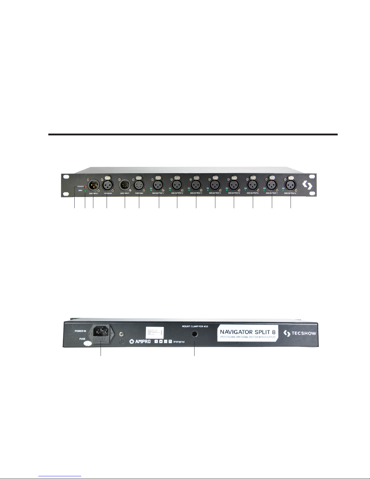
1. Ground
2. Signal (-)
3. Signal (+)
1. Ground
2. Signal (-)
3. Signal (+)
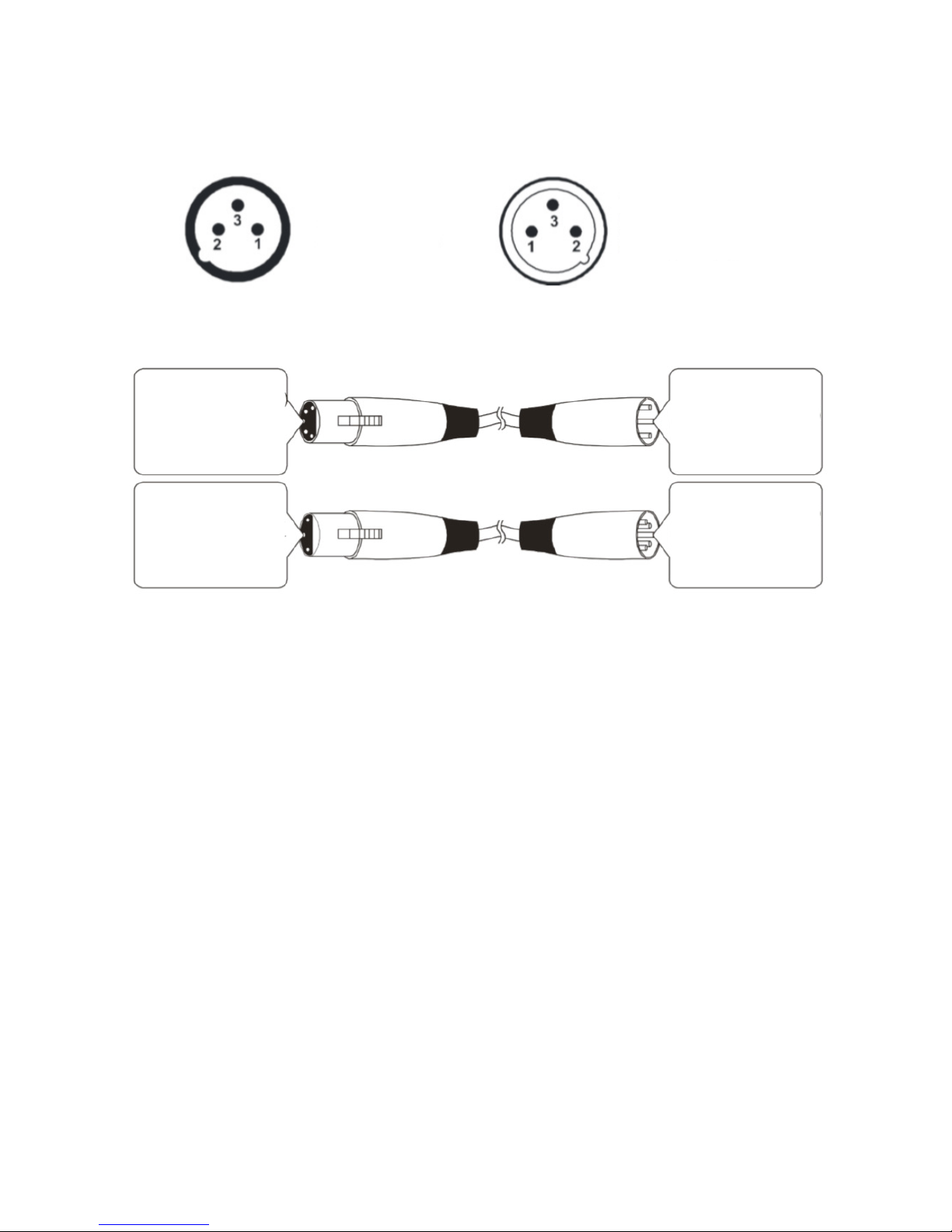
The transformation of the controller line of 3 pins and 5 pins (plug and socket)
5-Pins canon (socket)
Pin 1: GND (screen)
Pin 2: Signal (-)
Pin 3: Signal (+)
Pin 4: N/C
Pin 5: N/C
5-Pins canon (plug)
Pin 1: GND (screen)
Pin 2: Signal (-)
Pin 3: Signal (+)
Pin 4: N/C
Pin 5: N/C
3-Pins canon (socket)
Pin 1: GND (screen)
Pin 2: Signal (-)
Pin 3: Signal (+)
3-Pins canon (plug)
Pin 1: GND (screen)
Pin 2: Signal (-)
Pin 3: Signal (+)
socket to the rst Navigator Split 8 "in" socket.
Connect another DMX signal cable from the rst
Navigator Split 8 DMX "out" socket to the rst
unit's "in" socket. Repeat this process to link
the second, third, and fourth units.
5. Supply electric power: Plug electric mains
power cords into each unit's IEC socket, then
plug the other end of the mains power cord into
proper electric power supply sockets, starting
with the rst unit. Do not supply power before
the whole system is set up and connected
properly.
Page 9

P. 9
| Tecshow Navi gator Split 8
English version
Multiple Movingheads DMX Set Up
Note: Link all cables before connecting electric
power.
Controlling
Aer having addressed all the xtures, you may
now start operating these via your lighting controller. If there is no data received at the DMX-input, the
problem may be:
• The XLR cable from the controller is not connected with the input of the rst xture.
• The controller is switched o or defective, the
cable or connector is detective, or the signal
wires are swapped in the input connector.
Note: It’s necessary to insert a XLR termination
plug (with 120 Ohm) in the last xture in order to
ensure proper transmission on the DMX data link.
Page 10

P. 1 0
Tecshow Navi gator Split 8 |
7. FIXTURE LINKING
You will need a serial data link to run light shows
of one or more xtures using a DMX-512 controller or to run synchronized shows on two or more
xtures set to a master/slave operating mode. The
combined number of channels required by all the
xtures on a serial data link determines the number
of xtures the data link can support.
Important: Fixtures on a serial data link must be
daisy chained in one single line. To comply with the
EIA-485 standard no more than 30 devices should
be connected on one data link. Connecting more
than 30 xtures on one serial data link without the
use of a DMX optically isolated splitter may result in
deterioration of the digital DMX signal.
Maximum recommended DMX data link distance:
100 meters Maximum recommended number of
movingheads on a single DMX data link: 32 xtures.
Data Cabling
To link xtures together you must obtain data
cables. You can purchase DAP Audio certied DMX
cables directly from a dealer/distributor or construct your own cable. If you choose to create your
own cable please use data-grade cables that can
carry a high quality signal and are less prone to
electromagnetic interference.
DAP Audio Certied DMX Data Cables
• DAP Audio cable for allround use. bal. XLR/M
3 p. > XLR/F 3 p. Ordercode FL01150 (1,5m.),
FL013 (3m.), FL016 (6m.), FL0110 (10m.), FL0115
(15m.), FL0120 (20m.).
• DAP Audio cable for the demanding user with
exceptional audio-qualities and connector
made by Neutrik®. Ordercode FL71150 (1,5m.),
FL713 (3m.), FL716 (6m.), FL7110 (10m.).
English version
Page 11

P. 11
| Tecshow Navi gator Split 8
8. MAINTENANCE
The Navigator Split 8 requires almost no maintenance. However, you should keep the unit clean.
Otherwise, the xture’s light-output will be signicantly reduced. Disconnect the mains power
supply, and then wipe the cover with a damp cloth.
Do not immerse in liquid. Wipe lens clean with
glass cleaner and a so cloth. Do not use alcohol or
solvents. Keep connections clean. Disconnect electric power, and then wipe the connections with a
damp cloth. Make sure connections are thoroughly
dry before linking equipment or supplying electric
power.
The operator has to make sure that safety-relating and machine-technical installations are to be
inspected by an expert aer every four years in the
course of an acceptance test. The operator has to
make sure that safety-relating and machine-technical installations are to be inspected by a skilled
person once a year.
The following points have to be considered during
the inspection:
1. All screws used for installing the device or parts
of the device have to be tightly connected and
must not be corroded.
2. There may not be any deformations on hous-
ings, xations and installation spots.
3. Mechanically moving parts like axles, eyes and
others may not show any traces of wearing.
4. The electric power supply cables must not
show any damages or material fatigue.
Replacing a Fuse
Power surges, short-circuit or inappropriate electrical power supply may cause a fuse to burn out.
If the fuse burns out, the product will not function
whatsoever. If this happens, follow the directions
below to do so.
1. Unplug the unit from electric power source.
2. Insert a at-head screwdriver into a slot in the
fuse cover. Turn the screwdriver to the le,
at the same time gently push a bit (Turn and
Push). The fuse will come out.
3. Remove the used fuse. If brown or unclear, it is
burned out.
4. Insert the replacement fuse into the holder
where the old fuse was. Reinsert the fuse cover.
Be sure to use a fuse of the same type and specication. See the product specication label for
details.
9. TROUBLESHOOTING
This troubleshooting guide is meant to help solve
simple problems. If a problem occurs, carry out the
steps below in sequence until a solution is found.
Once the unit operates properly, do not carry out
following steps. If the light eect does not operate
properly, refer servicing to a technician. Response:
Suspect two potential problem areas: the power
supply, the fuse.
1. Power supply. Check that the unit is plugged
into an appropriate power supply.
2. The fuse. Replace the fuse. See replacing fuse.
3. If all of the above appears to be O.K., plug the
unit in again.
4. If you are unable to determine the cause of the
problem, do not open the Navigator Split 8, as
this may damage the unit and the warranty will
become void.
5. Return the device to your Showtec dealer.
English version
Page 12

P. 12
Tecshow Navi gator Split 8 |
No Response to DMX
Response: Suspect the DMX cable or connectors,
a controller malfunction, a light eect DMX card
malfunction.
1. Check the DMX setting. Make sure that DMX
addresses are correct.
2. Check the DMX cable: Unplug the unit; change
the DMX cable; then reconnect to electrical
power. Try your DMX control again.
3. Determine whether the controller or light eect
is at fault. Does the controller operate properly
with other DMX products ? If not, take the controller in for repair. If so, take the DMX cable and
the light eect to a qualied technician.
Symptom Solution(s)
Applies to
Lights Fog gers
& Snow
Controllers Dimmers
& Chaser
Auto shut o Check fan thermal switch reset.
■
Beam is very dim
or not bright at all
Clean the optical system or replace a lamp. Check
the 220/110V switch for proper setting.
■
Breaker/Fuse
keeps blowing
Check the total load placed on the device.
■
Chase is too slow Check the user manual for speed adjustment.
■ ■ ■
Device has no
power
Check the mains power supply. Check the fuse.
(internal and/or external)
■ ■ ■
Fixture is not
responding
Check the DMX settings for correct addressing.
Check all connected DMX cables. Check the polarity
switch settings.
■
Fixture is on, but
there is no soundcontrolled movement.
Make sure you have the correct audio mode on
the control switches. If audio provided via ¼” jack,
make sure a live audio signal exists. Adjust the
sound sensitivity control.
■ ■ ■
Fixtures reset
correctly, but all
respond erratically
or not at all to the
controller.
-The controller is not connected; please reconnect.
-3-pin XLR Out of the controller does not match
XLR Out of the rst xture on the link (i.e. signal is
reversed). Install a phase reversing cable between
the controller and the rst xture on the link.
- One of the xtures is defective and disturbs data
transmission on the link. Bypass one xture at a
time until normal operation is regained: unplug
both connectors and connect them directly together Have the defective xture serviced by a qualied
technician.
■
Lamps cuts o
sporadically
Possible bad lamp or the xture is overheating.
Lamp may be at the end of its life.
■
English version
Page 13

P. 13
| Tecshow Navi gator Split 8
Design and product specications are subject to change without prior notice.
Light will not come
on aer power
failure
Some discharge lamps require a cooling o period,
before the electronics in the xture can kick start
it again. Wait 5 to 10 minutes before the lamp is
cooled o and then power it up again.
■
Loss of signal Use only proper DMX cables. Install a 120Ω termi-
nator on the last device. Note: Keep DMX cables
separated from power cables or black lights.
■ ■ ■ ■
Moves slow Check the 220/110v switch for proper setting.
■
No ash Re-install the bulb, it may have shied during ship-
ping.
■
No laser output The bounce mirror motor may have shied during
shipping, readjust it accordingly.
■
No light output Install a new bulb. Fixture is too hot:
-Allow xture to cool.
-Clean fan.
-Make sure air vents at control panel and front lens
are not blocked.
-Turn up the air conditioning The power supply
settings do not match local AC voltage and frequency. Disconnect xture. Check settings and correct if
necessary. Contact a technician for servicing, if the
problem persists.
■
Relay doesn’t work Check the reset switch. Check all cable connections.
■
Remote control
does not work
Make sure the connector is rmly connected to the
device.
■ ■
Stand alone mode All Tecshow lighting xtures featuring stand-alone
functions do not require additional settings, simply
power up the xture and it will automatically enter
the stand-alone mode.
■
English version
Page 14

P. 14
Tecshow Navi gator Split 8 |
Versión Español
Navigator Split 8
Splitter DMX de 8 vías
Navigator Split 8 es un splitter DMX de 8 vías que
reduce efectivamente la pérdida de señal en transmisiones de rango extendido. Con sus múltiples
opciones de entradas/salidas es fácil de integrar a
cualquier proyecto. El equipo cuenta con dos entradas (XLR-3 y XLR-5) y dos salidas tipo thru (XLR-3 y
XLR-5), además de 8 salidas ópticamente aisladas
que tienen conectores DMX de 3 pines.
Especicaciones
Características
• Señal DMX-512
• Aislamiento óptico
• Indicador de señal DMX de entrada y en cada
una de las 8 salidas
• Calidad de señal optimizada durante transmi-
siones de larga duración
• Aislamiento eléctrico entre entradas y salidas
Conexiones
• 8 conectores XLR de 3 pines: Salida DMX
• 1 conector XLR de 3 pines: Entrada DMX
• 1 conector XLR de 5 pines: Entrada DMX
• 1 conector XLR de 3 pines: Salida thru DMX
• 1 conector XLR de 5 pines: Salida thru DMX
• 1 entrada de alimentación
Físico
• Dimensiones: 483x136x46 mm. / 19x5.3x1.8
pulg.
• Peso: 2.6 Kg. / 5.7 Lbs.
1. DESCRIPCIÓN
Page 15

P. 15
| Tecshow Navi gator Split 8
Versión Español
2. ADVERTENCIA
Lea atentamente el manual antes de
utilizar el equipo y procure seguir las
instrucciones. Consérvelo para futuras
referencias ya que contiene información importante sobre el uso, la instalación y el mantenimiento del equipo.
Instrucciones al abrir el producto
Abra el equipo con cuidado y verique que todas
las piezas se encuentren presentes y en buen
estado. En caso de que faltasen piezas o alguna no
funcionase correctamente como consecuencia de
un envío defectuoso, póngase en contacto con el
distribuidor de inmediato. Conserve el embalaje
para que pueda ser inspeccionado. Si el equipo tuviere que ser devuelto a la fábrica, utilice la misma
caja y envoltorio.
Contenido:
• 1 equipo Navigator Split 8 con cable de
suministro eléctrico.
• Manual del usuario.
Vida útil prevista de un LED
Los LEDs van disminuyendo el nivel de resplandor
con el tiempo. El calor es el factor predominante a
la hora de reducir el promedio de vida útil. Si se embalan en grupos, los LEDs muestran temperaturas
de funcionamiento más altas que en condiciones
ideales de uso individual. Por esta razón, cuando
se utilizan todos los LEDs de color a la vez y en el
nivel de intensidad más alto, la vida útil promedio
disminuye signicativamente. Se estima una vida
útil de 40.000 a 50.000 horas en condiciones normales de funcionamiento. Si desea incrementar la
duración promedio, se recomienda emplear temperaturas de funcionamiento menores, lo cual puede
verse relacionado con las condiciones ambientales,
climáticas y la reducción de la intensidad total de
proyección.
Proteja el equipo de la lluvia y la humedad excesiva. Este equipo se diseñó
para uso en interiores.
Instrucciones de seguridad
Toda persona involucrada con la instalación, operación y mantenimiento de este dispositivo debe:
• estar calicada para la tarea.
• seguir las instrucciones del manual con atención.
No manipule los cables. Alto voltaje.
Riesgo de descarga eléctrica.
Procure seguir las instrucciones y advertencias de
seguridad del manual para garantizar el buen estado del equipo y su funcionamiento seguro.
La garantía no cubre daños causados por la introducción de modicaciones no autorizadas en el
equipo. El equipo no contiene piezas que puedan
ser reparadas por el usuario. En caso de precisar
asistencia, póngase en contacto con un profesional
idóneo.
Importante
La garantía no cubre daños causados por el incumplimiento de las instrucciones del manual. El
fabricante y el distribuidor no aceptarán responsabilidad por el mal uso del equipo.
• No permita que el cable de suministro eléctrico
entre en contacto con otros cables. Utilice el
cable y todas las conexiones con extrema precaución.
• No retire las etiquetas informativas o de adver-
tencia de la unidad.
• No obstruya el contacto a tierra de la unidad.
• No mire de forma directa a la salida de luz.
• En ningún caso deje cables sueltos en las inme-
diaciones del equipo.
• Nunca utilice el equipo durante tormentas eléctricas y manténgalo desconectado. Una sobre-
Page 16

P. 1 6
Tecshow Navi gator Split 8 |
carga de voltaje puede destruir el controlador.
• Mantenga el material de embalaje (bolsas de
plástico, polietileno, etc.) fuera del alcance de
los niños.
• No introduzca objetos en las ranuras de venti-
lación.
• Evite abrir e introducir modicaciones en la
unidad.
• No conecte la unidad a un dimmer.
• No sacuda el equipo. Evite utilizar o instalar el
equipo de forma brusca.
• Evite encender y apagar la unidad constante-
mente, ya que puede reducir su vida útil.
• Evite tocar la unidad sin guantes mientras está
encendida (la cubierta alcanza temperaturas
elevadas).
• Este equipo se diseñó para uso en interiores.
Manténgalo alejado del agua u otros líquidos.
• Utilice una abrazadera de montaje al momento
de instalar el equipo.
• Mantenga el equipo alejado de llamas expues-
tas o líquidos inamables.
• Verique que la cubierta esté bien cerrada
antes de operar el equipo.
• Instale el equipo a una distancia mínima de 50
cm de otros objetos para garantizar la buena
ventilación.
• Desconecte el equipo cuando no esté en fun-
cionamiento o antes de realizar cualquier tarea
de mantenimiento. Utilice el cable desde el
enchufe. Nunca tire del cable para desconectar
la unidad.
• No permita que el equipo quede expuesto al
calor, humedad o polvo en exceso.
• Compruebe que el voltaje utilizado no sea
superior o inferior al indicado en el presente
manual.
• Verique con frecuencia que el cable de su-
ministro eléctrico no se encuentre cortado o
dañado.
• Asegúrese que no haya fuerzas laterales que
puedan dañar el sistema de trussing.
• Nunca ejerza presión sobre las clavijas del
enchufe. Procure que siempre haya suciente
cable para el producto. De lo contrario, el cable
puede sufrir daños severos.
• En caso de que el cable de suministro eléctrico
se encuentre cortado o dañado, póngase en
contacto con un técnico para que lo reemplace.
• Sustituya el lente en caso de que se encuentre
rayado o dañado para garantizar la óptima
salida de luz.
• No utilice el equipo si ha recibido un golpe
brusco o se ha caído. Desconéctelo de inmediato y póngase en contacto con el servicio técnico
autorizado antes de volver a utilizarlo.
• En caso de que el equipo haya sido expuesto
a cambios de temperatura drásticos, no lo
encienda de inmediato. La condensación puede
causar daños en el equipo. Manténgalo apagado hasta que alcance la temperatura ambiente.
• Desconecte el equipo de inmediato si obser-
va un funcionamiento anómalo. Coloque la
unidad en su embalaje original y llévelo a su
distribuidor para que lo revise.
• Utilice repuestos originales y del mismo tipo en
caso de ser necesario.
• Mantenga la unidad alejada del alcance de los
niños. No deje la unidad en funcionamiento y
sin supervisión.
• El usuario es responsable de la instalación
y buen funcionamiento de la unidad. La garantía no cubre daños por el uso inapropiado
del producto. El fabricante y el distribuidor no
aceptarán responsabilidad por el mal uso del
equipo.
• El equipo cuenta con grado de protección I, por
lo cual debe conectar el cable amarillo/verde a
tierra.
• Las reparaciones deben ser realizadas única-
mente por técnicos calicados.
• Garantía: un año desde la fecha de compra.
No mire de forma directa a la fuente de
luz. Las personas fotosensitivas y los
pacientes epilépticos corren riesgo de
sufrir convulsiones.
Versión Español
Page 17

P. 17
| Tecshow Navi gator Split 8
3. INDICACIONES DE USO
• Los efectos de luces no están diseñados para
funcionar de forma permanente. Procure que
el equipo descanse antes de volver a utilizarlo
para prolongar su vida útil.
• Instale el equipo a una distancia mínima de 50
cm de la supercie a iluminar.
• El nivel de humedad no debe exceder el 50% en
una temperatura ambiente de 45°C.
• Si opera el equipo de alguna forma no descrita
en el presente manual, el producto puede sufrir
daños severos. La garantía no cubre daños
provocados por el uso inapropiado del equipo.
El uso inadecuado del equipo puede ocasionar
quemaduras, cortocircuitos, shock eléctrico, etc.
Montaje
Tenga en cuenta las reglamentaciones locales y
europeas respecto de la instalación, montaje, sistemas de trussing y medidas de seguridad.
No realice la instalación por sus propios medios.
Contacte siempre a un profesional autorizado.
Lineamientos generales
• Utilice elementos profesionales de trussing
cuando precise bajar el equipo del lugar de
instalación.
• En caso de montaje en altura, procure emplear
una abrazadera de montaje en la unidad y en el
sistema de trussing.
• El equipo debe tener un punto de jación.
Nunca debe desplazarse libremente por el
ambiente.
• Utilice elementos complementarios de seguri-
dad, como una malla o un cable de seguridad
en caso de que alguna parte de la instalación
pueda caerse al suelo.
• Evite la circulación de personas debajo del
lugar de jación durante la colocación, el desmontaje o el mantenimiento del equipo.
Una instalación incorrecta puede provocar
lesiones corporales en las personas y también
daños en la propiedad.
Conexiones
Utilice el cable proporcionado para conectar la
unidad al suministro eléctrico.
Verique que el cable esté conectado en el lugar
correcto de acuerdo con su color.
El equipo siempre debe tener una conexión a tierra.
Reclamos
El usuario tiene la obligación de vericar inmediatamente el estado del producto una vez entregado
para descartar que existan desperfectos o defectos
visibles. Los daños causados durante el envío del
producto son responsabilidad del transportista,
por lo tanto es imperativo que reporte cualquier
observación a su distribuidor cuanto antes.
Es responsabilidad del usuario noticar y realizar
los reclamos necesarios con el transportista en
caso de recibir un producto con defectos visibles.
Los reclamos por daños causados durante el envío
deben realizarse, a más tardar, un día después
de recibido el producto. El costo de envío de la
devolución corre siempre por cuenta del usuario.
Procure adjuntar una carta que describa el motivo
del reclamo. No se aceptarán envíos que no estén
previamente pagados.
Cualquier tipo de queja, observación o reclamo
hacia la empresa debe realizarse de forma escrita
dentro de los 10 días de recibida la factura. Trans-
Int. EU UK EE.UU. Clavija
L Marrón Rojo Amarillo/
Cobre
Aliment-
ación CA
N Azul Negro Plateado Neutro
Amarillo/
Verde
Verde Verde A tierra
Versión Español
Page 18

P. 18
Tecshow Navi gator Split 8 |
4. EL EQUIPO
1. LED indicador de encendido.
2. LED indicador de señal DMX.
3. Entrada DMX XLR-3.
4. Conector DMX Link XLR-3.
5. Entrada DMX XLR-5.
6. Conector DMX Link XLR-5.
7. Salida DMX XLR-3 aislada 1.
8. Salida DMX XLR-3 aislada 2.
9. Salida DMX XLR-3 aislada 3.
10. Salida DMX XLR-3 aislada 4.
11. Salida DMX XLR-3 aislada 5.
12. Salida DMX XLR-3 aislada 6.
13. Salida DMX XLR-3 aislada 7.
14. Salida DMX XLR-3 aislada 8.
15. Cable de suministro eléctrico.
16. Oricio de montaje de 13mm.
currido este periodo de tiempo no se aceptarán
reclamos.
15 16
1 2 3 4 5 6 7 8 9 10 11 12 13 14
Versión Español
Page 19

P. 1 9
| Tecshow Navi gator Split 8
5. INSTALACIÓN
6. PUESTA EN MARCHA Y FUNCIONAMIENTO
Retire todos los materiales de embalaje de la
unidad. Verique que no hayan quedado cubiertas
plásticas o de goma espuma adheridas. Conecte
todos los cables.
Procure conectar la unidad luego de haber instalado y congurado el sistema.
Recuerde desconectar la unidad del suministro
eléctrico antes de realizar cualquier tarea de
Antes de conectar la unidad al suministro eléctrico,
verique que el rango de voltaje de entrada coincida con el indicado en la presente guía. Nunca
conecte un equipo de 120 V a una red de 230 V o
viceversa.
El usuario va a precisar de una conexión de datos
en serie para armar shows de luces y efectos con
uno o más equipos que utilicen un controlador DMX
o para ejecutar shows sincronizados en dos o más
equipos enlazados en modo maestro/esclavo. El
número total de canales requeridos por todas las
unidades enlazadas determina el número de unidades que el enlace de datos puede sostener.
Conexión DMX
1. Coloque las unidades en el sistema de trussing
a una distancia mínima de 50 centímetros de
otros objetos o paredes para permitir la circulación de aire.
2. Utilice un cable de seguridad para armar el
punto de jación.
3. Conecte un cable XLR-3 para enlazar las unidades y otros dispositivos.
4. Enlace las unidades como indica la gura 3.
mantenimiento.
La garantía no cubre daños causados por el incumplimiento de las instrucciones del presente
manual.
Versión Español
Page 20

P. 2 0
Tecshow Navi gator Split 8 |
1. Tierra
2. Señal (-)
3. Señal (+)
1. Tierra
2. Señal (-)
3. Señal (+)
Diagrama de controladores de 3 y 5 clavijas (macho y hembra).
Hembra de 5 clavijas
Pin 1: Tierra
Pin 2: Señal negativa (-)
Pin 3: Señal positiva (+)
Pin 4: Sin función
Pin 5: Sin función
Macho de 5 clavijas
Pin 1: Tierra
Pin 2: Señal negativa (-)
Pin 3: Señal positiva (+)
Pin 4: Sin función
Pin 5: Sin función
Hembra de 3 clavijas
Pin 1: Tierra
Pin 2: Señal negativa (-)
Pin 3: Señal positiva (+)
Macho de 3 clavijas
Pin 1: Tierra
Pin 2: Señal negativa (-)
Pin 3: Señal positiva (+)
Conecte un extremo de un cable DMX en la
salida DMX del controlador y el otro extremo
en la entrada DMX del Navigator Split 8. Utilice
otro cable DMX para conectar un extremo en
la primera salida DMX del Navigator Split 8 y el
otro extremo en la entrada DMX de la primera
unidad. Repita este último paso para enlazar
todas las unidades necesarias.
5. Conexión al suministro eléctrico: Conecte un
extremo de cada cable de alimentación en los
conectores IEC de toda las unidades y luego
conecte el otro extremo a la fuente de alimentación. Comience siempre por la primera unidad de la cadena. Antes de realizar este paso,
verique que todos las unidades estén conectadas correctamente.
Versión Español
Page 21

P. 2 1
| Tecshow Navi gator Split 8
Conexión DMX de múltiples unidades
Observación: Enlace las unidades antes de conec-
tar todo a la fuente de alimentación.
Control
Luego de haber asignado las direcciones correspondientes a todos las unidades, podrá comenzar a operarlas a través del controlador. Si la entrada DMX
no recibe señal, esto puede deberse a lo siguiente:
• El cable XLR del controlador no está conectado
a la entrada de la primera unidad.
• El controlador está apagado o dañado. El cable
o conector están dañados o se conectaron de
forma incorrecta los cables de señal.
Observación: Procure colocar un terminador (de
120 Ohm) en la última unidad de la cadena para
garantizar la transmisión ecaz de los datos DMX y
evitar la pérdida de señal en el cableado.
Versión Español
Page 22

P. 2 2
Tecshow Navi gator Split 8 |
7. ENLACE DE EQUIPOS
El usuario va a precisar de una conexión de datos
en serie para armar shows de luces y efectos con
uno o más equipos que utilicen un controlador DMX
o para ejecutar shows sincronizados en dos o más
equipos enlazados en modo maestro/esclavo. El
número total de canales requeridos por todas las
unidades enlazadas determina el número de unidades que el enlace de datos puede sostener.
Importante: Los equipos deben estar enlazados en
una sola línea. Conforme con la norma EIA-485, un
enlace de datos no puede superar las 30 unidades
interconectadas. Superar esta cifra sin el uso de un
divisor DMX aislado ópticamente puede perjudicar la señal digital transmitida. Distancia máxima
recomendada para enlaces de datos DMX: 100 metros. Número máximo recomendado de proyectores enlazados: 30 unidades.
Cables de datos
Asegúrese de contar con cables de datos para
enlazar las unidades entre sí. Póngase en contacto
con el fabricante o distribuidor para obtener cables
DMX certicados o bien construya su propio cable.
En este último caso, recuerde utilizar cables de datos trenzados que pueden transmitir señal de alta
calidad y son menos propensos a la interferencia
electromagnética.
Versión Español
Page 23

P. 2 3
| Tecshow Navi gator Split 8
8. MANTENIMIENTO
Navigator Split 8 es un equipo que prácticamente
no requiere de mantenimiento. Sin embargo, se
recomienda mantener la unidad limpia para optimizar la salida de luz.
Desconecte la unidad del suministro eléctrico y
luego limpie la cubierta con un paño humedecido.
No sumerja el equipo en el agua.
Procure limpiar los componentes internos con un
pincel suave y una aspiradora una vez al año. Evite
el uso de alcohol o solventes.
Mantenga los conectores limpios y en buen estado.
Como con la cubierta, desconecte la unidad del
suministro eléctrico y luego limpie los conectores
con un paño humedecido. Verique que los conectores estén secos y sin rastros de humedad antes
de conectar la unidad o enlazarla con otros equipos.
Es responsabilidad del usuario que un técnico autorizado inspeccione el cumplimiento de las normas de seguridad y el buen estado de instalación
técnica una vez por año. Algunos aspectos a ser
evaluados:
1. Todos los tornillos del equipo o los utilizados en
la instalación deben estar bien asegurados y en
buen estado.
2. No debe haber deformaciones en la cubierta,
los lentes o el lugar de instalación (cielos rasos,
suspensiones o sistema de truss).
3. Las partes con movilidad mecánica no deben
observar daños o mal funcionamiento.
4. Los cables de suministro eléctrico no deben
estar dañados o cortados.
Sustitución del fusible
Los picos de tensión, los cortocircuitos o un rango de voltaje inadecuado pueden causar que se
queme el fusible. Para reemplazarla, siga los pasos
a continuación:
1. Desconecte la unidad del suministro eléctrico.
2. Coloque un destornillador plano en una de las
ranuras de la cubierta del fusible y gírelo hacia
la izquierda mientras hace presión. El fusible se
saldrá.
3. Retire el fusible usado. Si tiene un color amarronado o turbio, está quemado.
4. Ubique el nuevo fusible en el portafusibles.
Vuelva a colocar la cubierta. Asegúrese de
utilizar un fusible del mismo tipo. Para obtener
más información, reérase a las especicaciones técnicas del producto.
9. RESOLUCIÓN DE PROBLEMAS
Esta guía le permitirá al usuario resolver problemas
simples.En caso de surgir algún inconveniente con
la unidad, siga los pasos descritos a continuación
hasta lograr resolverlo. Una vez solucionado el
inconveniente, no prosiga con los pasos restantes.
Si todo lo anterior falla o si el efecto de luz sigue
funcionando con inconvenientes, póngase en
contacto con el servicio técnico autorizado por el
distribuidor del producto.
El suministro eléctrico y el fusible son las principales causas de desperfectos. Por lo tanto:
1. Verique que la unidad esté conectada al rango
de voltaje correcto.
2. Revise el fusible. De ser necesario, reemplácelo.
3. Si todos los aspectos mencionados en el paso
anterior no presentan errores, vuelva a conectar la unidad.
4. Si no ha podido determinar la causa del pro-
Versión Español
Page 24

P. 2 4
Tecshow Navi gator Split 8 |
blema, no desarme la unidad, puesto que
podría dañarla e invalidar la garantía.
5. Devuelva la unidad al distribuidor.
Sin respuesta a la señal DMX
Si la unidad no responde a la señal DMX, es posible
que exista algún desperfecto con el cable DMX,
los conectores, el controlador o la tarjeta DMX de
efectos.
1. Verique que las direcciones DMX estén co-
rrectamente asignadas.
2. Verique el estado del cable DMX. Desconecte
la unidad del suministro eléctrico, cambie el
cable DMX, luego vuelva a conectar la unidad.
Intente utilizar el control DMX nuevamente.
3. Determine si el controlador o el efecto de luz
tienen fallas. Corrobore si el controlador funciona correctamente con otros equipos DMX. En
caso de que no sea así, lleve el controlador DMX
al servicio técnico. De lo contrario, lleve el cable
DMX y el efecto de luz a un técnico autorizado.
Problema Resolución
Se presenta en
Luces Máquinas
de humo
Controladores Dimmers
y chaser
La unidad se paga
automáticamente.
Verique el interruptor térmico.
■
La salida de luz es
muy tenue o no
ilumina.
Limpie las piezas ópticas o sustituya la lámpara.
Revise el switch 220 V.
■
El fusible se
quema.
Verique la carga total aplicada en la unidad.
■
El Chase es muy
lento.
Revise la sección de velocidad de movimiento en el
manual.
■ ■ ■
La unidad no
enciende.
Verique el suministro eléctrico.
Revise el fusible (interno y/o externo).
■ ■ ■
La unidad no
responde.
Corrija la dirección DMX y la conexión de los cables.
Verique el interruptor de polaridad.
■
La unidad está encendida, pero no
responde al modo
audiorítmico.
Corrija el modo seleccionado. Asegúrese de que
haya señal de audio. Regule la sensibilidad de audio.
■ ■ ■
Las unidades
se reinician correctamente,
pero funcionan
erráticamente o
no responden al
controlador.
- Conecte o reconecte el controlador.
- Coloque un cable de fase invertida entre el controlador y la primera unidad.
- Revise cada equipo, desconecte los conectores y
vuelva a conectarlos. Lleve la unidad defectuosa al
servicio técnico.
■
La unidad se
apaga de forma
intermitente.
Protección térmica o la vida útil de la lámpara está
llegando a su n.
■
Versión Español
Page 25

P. 2 5
| Tecshow Navi gator Split 8
Observación: El proveedor no asumirá responsabilidad por los errores u omisiones del manual.
La información de este manual está sujeta a cambios sin previo aviso.
Luego de un corte
de luz, la unidad
no vuelve a encenderse.
Las lámparas de descarga no son de reencendido
automático. Aguarde 5-10 minutos a que la lámpara
se enfríe y vuelva a encender la unidad.
■
Pérdida de señal. Verique los cables y la conexión. Reemplace los
cables dañados.
Coloque un terminador en la última unidad.
■ ■ ■ ■
Movimiento lento. Revise la conguración del switch 220 V.
■
No funciona
el ash.
Reacomode el foco. Puede haberse movido durante
el envío.
■
No hay salida de
láser.
Reacomode el espejo. Puede haberse movido
durante el envío.
■
No hay salida
de luz.
Sustituya la lámpara.
Permita que la unidad se enfríe.
Limpie el ventilador.
Compruebe que no estén obstruidas las ranuras de
ventilación.
Encienda el aire acondicionado.
Verique el rango de voltaje de entrada.
Contacte al servicio técnico si persiste el problema.
■
El relevador no
funciona.
Verique el interruptor de reposición.
Verique los cables y la conexión.
■
El control remoto
no funciona.
El conector puede haberse soltado.
■ ■
Modo stand alone. El modo stand alone no precisa conguración.
Simplemente encienda la unidad y se activará automáticamente.
■
Versión Español
Page 26

P. 2 6
Tecshow Navi gator Split 8 |
FOR MORE INFO ON THIS PRODUCT PLEASE CHECK WWW.TEC-SHOW.COM /
PARA MAS INFORMACION SOBRE ESTE PRODUCTO VISITE WWW.TEC-SHOW.COM
Versión Español
 Loading...