

Page 1
DMX Controller
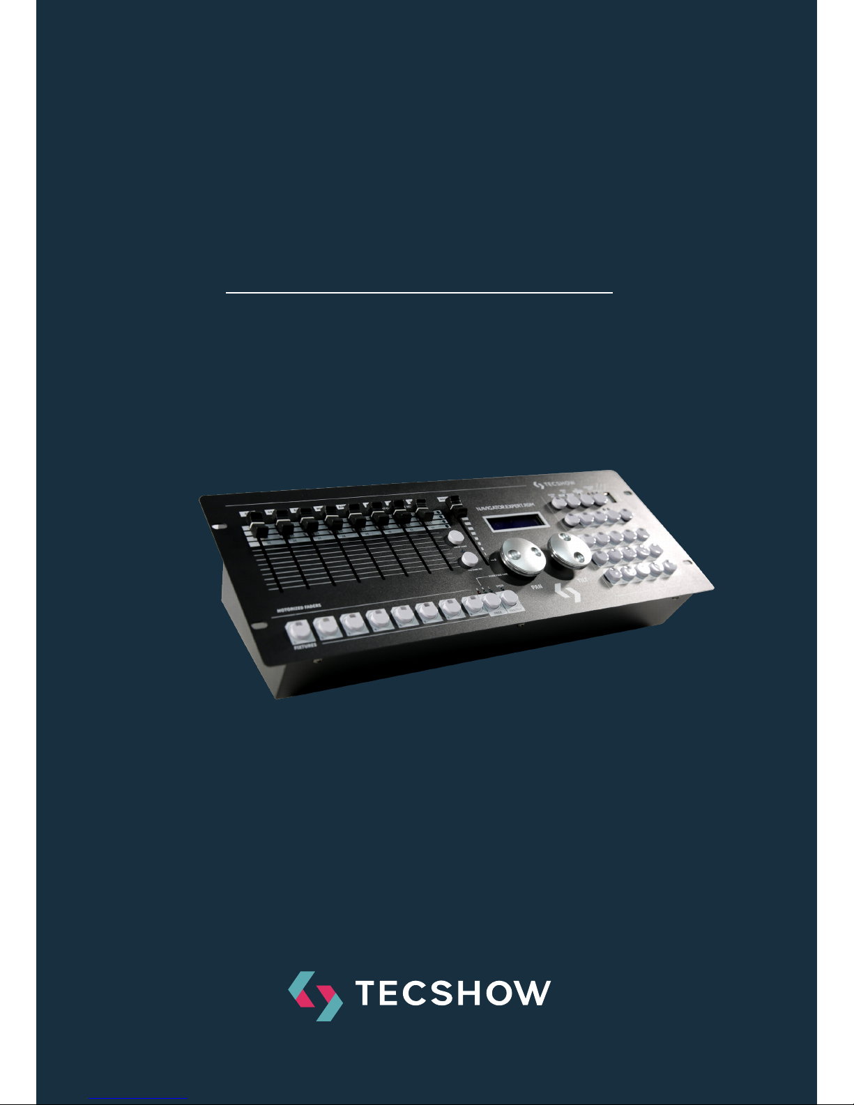
NAVIGATOR
SMART RDM
USER MANUAL / MANUAL DE USUARIO
PLEASE READ THE INSTRUCTIONS CAREFULLY BEFORE USE /
POR FAVOR LEA LAS INSTRUCCIÓNES ANTES DE USAR
Page 2

NAVIGATOR SMART RDM
P.
2
1. Overview
Navigator RDM Smart is a next-gen DMX controller able to
manage 24 units up to 26 channels each, with a total of 36
chases with 100 steps per chase and 36 scenes. As a huge
innovation for a compact controller, this board incorporates RDM function to remotely address your RDM-compatible units. Navigator.RDM.Smart also sports a USB port
for data backup and firmware update and let the user to
sopatch faders & control wheels easily. Last but not least,
the controller has a built-in eect generator with complex
eects & movement settings that can be run simultaneously.
Specifications
Interface
• 2 x 16-digit Backlit LCD display
• 8 faders for manual control - 3 pages
• 2 control wheels for Pan & Tilt
• 12 buttons to execute 8 integrated movements +
4 color eects
• Hue, Saturation & Value knobs
• Color-illuminated buttons
• Blackout button
• Fog-machine button
Features
• 512 DMX channels - Up to 24 units of 26 DMX ch.
• 36 programmable scenes
• 36 chases with 100 steps
• 12 built-in eect programs
• Built-in eect generator
• HSV color mixing
• Assignable fade time
• RDM support
• Sound control via built-in microphone
• Faders & control wheels are so patch
Connections
• 1 XLR-3 DMX Output connector
• 1 USB Port
• 1 Power Input
Physical
• Dimensions: 483x171x89 mm. / 19x6.7x3.5 in.
• Weight: 2.3 Kg. / 5 Lbs.
ENGLISH VERSION
Page 3
NAVIGATOR SMART RDM
P.
3
2. Introduction
• Keep this device away from rain and moisture
• Please read the user manual carefully before use.
• The device firmware can be updated.
• Please check if a new version is available online.
ENGLISH VERSION
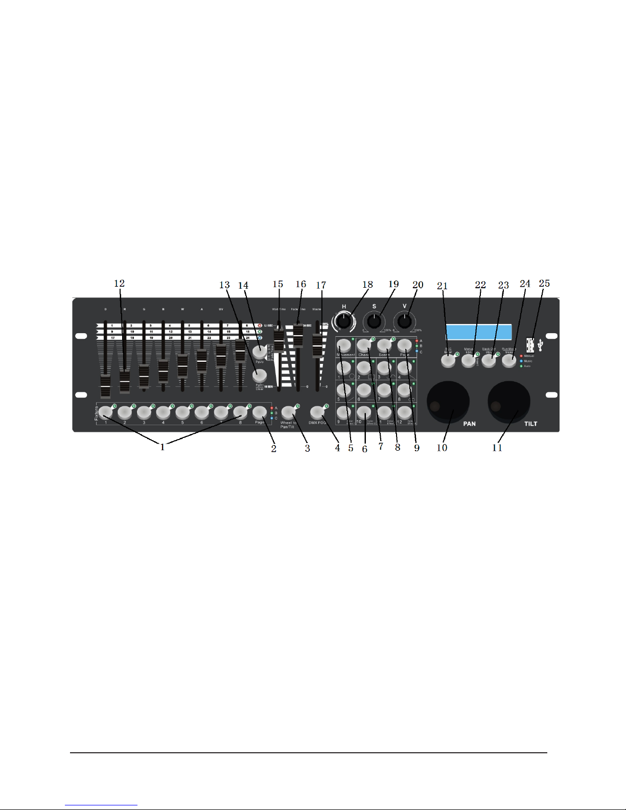
1. Fixture button: Units: 1-8 have 3 pages, total
control of 24 fixtures.
2. Fixture page button: Unit Pages
3. Wheel Button to PAN/TILT: Function select,
if the LED flicker, PAN/TILT wheel control PAN
/TILT channels, if the LED OFF, PAN/TILT is
other function.
4. DMX fog Button: DMX Fog machine control,
press once and the machine is ON, press
twice and is OFF.
5. “Movement” button: When activated, the
1-12 number buttons are for built in move
ments.
6. 1-12 Number button: Function diferently in
dierent modes.
7. Chase button: When activated, the 1-12
number buttons are for chases.
8. Scene button: When activated, the 1-12
number buttons are scenes.
9. Number button PAGE: In Chase and scene
mode, can use the button select diferently
page.
10. PAN Wheel Button: If “wheel to pan/tilt” LED
flicker, the PAN wheel control PAN channel,
if “wheel to pan/tilt” LED OFF, the PAN wheel
control other parameter,for example, in
MOVEMENT mode, PAN wheel can control
PAN channel move range.
Page 4
NAVIGATOR SMART RDM
P.
4
ENGLISH VERSION
Back Side
11. Tilt wheel: if “wheel to pan/tile” LED flicker, the
TILT wheel controll TILT channel, if “wheel to pan/
tilt” LED OFF, the TILT Wheel controll other pa-
rameter, for example , in “MOVEMENT” mode, TILT
wheel can control TILT move range.
12. Faders: Channels faders, have 3 page.
13. PAGE DOWN/CLEAR button: It has 2 func-
tions, press the button, select next page faders,
press and hold 3s, will clear faders change output.
14. PAGE UP/FADER TIME setup: The button have 2
functions, press the button select previous page
faders. Press and hold the button, then change
“wait timer” fader, will change color channel fade
in and fade out time.
15. Wait time fader: In chase mode, run chases, change
the fader will change chases setp to setp wait time.
16. Fade time fader: (Chase Mode) Run chases, change
the fader will change chases setp to setp fade time.
17. Master fader: Change the fader, will change
R,G,B,W,A,D maximum output ratio.
18. Hue knob: Control LED light color mixing.
19. Saturation knob: Control LED light color mixing
saturation.
20. Brightness knob: Control LED light color mixing
brightness.
21. REC/ENTER button: The button have 2 functions,
in program mode, is recode command, in menu
mode, is enter command.
22. Menus/ESC button, press and hold 3s, will activate
menu’s mode. In menu mode, press the button,
cancel or ESC setup.
23. Black out/DEL: In running mode, press the button,
will black-out. In program mode, press and hold
the button, Then press number button(1-12), can
DEL a chase or a scene.
24. Run mode/swap button: The button have 2 fun ctions, in running mode press the button and it can
change chase run mode. In “movement” mode can
swap movement parameter select.
25. USB host interface: Controller data buckup and
firmware update.
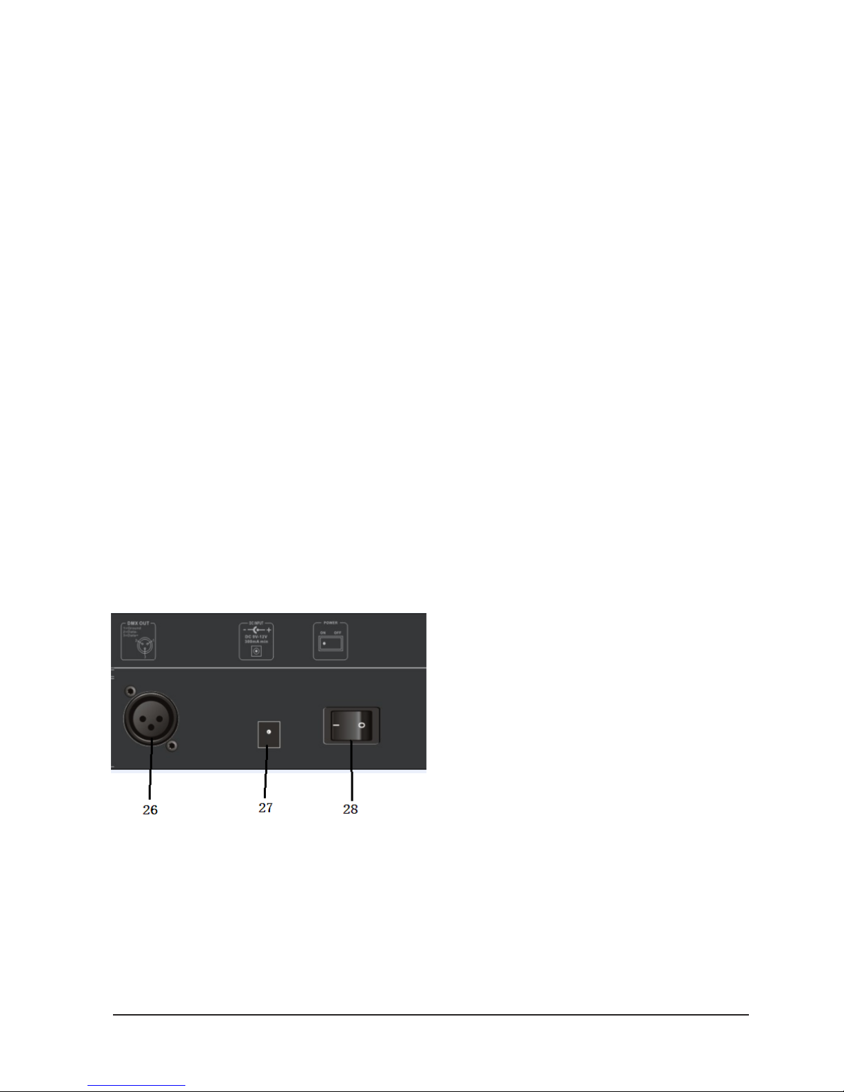
26. DMX OUT/INPUT
27. DC input
28. Power ON/OFF switch.
Page 5
NAVIGATOR SMART RDM
P.
5
ENGLISH VERSION
3. Number buttons
• In CHASE mode, press a number button and the
chase will be activated or inactivated.
• In SCENE mode, press a number button and the
scene will be activated or inactivated.
• In MOVEMENT mode, press a number button,
and the movement will be activated or inactivated.
4. Faders
• Move a fader to adjust the DMX output value.
• PAN/TILT wheels
• Pan/Tilt wheels function dierently in dierent
modes:
- In menus mode , PAN/TILT chose menus.
- In runing mode “wheel to pan/tilt”LED
flicker: If have FXITURE activated, PAN/
TILT wheels are to adjust the output val ues of PAN/TILT.
- In runing mode wheel to pan/tilt LED OFF:
- If have MOVEMENT activated, PAN/TILT
wheels are to adjust the MOVEMENT run ing parameters.
5. Patch fixtures and faders
• Before using your Show Design 3, you need to
patch the DMX start address of fixtures and the fad ers channel position.
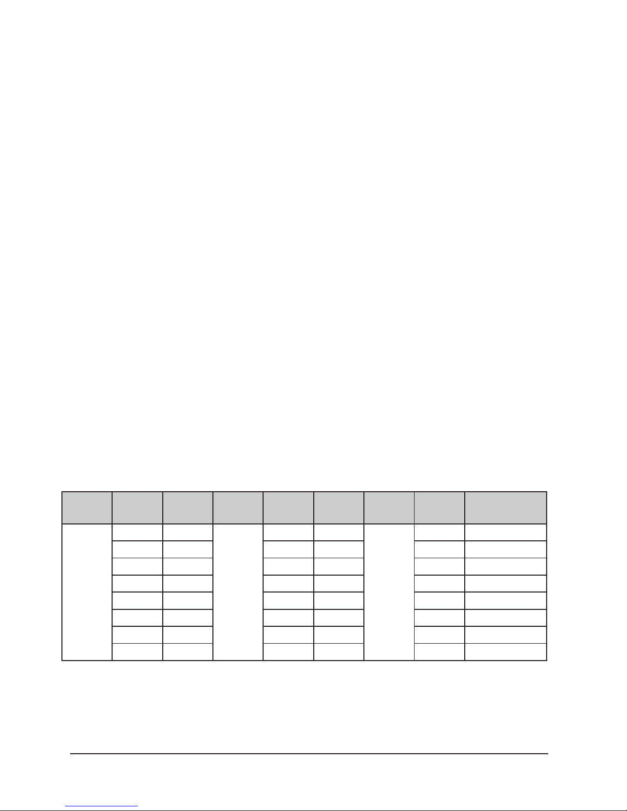
The default fixture patch setting is as below:
Page Fixture Start
Address
Page Fixture Start
Address
Page Fixture Start Address
A
1 1
B
9 209
C
17 417
2 27 10 235 18 443
3 53 11 261 19 469
4 79 12 287 20 495
5 105 13 313 21 6 131 14 339 22 7 157 15 365 23 8 183 16 391 24 -
Page 6
NAVIGATOR SMART RDM
P.
6
ENGLISH VERSION
Fader DMX Channel Fader DMX Channel Fader DMX Chan-
nel
1/D 1 10 10 19 19
2/R 2 11 11 20 20
3/(G 3 12 12 21 21
4/B 4 13 13 21 22
5/W 5 14 14 23 23
6 6 15 15 24 24
7 7 16 16 PAN 25
8 8 17 17 TILT 26
9 9 18 18
The default fixture channels patch setting is as below:
• In the above table, R: Red, G: Green, B: Blue,
W: White, D: Dimmer.
• FIXTURE starting address + FADER position DMX
Channel - 1: DMX address.
• For example: In default fixture patch setting,
FIXTURE 1 PAN DMX channel is 25, fxiture 2
PAN DMX address is 51.
• The DMX start address of fixtures and the faders
DMX channel position can be pacthing as needed.
• In Show Design 3 you need to patch the fixture’s
DMX start address. For example, if you are patch ing a moving head, you must patch the pan/tilt
channels of the moving head to PAN/TILT wheels
on Show Design 3; If you are patching an LED fix ture, then, you must patch the Red, Green, Blue,
White and Dimmer channels to the corresponding
faders respectively. Show Design 3 will then be
able to run the built-in movements and fade in/out
eects with the patch setting.
Page 7

NAVIGATOR SMART RDM
P.
7
ENGLISH VERSION
6. Menu Options
Patch fixture
1. Rotate the PAN wheel to locate 01. Patch fixture.
2. Press ENTER to confirm.
3. Select a fixture (only one fixture can be selected).
Press SWAP to switch between the four settings:
- Dmx Start Address
- Fader Channel
- Fader Reverse
- Color Fade.
4. In DMX START ADDRESS, rotate the PAN wheel to
adjust the DMX start address; press ENTER to
save or press ESC existing pach mode, DEL to de lete the existing DMX start address.
5. In “FADER CHANNEL”, rotate the PAN wheel to se lect a fader name within 1/D to TILT. Rotate the
TILT wheel to adjust the address of the corres-
ponding DMX channel within 1-40. Press ENTER
to save the patching or press DEL to delete the ex isting patching.
6. In “FADER REVERSE”, rotate the PAN wheel to se lect a fader name within 1/D to TILT. Rotate the
TILT wheel to select YES or NO; YES means to set
the corresponding channel reverse; NO means in verse. Press ENTER to save the setting.
7. In COLOR FADE, you can enable or disable the
fade in/out time of the fixture’s color channels.
Rotate the PAN wheel, select YES or NO; YES
means to enable; NO means to disable. Press EN-
TER to save the settings.
8. To copy a patched fixture to a new fixture, press
and hold the fixtre button of the patched fixture,
then, press the fixtrue button of a new fixture.
9. Press ESC to exit patch setting.
10. The settings of DMX START ADDRESS + FADER
CHANL - 1= FADER DMX ADDRESS.
- For example, FIXTURE 1 is set to 11 as
its DMX start address and its 1/D fad er channel is set to 1. Then, move the 1st
fader (1/D of FIXTURE 1), the output of
the 11th DMX channel will be changed.
But, if FIXTURE 1 is set to 11 as its DMX
start address and its 1/D fader channel is
set to 10, then, move the 1st fader (1/R
of FIXTURE 1), the output of the 20th
DMX channel will be changed.”
11. When in patching, a “!” mark is shown in
the LCD display means there is a overlap
in the patching of DMX channels. This shall be
corrected; Otherwise, the DMX may run in error.
- For example: FIXTURE 1 start DMX ad-
dress is 001, if the fixture have 26 chan nels mode. So other fixture can not
patch 001-026, other start DMX address
must be then 026. if other fixture start
DMX channel less-than 026, FIXTURE 1
channel will overlap, LCD will display “!”
ma r k. If FIXTURE 1 only 10 channels user,
you can delete 11-26 fader patch,
then other fixture DMX start address can
patch in 011.
Page 8

NAVIGATOR SMART RDM
P.
8
ENGLISH VERSION
7. Reset factory
(to restore the factory settings)
1. Rotate the PAN wheel to locate 02. Reset factory.
2. Press ENTER to confirm.
3. Rotate the PAN wheel to select YES or NO.
4. Press ENTER to confirm or press ESC to return to
the main menu.
8. Delete all Fixture patch
1. Rotate the PAN wheel to locate 03. and then
delete all Fixture patch”.
2. Press ENTER to confirm.
3. Rotate the PAN wheel to select YES or NO.
4. Press ENTER to confirm or press ESC to return to
the main menu.
9. Fade mode
Setup controller fade mode.
• ALL CHANNEL: run chases, all channels will fade
in and fade out.
• ONLY PAN/TILT: run chase, onlay PAN/TILT have
fade in and fade out.
1. Rotate the PAN wheel to locate “04.
Fade mode”
2. Press ENTER to confirm.
3. Rotate the PAN wheel to select ALL
CHANNEL or ONLY PAN/TILT.
4. Press ENTER to confirm or press ESC to
return to the main menu.
10. RDM DMX Address setup
• Rotate the PAN wheel to locate “05. RDM DMX Ad-
dress setup”.
• Press ENTER to confirm.
• Rotate the PAN wheel to select YES or NO; If YES
you will enter RDM operation.
• Show Design 2 will start searching RDM devices
and will show the number of RDM devices.
• Rotate the PAN wheel to select an RDM device; ro-
tate the TILT wheel to adjust the DMX address of
the RDM device. Press ENTER to confirm.
• Press SWAP to switch the information of the se-
lected device; Press DEL to verify selected dvice.
• Press ESC to return to the main menu.
11. Data backup
• Rotate the PAN wheel to locate 06. Data backup.
• Press ENTER to confirm.
• Rotate the PAN wheel to select YES or NO; press
ENTER to confirm.
• Press a number button(1-12) to store the back-up
file. 12 files can be backed up in Show Design 3,
respectively stored in Number 1-12 buttons. If the
LED indicator of a number button is on, it means
there is back-up file in this position.
• Press ESC to return to the main menu.
12. Data Load
• Rotate the PAN wheel to locate “07. data load”,
• Press ENTER to confirm.
• Rotate the PAN wheel to select YES or NO; Press
ENTER to confirm.
• Press a number button (1-12) to load the back-
up file. 12 files can be backed up in Show Design
3, respectively stored in Number 1-12 buttons. If
the LED indicator of a number button is on, it
means there is back-up file in this position.
13. Send fixture Update file
• Through the DMX cable, send fixture firmwarcode.
• Insert a USB memory stick to the USB port.
• Rotate the PAN wheel to locate “08. Send fixture
Update file”.
• Press ENTER to confirm.
• Rotate the PAN wheel to locate the file to send.
• Press ENTER to start sending.
• Repeat Step 5 to send another file.
• Press ESC to exit.
Page 9

NAVIGATOR SMART RDM
P.
9
ENGLISH VERSION
14. Black-out mode
• Setup black-out mode.
• Rotate the PAN wheel to locate “09.Black-out
mode”
• Press ENTER to confirm.
• Rotate the PAN wheel to select “only dimmer” or
“all channels”.
• Press ENTER to save setup or press ESC to return
to the main menu.
- Only dimmer: press “Black-out” button
only dimmer channels black-out(DMX
output 0 value.)
- All channels: press “Black-out” button
all channels black-out(DMX out 0 vlaue)
15. Fog machine control”
The menus setup fog machine DMX channel/DMX output
value/on-o time
1. Rotate the PAN wheel to locate “10 fog control.
2. Press ENTER to confirm.
3. Press SWAP to switch between the four
settings: Auto FOG/ON TIME OFF TIMER/
FOG CH 1/FOG CH2.
- In “Auto FOG” ON/OFF fog time control.
- In “ON TIME/OFF TIMER” setup fog ma-
chine ON/OFF time.
- In “FOG CH1/ VALUE” setup fog machine
channel 1 DMX address and DMX value.
- In “FOG CH2/ VALUE” setup fog machine
channel 2 DMX address and DMX value.
- If “Auto FOG” setup “ON”, will according
setup time ON/OFF fog machine.
Page 10

NAVIGATOR SMART RDM
P.
10
ENGLISH VERSION
16. Control Fixtures by Manual
1. Select the desired fixtures with the number but tons (1-8) and the PAGE button (PAGE A: 1-8,
PAGE B:9-16, PAGE C:17-24).
2. Move the faders and/or PAN/TILT wheels to ad
just the DMX output values.
3. In Step 2, fixtures can be selected one by one; Alternatively, you can select more fixtures in a single operation. For example, to select Fixture 1-8, you can press and
hold the number button 1 and then press the number
button 8, Fixture 1-8 will all be selected. The same can be
applied to deselect fixtures.
17. H/S/V control
1. HSV control, all fixtures must be patched correct
ly. (Refer to “01. Patch fixture”.)
2. This function is mainly to control led lights.
3. H knob: Hue, rotate the knob, will control led
light RED/GREEN/BLUE color mixing
4. S knob: Saturation, mixed color saturation.
5. Vknob: Brightness, mixed color brightness.
18. Movement
There are 12 built-in movements in Show Design 3. 8 of
them are for moving heads and the rest 4 are for LED fixtures. Before running a movement, all fixtures must be
patched correctly. (Refer to “01. Patch fixture”.)
1. Select the desired fixtures with the number but tons (1-18) and the PAGE button (PAGE A: 1-8,
PAGE B:9-16, PAGE C:17-24)
2. Press MOVEMENT to activate the mode.
3. Select a desired MOVEMENT with the number
buttons (1-12). Movement 1-8 is for the pan/
tilt movement of moving heads. “MOVEMENT
RANGE” is 0-100% adjustable; “MOVEMENT OFF
SET” is 0-255 adjustable; “MOVEMENT SPEED”
is to adjust the movement speed and “DELAY LEV-
EL” is to adjust the delay level from fixture to
fixture, the more fixtures you have the greater
level you need. Press SWAP to switch between the
adjustable parameters.
Movement 9-12, non-adjustable, is for R/G/B ef fects of LED fixtures.
19. Editing
Press and hold REC for 2 seconds to activate or inactivate
Editing mode.
Scene Editing
Channels and movements can be edited in a scene
Activate Editing mode.
1. Select the desired fixtures with the number but tons (1-18) and the PAGE button(PAGE A: 1-8,
PAGE B:9-16, PAGE C:17-24) .
2. Move the faders and/or wheels to adjust the DMX
output values. Movements can also be included.
3. Press REC to get ready to save.
4. Press SCENE and then press a number button to
save the scene. There are three pages (Page A and
B,C) to save the scenes. Once a scene is saved
successfully,allLED indicators will blink3 times.
5. Repeat Step 2-5 to edit another scene.
Chase Editing
Channels, scenes and movements can be edited in a
chase.
1. Activate Editing mode.
2. Press CHASE (indicator on).
3. Select a number button for the chase.
4. Move the faders and/or wheels to adjust the DMX
output values. Scenes and/or movements can
also be included.
5. Press REC to save the current step.
6. Repeat Step 4-5 to edit a new step. You can rotate
Page 11

NAVIGATOR SMART RDM
P.
11
ENGLISH VERSION
the PAN wheel to browse all the steps. You can
also press INSERT to insert a step.
7. When all the steps are edited, press the number
button to save and exit (step 3 same button).
Run Scenes
1. Pess SCENE (indicator on).
2. Press the number button(s) to activate the
scene(s).
Run Chases
1. Press and hold “PgDn/Clear” 3s, clear manual
move fader output.
2. Press CHASE (indicator on)
3. Press the number button(s) to activate the
chase(s). Maximum 5 chases can be output simul taneously.
4. Press RUN MODE to select a run mode:
- AUTO: Chases run in the sequences of
the numbers.
- MANUAL: Rotate the PAN wheel to run
step by step, forward or backward.
- MUSIC: The chases will be activated by
sound. To adjust the sensitivity of sound
activation in MUSIC mode, press and
hold and then rotate the TILT wheel.
When two or more chases are running si multaneously, the chase that is adjust able shows a blinking LED indicator. To
adjust another chases, press the corre sponding number button for 2 seconds
till its LED indicator blinks, then, it is
ready for adjustment. The last activated
chase will always be adjustable.
Move “wait timer” fader can to adjust
chase wait time; move “fade time” fader
to adjust chase fade time.
Controller runing output priority is: manual move fader >
movement>scene>chase,
Means is if mnaual move fader, change dmx output, will
override movement/ scene/ chase output.
- For example: activated ctivation FIX-
TURE 1(LED ON manual move fader 2 (R
fade), change the channel output(out
put not vlaue 0), Will override move
ment/ scene/ chase output same chan
nel output. So if a chase in runing, use
have manual control fixture fader out
put, chase same channels will no out
put, because mnaual move fader output
priority is than chase output.
Fade In/Out Time of the Color Ch.
Press “PgUp” button and hold then move “wait time” to
adjust the fade in/out time of the color channels. Each fixtre can be set individually fade in/ fade out, Fade in/out
time can be set enabled/disabled (refer to “01. Patch fixture”.)
Firmware Update
• Create a folder named “show-design3” in the
root directory of your USB memory stick.
• Copy the update file “show_design3.upd”.
• Insert the USB memory to the USB port.
• Power o Show Design 3.
• Press and hold REC + BLACK OUT + RUN MODE.
• Power on Show Design 3 and wait for about 3 sec
till the LCD display shows “PRESS ANY BUTTON TO
UPDATE”
• Release REC + BLACK OUT + RUN MODE.
• Press any button, then, it will start updating.
• Once the update is completed, power o Show
Design 3 and power on again; Then, the updated
firmware is now in service.
Page 12

NAVIGATOR SMART RDM
P.
12
VERSION ESPAÑOL
1. Descripción
Navigator.RDM.Smart es una consola DMX next-gen que
controla 24 unidades de hasta 26 canales cada una, con un
total de 36 chases con 100 pasos y 36 escenas. Como una
de sus mayores innovaciones, este controlador incorpora
la función RDM para direccionar remotamente los equipos
RDM-compatibles. Navigator.RDM.Smart también posee
un puerto USB para realizar backups y actualizar su firmware, y cuenta con sopatch tanto para faders como para
las ruedas de control. Por último, el controlador detenta
un generador de efectos incorporado que permite ejecutar
simultáneamente complejos efectos y movimientos preestablecidos
Especificaciones
Interface
• Display LCD con 2 filas de 16 digitos
• 8 faders para control manual - 3 páginas
• 2 Ruedas de control para Pan & Tilt
• 12 botones para ejecutar 8 movimientos
integrados + 4 efectos de color
• Encoders de matiz, saturación y valor
• Botones iluminados
• Botón directo para maquina de humo
• Botón directo para Black Out
• Características
• 512 canales DMX – Hasta 24 dispositivos de 26
canales DMX
• 36 escenas programables
• 36 chases con 100 pasos
• 12 programas integrados
• Generador de efectos integrado
• Mezcla de color HSV
• Tiempo de fade asignable
• Soporte RDM
• Control de sonido via micrófono incorporado
• Faders y encoders so patch
• Conexiones
• 1 conector XLR de 3 pines: DMX de Salida
• 1 puerto USB
• 1 entrada de alimentación
Físico
• Dimensiones: 483x171x89 mm. / 19x6.7x3.5 in.
• Peso: 2.3 Kg. / 5 Lbs.
Page 13

NAVIGATOR SMART RDM
P.
13
VERSION ESPAÑOL
2. Introducción
• Mantener el Equipo fuera del Agua.
• Por favor leer bien el manual previamente.
• El firmware puede ser actualizado.
• Chequear nuevas versiones disponibles.
1. Tecla Fixture: Unidades 1-8 en 3 páginas.
Control total de 24 unidades.
2. Tecla Page: Páginas de unidades.
3. Tecla Wheel to PAN/TILT: Con el LED titilante,
la perilla de control regula los canales de pan/
tilt. Con el LED apagado, regula otros
parámetros.
4. Tecla DMX fog: Control DMX de la máquina de
humo. Presione una vez para encender la
máquina de humo. Presione nuevamente para
apagarla.
5. Tecla Movement: Al activarla, las teclas 1-12
ejecutan los movimientos integrados.
6. Teclas 1-12: Cuentan con diversas funciones
según el modo seleccionado.
7. Tecla Chase: Al activarla, las teclas 1-12 se
emplean para los chases.
8. Tecla Scene: Al activarla, las teclas 1-12 se
emplean para las escenas.
9. Tecla Page: Seleccione el número de página
en los modos Chase y Scene.
10. Perilla de PAN: Con el LED titilante de Wheel
to PAN/TILT, la perilla de PAN regula el canal
pan. Si el LED está apagado, la perilla de
PAN regula otros parámetros. Por ejemplo,
el modo movimiento (tecla movement).
La perilla de PAN también regula el rango
de movimiento del pan.
11. Perilla de TILT: Con el LED titilante de Wheel
Page 14

NAVIGATOR SMART RDM
P.
14
VERSION ESPAÑOL
Back Side
to PAN/TILT, la perilla de TILT regula el canal tilt.
Si el LED está apagado, la perilla de TILT regula
otros parámetros. Por ejemplo, el modo mov imiento (tecla movement). La perilla de TILT tam
bién regula el rango de movimiento del tilt.
12. Faders: Los canales de faders cuentan con 3 pág.
13. Tecla Page Down/Clear Page down: presione la
tecla una vez para seleccionar la página siguiente.
Clear: presione la tecla durante tres segundos
para borrar el valor de salida de los faders.
14. Tecla Page Up/Fader Time Page Up: Presione
la tecla una vez para seleccionar la página previa.
Fader Time: Presione la tecla durante tres se gundos, luego modifique el fader “wait time”
(tiempo de espera). Modificará el tiempo de fade
in/out del canal de color.
15. Fader Wait Time: En modo chase, esta tecla eje cuta chases. Modificar el fader hará que cambie
el tiempo de espera de los chases.
16. Fader Fade Time: En modo chase, esta tecla eje cuta chases. Modificar el fader hará que cambie
el tiempo de fade de los chases.
17. Fader Master : Modificar el fader hará que cambie
el radio máximo de salida de R, G, B, W, A, D.
18. Perilla Hue: Regula la mezcla de color de las lu ces LED.
19. Perilla Saturation: Regula la saturación de la
mezcla de color de las luces LED.
20. Perilla Brightness: Regula el brillo de la mezcla
de color de las luces LED.
21. Tecla REC/ENTER Rec: En modo program, esta
tecla realiza grabaciones. Enter: en modo menus,
ingresa comandos.
22. Tecla Menus/ESC: Presione la tecla durante tres
segundos para activar el modo menus. Dentro
del modo menus, presione la tecla para cancelar
o salir de la configuración.
23. Tecla Black out/DEL Black out: En modo run, la
tecla entrará en modo blackout. DEL: en modo
program, mantenga presionada la tecla y luego
presione una tecla numérica (1-12) para eliminar
un chase o una escena.
24. Tecla Run mode/swap Run mode: En modo run,
podrá cambiar el modo de ejecución de un chase
(manual, auto, music). Swap: en modo move ment, podrá intercambiar la selección de
parámetros de movimiento.
25. Interfaz USB: Para hacer una copia de seguridad
del controlador y para actualizar el firmware.
26. Entrada y Salida DMX
27. Entrada CC
28. Interruptor de encendido/apagado.
Page 15

NAVIGATOR SMART RDM
P.
15
VERSION ESPAÑOL
3. Teclas 1-12
• En modo CHASE, presione una tecla numérica para
activar o desactivar un chase.
• En modo SCENE, presione una tecla numérica para
activar o desactivar una escena.
• En modo MOVEMENT, presione una tecla numérica
para activar o desactivar el movimiento.
4. Faders
• Deslice un fader para regular el valor de salida DMX
• Las perillas desempeñan funciones diferentes de
acuerdo con el modo seleccionado.
- En modo Menu, la perilla selecciona menú:
- En modo running, si el indicador LED de
Wheel to pan/tilt titila: La función FIXTURE
está activa, las perillas de pan/tilt regulan
los valores de salida del pan y el tilt.
- En modo running, si el indicador LED de
Wheel to pan/tilt está apagado: La función
MOVEMENT está activa, las perillas de
pan/tilt regulan los parámetros de mov.
5. Patch de unidades y faders
• Antes de utilizar su Navigator Smart RDM, el usu-
ario debe realizar un patch de la dirección de inicio de las
unidades y de la posición de los canales de los faders
La configuración por defecto es la siguiente:
Página Unidad DMX
Inicio
Página Unidad DMX
Inicio
Página Unidad DMX Inicio
A
1 1
B
9 209
C
17 417
2 27 10 235 18 443
3 53 11 261 19 469
4 79 12 287 20 495
5 105 13 313 21 6 131 14 339 22 7 157 15 365 23 8 183 16 391 24 -
Page 16

NAVIGATOR SMART RDM
P.
16
VERSION ESPAÑOL
Fader Canal DMX Fader Canal DMX Fader Canal DMX
1/D 1 10 10 19 19
2/R 2 11 11 20 20
3/(G 3 12 12 21 21
4/B 4 13 13 21 22
5/W 5 14 14 23 23
6 6 15 15 24 24
7 7 16 16 PAN 25
8 8 17 17 TILT 26
9 9 18 18
La configuración por defecto del patch de los canales es la siguiente:
• En el Cuadro: R: Rojo, G: Verde, B: Azul,
W: Azul, D: Dimmer.
• FIXTURE starting address + FADER position DMX
Channel - 1: DMX address.
• Por Ejemplo: Canal DMX del PAN de la unidad 1 =
25. Dirección DMX del PAN de la unidad 2 = 51.
• El usuario puede asignar todos los patches que
necesite a la dirección DMX de inicio de las uni dades y a la posición del fader en el canal DMX.
• Con el Navigator Smart RDM, tendrá que realizar
un patch de la dirección DMX de inicio de la un idad. Por ejemplo, si hará un patch de un cabezal
móvil, tendrá que hacer un patch de los canales de
pan/tilt del cabezal y de las perillas de pan/tilt en
el controlador.
• Si hará un patch de una unidad LED, tendrá que
hacer un patch de los canales rojo, verde, azul,
blanco y dimmer en los faders correspondientes.
Una vez realizados los patch, el Navigator Smart
RDM podrá ejecutar los movimientos incorpora dos y los fade in/out de efectos con los nuevos
parámetros.
•
6. Funciones del menú
Menú Enter/Exit
1. Presione la tecla MENUS durante tres segun dos para ingresar al/salir del modo Menu. Visu
alizará las siguientes opciones:
2. Patch fixture: Realizar patches de las direcciones
de inicio de las unidades y las posiciones.
3. Reset factory: Restablecer los valores de fábrica.
4. Delete all Fixture patch: Borrar las configura-
ciones de patches.
5. Fade mode: Configurar el modo de fade: “ALL
CHANNEL” u “ONLY PAN/TILT”.
6. RDM DMX Address setup: Utilizar funciones RDM.
7. Data back up: Realizar una copia de seguridad en
una memoria portátil USB.
8. Data load: Cargar datos desde una memoria
portátil USB.
9. Send fixture Update file: Enviar el código de ac tualización de la unidad.
10. Black-out mode: Configurar el modo black out.
Page 17

NAVIGATOR SMART RDM
P.
17
VERSION ESPAÑOL
11. Fog machine control: Configurar el control de la
máquina de humo.
12. Utilice la perilla de PAN para desplazarse entre las
opciones del menú.
Opciones del menú
Patch fixture
1. Gire la perilla de PAN hasta visualizar “01. Patch
fixture”.
2. Presione ENTER para acceder.
3. Seleccione una unidad.
4. Presione la tecla SWAP para desplazarse entre
los parámetros: DMX START ADDRESS, FADER
CHANL, FADER REVERSE y COLOR FADE.
5. En “DMX START ADDRESS”, gire la perilla de PAN
para regular la dirección DMX de inicio. Luego
presione ENTER para guardar los cambios, ESC
para salir o DEL para eliminar la dirección actual.
6. En “FADER CHANL”, gire la perilla de PAN para se-
leccionar un nombre de fader desde “1/D” a
“TILT”. Gire la perilla de TILT para regular la direc-
ción del canal DMX correspondiente de 1-40. Lue go presione ENTER para guardar los cambios o
DEL para eliminar el patch actual.
7. En “FADER REVERSE”, gire la perilla de PAN para
seleccionar un nombre de fader desde “1/D” a
“TILT”. Gire la perilla de TILT para seleccionar en-
tre YES (revertir el canal correspondiente) o NO
Luego presione ENTER para guardar los cambios.
8. En “COLOR FADE”, el usuario podrá habilitar o
deshabilitar el tiempo de fade in/out de los cana les de color de la unidad. Gire la perilla de PAN
para seleccionar YES (habilitar) o NO. Luego pre-
sione ENTER para guardar los cambios.
9. Para copiar el patch de una unidad a otra, man tenga presionada la tecla Fixture numérica que
corresponde a la unidad con el patch ya asignado
y luego presione la tecla Fixture de la nueva uni dad en la cual desea copiar el patch.
10. Presione ESC para abandonar el menú de patch.
11. La configuración “DMX START ADDRESS” + “FAD
ER CHANL” - 1= DIRECCIÓN DMX DEL FADER.
- Por ejemplo: La unidad 1 tiene una di rección DMX de inicio 11 y su canal de
fader 1/D es 1. Luego, deslice el primer
fader (1/D de la unidad 1), la salida de
canal DMX 11 se modificará. Pero si la
unidad 1 tiene dirección DMX de inicio
11 y su canal de fader 1/d es 10, deberá
deslizar el primer fader.
- Si en el menú de patch, visualiza el sím bolo “!” en la pantalla, existe una su perposición en la asignación de patches
de canales DMX. Proceda a corregir el er ror o la salida DMX funcionará con error.
- Por ejemplo: Si la unidad 1 tiene modo
de 26 canales y una dirección de inicio
001, otras unidades no pueden contar
con patches en los canales 001-026. Si
otra unidad cuenta con una dirección de
inicio menor a 026, habrá una super
posición de canales y verá el símbolo “!”
en la pantalla. En caso de que la unidad
1 cuenta con 10 canales, es posible elim inar los patches de fader del 11-26 para
que una segunda unidad pueda contar
con dirección de inicio 011.
Page 18

NAVIGATOR SMART RDM
P.
18
VERSION ESPAÑOL
7. Restablecer de Fábrica
(Para restablecer todo)
1. Gire la perilla de PAN hasta visualizar “02. Reset
factory”.
2. Presione ENTER para acceder.
3. Gire la perilla de PAN para seleccionar entre YES
y NO.
4. Luego presione ENTER para confirmar o ESC
para regresar al menú principal.
8. Borrar Fixture Patch
1. Gire la perilla de PAN hasta visualizar “03. Delete
all Fixture patch”.
2. Presione ENTER para acceder.
3. Gire la perilla de PAN para seleccionar entre YES
y NO.
4. Luego presione ENTER para confirmar o ESC
para regresar al menú principal.
9. Modo Fade
Configuración del controlador
• ALL CHANNEL: Ejecuta chases, habrá fade in/out
en todos los canales
• ONLY PAN/TILT: Ejecuta chases, habrá fade in/
out solo en PAN/TILT..
1. Gire la perilla de PAN hasta visualizar “04. Fade
mode”.
2. Presione ENTER para acceder.
3. Gire la perilla de PAN para seleccionar entre ALL
CHANNEL y ONLY PAN/TILT.
4. Luego presione ENTER para confirmar o ESC
para regresar al menú principal.
10. RDM DMX Address setup
• Gire la perilla de PAN hasta visualizar “05. RDM
DMX Address setup”.
• Presione ENTER para acceder.
• Gire la perilla de PAN para seleccionar entre YES
y NO. Presione YES para seleccionar la utilización
de funciones RDM y luego ENTER para confirmar.
• Navigator Smart RDM comenzará a buscar servici-
os RDM y mostrará el número de dispositivos RDM.
• Gire la perilla de PAN para seleccionar el dispos-
itivo RDM. Gire la perilla de TILT para regular la di rección DMX de inicio de dicho dispositivo. Pre sione ENTER para confirmar.
• Presione la tecla SWAP para cambiar la infor-
mación del dispositivo seleccionado. Presione
DEL para verificar dicho dispositivo.
• Presione ESC para regresar al menú principal.
11. Back Up de Información
1. Gire la perilla de PAN hasta visualizar Data backup
2. Presione ENTER para acceder.
3. Gire la perilla de PAN para seleccionar entre YES y
NO. Luego presione ENTER para confirmar.
4. Presione una tecla numérica (1-12) para almace nar el archivo de copia de seguridad. Navigator
Smart RDM puede almacenar hasta 12 archivos. Si
el indicador LED de una tecla numérica está en cendido, esa tecla ya tiene un archivo guardado.
5. Presione ESC para regresar al menú principal.
12. Data Load
• Gire la perilla de PAN hasta visualizar Data load.
• Presione ENTER para acceder.
• Gire la perilla de PAN para seleccionar entre YES y
NO. Luego presione ENTER para confirmar.
• Presione una tecla numérica (1-12) para cargar
un archivo de copia de seguridad. Navigator Smart
RDM puede almacenar hasta 12 archivos.
•
13. Send fixture Update file
• Navigator Smart RDM puede enviar el código de
firmware vía cable DMX.
• Coloque una memoria USB en el puerto.
• Gire la perilla de PAN hasta visualizar Send fixture
Update file. Presione ENTER para acceder. Gire la
perilla de PAN hasta ubicar el archivo.
• Presione ENTER para comenzar el envío.
• Reitere los pasos 4 y 5 si desea enviar otro archivo.
• Presione ESC para abandonar el menú.
Page 19

NAVIGATOR SMART RDM
P.
19
VERSION ESPAÑOL
14. Black-out mode
Configuración del modo black out.
- ONLY DIMMER: El modo black out afec-
tará solo a los canales dimmer (valor de
salida DMX 0)
- ALL CHANNELS: El modo black out afec-
tará todos los canales.
1. Gire la perilla de PAN hasta visualizar Black-out mode.
2. Presione ENTER para acceder.
3. Gire la perilla de PAN para seleccionar entre “only dim-
mer” y “all channels”.
4. Luego presione ENTER para confirmar o ESC para regresar al menú principal.
15. Fog machine control”
Configuración de la máquina de humo, el valor de salida
DMX, tiempo de encendido/apagado.
1. Gire la perilla de PAN hasta ver fog machine.
2. Presione ENTER para acceder.
3. Presione la tecla SWAP para alternar entre los
cuatros parámetros: Auto FOG, ON TIME/OFF TIM
ER, FOG CH1/VALUE y FOG CH2/VALUE.
- Seleccione “Auto FOG” para controlar el
encendido y apagado.
- Seleccione “ON TIME/OFF TIMER” para
configurar el temporizador.
- Seleccione “FOG CH1/ VALUE” para con figurar la dirección y valor DMX del canal1.
- Seleccione “FOG CH2/ VALUE” para con-
figurar la dirección y valor DMX del canal2
Page 20

NAVIGATOR SMART RDM
P.
20
VERSION ESPAÑOL
16. Control manual de unidades
1. Seleccione la unidad deseada con la tecla Fixture
numérica (1-8) y la tecla Page correspondientes
(PAGE A: 1-8, PAGE B: 9-16, PAGE C: 17-24).
2. Deslice los faders o gire las perillas de PAN/TILT
para regular los valores de salida DMX.
3. En este paso, es posible seleccionar las unidades
de a una o seleccionar varias a la vez. Por ejemplo, para
seleccionar las unidades 1-8, mantenga presionada la te-
cla numérica 1 y luego la 8. Este mismo paso puede uti-
lizarse para cancelar la selección de las unidades.
17. Control de HSV
1. El control HSV se utiliza principalmente para las
luces LED y requiere que todas las unidades ten-
gan los patches asignados correctamente.
2. Perilla H: Hue (matiz). Regula la mezcla de color
RGB de las luces LED.
3. Perilla S: Saturation (saturación). Regula la satu-
ración de la mezcla de color.
4. Perilla V: Value (valor) o Brightness (brillo). Regu la el brillo de la mezcla de color.
18. Movimiento
Navigator Smart RDM cuenta con 12 movimientos incorporados, de los cuales 8 se utilizan con cabezales móviles
y los 4 restantes con unidades LED. Antes de ejecutar un
movimiento, todas las unidades deben tener sus patches
asignados correctamente (ver 01. Patch fixture).
1. Seleccione la unidad deseada con la tecla Fixture
numérica (1-8) y la tecla Page correspondientes
(PAGE A: 1-8, PAGE B: 9-16, PAGE C: 17-24).
2. Presione la tecla MOVEMENT para activar el
modo movement.
3. Seleccione el movimiento deseado con las teclas
numéricas (1-12). Los movimientos 1-8 están designados
al pan/tilt de cabezales móviles. La opción “MOVEMENT
RANGE” (rango de movimiento) se regula de 0-100%.
“MOVEMENT OFFSET” (compensación de movimiento) se
regula de 0-255. “MOVEMENT SPEED” se refiere a la velocidad del movimiento y “DELAY LEVEL” al retardo entre
unidad y unidad. A mayor número de unidades, mayor
el nivel de retardo requerido. Utilice la tecla SWAP para
desplazarse entre los parámetros. Los movimientos 9-12
no admiten modificaciones. Están designados para los
efectos RGB de las unidades LED.
19. Editando
Presione la tecla REC durante dos segundos para activar
y desactivar el modo Editing.
Editar Escena
El usuario puede editar los canales y movimientos de una
escena
1. Active el modo Editing.
2. Seleccione la unidad deseada con la tecla Fixture
numérica (1-8) y la tecla Page correspondientes
(PAGE A: 1-8, PAGE B: 9-16, PAGE C: 17-24).
3. Deslice los faders y/o gire las perillas de PAN/TILT
para regular los valores de salida DMX.
Presione la tecla REC para guardar los cambios.
4. Presione la tecla SCENE y luego una tecla
numérica para guardar la escena. Navigator Smart RDM
cuenta con tres páginas (page A, B y C) para almacenar
escenas. Una vez almacenada la escena correctamente, el
indicador LED titilará tres veces.
5. Reitere los pasos 2-5 si desea editar otra escena.
Editar Chase
El usuario también puede editar los canales, escenas y
movimientos de un chase.
1. Active el modo Editing.
2. Presione la tecla CHASE (indicar led encendido).
Page 21

NAVIGATOR SMART RDM
P.
21
VERSION ESPAÑOL
3. Seleccione una tecla numérica para el chase.
4. Deslice los faders y/o gire las perillas de PAN/
TILT para regular los valores DMX de salida, los
movimientos y/o escenas.
5. Presione la tecla REC para guardar.
6. Reitere los pasos 4-5 si desea editar un paso nue vo. Gire la perilla de PAN para desplazarse por los
diferentes pasos. O presione INSERT para agregar
un paso. Una vez editados todos los pasos, pre sione la tecla numérica correspondiente para
guardar los cambios y salir.
Ejecutar Escenas
1. Presione la tecla SCENE.
2. Presione la tecla numérica para activar la escena.
Ejecutar Chases
1. Presione la tecla “Page Down/Clear” durante
tres segundos.
2. Presione la tecla CHASE.
3. Presione la/s tecla/s numérica/s para activar el/
los chase/s (máximo de 5 chases).
4. Presione RUN MODE para seleccionar un modo
de ejecución:
- AUTO: Los chases se ejecutan en secuen
cia numérica.
- MANUAL: Gire la perilla de PAN para eje-
cutar cada chase.
- MUSIC: Los chases se activarán según el
ritmo de la música. Para regular la sen sibilidad del modo audiorítmico, man
tenga presionada y luego gire la perilla
de TILT.
Cuando se ejecutan dos o más chases en simultáneo, el
chase que se puede regular tendrá el indicador LED titilante. Para regular otros chases, presione la tecla numérica
correspondiente durante 2 segundos o hasta que el indicador LED comience a titilar. El último chase activado será
el primero disponible para regular.
Deslice el fade “wait timer” para ajustar el tiempo de es-
pera del chase. Deslice el fader “fade time” para ajustar
el tiempo de fade. El orden de prioridad de ejecución del
controlador es el siguiente: fader manual, movement,
scene, chase. Es decir, si en modo fader manual, se modifica la salida DMX, este último va a invalidar las salidas
del resto (movement, scene, chase)
- Por Ejemplo: Si se activa la unidad 1
con fader manual 2 (R fade) y modificar
la salida del canal , invalidará las salidas
del mismo valor.
Tiempo de fade in/out
Presione la tecla Page Up y, a la vez, deslice el fader wait
time para regular el tiempo de fade in o fade out de los
canales de color. Podrá configurar el tiempo de cada unidad de forma individual. A su vez, el tiempo de fade in/
out podrá activarse y desactivarse (ver 01. Patch Fixture).
Actualización de Firmware
• Cree una carpeta con el nombre Naviga-
tor-Smart-RDM en el directorio de origen de su
memoria USB.
• Copie el archivo “navigator_smart_rdm.upd”.
• Coloque la memoria USB en el puerto.
• Apague la unidad.
• Mantenga teclas REC + BLACK OUT + RUN MODE.
• Encienda la unidad y aguarde 3 segundos has-
ta visualizar en la pantalla “PRESS ANY BUTTON
TO UPDATE”
• Libere las teclas REC + BLACK OUT + RUN MODE.
• Una vez completada la actualización, reinicie la
unidad. El firmware nuevo estará instalado.
Page 22

FOR MORE INFO ON THIS PRODUCT PLEASE CHECK TECSHOW.AMPROWEB.COM /
PARA MAS INFORMACION SOBRE ESTE PRODUCTO VISITE TECSHOW.AMPROWEB.COM
 Loading...