

Page 1
P. 1
| Tecshow Navi gator 2
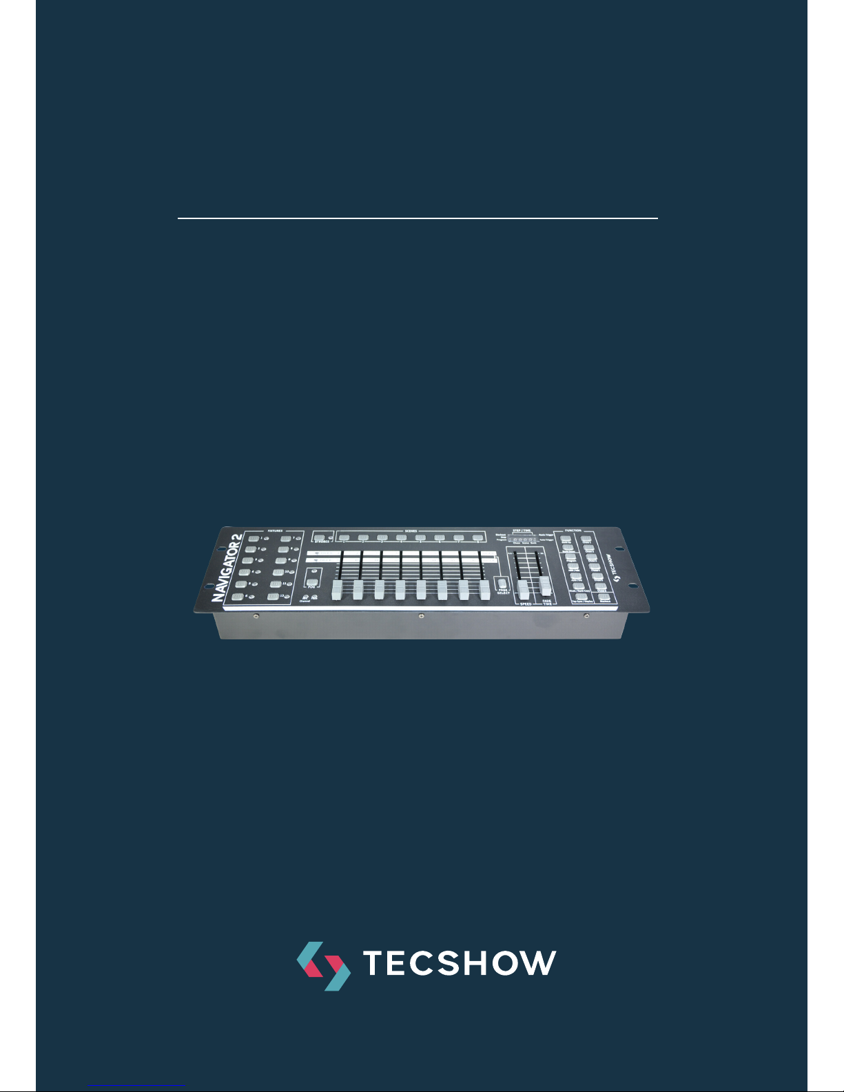
NAV I GATO R 2
DMX controller with 192 channels able to
control up to 12 units of 16 channels each
USER MANUAL / MANUAL DE USUARIO
PLEASE READ THE INSTRUCTIONS CAREFULLY BEFORE USE
POR FAVOR LEA LAS INSTRUCCIÓNES ANTES DE USAR
Page 2

P. 2
Tecshow Navi gator 2 |
Navigator 2
DMX controller with 192 channels able to control up
to 12 units of 16 channels each
Navigator 2 is a DMX controller with 192 channels able to control up to 12 units of 16 channels
each. The unit has a total of 30 banks with 8 programmable scenes (240 scenes max). Navigator 2
also includes an easy way of controlling strobes &
smoke machines. In the other hand it has 6 chases with 240 programmed scenes and MIDI control
over, banks, chases and blackout. Navigator´s new
generation is here!
Specications
Interface
• 4-digit LED display
• 8 faders for manual control - 2 pages
• Blackout button
• Strobe and Smoke machine button
Features
• 192 DMX channels - Up to 12 units of 16 DMX
channels each
• 30 banks of 8 programmable scenes
• 6 chases with 240 programmable scenes of 30
banks
• Assignable fade time
• Smoke machine input & shutter button
Connections
• 1 XLR-3 DMX Output connector
• 1 DIN connector: Smoke machine
• 1 Strobe connector
• 1 Midi Input
• 1 Power Input
Physical
• Dimensions: 483x171x89 mm. / 19x6.7x3.5 in.
• Weight: 2.6 Kg. / 5.7 Lbs.
1. OVERVIEW
English version
Page 3
P. 3
| Tecshow Navi gator 2
English version
2. BEFORE YOU BEGIN
Safety Instructions
Warning
• Always connect the product to a grounded
circuit to avoid the risk of electrocution. Make
sure the power cord is not crimped or damaged.
Check the device and the power-cord from time
to time.
• Always disconnect the product from the power
source before cleaning it or replacing the fuse.
• Never try to repair the product. This device contains no user-serviceable parts. Refer servicing
to qualied technicians only. Repairs carried
out by untrained people can lead to damage or
malfunction. Make sure there are no ammable
materials close to the product when it is operating.
• Make sure the voltage of the power source used
for the product is within the range stated on the
label or on rear panel of the product.
• Never connect the product to a dimmer or a
rheostat.
• Keep the device far away from children.
Important
• This device falls under protection class I. Therefore it is essential to connect the yellow/green
conductor to earth.
• In the event of a serious operating problem,
stop using the product immediately.
• Do not switch the device on and o in short
intervals, as this would reduce the device’s life.
• Only use device indoor, avoid contact with water or other liquids.
• Always carry the product by its mounting sides.
• Always disconnect power from the mains, when
device is not used or before cleaning!
• Only handle the power-cord by the plug. Never
pull out the plug by tugging the power-cord.
• Never let the power-cord come into contact
with other cables! Handle the power-cord and
all connections with the mains with particular
caution!
• Make sure that the device is not exposed to
extreme heat, moisture or dust.
• If device is dropped or struck, disconnect mains
power supply immediately. Have a qualied
engineer inspect for safety before operating.
• For replacement use fuses of same type and
rating only.
Unpacking instructions
Immediately upon receiving this product, carefully unpack the carton and check the contents to
ensure that all parts are present, and have been
received in good condition.
What’s included
• Controller
• External Power Supply
For your own safety, please read
this user manual carefully before
your initially start-up.
Page 4
P. 4
Tecshow Navi gator 2 |
3. DESCRIPTION OF THE DEVICE
English version
Features
• Universal DMX-512 controller
• Controls up to 192 DMX channels; up to 12
intelligent lights with 16 channels each
• 30 banks of 8 scenes, 240 scenes max
• 6 sets of chases containing 240 scenes
• Fog & strobe control buttons
• Patch mode: Each xture free assignable
channels
• Programmable Speed and Fade time
• Reversible sliders
• Sequential linking of chases
• Re-assignable channels
• Music-controlled, tap-sync and auto run
• Polarity selector
• 3HE (3U) 19" rack mount
• Output connector: 3 and 5 pole XLR female
• MIDI compatible
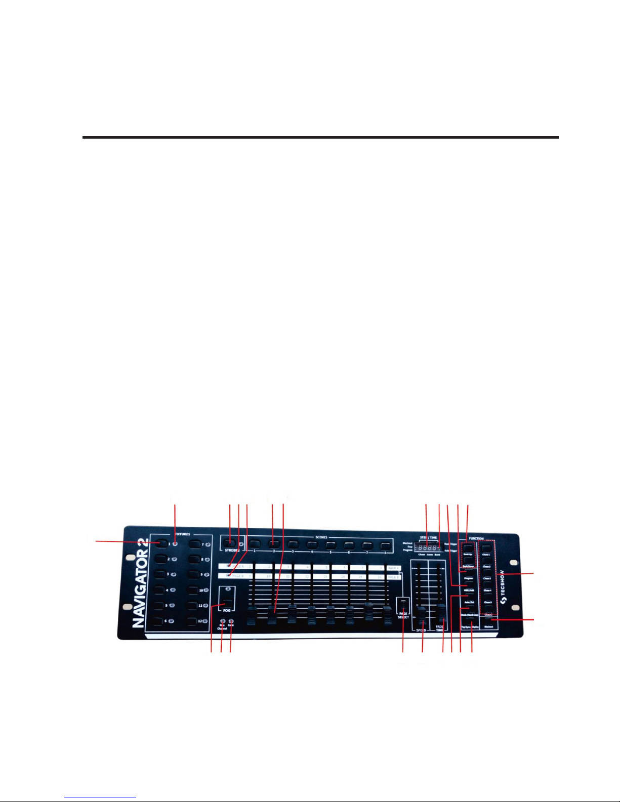
Overview
1
2 3 4 5 6 7
13
14
18
9
15
19
10
16
20
11
17
21122223
8
Page 5

P. 5
| Tecshow Navi gator 2
English version
1. Fixture select buttons To select xtures for
setting, programming or recording.
2. Fixture indicator LED's Indicates the xtures
currently selected.
3. Strobe button + LED Used for strobes.
4. Page A Indicator LED represents Ch 1~8 range
selected.
5. Page BIndicator LED represents Ch 9~16 range
selected.
6. Scene select buttons Universal bump buttons
representing scene location for storage and
selection.
7. Channel faders For adjusting DMX values, Ch
1~8 can be adjusted immediately, aer pressing
the respective xture select button, Ch 9~16
aer pressing the Page select button.
8. LCD display window Status window displays
pertinent operational data.
9. Mode Indicator LED’S Provides operating
mode status, (manual, music or auto).
10. Midi/Add button Activates MIDI external con-
trol and also used to conrm the record/save
process.
11. Program button Activates program mode.
12. Bank Up /Down button Press the Up/Down
button to select from 30 banks.
13. Chase buttons Chase memory 1 ~ 6; These
buttons are used for activating the chase of
programmed scenes.
14. Blackout button Press this button to enable or
disable relevant DMX output. When its LED is lit,
that means the relevant DMX output is disabled.
Press this button again the LED will be “o”,
that means the DMX output is reactivated.
15. Fog button + Heat Ready LED This button is
used to control the Fog machine. Relevant LED
will show you the working state (READY).
16. Reverse Channel LED Indicates reverse chan-
nel programming mode
17. Fade LED Indicates fade programming mode
18. Page select button Used to select page be-
tween PageA(I-8) and Page B (9-16).
19. Speed fader This will adjust the hold time of
a scene or a step within a chase (range of 0.1
second to 10 minutes).
20. Fade Time fader Used to adjust the fade time.
Fade time is the amount of time it takes for a
xture (or xtures ) to Move from one position
to another,for the dimmer to fade in or fade
out.
21. Auto/Del button Activates Music mode or to
delete scenes or chases during programming
22. Music/Bank Copy button Activates Music
mode or as the copy command during programming
23. Tapsync/Display button Used to create a
standard beat or to change the value mode
between % and 0-255.
24. MIDI Control In MIDI input port for external
triggering of banks, scenes, chases, and blackout using a MIDI device
25. DMX polarity switch May be used to change
signal polarity
26. DMX Control Out 3-pin DMX output connector
27. Power DC In DC Input jack Main power feed
28. Strobe Control Out ¼-inch mono port for con-
necting to one or more strobes in a daisy chain.
29. Fog Control Out 5-pin DIM port for connecting
to one or more fog machines.
30. ON/OFF power switch Turns the controller on
and o.
25
27
29
24
26
28
30
Page 6
P. 6
Tecshow Navi gator 2 |
English version
4. INSTALLATION
5. SETUP AND OPERATION
Remove all packing materials from the xture.
Check that all foam and plastic padding is removed. Screw the equipment into a 19" rack, can
be mounted in any position; make sure adequate
ventilation is provided around the product.
Always disconnect from electric mains power
supply before cleaning or servicing.
Resetting The System Warning
This will reset the controller to its factory defaults.
This will erase all programs and settings.
1) Turn o the unit.
2) Press and hold BANK UPand AUTO/DEL.
3) Turn on power to the unit (while still holding
BANK UPand AUTO/DEL).
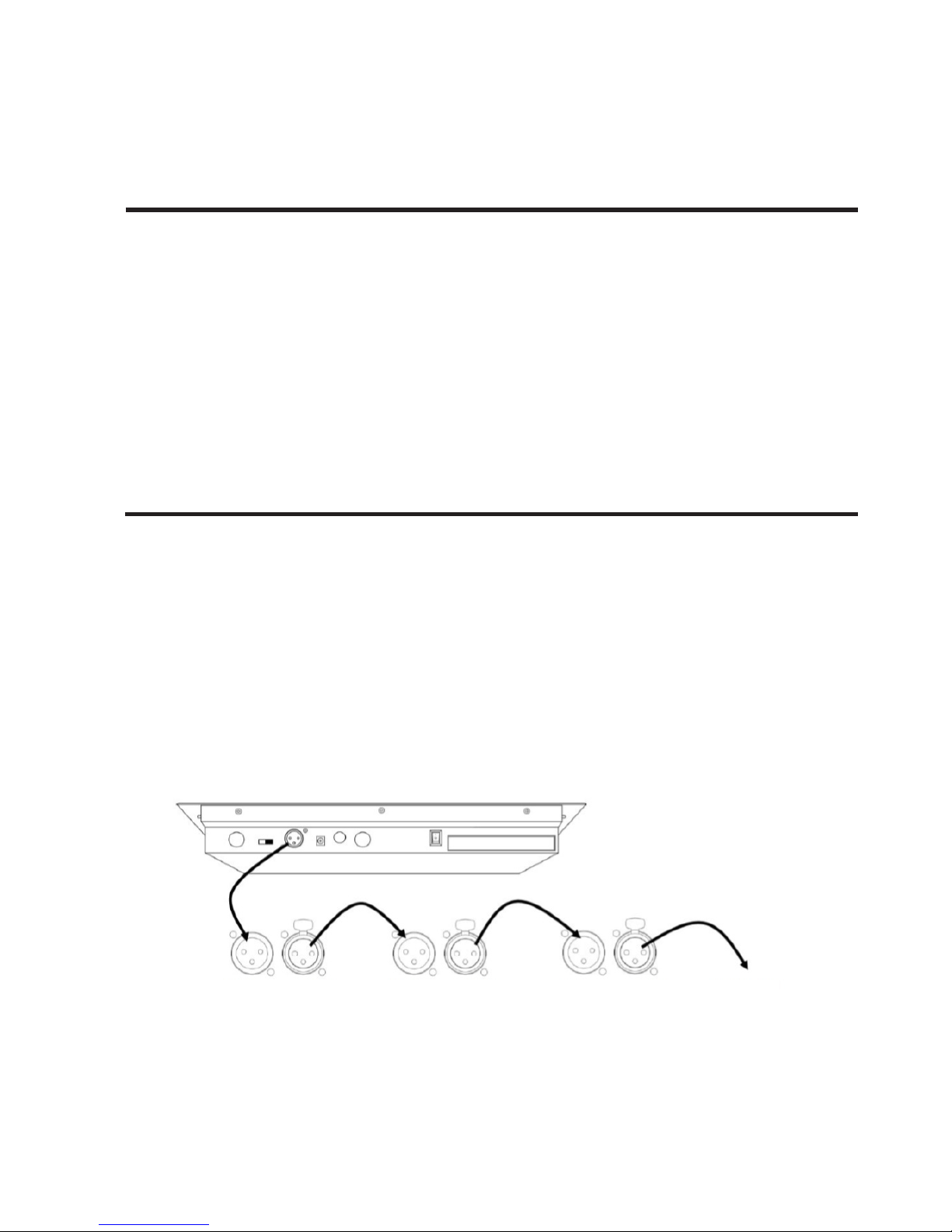
DMX Cabling
DMX cabling is required to get DMX values from the
board to the products. Connect the DMX cable from
DMX Out of the board to DMX In of the rst product
in the rig. Then connect another DMX cable from
DMX Out of the rst product in the rig to DMX In of
the next product.
Continue connecting until all the products are connected like below picture:
DMX
In
DMX
In
DMX
In
DMX
Out
DMX
Out
DMX
Out
Additional
Products
1st Product 2nd Product 3rd Product
Page 7
P. 7
| Tecshow Navi gator 2
English version
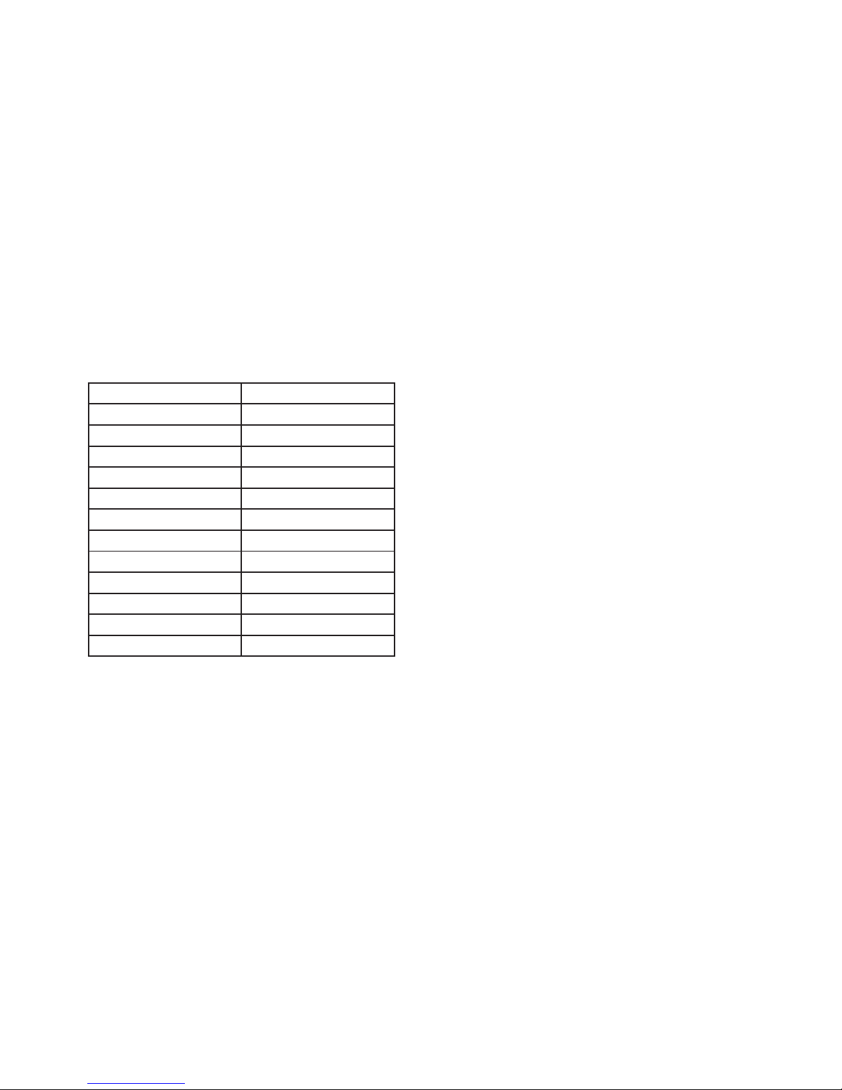
DMX Addressing
The board controls lights with specic DMX addresses and the lights must be addressed correctly
for the board to control them. More than one light
can have the same DMX address, but lights with
the same DMX address should be the same type of
light. Below is a chart showing the DMX addresses
ranges with their corresponding xture buttons.
DMX Addressing Chart
Aer the products are addressed, the board controls them with the <FIXTURES> buttons. For
example:
• Any product or products addressed at 49 are
controlled with <FIXTURES 4>.
• Any product or products addressed at 145 are
controlled with <FIXTURES 10>.
Faders and Pages
This xture has 8 channel faders on 2 fader pages
for a total of 16 channels. Faders control dierent
DMX addresses depending on which page is active
and which xture button is pressed. Pages are a
method for controlling 16 channels with only 8
channel faders. Toggling between pages toggles between two DMX addresses for the fader. When Page
A is active, the faders are numbered 1–8. When
Page B is active, the faders are numbered 9–16.
The <Page Select> button toggles between active
pages. The Page A and Page B LEDs indicate which
page is active. When Page A is active, the channel
faders control the rst 8 DMX addresses of the
selected light. When Page B is active, the channel
faders control the second 8 DMX addresses of the
selected light.
Fader DMX Addresses
The default fader DMX addresses are determined by
the combination of <FIXTURES> buttons and Page
A or Page B. For example:
• When <FIXTURES 1> is selected, the default
DMX addresses of the channel faders are 1–16.
DMX 1–8 when PageAis active and DMX 9–16
when Page B is active.
• When <FIXTURES 7> is selected, the default
DMX addresses of the channel faders are
97–112. DMX 97–104 when PageAis active and
DMX 105–112 when Page B is active.
When 2 xture buttons are selected each fader has
2 dierent default DMX addresses. For example:
• When <FIXTURES 1> and <FIXTURES 7> are
selected, channel fader 1 has DMX addresses of
both 1 and 97.
Fader Customizations
Fader customizations are very powerful tools, but
are not required. This xture can control a substantial lighting rig without any fader customization.
Fader customization is one of two things:
• Fader assignment which changes the default
DMX address of a channel fader.
• Fader reversal which reverses the fader output.
Fader assignment changes the DMX address of
a fader within a xture button, so that 2 lights,
assigned to dierent xture buttons and with dierent DMX channel congurations can be controlled
Address Fixture Button
1–16 <FIXTURES 1>
17–32 <FIXTURES 2>
33–48 <FIXTURES 3>
49–64 <FIXTURES 4>
65–80 <FIXTURES 5>
81–96 <FIXTURES 6>
97–112 <FIXTURES 7>
113–128 <FIXTURES 8>
12 9–144 <FIXTURES 9>
145–160 <FIXTURES 10>
161–176 <FIXTURES 11>
177–192 <FIXTURES 12>
Page 8

P. 8
Tecshow Navi gator 2 |
English version
from a single channel fader. See Creating A Fader
for more information.
Fader reversal changes the order of the DMX values
sent out as the channel fader moves. In normal
mode a channel fader sends out a higher DMX
value as it moves upward, sending out the value 0
at the bottom and 255 at the top. When a fader is
reversed, it sends out the value 255 at the bottom
and 0 at the top. See Creating A Fader Reversal for
more information. The fader LEDs indicate when a
fader has been customized or reversed.
Physical Fader Assignment
(optional setup)
Use this feature to combine or unify xture control
attributes for dierent xtures. For example; if you
were controlling 4 moving mirrors and 4 moving
yokes, the color, gobo and dimmer channels may
not line up ideally on the physical faders. Use this
function to re-assign the dimmer, color and gobo
channels to faders 1, 2 and 3. From now on you will
be able to control the same attributes on all xtures using the same fader location.
1) Press and hold PROGRAM & TAPSYNC buttons
together (1) time to access the channel assignment
mode.
2) Press a FIXTURE button that represents the xture whose faders you would like to re-assign.
3) Move the SPEED fader until you arrive at controller channel (number).
4) Move the FADE TIME fader to select the DMX
channel.
5) Press the MIDI/ADD button to conrm setting.
6) Repeat steps 3 ~ 5 as oen as necessary. If you
wish to copy a xture ’s physical assignments to
another xture , continue by following steps 7-13.
If you do not wish to do this, press and hold PROGRAM & TAPSYNC buttons (2) times to exit mode.
Example: Copying FIXTURE 1 into FIXTURE 2
7) Press and hold FIXTURE button # 1.
8) While holding button # 1 press FIXTURE button # 2.
9) While holding FIXTURE buttons # 1 and # 2, press
and hold MIDI/ADD button.
10) Release FIXTURE button # 1 rst before releasing FIXTURE button # 2.
11) Release MIDI/ADD button.
12) All FIXTURE LED indicators will ash to conrm
successful copy.
13) Press and hold PROGRAM & TAPSYNC buttons
(2) times to exit mode.
Reverse Channel Output
(optional setup)
1) Press and hold PROGRAM & TAPSYNC buttons
together (2) times to access the channel assignment
mode then press the FIXTURE button.
2) Move the SPEED fader until you arrive at the
controller channel you wish to alter.
3) Move the FADE TIME fader all the way up until N
changes to Y. If you wish to copy a xture’s reverse
channel assignments to another xture , continue
by following steps 4-10. If you do not wish to do
this, press and hold PROGRAM & TAPSYNC buttons
(1) times to exit mode.
Example: Copying FIXTURE 1 into FIXTURE 2.
4) Press and hold FIXTURE button # 1.
5) While holding button # 1 press FIXTURE button # 2.
6) While holding FIXTURE buttons # 1 and # 2, press
and hold MIDI/ADD button.
7) Release FIXTURE button # 1 rst before releasing
FIXTURE button # 2.
8) Release MIDI/ADD button.
9) All FIXTURE LED indicators will ash to conrm
successful copy.
10) Press and hold PROGRAM & TAPSYNC buttons
(1) times to exit mode.
Fade Time Assign (optional setup)
You can choose whether the board’s fade time during scene execution is implemented broadly to all
output channels or only to the Pan and Tilt move-
Page 9

P. 9
| Tecshow Navi gator 2
English version
ment channels. This is relevant because oen you
will want gobos and colors to change quickly while
not aecting the movement of the light.
1) Turn OFF the controller.
2) Hold the BLACKOUT and TAPSYNC buttons
simultaneously.
A program (bank) is a sequence of dierent scenes
(or steps) that will be called up one aer another.
This xture has 30 banks with 8 scenes each, so
saving a scene involves selecting the bank and the
scene.
Entering Program Mode
Press the PROGRAM button for 3 seconds until an
LED dot next to the label PROG blinks.
This indicates that the user is in programming mode.
Create a Scene
Ascene is a static lighting state. Scenes are stored in
banks.There are 30 bank memories on the controller and each bank can hold 8 scene memories. This
xture can save 240 scenes total.
1) Press and hold the PROGRAM button for 3 seconds.
2) Select a FIXTURE to program.
3) Compose a look by moving the FADERS. (Chang-
es in xture attribute such as colors and gobos.)
Press PAGE SELECT to access Channels 9~16 on the
faders.
4) To program another FIXTURE press the FIXTURE
button you have just nished programming then
select another FIXTURE button to program.
5) Repeat steps 2 ~ 4 until you have your look.
6) Tap MIDI/ADD button to prepare to store.
7) Choose a BANK (01~30). Use the Up and Down
3) Turn ON the controller.
4) Press the TAPSYNC button to toggle between the
two modes. Either all channels (A) or select channel
Pan & Tilt only (P)
5) Press BLACKOUT and TAPSYNC to save settings.
All LED’s will blink to conrm.
arrow Bank buttons to change if necessary.
8) Select a SCENES button to store. All LED's will
blink 3 times. The display will now display the bank
and scene number that is stored.
9) Repeat steps 2 ~ 8 to record more scenes. (Read
Important notes on the right ->)
10) To exit program mode, hold the PROGRAM
button for 3 seconds. The controller will default to a
BLACKOUT when exiting the programmer.
Edit a scene
1) Press the PROGRAM button for 3 seconds.
2) Locate the scene in the program BANK. Use
BANK UP/DOWN to navigate program banks.
3) Select the SCENE in the program BANK to edit.
4) Adjust FADERS to change the look.
5) Press the MIDI/ADD button then the SCENE but-
ton again previously selected for editing.
Scene Copy
1) Press the PROGRAM button for 3 seconds.
2) Locate the scene in the program BANK. Use
BANK UP/DOWN to navigate program banks.
3) Select the SCENE in the program BANK to copy.
4) Locate the destination scene in the program
BANK. Use BANK UP/DOWN to navigate program
banks.
5) Press the MIDI/ADD button then the new SCENE
button to copy to.
6. PROGRAMMING
Page 10

P. 1 0
Tecshow Navi gator 2 |
English version
Create a Chase
A Chase can contain 240 scenes as steps. The term
steps and scenes are used interchangeably.
1) Press and hold the PROGRAM button for 3 seconds.
2) Press the CHASE (1~6) button you wish to program.
3) Change BANK if necessary to locate a scene.
4) Select the SCENE to insert.
5) Tap the MIDI/ADD button to store. All LED’s will
ash 3 times.
6) Repeat steps 3 ~ 5 to add additional steps in the
chase. Up to 240 steps can be recorded.
7) Press and hold the PROGRAM button for 3 seconds to save the chase.
Copy Bank into Chase
1) Press and hold the PROGRAM button for 3 seconds
to enter programming mode.
2) Select the BANK to be copied using the BANK UP/
DOWN buttons.
3) Press MUSIC/BANK COPY and Midi/Add buttons at
the same time to copy.
4) Press and hold the PROGRAM button for 3 seconds
to exit programming mode.
Adding a Step to a Chase
1) Press and hold the PROGRAM button for 3 seconds
to enter programming mode.
2) Press the desired CHASE (1~6) button.
3) Press the TAPSYNC/Display and the display will
display the scene and bank number. This displays the
scene you will be adding (STEP LED must be on),
4) Use the BANK UP/DOWN buttons to scroll through
the chase and arrive at the step number for which you
would like to add or append a scene/step to.
5) Press MIDI/ADD button and one step number will
be added to the previously displayed step number.
6) Press the SCENE button that corresponds to the
scene to be copied.
7) Press MIDI/ADD button again to add the new step.
Delete Scene
1) Locate the scene in the program BANK. Use BANK
UP/DOWN to navigate program banks.
2) Press and hold the AUTO/DEL button while press-
ing the SCENE you want to delete.
Delete All Scenes
1) Press and hold the PROGRAM button and the
BANK while you turn the controller O.
Bank Copy
1) Press the PROGRAM button for 3 seconds.
2) Locate the program BANK. Use BANK UP/DOWN
to navigate program banks.
3) Press and release the MIDI/ADD button.
4) Locate the destination program BANK. Use BANK
UP/DOWN to navigate program banks.
5) Press the MUSIC/BANK-COPY button to compete
copy.
Bank Delete
1) Press and hold the PROGRAM button for 3 seconds.
2) Locate the BANK to delete. Press the AUTO/DEL
and MUSIC/BANK-COPY at the same time to delete
the Bank.
Chase Programming
A chase is created by using previously created scenes.
Scenes become steps in a chase and can be arranged
in any order you choose. It is highly recommended
that prior to programming chases for the rst time;
you delete all chases from memory. See “Delete All
Chases” for instructions.
Page 11

P. 11
| Tecshow Navi gator 2
English version
8) Press and hold the PROGRAM button for 3 seconds to exit programming mode.
Delete a Scene/Step in a Chase
1) Press and hold the PROGRAM button for 3 seconds to enter programming mode.
2) Press the desired CHASE (1~6) button that contains the scene to be deleted.
3) Press the TAPSYNC/DISPLAY button to switch
the LED display to steps.
4) Select the scene/step to be deleted using the
BANK UP/DOWN buttons.
5) Press AUTO/DEL button to delete the step/scene.
6) Press and hold PROGRAM button for 3 seconds
to exit.
Delete a Chase
1) Press and hold the PROGRAM button for 3 seconds to enter programming mode.
2) Press the CHASE button (1~6) to be deleted.
3) Press and hold the AUTO DEL button and the
respective CHASE button then release to delete the
chase. All LED’s will blink 3 times.
Delete all Chase Programs Caution!
This procedure will result in irrevocable loss of chase
step memory. The individual scenes and program
banks will be preserved. Press and hold the BANK
DOWN button and the AUTO DEL button while turn-
ing OFF the controller.
Page 12

P. 12
Tecshow Navi gator 2 |
English version
7. PLAYBACK (SCENES)
8. PLAYBACK (CHASES)
Running in Auto-Mode
1) Press and hold the AUTO DEL button until the
AUTO TRIGGER LED turns on.
2) Change BANK programs by using BANK UP/
DOWN buttons if necessary.
3) You can adjust the time between steps by moving
the SPEED fader and the duration of the step by
moving the FADE TIME fader.
4) You can change Banks while in operation by using the BANK UP/DOWN buttons.
BlackOut
The Blackout button brings all lighting output to 0
or o (also called the home position of the unit).
Auto Run Chases
1) Press any one of the CHASE buttons.
2) Press and release the Auto/Del button. The corresponding LED will blink.
3) Adjust the SPEED and FADE faders to your liking.
4) You can override the speed and fade time by tapping the TAPSYNC/DISPLAY button (three) times.
The chase will now run on the interval time of the
taps.
Music Run Chases
1) Press any one of the CHASE buttons.
2) Press and release the MUSIC/BANK COPY buttons. The corresponding LED will blink in the display.
Manual Run Scene
When power is rst turned ON, the controller will
be in manual scene mode.
1) Make sure neither MUSIC TRIGGER nor AUTO
TRIGGER LED's on the LED display are on.
2) Select the program BANK that stores the scene
you want to run manually by using the BANK UP/
DOWN.
3) Press the SCENE button to run.
Running in Sound-Mode
1) Press the MUSIC/BANK-COPY button until the
MUSIC TRIGGER LED turns on.
2) Change BANK programs by using BANK UP/
DOWN buttons if necessary.
3) Press the MUSIC/BANK-COPY to exit.
Manual Run Chases
This function allows the user to manually step
through each individual step in a chase.
1) Press and hold PROGRAM button for 3 seconds
to enter programming mode.
2) Start a chase by pressing any one of the CHASE
buttons.
3) Press the TAPSYNC/DISPLAY button to manual-
ly step through the chase.
4) Use the BANK buttons to scroll through the
chases.
5) Press and hold the PROGRAM button for 3 seconds to exit programming mode.
Page 13

P. 13
| Tecshow Navi gator 2
English version
9. MIDI OPERATION
The controller will only respond to MIDI commands
on the MIDI channel when it is set to full stop. All
MIDI control is performed using Note on commands. All other MIDI instructions are ignored. To
stop a chase, send the blackout on note.
1) Press and hold the MIDI/ADD button until the
third and fourth digits on the LED display blink.
2) Select the MIDI control channel (1~16) via the
BANK UP/DOWN buttons to set.
3) Press and hold the MIDI/ADD button to store
midi setup settings.
3) Your chase will now run to sound.
Running Sequential Chases
1) Press either AUTO DEL or MUSIC BANK COPY
buttons to select the trigger mode.
2) Press the CHASE button for each chase you wish
to playback.
3) Adjust the Chase speed by changing the SPEED
fader.
Midi note Function (turn on/o)
00-07 Scenes 1-8 in BANK 1
08 -15 Scenes 1-8 in BANK
16-23 Scenes 1-8 in BANK 3
24-31 Scenes 1-8 in BANK 4
32-39 Scenes 1-8 in BANK 5
40-47 Scenes 1-8 in BANK
48-55 Scenes 1-8 in BANK 7
56-63 Scenes 1-8 in BANK
64-71 Scenes 1-8 in BANK 9
72-79 Scenes 1-8 in BANK 10
80-87 Scenes 1-8 in BANK 11
88-95 Scenes 1-8 in BANK 12
96 -103 Scenes 1-8 in BANK 13
104-111 Scenes 1-8 in BANK 14
112-119 Scenes 1-8 in BANK 15
120 Chase1
121 Chase 2
122 Chase 3
123 Chase 4
124 Chase 5
125 Chase 6
126 Blackout
Page 14

P. 14
Tecshow Navi gator 2 |
English version
10. FOG CONTROL
11. STROBE CONTROL
To operate one or more fog machines, do the
following: 1. Connect the fog machines to the fog
control out port on the back panel.
2.Turn on the fog machine or machines.
3. Wait for the Fog LED to come on.
4. Press <Fog> to generate fog.
Note: The Fog LED indicates that the fog machine
is at maximum temperature and ready to generate
fog. When the LED is not on, the fog machine might
still generate fog, but not for the maximum rated
time.
To operate one or more strobes, do the following:
1. Connect the strobe or strobes to the strobe control out port on the back panel .
2.Turn on the strobe or strobes.
3. Press <Strobe> to start the strobe.
Note: The <Strobe> button is a momentary button. The light will strobe for as long as the button
is held down. When it is not pressed, the strobe is
dark. The LED indicator for the strobe button will
ash at the same rate as the strobe.
Page 15

P. 15
| Tecshow Navi gator 2
Versión Español
Navigator 2
Controlador DMX con 192 canales que controla hasta
12 unidades de 16 canales DMX cada una
Navigator 2 es un controlador DMX con 192 canales
capaz de controlar hasta 12 unidades de 16 canales
DMX cada una. El equipo cuenta con un total de 30
bancos con 8 escenas programables (240 escenas
máximo). Navigator 2 incluye, a su vez, 6 chases de
240 escenas y control MIDI sobre bancos, chases y
blackout. La nueva generación de la exitosa Navigator ya ha llegado y, además, permite controlar
fácilmente el estrobo y la máquina de humo.
Especicaciones
Interface
• Display LED de 4 digitos
• 8 faders para control manual - 2 páginas
• Botón directo para realización de Black Out
• Botón directo para estrobo y maquina de humo
Características
• 192 canales DMX – Hasta 12 dispositivos de 16
canales DMX
• 30 bancos de 8 escenas programables
• 6 chases con 240 escenas programables de 30
bancos
• Tiempo de fade asignable
• Entrada para máquina de humo & botón de
disparo
• Override manual
Conexiones
• 1 conector XLR de 3 pines: DMX de Salida
• 1 conector DIN: Máquina de humo
• 1 conector para el estrobo
• 1 entrada Midi
• 1 entrada de alimentación
Físico
• Dimensiones: 483x171x89 mm. / 19x6.7x3.5
pulg.
• Peso: 2.6 Kg. / 5.7 Lbs.
1. DESCRIPCIÓN
Page 16

P. 1 6
Tecshow Navi gator 2 |
2. INTRODUCCIÓN
Instrucciones de seguridad
Advertencias
• Procure la conexión a tierra del equipo para
evitar el riesgo de descarga eléctrica.
• Verique que el cable de suministro eléctrico
no se encuentre cortado o dañado. Compruebe
el estado del cable con frecuencia.
• Desconecte el equipo cuando no esté en funcionamiento o antes de realizar cualquier tarea de
mantenimiento.
• El equipo no contiene piezas que puedan ser
reparadas por el usuario. En caso de precisar
asistencia, póngase en contacto con el servicio
técnico autorizado.
• Mantenga el equipo alejado de llamas expues-
tas, líquidos y materiales inamables.
• Compruebe que el voltaje utilizado no sea
superior o inferior al indicado en el presente
manual o en el panel trasero del equipo.
• No conecte la unidad a un dimmer.
• Mantenga la unidad alejada del alcance de los
niños. No deje la unidad en funcionamiento y
sin supervisión.
• Procure seguir las instrucciones y advertencias
de seguridad del manual para garantizar el
buen estado del equipo y su funcionamiento
seguro.
Importante
• El equipo cuenta con grado de protección I, por
lo cual debe conectar el cable amarillo/verde a
tierra.
• Desconecte el equipo de inmediato si observa
un problema grave de funcionamiento. Coloque
la unidad en su embalaje original y llévelo al
servicio técnico autorizado para que lo revise.
• Evite encender y apagar la unidad constantemente, ya que puede reducir su vida útil.
• Este equipo se diseñó para uso en interiores.
Manténgalo alejado del agua u otros líquidos.
• Procure sujetar la unidad de los puntos de sujeción para transportarla.
• Utilice el cable desde el enchufe. Nunca tire del
cable para desconectar la unidad.
• No permita que el cable de suministro eléctrico
entre en contacto con otros cables. Utilice el
cable y todas las conexiones con extrema precaución.
• No permita que el equipo quede expuesto al
calor, humedad o polvo en exceso.
• No utilice el equipo si ha recibido un golpe
brusco o se ha caído. Desconéctelo de inmediato y póngase en contacto con el servicio técnico
autorizado antes de volver a utilizarlo.
• Utilice repuestos originales y del mismo tipo en
caso de ser necesario.
Instrucciones al abrir el producto
Abra el equipo con cuidado y verique que todas
las piezas se encuentren presentes y en buen
estado. En caso de que faltasen piezas o alguna no
funcionase correctamente como consecuencia de
un envío defectuoso, póngase en contacto con el
distribuidor de inmediato.
Contenido
• 1 equipo Navigator 2.
Lea atentamente el manual antes
de utilizar el equipo y procure
seguir las instrucciones. Consérvelo para futuras referencias ya que
contiene información importante
sobre el uso, la instalación y el
mantenimiento del equipo.
Versión Español
Page 17

P. 17
| Tecshow Navi gator 2
• Cable de suministro eléctrico.
• Manual del usuario.
3. DESCRIPCIÓN DEL EQUIPO
Características
• Controlador universal DMX 512 con 192 canales.
• Capaz de controlar hasta 12 unidades de 16 canales
cada una.
• 30 bancos de 8 escenas programables.
• 6 chases con 240 escenas programables.
• Teclas de control para estrobo y máquina de humo.
• Modo patch: asignación libre de canales a cada unidad.
• Tiempo de fade y velocidad asignables.
• Controles deslizadores reversibles.
• Reproducción en secuencia de chases.
• Reasignación de canales.
• Selector de polaridad
• Conectores hembra de salida XLR-5 y XLR-3.
• Estándar para instalación en rack de 3u.
• Entrada MIDI.
Overview
Versión Español
1
2 3 4 5 6 7
13
14
18
9
15
19
10
16
20
11
17
21122223
8
Page 18

P. 18
Tecshow Navi gator 2 |
1. Teclas Fixtures Seleccione o deseleccione las
unidades o xtures que desea programar, controlar o grabar.
2. Indicador luminoso El indicador se iluminará
para indicar la unidad actualmente seleccionada.
3. Tecla Strobe + indicador LED Para el uso de
estrobo.
4. Indicador de Page A El indicador se iluminará
cuando se seleccionen los canales 1-8.
5. Indicador de Page B El indicador se iluminará
cuando se seleccionen los canales 9-16.
6. Teclas Scenes Las teclas numéricas almacenan
y seleccionan escenas.
7. Faders de canales Utilice los deslizadores para
regular los valores DMX. Para los canales 1-8,
presione primero la tecla Fixture correspon-
diente. Para los canales 9-16, presione además
la tecla Page adecuada.
8. Pantalla LCD Provee información de funcio-
namiento.
9. Indicador de modo Los LEDs indican el modo
de funcionamiento actual (manual, automático,
etc).
10. Tecla Midi/Add Active el control externo de
MIDI y además permite conrmar el proceso
guardado.
11. Tecla Program Activa el modo programa.
12. Tecla Bank up/down Utilice esta tecla para
seleccionar entre los 30 bancos disponibles.
13. Teclas Chase Memoria de chases 1-6. Utilice
estas teclas para activar el chase de las escenas
programadas.
14. Tecla Blackout Habilite o deshabilite salidas
DMX. El indicador LED se iluminará cuando la
salida seleccionada esté deshabilitada. Para
habilitarla, presione la tecla y verique que el
indicador LED se apague.
15. Tecla Fog + Indicador LED de temperatura
Controle la máquina de humo. El indicador LED
indicará el estado de funcionamiento.
16. Indicador de Rev channel Señala que el modo
de programación del canal está invertido
17. Indicador de fade Señala el modo de progra-
mación fade.
18. Tecla Page select Seleccione la página de-
seada entre Page A (1-8) y Page B (9-16).
19. Fader Speed Regule el tiempo de retención
de una escena o del paso de un chase (de 0,1
segundos a 10 minutos).
20. Fader Fade time Regule el tiempo de fade, es
decir el tiempo de transición entre cada paso
de una secuencia.
21. Tecla Auto/Del Active el modo automático o
elimine escenas y chases durante la programación.
22. Tecla Music/Bank copy Active el modo Music
o copie bancos de escenas durante la programación.
23. Tecla Tapsync/Display Congure el disparador
de sincronización o modique el modo de vi-
sualización de los valores entre % y 0-255.
24. Entrada de control MIDI Puerto de entrada
MIDI para conectar una mesa y activar de forma
externa bancos, escenas, chases y blackouts.
25. Interruptor de polaridad DMX Permite modi-
car la polaridad de la señal.
26. Salida de control DMX Conector de salida de 3
pines.
27. Entrada de corriente continua Fuente de co-
rriente continua principal.
28. Salida de control de estrobo Puerto mono de
1/4'' que permite conectar uno o más estrobos
en cadena.
29. Salida de control de máquina de humo Puer-
to DIM de 5 pines que permite conectar una o
más máquinas de humo.
30. Interruptor de encendido/apagado
25
27
29
24
26
28
30
Versión Español
Page 19

P. 1 9
| Tecshow Navi gator 2
4. INSTALACIÓN
5. PUESTA EN MARCHA Y FUNCIONAMIENTO
Retire todo el material de embalaje de la unidad.
Verique que no haya quedado ningún envoltorio
plástico o gomaespuma. Instale el equipo en un
rack de 19 pulgadas. Recuerde que Navigator 2 se
puede colocar en cualquier posición, solo debe asegurarse de que reciba la ventilación necesaria para
funcionar sin inconvenientes.
Restaurar el sistema
Esta función le permite al usuario restaurar el con-
trolador a la conguración de fábrica. Se borrarán
todos los programas y conguraciones.
1) Apague la unidad.
2) Presione y mantenga las teclas BANK UP y AUTO/
DEL a la vez.
3) Encienda la unidad (con las teclas BANK UP y
AUTO/DEL aún presionadas).
Desconecte el equipo del suministro eléctrico
antes de realizar cualquier tarea de mantenimiento.
Conexión DMX
Navigator 2 requiere el cableado DMX para que los
equipos reciban valores DMX del tablero. Por lo tanto, conecte un extremo del cable DMX en la salida
DMX del controlador y el otro extremo, en la entrada DMX de la primera unidad en la serie. Luego,
conecte el extremo de otro cable DMX en la salida
DMX de la primera unidad y el otro extremo, en la
entrada DMX de la siguiente unidad en la serie.
Reitere este paso hasta conectar todas las unidades
deseadas. Para obtener más información, reérase
al siguiente diagrama:
Entrada
DMX
Entrada
DMX
Entrada
DMX
Salida
DMX
Salida
DMX
Salida
DMX
Unidades
Adicionales
Unidad 1 Unidad 2 Unidad 3
Versión Español
Page 20

P. 2 0
Tecshow Navi gator 2 |
Dirección DMX
A n de poder controlar unidades de luces, Navigator 2 utiliza direcciones DMX. Cada unidad debe
contar con su dirección DMX especíca y estas
direcciones deben asignarse correctamente para
garantizar que Navigator 2 pueda controlarlas. Si el
usuario lo desea, puede asignar la misma dirección
a varias unidades (solo si son luces del mismo tipo).
El cuadro a continuación muestra los rangos de
direcciones DMX con las teclas correspondientes en
el controlador.
Cuadro de asignación de
direcciones DMX
Una vez asignadas las direcciones DMX, podrá controlar las unidades con las teclas <FIX TURES>.
• Cualquier unidad con dirección DMX 49, se con-
trolará con la tecla <FIXTURES 4>.
• Cualquier unidad con dirección DMX 145, se
controlará con la tecla <FIXTURES 10>.
Faders y páginas
El equipo cuenta con 8 faders de canal con 2 páginas (pages) por fader para un total de 16 canales.
Los faders controlan diferentes direcciones DMX en
función de la tecla Fixture presionada o de la página en la que se encuentre.
Las páginas se utilizan para controlar los 16 canales
con tan solo 8 faders. Al alternar la página, se conmuta entre las dos direcciones DMX para el fader.
Cuando está activa la Página A (Page A), los faders
quedan numerados 1-8. Por otro lado, cuando
está activa la Página B (Page B), los faders quedan
numerados 9-16.
Con la tecla <Page Select> podrá alternar entra
las páginas activas. Los LEDs de Page A y Page B
indican la página actualmente activa. Cuando está
activa la Página A, los faders controlan las primeras
8 direcciones DMX de la luz seleccionada. Cuando
está activa la Página B, los faders controlan las últimas 8 direcciones DMX de la luz seleccionada.
Direcciones DMX de los faders
Las direcciones DMX predeterminadas se conguran con la combinación de las teclas <FIXTURES> y
Page A o Page B. Por ejemplo:
• Si selecciona la tecla <FIXTURE 1>, las direcciones DMX predeterminadas de los faders
son 1-16. Es decir, DMX 1-8 cuando está activa
la tecla Page A y DMX 9-16 cuando está activa la
tecla Page B.
• Si selecciona la tecla <FIXTURE 7>, las direcciones DMX predeterminadas de los faders son
97-112. Es decir, DMX 97-104 cuando está activa
la tecla Page A y DMX 105-112 cuando está activa la tecla Page B.
En caso de seleccionar dos teclas Fixture, cada
fader contará con dos direcciones DMX predeterminadas. Por ejemplo:
• Si selecciona las teclas <FIXTURE 1> y <FIXTURE
7>, el fader 1 tendrá las direcciones DMX 1 y 97
a la vez.
Personalización de los faders
Esta herramienta es sumamente útil, pero no necesariamente de uso obligatorio. Navigator 2 puede
Dirección Tecla Fixture
1–16 <FIXTURES 1>
17–32 <FIXTURES 2>
33–48 <FIXTURES 3>
49–64 <FIXTURES 4>
65–80 <FIXTURES 5>
81–96 <FIXTURES 6>
97–112 <FIXTURES 7>
113–128 <FIXTURES 8>
12 9–144 <FIXTURES 9>
145–160 <FIXTURES 10>
161–176 <FIXTURES 11>
177–192 <FIXTURES 12>
Versión Español
Page 21

P. 2 1
| Tecshow Navi gator 2
controlar perfectamente una cadena de unidades
sin utilizar faders personalizados.
La personalización de faders permite:
• Asignar un fader: Modica la dirección DMX
predeterminada de un fader.
• Invertir un fader: Invierte la salida del fader.
La asignación de un fader modica la dirección DMX
de un fader dentro de una tecla Fixture. De esta forma, dos unidades de luces, asignadas a diferentes
teclas y con diferentes conguraciones de canal
DMX, se pueden controlar desde un solo fader.
La inversión de un fader modica el orden de los
valores DMX enviados al desplazar el fader. En el
modo habitual, el fader envía un valor DMX más
alto a al deslizarse hacia arriba (máximo 255) y más
bajo al deslizarse hacia abajo (mínimo 0). Al estar
invertido, el fader envía el valor 255 ubicado en la
parte inferior y 0 ubicado en la parte superior.
Los indicadores LEDs correspondientes indican
cuando se ha invertido o personalizado un fader.
Asignación de un fader físico
(conguración opcional)
Utilice esta función para combinar o unicar atributos de control de una unidad en varias unidades.
Por ejemplo, si el usuario está controlando 4 espejos móviles y 4 cabezales móviles es posible que los
canales de color, gobo y dimmer no estén exactamente alineados con los faders físicos. Emplee esta
función para reasignar los canales de color, gobo y
dimmer a los faders 1, 2 y 3. De ahora en adelante,
podrá controlar los mismos atributos en todas las
unidades utilizando la misma posición de fader.
1) Presione y mantenga las teclas PROGRAM y TA-
PSYNC al mismo tiempo para acceder al modo de
asignación de canal.
2) Presione la tecla FIXTURE correspondiente con
la unidad a la cual desea reasignarle los faders.
3) Mueva el fader SPEED hasta llegar al canal
(número) del controlador.
4) Mueva el fader FADE TIME para seleccionar el
canal DMX al que lo desea asignar.
5) Presione la tecla MIDI/ADD para conrmar la
conguración.
6) Reitere los pasos 3-5 todas las veces que sean
necesarias. Si desea copiar las asignaciones físicas
de una unidad a otra, continúe con los pasos 7-13.
De lo contrario, presione y mantenga las teclas
PROGRAM y TAPSYNC dos veces para salir.
Ejemplo: Copiar unidad 1 en unidad 2.
7) Presione y mantenga la tecla FIXTURE 1.
8) Mientras mantiene presionada la tecla FIXTURE
1, presione la tecla FIXTURE 2.
9) Mientras mantiene presionadas las teclas FIX-
TURE 1 y 2, presione y mantenga la tecla MIDI/
ADD.
10) Suelte la tecla FIXTURE 1 antes de soltar la
tecla FIXTURE 2.
11) Suelte la tecla MIDI/ADD.
12) Todos los indicadores LED de las teclas FIXTURE
titilarán para conrmar que la copia se realizó correctamente.
13) Presione y mantenga la tecla PROGRAM y TAPSYNC dos veces para salir.
Salida de canal invertida
(conguración opcional)
1) Presione y mantenga las teclas PROGRAM y
TAPSYNC al mismo tiempo, dos veces para acceder
al modo de asignación de canal. Luego presione la
tecla FIXTURE.
2) Mueva el fader SPEED hasta llegar al canal
(número) del controlador que desea modicar.
3) Mueva el fader FADE TIME hacia arriba, hasta
que en la pantalla la N cambie por la Y. Si desea
copiar la asignación de canales invertidos de una
unidad a otra, continúe con los pasos 4-10. De lo
contrario, presione y mantenga las teclas PROGRAM y TAPSYNC para salir.
Ejemplo: Copiar unidad 1 en unidad 2.
4) Presione y mantenga la tecla FIXTURE 1.
5) Mientras mantiene presionada la tecla FIXTURE
1, presione la tecla FIXTURE 2.
Versión Español
Page 22

P. 2 2
Tecshow Navi gator 2 |
6) Mientras mantiene presionadas las teclas FIXTURE 1 y 2, presione y mantenga la tecla MIDI/
ADD.
7) Suelte la tecla FIXTURE 1 antes de soltar la tecla
FIXTURE 2.
8) Suelte la tecla MIDI/ADD.
9) Todos los indicadores LED de las teclas FIXTURE
titilarán para conrmar que la copia se realizó correctamente.
13) Presione y mantenga la tecla PROGRAM y TAPSYNC para salir.
Asignación de tiempo de fade
(conguración opcional)
El usuario puede seleccionar si desea apagar o encender el tiempo de fade (durante la ejecución de
escenas) en todos los canales o únicamente en los
canales de movimiento del pan y tilt. Esta función
le permite, por ejemplo, que los gobos y los colores
cambien rápidamente sin afectar el movimiento de
la unidad.
1) Apague el controlador.
2) Presione y mantenga las teclas BLACKOUT y
TAPSYNC a la vez.
3) Encienda el controlador.
4) Presione la tecla TAPSYNC para alternar entre los
dos modos: todos los canales (A) o únicamente el
pan y el tilt (P).
5) Presione las teclas BLACKOUT y TAPSYNC para
guardar los cambios. Todos los indicadores LED
titilarán para conrmar su selección.
Un programa (banco) es una secuencia de escenas
(o pasos) que se reproducen en serie. Navigator 2
cuenta con 30 bancos de 8 escenas cada uno. Por lo
tanto, para guardar una escena es necesario seleccionar el banco y la escena correctas.
Acceder al Modo Program
Presione la tecla PROGRAM por 3 segundos hasta
que titile el indicador LED ubicado junto a la palabra
PROG. Esto indicará el correcto ingreso al modo de
programación.
Crear una Escena
Una escena es una diseño de iluminación estático
que se almacena en bancos. Navigator 2 cuenta con
30 bancos de memoria de 8 escenas cada uno. El
controlador puede guardar un total de 240 escenas.
1) Presione y mantenga la tecla PROGRAM por 3
segundos.
2) Seleccione la tecla FIXTURE que desea programar.
3) Utilice los faders para crear un diseño de luces
(modique atributos como gobos, colores, etc).
Presione la tecla PAGE SELECT para acceder a los
canales 9-16 en los faders.
4) Para programar otra unidad, presione la tecla
FIXTURE seleccionada inicialmente para dar por
terminada la programación y luego presione otra
tecla FIXTURE a su elección para continuar con el
proceso.
5) Reitere los pasos 2-4 hasta obtener el diseño
deseado.
6) Presione la tecla MIDI/ADD para almacenarlo.
7) Seleccione un banco o BANK (1-30). Utilice las
6. PROGRAMACIÓN
Versión Español
Page 23

P. 2 3
| Tecshow Navi gator 2
teclas BANK UP/DOWN para desplazarse por las
escenas existentes, de ser necesario.
8) Seleccione una tecla SCENE donde almacenar
la escena. Todos los indicadores LED titilarán tres
veces.
9) Reitere los pasos 2-8 para grabar más escenas si
así lo desea.
10) Presione la tecla PROGRAM por 3 segundos
para salir. El controlador activará el modo BLACKOUT por defecto al abandonar el modo actual.
Editar una escena
1) Presione la tecla PROGRAM por 3 segundos.
2) Utilice las teclas BANK UP/DOWN para ubicar la
escena.
3) En BANK, seleccione la tecla SCENE correspon-
diente a la escena que desea editar.
4) Utilice los FADERS para modicar el diseño.
5) Presione la tecla MIDI/ADD y luego la tecla
SCENE previamente seleccionada.
Copiar una escena
1) Presione la tecla PROGRAM por 3 segundos.
2) Utilice las teclas BANK UP/DOWN para ubicar la
escena.
3) En BANK, seleccione la tecla SCENE correspon-
diente a la escena que desea copiar.
4) Utilice las teclas BANK UP/DOWN para ubicar la
escena donde se hará el copiado.
5) Presione la tecla MIDI/ADD y luego la nueva tecla
SCENE donde se hará el copiado.
Eliminar una escena
1) Utilice las teclas BANK UP/DOWN para ubicar la
escena en BANK.
2) Presione y mantenga la tecla AUTO/DEL y a la
vez la tecla SCENE correspondiente a la escena que
desea eliminar.
Eliminar todas las escenas
1) Presione y mantenga la tecla PROGRAM y el banco de escenas que desea eliminar mientras apaga el
controlador.
Copiar un banco de escenas
1) Presione la tecla PROGRAM por 3 segundos.
2) Utilice las teclas BANK UP/DOWN para ubicar el
banco de escenas que desea copiar.
3) Presione y suelte la tecla MIDI/ADD.
4) Utilice las teclas BANK UP/DOWN para ubicar el
banco donde se hará el copiado.
5) Presione la tecla MUSIC/BANK-COPY para completar el copiado.
Eliminar un banco de escenas
1) Presione la tecla PROGRAM por 3 segundos.
2) Ubique el banco que desea eliminar. Presione
las teclas AUTO/DEL y MUSIC/BANK-COPY a la vez
para completar el proceso de eliminación.
Programación de chases
Un chase se crea a partir de escenas previamente
creadas. En un chase, las escenas se vuelven pasos
y pueden guardarse en cualquier orden. Antes
de programar un chase, se recomienda eliminar
todos los chases de la memoria. Para obtener más
información diríjase al apartado “Eliminar todos los
chases”.
Crear un chase
Un chase puede contener hasta 240 escenas (como
pasos). Los términos escenas y pasos se emplean
de forma indistinta en el presente manual.
1) Presione la tecla PROGRAM por 3 segundos.
2) Presione la tecla CHASE (1-6) que desea programar.
3) Cambie de banco para ubicar una escena, en
Versión Español
Page 24

P. 2 4
Tecshow Navi gator 2 |
Versión Español
caso de que sea necesario.
4) Presione una tecla SCENE para seleccionar la
escena que desea agregar.
5) Presione la tecla MIDI/ADD para almacenarla.
Todos los indicadores LED titilarán tres veces.
6) Reitere los pasos 3-5 para agregar más escenas si
así lo desea.
7) Presione la tecla PROGRAM por 3 segundos para
almacenar el chase.
Copiar un banco en un chase
1) Presione la tecla PROGRAM por 3 segundos para
ingresar al modo de programación.
2) Utilice las teclas BANK UP/DOWN para ubicar el
banco de escenas que desea copiar.
3) Presione las teclas MUSIC/BANK-COPY y MIDI/
ADD a la vez para copiar el banco.
4) Presione la tecla PROGRAM por 3 segundos para
salir.
Agregar un paso a un chase
1) Presione la tecla PROGRAM por 3 segundos para
ingresar al modo de programación.
2) Presione la tecla CHASE (1-6) deseada.
3) Presione la tecla TAPSYNC/DISPLAY y en la
pantalla visualizará el número de paso (donde se
hará la adición) y banco. El indicador LED de STEP
se iluminará.
4) Utilice las teclas BANK UP/DOWN para desplazarse por el chase y ubicar el número de paso al
cual le agregará un paso o una escena.
5) Presione la tecla MIDI/ADD y se aumentará en
uno el número de pasos previamente visualizado.
6) Presione la tecla SCENE que corresponde a la
escena que desea copiar.
7) Presione la tecla MIDI/ADD nuevamente para
agregar un nuevo paso.
8) Presione la tecla PROGRAM por 3 segundos para
salir.
Eliminar un paso en un chase
1) Presione la tecla PROGRAM por 3 segundos para
ingresar al modo de programación.
2) Presione la tecla CHASE (1-6) que contiene el
paso por eliminar.
3) Presione la tecla TAPSYNC/DISPLAY para que la
pantalla indique el número de pasos.
4) Utilice las teclas BANK UP/DOWN para seleccionar el paso o la escena que desea eliminar.
5) Presione la tecla AUTO/DEL para eliminar el paso.
6) Presione la tecla PROGRAM por 3 segundos para
salir.
Eliminar un chase
1) Presione la tecla PROGRAM por 3 segundos para
ingresar al modo de programación.
2) Presione la tecla CHASE (1-6) que desea eliminar.
3) Presione las teclas AUTO/DEL y CHASE (1-6) por
eliminar y luego suéltelas. Todos los indicadores
LED titilarán 3 veces para conrmar la eliminación.
3) Presione y mantenga la tecla
Eliminar todos los chases
Advertencia: Este procedimiento elimina de forma
irreversible todos los pasos de la memoria. Las
escenas individuales y bancos de programas no se
verán afectados.
1) Presione y mantenga las teclas BANK DOWN y
AUTO DEL mientras apaga el controlador.
Page 25

P. 2 5
| Tecshow Navi gator 2
Versión Español
7. REPRODUCCIÓN DE ESCENAS
8. REPRODUCCIÓN DE CHASES
Ejecutar escenas en modo
automático
1) Presione la tecla AUTO/DEL hasta que se encienda el indicador LED de AUTO TRIGGER.
2) Utilice las teclas BANK UP/DOWN para desplazarse entre bancos, de ser necesario.
3) Utilice el fader SPEED para regular el tiempo
entre pasos y el fader FADE TIME para regular la
duración de los pasos.
4) Puede cambiar de banco con las teclas BANK UP/
DOWN.
Blackout
La tecla blackout apaga la emisión de luz o la con-
gura con valor de salida 0 (también denominada
posición inicial de la unidad).
Ejecutar chases en modo
automático
1) Presione una de las teclas CHASE (1-6).
2) Presione y suelte la tecla AUTO/DEL. El indicador
led correspondiente titilará.
3) Utilice los faders SPEED TIME y FADE TIME para
regular la velocidad y el fade.
4) Es posible omitir el paso anterior si presiona la
tecla TAPSYC/DISPLAY tres veces.
Ejecutar escenas de forma manual
Cuando se enciende el controlador por primera
vez, este se iniciará en modo manual de escenas.
1) Verique que los indicadores LED de MUSIC
TRIGGER y AUTO TRIGGER estén encendidos.
2) Utilice las teclas BANK UP/DOWN para seleccionar el banco que contiene la escena que desea
ejecutar manualmente.
3) Presione la tecla SCENE para ejecutarla.
Ejecutar escenas en modo
audiorítmico
1) Presione la tecla MUSIC/BANK-COPY hasta que
se encienda el indicador LED de MUSIC TRIGGER.
2) Utilice las teclas BANK UP/DOWN para desplazarse entre bancos, de ser necesario.
3) Presione la tecla MUSIC/BANK-COPY para salir.
Ejecutar chases de forma
manual
Esta función le permite al usuario pasar de forma
manual cada paso de un chase.
1) Presione la tecla PROGRAM por 3 segundos para
ingresar al modo de programación.
2) Presione la tecla CHASE (1-6) que desea reproducir.
3) Presione la tecla TAPSYC/DISPLAY para pasar de
forma manual por cada paso del chase.
4) Utilice las teclas BANK UP/DOWN para despla-
zarse entre los chases, de ser necesario.
5) Presione la tecla PROGRAM por 3 segundos
para salir.
Page 26

P. 2 6
Tecshow Navi gator 2 |
Ejecutar chases en modo
audiorítmico
1) Presione una de las teclas CHASE (1-6).
2) Presione y suelte la tecla MUSIC/BANK-COPY. El
indicador led correspondiente titilará.
3) El chase se reproducirá al ritmo de la música.
Ejecutar chases en secuencia
1) Presione las teclas AUTO/DEL o MUSIC/BANK-
COPY para seleccionar el modo trigger.
2) Presione las teclas CHASES correspondientes con
aquellos chases que desea reproducir.
3) Utilice el fader SPEED para regular la velocidad de
los chases.
9. FUNCIONES MIDI
Navigator 2 responderá a los comandos MIDI, en el
canal MIDI, si está completamente detenido. Todo
control MIDI se lleva a cabo utilizando comandos
Note on. Cualquier otro comando MIDI no será
tenido en cuenta. Para detener un chase, envíe la
nota blackout on.
Congurar la entrada MIDI
1) Presione la tecla MIDI/ADD hasta que titilen el
tercer y cuarto dígito en la pantalla LED.
2) Utilice las teclas BANK UP/DOWN para selec-
cionar el canal de control MIDI (1-16).
3) Presione y mantenga la tecla MIDI/ADD para
almacenar valores de conguración MIDI.
Nota MIDI Función (encender/apagar)
00-07 Escenas 1-8, banco 1
08 -15 Escenas 1-8, banco 2
16-23 Escenas 1-8, banco 3
24-31 Escenas 1-8, banco 4
32-39 Escenas 1-8, banco 5
40-47 Escenas 1-8, banco 6
48-55 Escenas 1-8, banco 7
56-63 Escenas 1-8, banco 8
64-71 Escenas 1-8, banco 9
72-79 Escenas 1-8, banco 10
80-87 Escenas 1-8, banco 11
88-95 Escenas 1-8, banco 12
96 -103 Escenas 1-8, banco 13
104-111 Escenas 1-8, banco 14
112-119 Escenas 1-8, banco 15
120 Chase 1
121 Chase 2
122 Chase 3
123 Chase 4
124 Chase 5
125 Chase 6
126 Blackout
Versión Español
Page 27

P. 2 7
| Tecshow Navi gator 2
10. MÁQUINA DE HUMO
11. ESTROBO
Observación: El indicador LED de FOG señala
que la máquina de humo alcanzó la temperatura
máxima y que está lista para generar humo. Si el
LED permanece apagado, es posible que la máquina genere humo de todas formas, pero lo hará por
un periodo de tiempo breve.
Observación: El estrobo funcionará solo cuando
mantenga presionada la tecla STROBE. Cuando
no la presione, la luz se apagará. El indicador LED
titilará al ritmo del estrobo.
Siga los pasos a continuación para operar máquinas de humo a través del Navigator 2.
1) Conecte las máquinas de humo a la salida de
control de máquina de humo en el panel dorsal del
controlador.
2) Encienda las máquinas de humo.
3) Aguarde a que se encienda el led indicador de la
tecla FOG.
3) Presione la tecla FOG para generar humo.
Siga los pasos a continuación para operar uno o
más estrobos a través del Navigator 2.
1) Conecte los estrobos a la salida de control de
estrobo en el panel dorsal del controlador.
2) Encienda los estrobos.
3) Aguarde a que se encienda el led indicador de la
tecla FOG.
3) Presione la tecla STROBE para iniciar los estrobos.
Observación: El proveedor no asumirá responsabilidad por los errores u omisiones del manual.
La información de este manual está sujeta a cambios sin previo aviso.
Versión Español
Page 28

P. 2 8
Tecshow Navi gator 2 |
FOR MORE INFO ON THIS PRODUCT PLEASE CHECK WWW.TEC-SHOW.COM /
PARA MAS INFORMACION SOBRE ESTE PRODUCTO VISITE WWW.TEC-SHOW.COM
 Loading...