

Page 1

P. 1
| Tecshow ET D ual
ET DUAL
Dual 2-in-1 moving head with 2 SMD LED rings
USER MANUAL / MANUAL DE USUARIO
PLEASE READ THE INSTRUCTIONS CAREFULLY BEFORE USE
POR FAVOR LEA LAS INSTRUCCIÓNES ANTES DE USAR
Page 2

P. 2
Tecshow ET D ual |
ET Dual
Dual 2-in-1 moving head with 2 SMD LED rings
ET Dual is a compact dual moving head that has
two projectors with independent tilt control and
2 LED rings. The unit is equipped with 2 RGBW
4-in-1 30W LEDs, plus 24 SMD5050 RGB LEDs in its
ring section with 24 integrated eects, achieving a
luminous output of 5400 lux at 3 meters with an 8º
beam angle. ET Dual stands out for the speed and
precision of its movements, being ideal for small
and medium scale applications, adding a striking
visual eect and great coverage to its compact and
lightweight design.
Specications
Source & Optics
• Light Sources:
• 2 30W RGBW 4-in-1 LEDs
• 24 RGB 3-in-1 SMD5050 LEDs
• LEDs life: 50,000 hours
• Beam angle: 8º
Photometric data
• Color temperature: 6500-7000K
• Flux: 5,400 lux @ 3m (10 .)
Eects & Functions
• Quad-color LED technology: Smooth RGBW mix
with no multi-colored shadows
• Independent color mixing by projector
• Two SMD LED rings
• 24 built-in LED ring programs
• Dimmer: Full range 0-100%
• Strobe eect: 1-20Hz
• Ultra-compact design
• Manual focus
• Continuous pan rotation
Movement
• Pan: Innite pan rotation
• Tilt: 185º
• Pan/Tilt ne
• Auto repositioning
Control
• DMX channels: 13/21
• Operational modes: DMX, Master/Slave,
Sound-active & Auto-run
Physical
• DMX connectors: 2 XLR connectors (XLR-3 In
and Out)
• Power supply input
• 4-digit LCD display
• Dimensions: 270x170x310 mm. / 10.6x6.7x12.2 in.
• Weight: 3.6 Kg. / 7.9 Lbs.
1. OVERVIEW
English version
Page 3

P. 3
| Tecshow ET D ual
English version
To optimize the performance of this product, please
read these operating instructions carefully to
familiarize yourself with the basic operations of this
unit. These instructions contain important safety
information regarding the use and maintenance of
this unit. Please keep this manual with the unit, for
future reference.
Safety Precautions
For your own personal safety, please read and
understand this manual completely before you
attempt to install or operate this unit.
• To reduce the risk of electrical shock or re, do
not expose this unit rain or moisture
• Do not spill water or other liquids into or on to
your unit.
• Do not attempt to operate this unit if the power
cord has been frayed or broken.
• Do not attempt to remove or break o the
ground prong from the electrical cord. This
prong is used to reduce the risk of electrical
shock and re in case of an internal short.
• Disconnect from main power before making
any type of connection.
• Do not remove the cover under any conditions.
There are no user serviceable parts inside.
• Never operate this unit when it’s cover is removed.
• Always be sure to mount this unit in an area
that will allow proper ventilation. Allow about
15cm between this device and a wall.
• Do not attempt to operate this unit, if it becomes damaged.
• This unit is intended for indoor use only, use of
this product out- doors voids all warranties.
• Always mount this unit in safe and stable matter.
• Power-supply cords should be routed so that
they are not likely to be walked on or pinched
by items placed upon or against them, paying
particular attention to cords at plugs, conven-
ience receptacles, and the point where they
exit from the appliance.
• Cleaning -The xture should be cleaned only
as recommended by the manufacturer.
• Heat -This xture should be situated away
from heat sources such as radiators, heat registers, stoves, or other appliances (including
ampliers) that produce heat.
• The xture should be serviced by qualied
service personnel when:
a. Objects have fallen, or liquid has been
spilled into the appliance.
b. The appliance has been exposed to rain or
water.
c. The appliance does not appear to operate
normally or exhibits a marked change in
performance.
2. GENERAL INSTRUCTIONS
Page 4
P. 4
Tecshow ET D ual |
English version
When installing the unit, the trussing or area of
installation must be able to hold 10 times the
weight without any deformation. When installing
the unit must be secured with a secondary safety
attachment, e.g. and appropriate safety cable. Never stand directly below the unit when mounting,
removing, or servicing the unit.
Overhead mounting requires extensive experience,
including calculating working load limits, installation material being used, and periodic safety
inspection of all installation material and unit. If
you lack these qualications, do not attempt the
installation yourself.
The installation should be checked by a skilled
person once a year.
The xture is fully operational in three dierent
mounting positions, hanging upside-down from
a ceiling, set on a at level surface, or on its side
attached to trussing. Be sure this xture is kept
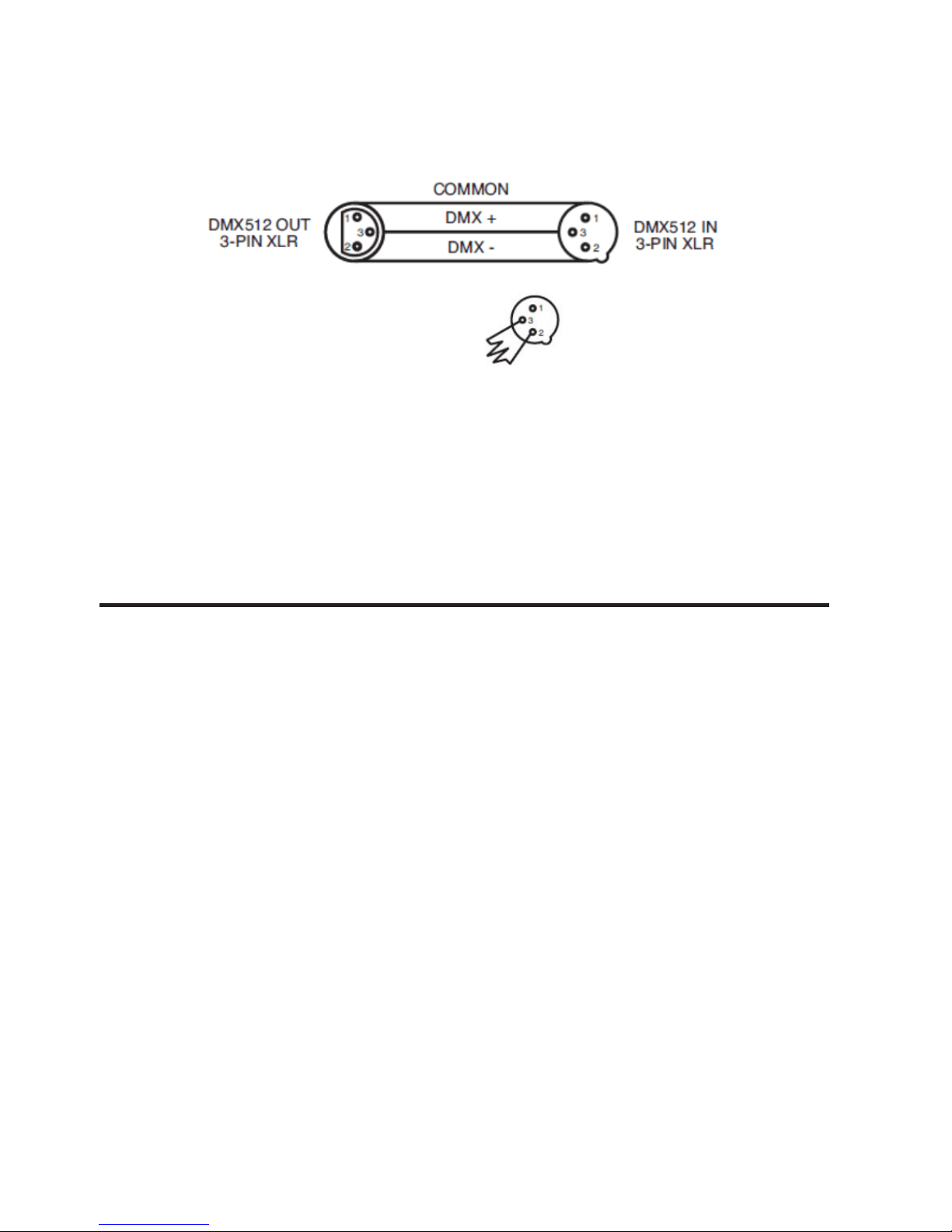
Notice: Be sure to follow gures two and three
when making your own cables. Do not use the
ground lug on the XLR connector. Do not connect
the cable’s shield conductor to the ground lug or
allow the shield conductor to come in contact with
the XLR’s outer casing. Grounding the shield could
cause a short circuit and erratic behavior.
at least 0.5m away from any ammable materials
(decoration etc.). Always use and install the sup-
plied safety cable as a safety measure to prevent
accidental damage and/or injury in the event the
clamp fails.
Notice: The suitable environmental temperature for
this lighting xture is between -25˚ C to 45˚ C. Do not
place this lighting xture in an environment where
the temperatures are under or above the tempera-
tures stated above. This will allow the xture to run
at its best and help prolong the xture life.
Screw one clamp via a M12 screw and nut to the included bracket. Attach the bracket using the includ-
ed screws to the bottom of the xture. Attach the
eyehole screw to the bottom of the base and pull
the safety-cable through the screw and over the
trussing system or a safe xation spot. Insert the
end in the carabine and tighten the safety screw.
3. MOUNTING
4. DMX SET UP
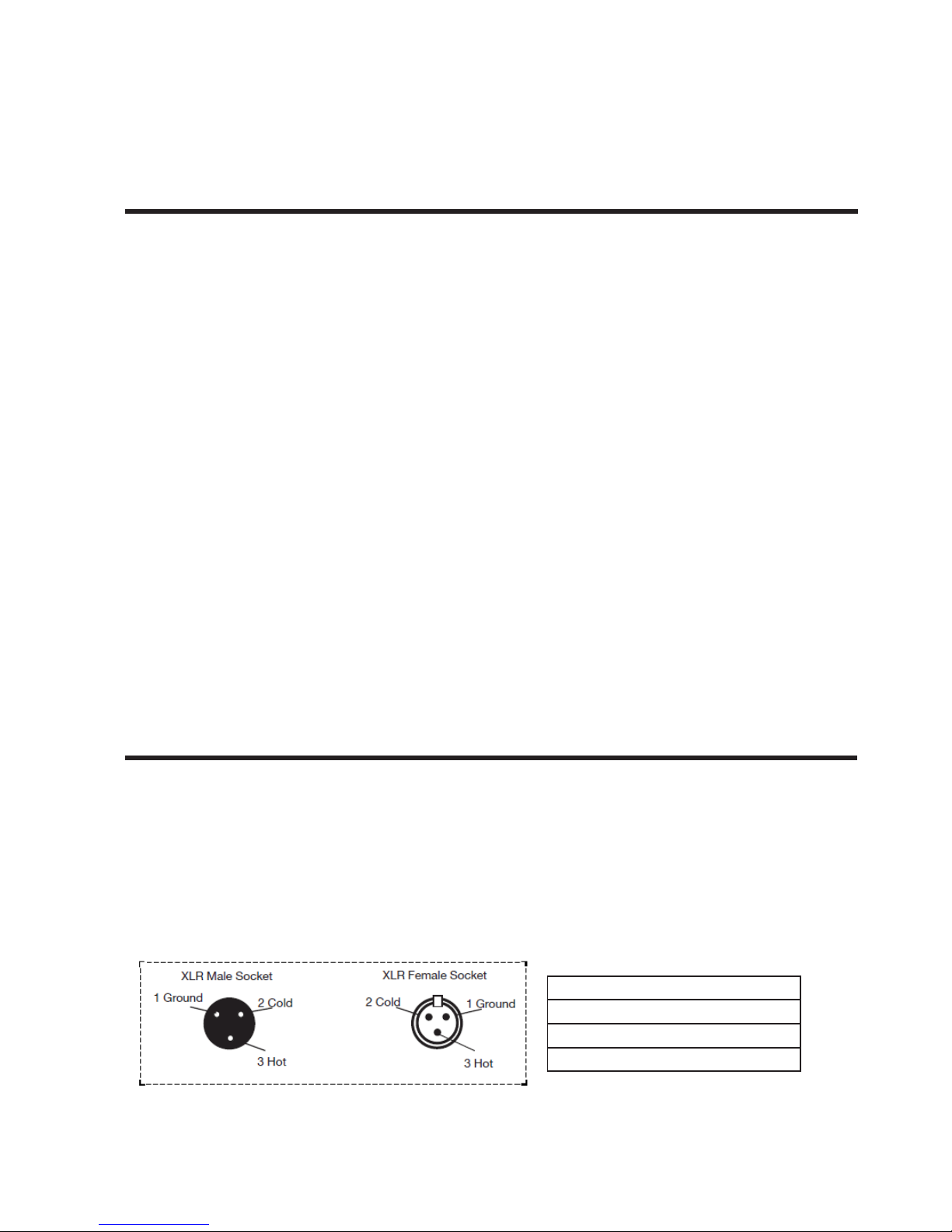
XLR Pin Conguration
Pin 1: Ground
Pin 2: Data Compliment (negative)
Pin 3: Data True (positive)
Page 5
P. 5
| Tecshow ET D ual
English version
DMX Address Mode
This option is for DMX Address setting, press MENU
to select Addr, press Enter to start setting, Using UP
or Down to choose your desired Address No., Then
press Enter to conrm.
DMX Channel Mode
This option is for setting the unit’s channel mode.
Press MENU to select Chnd, Then press Enter to
start setting, UP or DOWN to select the channel
mode, successively 13CH and 21CH, then press
Enter again to conrm your selection.
• 13CH: 13Channel mode
• 21CH: 21Channel mode
Master/Slave Mode
This option is for setting the unit’s Master-slave
mode. Press MENU to select SLnd, Then press Enter
to start setting, there will show MAST, SL1, Press
UP or DOWN to choose Master or slave, then press
Enter again to conrm your selection.
Special Note: Line Termination. When longer runs
of cable are used, you may need to use a terminator on the last unit to avoid erratic behavior. A
terminator is a 110-120 ohm 1/4 watt resistor which
is connected between pins 2 and 3 of a male XLR
connector (DATA + and DATA -). This unit is inserted
in the female XLR connector of the last unit in your
daisy chain to terminate the line. Using a cable
terminator will decrease the possibilities of erratic
behavior.
• MAST: Choose the device as master
• SL1: Choose the device as slave
Show Mode
This option is for setting Auto Or Sound Mode, Press
MENU to select ShNd, press Enter to start setting,
Auto & SoUn will show, Choose Auto, the xture will
auto running, Choose SoUn, The xture will running as the music. then press Enter to conrm your
choose.
Sound Sensitive
This option is for adjusting sound sensibility. Press
MENU, select SEns, press Enter to start setting, UP
and Down to adjust sound sensibility from 0-100,
then press Enter to conrm your choose.
Pan Reverse
This option is set to reverse the Pan direction. Press
MENU, select Pan, press Enter to start setting, UP
and Down to select no or Yes, then press Enter to
Termination reduces signal errors and
avoids signal transmission problems
and interference. It is always asvisable
to connect a DMX termnal (Resistances
120 Ohm 1/4W) between PIN 2 (DMX-) and PIN 3
(DMX +) of the last xture.
5. DISPLAY MENU
Page 6

P. 6
Tecshow ET D ual |
English version
conrm your choose.
Tilt 1 Reverse
This option is set to reverse the Tilt 1 direction.
Press MENU, select 1tiL, press Enter to start setting,
UP and Down to select no or Yes, then press Enter
to conrm your choose.
Tilt 2 Reverse
This option is set to reverse the Tilt 2 direction.
Press MENU, select 2tiL, press Enter to start setting,
UP and Down to select no or Yes, then press Enter
to conrm your choose.
Display Reverse
This option is the reverse direction of the display
panel. Press MENU, select DISP, press Enter to dSIP
and it will reverse directions, then press Enter to
conrm your choose.
Auto Test
This option is the Auto test the xture. Press MENU,
select test, press Enter, the xture will test.
Reset
Press MENU, select rSEt, press Enter key and wait
for 1-3seconds, The light will be reset.
How to operate Motor Oset
function
Press “MENU” button , then press “ENTER” for 5 sec-
onds at least , It will into the Oset Mode, Press UP
and DOWN to adjust the motor position of Pan, Tilt.
DMX mode
6. DMX CHANNEL
Mode 1(13) Function
1 Pan
2 Pan Endless Rotate
3 Tilt 1
4 Tilt 2
5 Pan/Tilt Speed
6 Strobe
7 Dimmer
8 Red
9 Green
10 Blue
11 White
12 Halo Eect
13 Auto Mode
Page 7

P. 7
| Tecshow ET D ual
English version
Mode 2(21) Function
1 Pan
2 Pan Fine
3 Pan Endless Rotate
4 Tilt 1
5 Tilt 1 Fine
6 Tilt 2
7 Tilt 2 Fine
8 Pan/Tilt Speed
9 Strobe
10 Dimmer
11 LED 1 Red
12 LED 1 Green
13 LED 1 Blue
14 LED 1 White
15 LED 2 Red
16 LED 2 Green
17 LED 2 Blue
18 LED 2 White
19 Halo 1 Eect
20 Halo 2 Eect
21 Auto Mode
Function Value Percent / Setting Mode 13CH Mode 21CH
Pan 000-255 0~100% 1 1
Pan Fine 000-255 0~100% 2
Pan Endless Rotate
000-015
016 -125
12 5-145
146 -255
No
Pan Clockwise Rotate from fast to slow
Stop
Pan Counter-clockwise Rotate from slow to fast
2 3
Tilt 1 000-255 0~100% 3 4
Tilt 1 Fine 000-255 0~100% 5
Tilt 2 000-255 0~100% 4 6
Tilt 2 Fine 000-255 0~100% 7
Pan/Tilt Speed 000-255 Fast -> Slow (Pan Endless rotate speed control
is invalid in this Channel)
5 8
Page 8

P. 8
Tecshow ET D ual |
English version
Strobe
000-000
001-255
Open
Strobe from Slow to Fast
6 9
Dimmer 000-255 0~100% 7 10
LED (1) Red 000-255 0~100% 8 11
LED (1) Green 000-255 0~100% 9 12
LED (1) Blue 000-255 0~100% 10 13
LED (1) White 000-255 0~100% 11 14
LED 2 Red 000-255 0 ~100 % 15
LED 2 Green 000-255 0 ~100% 16
LED 2 Blue 000-255 0~100% 17
LED 2 White 000-255 0~100% 18
Halo (1) Eect
000-005
006-011
012-017
018-023
024-029
030-035
036-0 41
042-047
048-053
054-059
060-065
066-071
072-077
078-083
084-089
090-095
096-101
102-107
108-113
114-119
120-125
126-131
132-179
180-217
218-255
Closed
Part 1 Red
Part 1 Green
Part 1 Blue
Part 2 Red
Part 2 Green
Part 2 Blue
Part 3 Red
Part 3 Green
Part 3 Blue
Part 4 Red
Part 4 Green
Part 4 Blue
Opposite Two Part Red
Opposite Two Part Green
Opposite Two Part Blue
The other Opposite Two Part Red
The other Opposite Two Part Green
The other Opposite Two Part Blue
All Red
All Green
All Blue
All Full color
Color Gradual Change
Color Jump Change
12 19
Halo 2 Eect
000-005
006-011
012-017
018-023
024-029
030-035
Closed
Part 1 Red
Part 1 Green
Part 1 Blue
Part 2 Red
Part 2 Green
20
Page 9

P. 9
| Tecshow ET D ual
English version
036-0 41
042-047
048-053
054-059
060-065
066-071
072-077
078-083
084-089
090-095
096-101
102-107
108-113
114-119
120-125
126-131
132-179
180-217
218-255
Part 2 Blue
Part 3 Red
Part 3 Green
Part 3 Blue
Part 4 Red
Part 4 Green
Part 4 Blue
Opposite Two Part Red
Opposite Two Part Green
Opposite Two Part Blue
The other Opposite Two Part Red
The other Opposite Two Part Green
The other Opposite Two Part Blue
All Red
All Green
All Blue
All Full color
Color Gradual Change
Color Jump Change
Auto Mode
000-027
028-082
08 3-112
113-168
169-199
200-239
240-255
No Function
Sound Activity
No Function
Auto Run
No Function
Reset
No Function
13 21
Locate and remove the unit’s power cord. Once
the cord has been removed located the fuse holder
located inside the power socket. Insert a at-head
screw driver into the power socket and gently pry
out the fuse holder. Remove the bad fuse and replace with a new one. The fuse holder has a built-in
socket for a spare fuse be sure not to confuse the
spare fuse with active fuse.
Warning: If aer replacing the fuse you continue
to blow fuses, STOP using the unit. Contact customer support for further instructions. Continuing
to use the unit may cause serious damage.
7. FUSE REPLACEMENT
Page 10

P. 1 0
Tecshow ET D ual |
Fixture Cleaning: Due to fog residue, smoke, and
dust cleaning the internal and external lenses
should be carried out periodically to optimize light
output.
1. Use normal glass cleaner and a so cloth to
wipe down the out- side casing.
2. Use a brush to wipe down the cooling vents and
fan grill.
3. Clean the external optics with glass cleaner and
a so cloth every 20 days.
4. Clean the internal optics with glass cleaner and
a so cloth every 30-60 days.
5. Always be sure to dry all parts completely before plugging the unit back in.
Listed below is a problem that you may encounter,
with a solution. No light output from the unit;
1. Be sure the fuse has not blown. The fuse is
located on the rear panel inside the power
socket. See Fuse Replacement.
2. Be sure the fuse holder is completely and properly seated.
Auto Sensing Voltage:
This xture contains a automatic voltage switch,
which will auto sense the voltage when it is plugged
into the power source.
Please Note:
Specications and improvements in the design
of this unit and this manual are subject to change
without any prior written notice.
8. CLEANING
9. TROUBLE SHOOTING
Design and product specications are subject to change without prior notice.
English version
Page 11

P. 11
| Tecshow ET D ual
ET Dual
Cabezal móvil dual 2-in-1 con 2 anillos LED SMD
ET Dual es un compacto cabezal móvil dual que
cuenta con dos proyectores con control de tilt
independiente y 2 anillos LED. La unidad está equipada con 2 LEDs RGBW 4-en-1 de 30W, más 24 LEDs
SMD5050 RGB en su sección de anillos con 24 efectos integrados, logrando un rendimiento luminoso
de 5400 lux a 3 metros con un ángulo de haz de 8º.
ET Dual se destaca por la velocidad y precisión de
sus movimientos, siendo ideal para aplicaciones
de pequeña y mediana escala, sumandole un
impactante efecto visual y una gran cobertura a su
compacto y liviano diseño.
Especicaciones
Fuente & Óptica
• Fuente de luz: 2 LEDs RGBW 4-en-1 de 30W
• 24 LEDs SMD5050 RGB 3-en-1
• Vida útil promedio: 50.000 horas
• Ángulo de haz: 8º
Información fotométrica
• Temperatura color: 6500-7000K
• Flux: 5.400 lux @ 3m (10 pies)
Efectos y Funciones
• Tecnología LED de cuatro colores: Mezcla RGBW
suave sin sombras multicolor
• Mezcla de color independiente por proyector
• Dos anillos LED SMD RGB
• Anillos LED de control independiente con 24
programas integrados
• Dimmer: Rango completo 0-100%
• Efecto Estrobo: 1-20Hz
• Diseño ultra-compacto
• Foco manual
• Pan ilimitado
Movimiento
• Pan ilimitado
• Tilt: 185°
• Pan/Tilt nos
• Auto reposicionamiento
Control
• Canales DMX: 13/21
• Modos de operación: DMX, audioritmico, auto-
matico y Maestro/Esclavo
Físico
• Conectores DMX: 2 conectores XLR (XLR-3 de
entrada & salida)
• Conector de alimentación
• Display LCD de 4 digitos
• Dimensiones: 270x170x310 mm. / 10,6x6,7x12,2
pulg.
• Peso: 3,6 Kg. / 7,9 Lbs.
1. DESCRIPCIÓN
Versión Español
Page 12

P. 12
Tecshow ET D ual |
Versión Español
Lea atentamente el manual antes de utilizar el equipo
y procure familiarizarse con las funciones básicas para
optimizar el rendimiento de su ET Dual. El presente
manual contiene información importante sobre el
uso, la instalación y el mantenimiento del equipo.
Conserve este manual para futuras referencias.
Precauciones de seguridad
Por cuestiones de seguridad, procure leer y
comprender las indicaciones del manual antes
de instalar o utilizar el equipo.
• Proteja el equipo de la lluvia y la humedad para
reducir el riesgo de descarga eléctrica.
• Evite el ingreso de líquidos, objetos de metal o
sustancias inamables dentro del equipo.
• No opere esta unidad si el cable de alimenta-
ción está dañado o deshilachado.
• No obstruya ni elimine el contacto a tierra del
cable de alimentación. Esa clavija reduce el
riesgo de descarga eléctrica e incendios en
caso de corto circuito.
• Desconecte el equipo del suministro eléctrico
antes de realizar cualquier tarea de mante-
nimiento.
• No abra la cubierta del equipo bajo ninguna
circunstancia. El equipo no contiene piezas que
puedan ser reparadas por el usuario.
• Nunca opere este equipo si la cubierta no está
apropiadamente cerrada.
• Procure instalar el equipo en un ambiente con
buena ventilación. Mantenga una distancia mínima de 15 cm con otros objetos o supercies.
• No intente poner en funcionamiento la unidad
si se encuentra dañada.
• Este equipo se diseñó para uso en interiores. Su
uso en exteriores invalida la garantía.
• Instale el equipo sobre una supercie plana y
segura.
• Los cables de alimentación deben estar protegidos de forma tal que no sea posible pisarlos
ni engancharlos con objetos ubicados sobre o
cerca ellos. Preste especial atención al enchufe y su punto de salida del equipo.
• Se recomienda la limpieza regular del equipo
según las recomendaciones del fabricante.
• Mantenga el equipo alejado de fuentes de ca-
lor como radiadores, hornos, amplicadores u
otros dispositivos que generen calor.
• Personal de servicio autorizado debe revisar
el equipo si: Se han introducido objetos o
líquidos en el interior del equipo.
2. INSTRUCCIONES DE SEGURIDAD
Page 13

P. 13
| Tecshow ET D ual
Versión Español
Para garantizar una instalación segura, la estructura en la que se je el equipo debe poder soportar
diez veces su peso sin sufrir deformaciones. Utilice
un accesorio de seguridad adicional, como un cable
de seguridad durante la instalación. Evite situarse
debajo del equipo para realizar su montaje, des-
montaje o mantenimiento.
Para realizar un montaje en altura se requiere de
experiencia y conocimientos previos para calcular
los límites de peso, los materiales a emplear, las
medidas de seguridad, etc. Si no cumple con estos
requisitos, no realice la instalación por sus medios.
La instalación debe ser revisada por un técnico
autorizado una vez por año.
ET Dual funciona por completo en tres posiciones
diferentes: colgando boca abajo del techo, sobre
una supercie plana y nivelada o de costado adherido a un sistema de truss. Asegúrese de mantener el equipo al menos a 0,5 metros de materiales
Advertencia: Procure seguir las indicaciones de
las imágenes dos y tres al conectar los cables. No
utilice el terminal a tierra en el conector XLR. No
conecte el conductor blindado del cable al terminal
a tierra, ni permita que el conductor blindado entre
en contacto con la cubierta del conector XLR. Esto
podría causar un corto circuito y/o comportamiento errático por parte del equipo.
inamables (decoración, escenografía, etc.).
Procure utilizar el cable de seguridad provisto con
el equipo para evitar accidentes o daños en caso de
que falle la abrazadera.
Aviso: El rango de temperatura ambiente adecuado
para el correcto funcionamiento del equipo es de
-25˚C a 45˚C. Procure no utilizar el equipo si la temperatura se encuentra fuera del rango mencionado.
Esto permitirá optimizar el rendimiento del equipo
y prolongar su vida útil.
Utilice tornillos M12 para jar la abrazadera al
soporte incluido. Coloque el soporte con los tornillos
incluidos en la parte inferior del equipo. Inserte el ca-
ble de seguridad a través de los oricios de la base y
sobre el sistema de truss o punto de jación. Ubique
un extremo del cable en el mosquetón y asegúrelo.
3. MONTAJE
4. CONFIGURACIÓN DMX
Conguración de las clavijas XLR
Clavija 1: Tierra
Clavija 2: Señal negativa
Clavija 3: Señal positiva
Conector XLR macho Conector XLR hembra
Page 14

P. 14
Tecshow ET D ual |
Versión Español
Dirección DMX
Para congurar la dirección DMX, presione MENU
hasta visualizar Addr y luego ENTER para acceder.
Utilice los botones UP o DOWN para seleccionar el
valor deseado y, por último, ENTER para conrmar.
Modo de canales DMX
Utilice esta opción para seleccionar el modo de
canales DMX. Presione MENU hasta visualizar Chnd
y luego ENTER para acceder. Utilice los botones UP
o DOWN para seleccionar entre 13CH y 21CH. Por
último, presione ENTER para conrmar.
• 13CH: Modo 13 canales.
• 21CH: Modo 21 canales.
Modo maestro/esclavo
Utilice esta opción para congurar el equipo como
maestro/esclavo. Presione MENU hasta visualizar
SLnd y luego ENTER para acceder. Utilice los botones UP o DOWN para seleccionar entre MAST y
SL1. Por último, presione ENTER para conrmar.
Terminador DMX: En aplicaciones donde el cable
DMX debe recorrer largas distancias, se recomienda
el uso de un terminador para evitar un comportamiento inesperado por parte del equipo. Un terminador es básicamente una resistencia de 1/4 W y
110/120 Ω soldado entre los pines 2 y 3 de un conector XLR macho (datos + y datos -). Esta unidad se in-
serta en el conector XLR hembra de la última unidad
de una cadena de equipos. Utilizar un terminador le
ayudará a reducir la pérdida de señal.
• MAST: Congura el equipo como maestro.
• SL1: Congura el equipo como esclavo.
Modo Show
Utilice esta función para congurar el modo audiorítmico o automático. Presione MENU hasta
visualizar ShNd y luego ENTER para acceder. Utilice
los botones UP o DOWN para seleccionar entre Auto
(ejecución automática) o SoUn (modo audiorítmico). Por último, presione ENTER para conrmar.
Sensibilidad del sonido
Utilice esta opción para regular la sensibilidad
del sonido. Presione MENU hasta visualizar SEns y
luego ENTER para acceder. Utilice los botones UP o
DOWN para regular la sensibilidad entre 0-100. Por
último, presione ENTER para conrmar.
Pan hacia atrás
Utilice esta opción para invertir la dirección del
pan. Presione MENU hasta visualizar Pan y luego
El terminador reduce los errores de
señal como también evita la interfe-
rencia y los problemas de transmisión
de señal. Se recomienda el uso de un
terminador (resistencia de 1/4 W y 120 Ω) entre las
clavijas 2 y 3 de la última unidad de la cadena.
5. MENÚ DE FUNCIONES
Tierra
DMX512 Out
3-PIN XLR
DMX512 In
3-PIN XLR
DMX +
DMX -
Page 15

P. 15
| Tecshow ET D ual
Versión Español
ENTER para acceder. Utilice los botones UP o DOWN
para seleccionar entre no (desactivar) y Yes (activar). Por último, presione ENTER para conrmar.
Tilt 1 hacia atrás
Utilice esta opción para invertir la dirección del
tilt 1. Presione MENU hasta visualizar 1tiL y luego
ENTER para acceder. Utilice los botones UP o DOWN
para seleccionar entre no (desactivar) y Yes (activar). Por último, presione ENTER para conrmar.
Tilt 2 hacia atrás
Utilice esta opción para invertir la dirección del
tilt 2. Presione MENU hasta visualizar 2tiL y luego
ENTER para acceder. Utilice los botones UP o DOWN
para seleccionar entre no (desactivar) y Yes (activar). Por último, presione ENTER para conrmar.
Rotar pantalla
Utilice esta opción para modicar la dirección de
la pantalla. Presione MENU hasta visualizar DISP
y luego ENTER para acceder. Se rotará la pantalla.
Por último, presione ENTER para conrmar.
Prueba automática
Utilice esta opción para ejecutar la prueba automática del equipo. Presione MENU hasta visu-
alizar test y luego ENTER para conrmar.
Restablecer
Presione MENU hasta visualizar rSEt y luego ENTER
para conrmar. Aguarde 1-3 segundos para que
restablezca el equipo.
Compensación del motor
Presione MENU y luego ENTER por 5 segundos al
menos. El equipo accederá al modo Oset. Utilice
los botones UP o DOWN para regular la posición del
motor del pan y tilt.
Modo DMX
6. CUADRO DE CANALES DMX
Modo 1 (13) Función
1 Pan
2 Pan de rotación innita
3 Tilt 1
4 Tilt 2
5 Velocidad de pan/tilt
6 Estrobo
7 Dimmer
8 Rojo
9 Verde
10 Azul
11 Blanco
12 Efecto halo
13 Modo automático
Page 16

P. 1 6
Tecshow ET D ual |
Versión Español
Modo 2 (21) Función
1 Pan
2 Pan no
3 Pan de rotación innita
4 Tilt 1
5 Tilt 1 no
6 Tilt 2
7 Tilt 2 no
8 Velocidad de pan/tilt
9 Estrobo
10 Dimmer
11 LED 1 rojo
12 LED 1 verde
13 LED 1 azul
14 LED 1 blanco
15 LED 2 rojo
16 LED 2 verde
17 LED 2 azul
18 LED 2 blanco
19 Efecto halo 1
20 Efecto halo 2
21 Modo automático
Función Valor Porcentaje/Conguración Modo 13 CH Modo 21CH
Pan Modo 0~10 0 % 1 1
Pan no 000-255 0 ~100% 2
Pan de rotación
innita
000-015
016 -125
12 5-145
146 -255
Sin función
Pan rotación hacia la derecha, velocidad
decreciente
Detención
Pan rotación hacia la izquierda, velocidad
creciente
2 3
Tilt 1 000-255 0~100% 3 4
Tilt 1 no 000-255 0~100% 5
Tilt 2 000-255 0~100% 4 6
Tilt 2 no 000-255 0~100% 7
Velocidad de
pan/tilt
000-255 Rápida -> Lenta (pan de rotación innita. Este
canal no admite control de velocidad.)
5 8
Page 17

P. 17
| Tecshow ET D ual
Versión Español
Estrobo
000-000
001-255
Abierto
Estrobo, velocidad creciente
6 9
Dimmer 000-255 0~100% 7 10
LED 1 rojo 000-255 0 ~100% 8 11
LED 1 verde 000-255 0~100% 9 12
LED 1 azul 000-255 0~100% 10 13
LED 1 blanco 000-255 0~10 0 % 11 14
LED 2 rojo 000-255 0 ~100% 15
LED 2 verde 000-255 0~100% 16
LED 2 azul 000-255 0~100% 17
LED 2 blanco 000-255 0~10 0 % 18
Efecto halo 1
000-005
006-011
012-017
018-023
024-029
030-035
036-0 41
042-047
048-053
054-059
060-065
066-071
072-077
078-083
084-089
090-095
096-101
102-107
108-113
114-119
120-125
126-131
132-179
180-217
218-255
Cerrado
Parte 1 rojo
Parte 1 verde
Parte 1 azul
Parte 2 rojo
Parte 2 verde
Parte 2 azul
Parte 3 rojo
Parte 3 verde
Parte 3 azul
Parte 4 rojo
Parte 4 verde
Parte 4 azul
Parte 2 rojo opuesto
Parte 2 verde opuesto
Parte 2 azul opuesto
Parte 2 rojo el otro opuesto
Parte 2 verde el otro opuesto
Parte 2 azul el otro opuesto
Todo rojo
Todo verde
Todo azul
Todo full color
Cambio de color gradual
Salto de color
12 19
Efecto halo 2
000-005
006-011
012-017
018-023
024-029
030-035
Cerrado
Parte 1 rojo
Parte 1 verde
Parte 1 azul
Parte 2 rojo
Parte 2 verde
20
Page 18

P. 18
Tecshow ET D ual |
Versión Español
036-0 41
042-047
048-053
054-059
060-065
066-071
072-077
078-083
084-089
090-095
096-101
102-107
108-113
114-119
120-125
126-131
132-179
180-217
218-255
Parte 2 azul
Parte 3 rojo
Parte 3 verde
Parte 3 azul
Parte 4 rojo
Parte 4 verde
Parte 4 azul
Parte 2 rojo opuesto
Parte 2 verde opuesto
Parte 2 azul opuesto
Parte 2 rojo el otro opuesto
Parte 2 verde el otro opuesto
Parte 2 azul el otro opuesto
Todo rojo
Todo verde
Todo azul
Todo full color
Cambio de color gradual
Salto de color
Modo automático
000-027
028-082
08 3-112
113-168
169-199
200-239
240-255
Sin función
Modo audiorítmico
Sin función
Ejecución automática
Sin función
Restablecer
Sin función
13 21
Extraiga el cable de alimentación de la unidad. Una
vez que haya extraído el cable, ubique el portafu-
sibles dentro de la toma de corriente. Coloque un
destornillador plano en la ranura del portafusible y
haga presión para abrirlo. Retire el fusible quemado
y coloque uno nuevo. El portafusibles tiene en su
interior un fusible de repuesto, asegúrese de no confundir el fusible de repuesto con el fusible en uso.
Advertencia: Si el fusible se quema constantemente, suspenda el uso de la unidad de inmediato.
Póngase en contacto con el servicio de atención al
cliente para obtener instrucciones. Seguir utilizan-
do la unidad puede causar daños graves.
7. SUSTITUCIÓN DEL FUSIBLE
Page 19

P. 1 9
| Tecshow ET D ual
Versión Español
Lineamientos generales: Para prevenir la acumu-
lación de humo, polvo y partículas indeseadas, se
recomienda la limpieza regular de las piezas ópti-
cas internas y externas.
1. Utilice limpiador de vidrios y un paño suave para
limpiar la cubierta y las ópticas de la unidad.
2. Utilice un pincel para limpiar las ranuras de
ventilación y la rejilla del ventilador.
3. Realice la limpieza de las piezas ópticas exter-
nas cada 20 días.
4. Realice la limpieza de las piezas ópticas inter-
nas cada 30-60 días.
5. Procure que la unidad esté seca antes de volver
a conectarla al suministro eléctrico.
Esta guía le permitirá al usuario resolver proble-
mas simples. No hay salida de luz.
1. Verique que no se haya quemado el fusible. El
fusible se ubica en el panel dorsal, dentro de la
toma de corriente. Para más información, vea el
apartado Sustitución del fusible.
2. Asegúrese de que el portafusibles esté correctamente situado.
Voltaje de detección automática:
ET Dual cuenta con un interruptor de voltaje
automático que detectará automáticamente el
voltaje requerido cuando se conecte a la fuente de
alimentación.
Observación:
Las especicaciones y el diseño de la unidad y el
manual están sujetos a posibles modicaciones
sin previo aviso.
8. LIMPIEZA
9. RESOLUCIÓN DE PROBLEMAS
Observación: La información de este manual está sujeta a cambios sin previo aviso.
Page 20

P. 2 0
Tecshow ET D ual |
tecshow.amproweb.com
 Loading...