

Page 1

4H358D0180009
Installation Manual
MA7200
AC Inverter
208 to 230V 1 / 3 Phase 1 ~ 3HP
3 Phase 5 ~ 40HP
380 to 460V 3 Phase 1 ~ 75HP
Page 2
SAFE OPERATION NOTES
Read this instruction manual thoroughly before installation, operation, maintenance
or inspection of the inverter. Only authorized personnel should be permitted to perform
maintenance, inspections or parts replacement.
In this manual, notes for safe operation are classified as:
“WARNING” or “CAUTION”.
WARNING
: Indicates a potentially hazardous situation that, if not avoided,
could result in death or serious injury to personnel.
CAUTION
: Indicates a potentially hazardous situation that, if not avoided,
may result in minor or moderate injury to personnel and damage
to the equipment.
“WARNING” and “CAUTION”
WARNING
y Always turn off the input power supply before wiring terminals.
y After turning OFF the main circuit power supply, do not touch the circuit
components until the “CHARGE” LED is extinguished.
y Never connect power circuit output U/T1, V/T2, W/T3 to AC power supply.
CAUTION
y When mounting the MA7200 in a separate enclosure, install a fan or other cooling
device to keep the intake air temperature below 113
o
F (45oC).
y Do not perform a withstand voltage test to the inverter.
y All the parameters of the inverter have been preset at the factory. Do not change
the settings unnecessarily.
This inverter has been placed through demanding tests at the factory before shipment.
After unpacking, check for the following:
1. Verify that part numbers on shipping carton and unit match the purchase order
sheet and/or packing list.
2. Do not install or operate any inverter that is damaged or missing parts.
3. Do not install or operate any inverter that has no QC marking.
Contact your local TECO authorized distributor or TECO representative if any of
the above irregularities have been found.
Page 3

Contents Page
1. MA7200 Handling Description ------------------------------------- 1-1
1.1 Inspection Procedure upon Receiving ---------------------------------------- 1-1
1.2 Installation------------------------------------------------------------------------ 1-2
1.3 Removing/Attaching of LCD Digital Operator and Front Cover---------- 1-4
1.4 Wiring between Inverter and Peripheral Devices --------------------------- 1-7
1.5 Description of Terminal Function -------------------------------------------- 1-11
Main Circuit Wiring Diagram -------------------------------------------------1-13
1.6
1.7 Wiring Main Circuit------------------------------------------------------------1-14
1.8 Inverter Specifications ---------------------------------------------------------1-17
1.9 Dimensions ----------------------------------------------------------------------1-19
1.10 Peripheral Units-----------------------------------------------------------------1-22
2. Using LCD Digital Operator----------------------------------------- 2-1
3. Parameter Setting------------------------------------------------------ 3-1
3.1 Frequency Command An- ----------------------------------------------- 3-1
3.2 Parameters That Can be Changed during Running Bn-
3.3 Control Parameters Cn-
3.4 System Parameters Sn-
3.5 Monitoring Parameters Un-
-------------------------------------------------3-12
--------------------------------------------------3-30
---------------------------------------------3-75
-------------- 3-2
4. Fault Display and Troubleshooting ------------------------------ 4-1
4.1 General---------------------------------------------------------------------------- 4-1
4.2 Error Message and Troubleshooting ------------------------------------------ 4-2
Appendix
A. PID Parameter Setting -------------------------------------------------------App-1
B. Supplementary on PID Control Block Diagram--------------------------App-3
C. Wiring for PG Feedback Use------------------------------------------------App-4
D. RS-485 Communication Interface------------------------------------------App-5
E. SINK/SOURCE Typical Connection Diagram ---------------------------App-7
F. RS-232C Serial Communication Connection Diagram------------------App-8
G. Set-up Using the Sensorless Vector Control ------------------------------App-9
H. Notes for Circuit Protection and Environmental Ratings-------------- App-11
I. Spare Parts------------------------------------------------------------------- App-15
J. Electrical Ratings For Contstant Torque and Quadratic Torque------ App-25
K. Inverter Heat Loss ---------------------------------------------------------- App-26
Page 4

No. Figure Contents Page No. Figure Contents Page
1 Air clearance for MA7200 wall mounting 1-2 27 S curve 3-27
2 Standard connection diagram 1-9 28 ASR Integral Gain 2 3-28
3 Processing the ends of twisted-pair cables 1-15 29 Deceleration to stop 3-44
The optical-couplers connect to external
4
inductive load
1-15 30 Coast to Stop 3-44
5 MA7200 ground winding 1-16 31 Whole range DC Injecting Braking Stop 3-44
6 LCD digital operator dimension 1-27 32 Coast to Stop with Timer 3-45
7 Analog operator 1-28 33 Output voltage limit 3-48
8 LCD digital operator 2-1 34 Stall prevention function during deceleration 3-48
9 Acceleration and Deceleration time 3-4 35 Zero speed braking operation selection 3-49
10 Analog input gain and bias 3-5 36 Motor overload protection curve 3-51
Adjust the auto torque boost gain Bn-11 to
11
increase the output torque
3-5 37 3-wire mode connection diagram 3-53
12 Block diagram for PID control in inverter 3-7 38 Operation sequence in 3-wire mode 3-53
Response of PID control for step-shape
13
(deviation) input
PID Control Block diagram (After Version
14
30.18)
3-8 39 2-wire mode connection diagram 3-53
3-9 40
Time chart for multi-step speed and jog
command
3-54
15 An operation example of timer function 3-9 41 Acceleration and deceleration ramp hold 3-55
16 Time chart for energy-saving operation 3-10 42 Time chart for DC injection braking command 3-57
17 User-defined V/F curve 3-15 43 PG speed control block diagram 3-58
18 Output frequency with slip compensation. 3-16 44
Time chart of output frequency with the
UP/DOWN function
3-59
19 Slip compensation limit 3-16 45 Pulse signal output 3-65
20 DC injection braking time chart 3-17 46
Upper and lower bounds of the frequency
21
command
3-18 47 PID control block diagram App-3
The input/output signal in ‘Timer’ function
application
3-66
22 Setting jump frequencies 3-18 48 PID wiring diagram App-3
23 Acceleration stall prevention function 3-20 49 Wiring of PG feedback App-4
24 Run stall prevention function 3-20 50 Wiring for MODBUS Protocol communication App-5
25 Time chart for overtorque detection 3-23 51 Wiring for PROFIBUS protocol communication App-6
26 Speed search timing chart 3-25 52 RS232-C Typical Connection Diagram App-8
No. Table Contents Page
1 Main circuit terminals 1-11
2 Control circuit terminals 1-12
3 230V/460V class applicable wire size and connector 1-14
4 Brake resistor list 1-22
5 AC reactor list 1-23
6 Noise filter on the input side 1-24
7 Key's functions 2-2
8 Setting of monitoring contents 3-6
9 LCD Digital Operator Display Unit 3-21
10 230V Class Inverter Capacity Selection 3-39
11 460V Class Inverter Capacity Selection 3-40
12 V/F curve of 1~2 HP compact size, 230V Class MA inverter 3-41
13 V/F curve of 3~20 HP, 230V Class MA inverter 3-42
14 Multi-Function Input Setting 3-52
15 Multi-function analog input function list 3-60
16 Multi-function output terminal function 3-63
Page 5
1. MA7200 Handling Description
1.1 Inspection Procedure upon Receiving
Before delivery, Every MA7200 inverter has been properly adjusted and passed the
demanding function test. After receiving the inverter, the customer should take it out and
follow the below procedure:
• Verify that the Type No. of the inverter you’ve received is the same as the Type No.
listed on your purchase order. (Please read the Nameplate)
• Observe the condition of the shipping container and report any damage immediately to
the commercial carrier that has delivered your inverter.
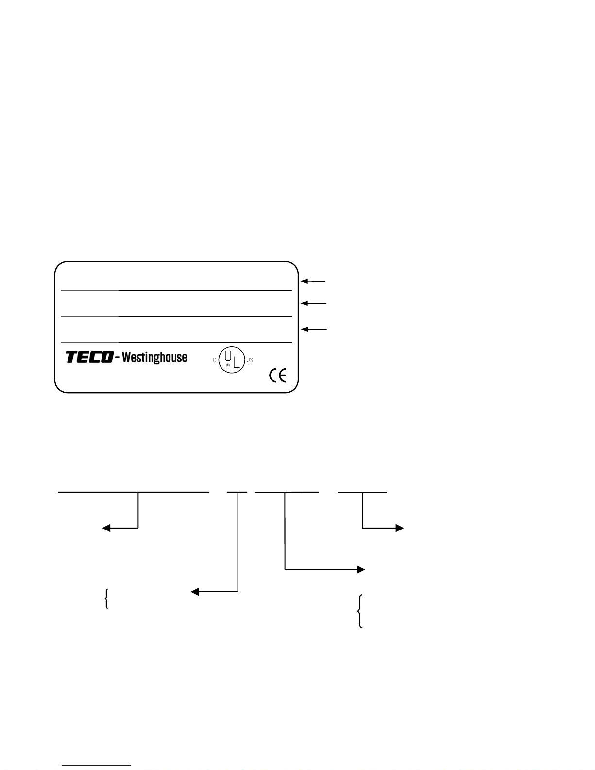
■ Inverter nameplate:
Model:MA7200-2002-N1 HP:2 KVA:2.7
AC Input: 1PH/3PH 200-230V 50/60Hz
AC Output: 3PH 0-230V Amps: 6.4A
LISTED
MOTOR COMPANY
(IND. CONT. EQ.)
848F
INVERTER MODEL
INPUT SPECIFICATION
OUTPUT SPECIFICATION
■ Inverter model number :
MA7200-2002-N1
MA7200
Series
N1: NEMA1
N4: NEMA4
Rated Voltage
2: 200~230V
4: 380~460V
Max. Applicable Motor
Capacity (HP)
0001 : 1HP
∫ ∫
0075 : 75HP
NEMA4 for 1~20HP only
1-1
Page 6
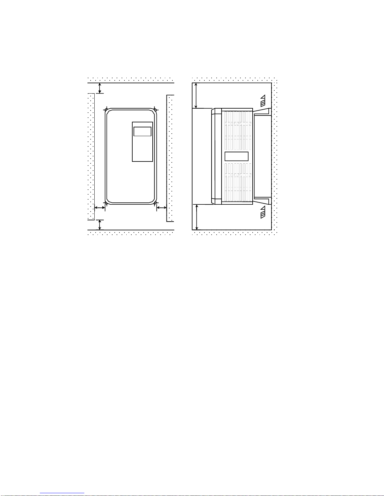
1.2 Installation
When installing the inverter, always provide the following space to allow normal
heat dissipation.
50 mm min.
120 mm
min.
AIR
ambient
temperature
-10 ~ + 40 ℃
50 mm
min.
30 mm
min.
30 mm
min.
120 mm
min.
(a) Space in Side (b) Space in Top/bottom
Fig. 1-a. Air clearance for MA7200 wall mounting
AIR
1-2
Page 7
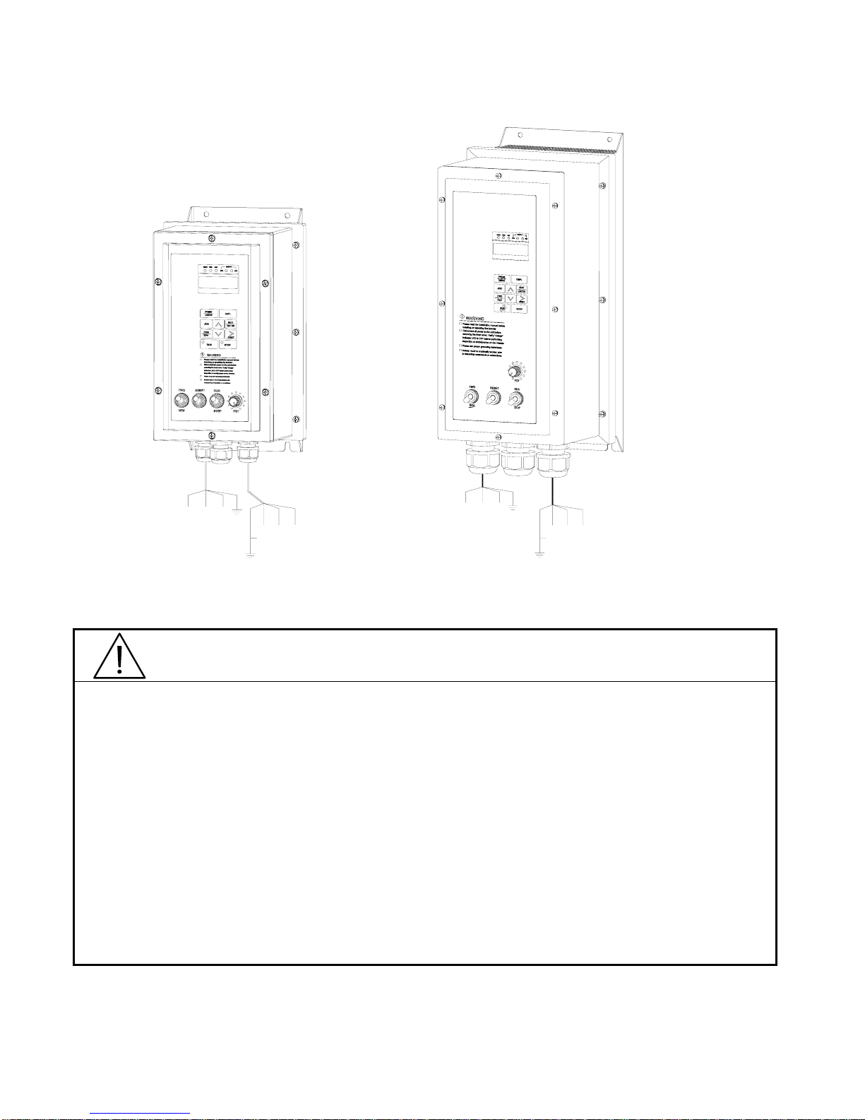
L3
L2(N)
220-240V
380-480V
L3
L1(L)
Single/ThreePhases
T1
3Phases IM
T3T2
L2(N)L1(L)
220-240V
380-480V
Single/ThreePhases
T1 T2 T3
3Phases IM
(a) NEMA4 Frame1 (b) NEMA4 Frame2
Fig. 1-b. MA7200 NEMA4 Installation
CAUTION
Location of equipment is important to achieve proper performance and normal
operating life. The MA7200 inverter should be installed in area where the following
conditions exist.
y Ambient temperature: +14 to 104
y Install the MA7200 in a location protected from rain, moisture and direct sunlight.
y Install the MA7200 in a location free from harmful mists, gases, liquids, airborne
dusts and metallic particles.
y Install the MA7200 in a location free from vibration and electromagnetic noise. (i.e.
welding machines, power units, etc…)
o
F, (-10 to 40oC).
y When mounting multiple units in a common enclosure, install a cooling fan or some
other means to cool the air entering the inverter to at least 113
1-3
o
F (+45oC) or below.
Page 8
1.3 Removing/Attaching the Digital Operator and Front cover
pp
CAUTION
Please disassemble Front Cover before you connect wires to terminals on MA7200
models.
• 230V 1~25HP & 460V 1~30HP models: Plastic instructions, so please disconnect
LCD Digital Operator before you disassemble Front Cover. After you finished the
wiring connection, assemble Front Cover first then reinstall LCD Digital Operator.
• 230V 30HP、40HP & 460V 40~75HP: Iron instructions, you can disassemble Front
Cover for wiring connection without disconnect LCD Digital Operator. Then
reinstall Front Cover back after you finished wiring connection.
MA7200 disassembly / Assembly procedures will be depended on different model as
follows:
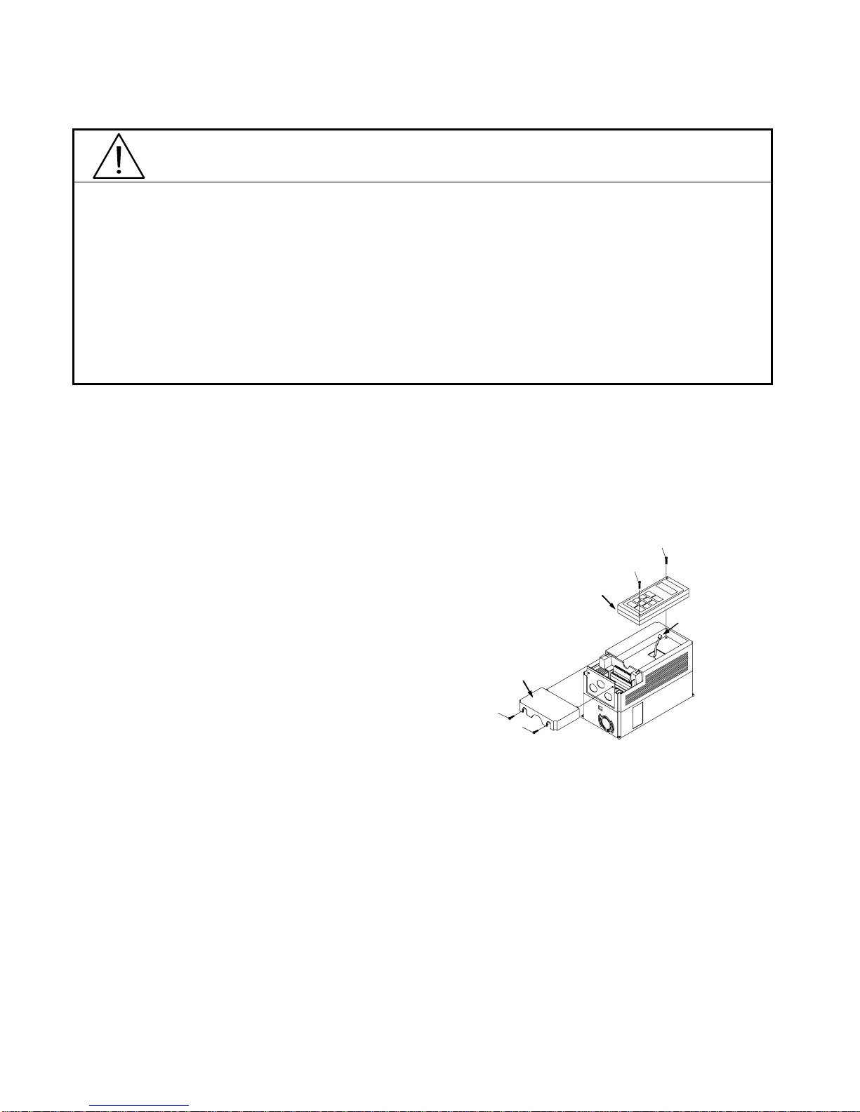
(A) For 230V : 1-2HP, 460V : 1-2HP
y MA7200-2001-N1 y MA7200-4001-N1
y MA7200-2002-N1 y MA7200-4002-N1
■ Removing the digital operator :
Take off the two screws on the front cover in the
place a and b. Remove the front cover and take
off the screws in the place c and d. Disconnect
the RS-232 cable connector on the backside of
LCD Digital
Operator
d
c
RS-232
Cable
Connector
the LCD digital operator. Lift and remove digital
operator.
■ Attaching the front cover and digital operator:
Connect the RS-232 cable connector on the back
Front Cover
a
b
of the LCD digital operator.
Attach the digital operator and tighten the screws in the place c and d. Insert the tabs of
the u
er part of front cover into the groove of the inverter and tighten the screws in the
place a and b.
1-4
Page 9
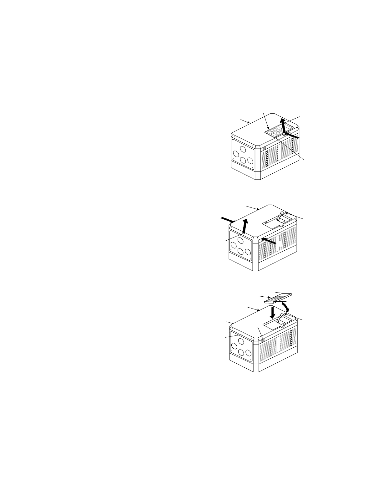
(B) For 230V : 3-10HP, 460V : 3-10HP
g
r
b
g
y MA7200-2003-N1 y MA7200-4003-N1
y MA7200-2005-N1 y MA7200-4005-N1
y MA7200-2007-N1 y MA7200-4007-N1
y MA7200-2010-N1 y MA7200-4010-N1
Removing the digital operator
■
Take off the screws in the place a. and b.
Press the lever on the side of the di
ital operato
in the direction of arrow 1 to unlock the digital
operator.
Disconnect the RS-232 cable connector on the
ack side of the LCD digital operator. Lift the
di
ital operator in the direction of arrow 2 to
remove the digital operator.
■ Removing the front cover
Press the left and right sides of the front cover in
the directions of arrow 1 and lift the bottom of the
cover in the direction of arrow 2 to remove the
front cover.
■ Mounting the front cover and digital operator
Insert the tab of the upper part of front cover into
the groove of the inverter and press the lower part
of the front cover onto the inverter until the front
cover snaps shut.
Connecting the RS-232 cable connector on the
back side of the LCD digital operator and hook
the digital operator at a on the front cover in the
direction of arrow 1.
Front Cover
Front
Cover
1
c
Operator
Front
Cover
e
c
LCD Digital Operator
2
2
1
Digital
a
1
d
b
2
a
1
b
RS-232
Cable
Connector
RS-232
Cable
Connector
Press the digital operator in the direction of arrow
2 until it snaps in the place b and then tighten the
screws in the place c and d. (on the front cover)
1-5
Page 10
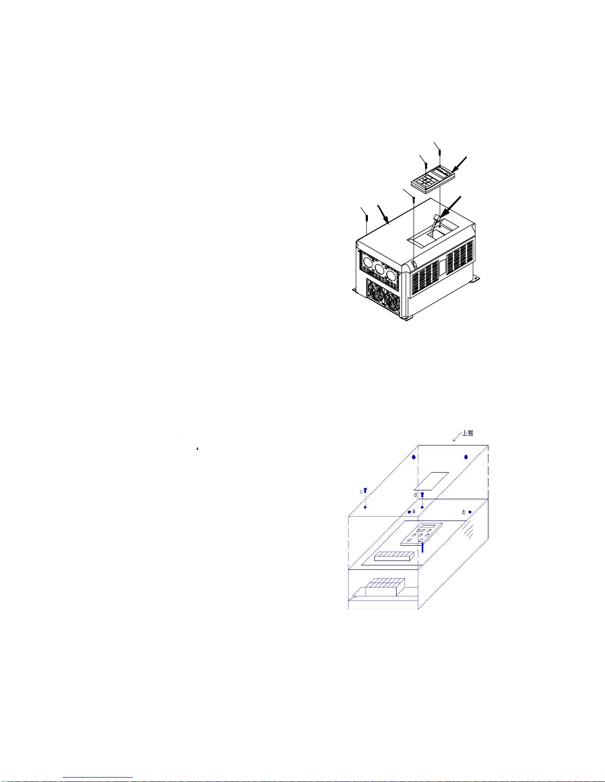
(C) For 230V 15,20HP and 460V 15,20HP Series
y MA7200-2015-N1 y MA7200-4015-N1
y MA7200-2020-N1 y MA7200-4020-N1
■ Removing the digital operator :
Take off the screws in the place a. and b.
Disconnect the RS-232 cable connector on the
back side of the LCD digital operator and then lift
the digital operator upwards.
■ Removing the front cover :
Loosen the two screws of the front cover in the
place c and d. And lift the bottom of the front
cover to remove the front cover.
■ Mounting the front cover and digital operator :
Insert the tab of the upper part of front cover into
the groove of the inverter and tighten the screws
in the place c and d.
Connect the RS-232 cable connector on the back
of the LCD digital operator.
Attach the digital operator and tighten the screws
in the place a and b.
a
LCD Digital
b
Front
Cover
d
c
Operator
RS-232 Cable
Connector
(D) For 230V 30~40HP and 460V 40~75HP Series
■ Removing the front cover: Loosen the two screws
of the front cover in the place a. and b. Then
loosen the two screws c and d
upwards. (Don’t removing the digital operator.)
■ Mounting the front cover: Press the front cover
and then tighten the screws in the place a, b, c and
d.
Front cover
, lift the front cover
1-6
Page 11
1.4 Wiring between Inverter and Peripheral devices and notice
CAUTION
1. After turning OFF the main circuit power supply, do not touch the circuit
components or change any circuit components before the “CHARGE” lamps
extinguished. (It indicates that there is still some charge in the capacitor).
2. Never do wiring work or take apart the connectors in the inverter while the power
is still on.
3. Never connect the inverter output U/T1, V/T2, W/T3 to the AC source.
4. Always connect the ground lead E to ground.
5. Never apply high voltage test directly to the components within the inverter. (The
semiconductor devices are vulnerable to high voltage shock.)
6. The CMOS IC on the control board is vulnerable to ESD. Do not try to touch the
control board.
7. If Sn-03 is 7,9,11 (2-wire mode) or is 8, 10, 12 (3-wire mode), except parameter
settings of Sn-01 and Sn-02, the other parameter settings will return to their initial
settings at factory. If the inverter is initially operated in 3-wire mode (Sn-03= 8,
10, 12), the motor will rotate in CCW sense after setting changed to 2-wire mode.
(Sn-03= 7, 9, 11). Be sure that the terminals 1 and 2 are OPEN so as not to
harmful to personal or cause any potential damage to machines.
CAUTION
1. Determine the wire size for the main circuit so that the line voltage drop is within
2% of the rated voltage. If there is the possibility of excessive voltage drop due to
wire length, use a larger wire (larger diameter) suitable to the required length
-3
10current(A)length(m) wire/km)(resistance wire3drop(V) voltageLine ×××Ω×=
2. If the length of the cable wire between the inverter and the motor exceeds 30m,
use a lower carrier frequency for PWM (adjust the parameter Cn-34). Refer to
Page 3-21
1-7
Page 12

Example of connection between the MA7200 and typical peripheral devices are shown as below.
f
r
r
r
A
r
r
r
Power supply
MCCB (Molded-Case Circuit Breaker)
y Choose the Molded Case Circuit Breaker (MCCB) o
proper current rating. Please refer to the selection guide
Power supply
switch(NFB)
and earth
leakage
breake
“1.10 Peripheral Units” on Page 1-22.
y Do not use a circuit breaker for start/stop operation.
y When a ground fault interrupter is used, select the one with
no influence for high frequency. Setting current should be
200mA or above and the operating time at 0.1 second or
longer to avoid false triggering.
Electromagnetic
contacto
C reacto
Input noise
filte
MA 7200
inverte
Zero phase
core
MC (Magnetic Contactor)
y It is not always necessary to have a Magnetic Contactor on
the input side. However, an input Magnetic Contactor can
be used to prevent an automatic restart after recovery from
an external power loss during remote control operation.
y Do not use the Magnetic Contactor for start/stop operation.
AC Reactor
y To improve power factor or to reduce surge current, install
an AC Reactor on the input side of the MA7200.
Input Noise Filter
y When used with TECO specified Input Noise Filter, the
MA7200 will comply with EN55011 class A regulation.
y Please refer to the selection guide “1.10 Peripheral Units”
on page 1-22.
MA7200 Inverter
y The input power supply can be connected to any terminal
R/L1, S/L2, T/L3 on the terminal block.
y Please connect the ground terminal E to the site ground
securely.
Output Noise Filter (Zero Phase Core)
y Install an Output Noise Filter between the MA7200 and the
Induction Motor to eliminate noise transmitted between the
power line and the inverter.
y Please refer to the selection guide “1.10 Peripheral
Devices” on page 1-22.
Induction
moto
Induction Motor
y When multiple motors are driven in parallel with an
inverter, the inverter rated current should be at least 1.1
times the total motor rated current.
y The inverter and the motor must be separately grounded.
1-8
Page 13
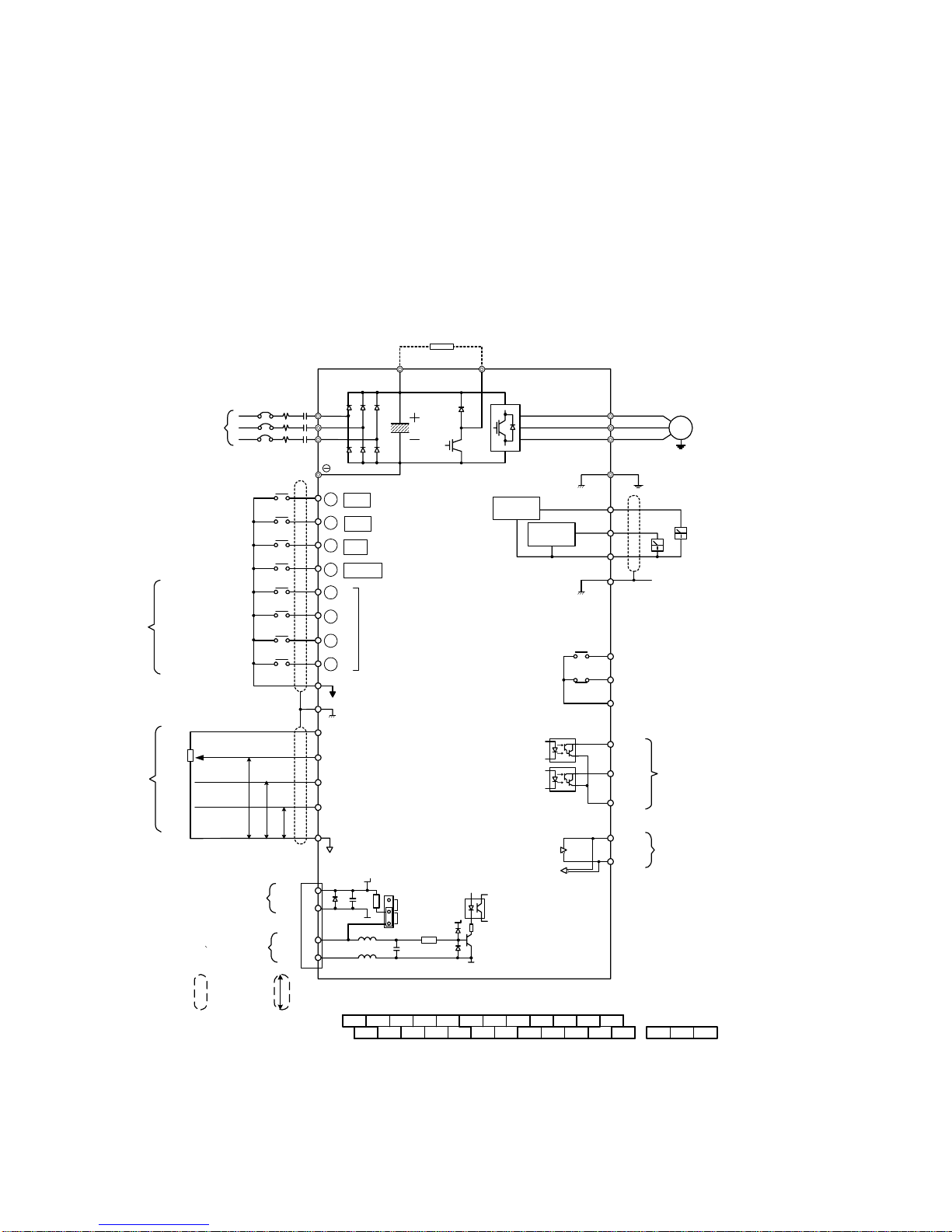
■ Standard Connection Diagram
The standard connection diagram of MA7200 is shown in Fig. 2. The sign ◎
indicates the main circuit terminal and the sign ○ indicates control circuit terminal. The
terminal function and arrangement are summarized in Table 1 and Table 2. There are
three types of control board, the terminal arrangement is shown as below.
(A) For Compact Size Type 230V : 1-2HP, 460V : 1-2HP (NEMA4 are the same)
•MA7200-2001/2-N1 •MA7200-4001/2-N1
Braking Resistor
B1/P B2
MC
Main Ckt
Power Supply
NFB
R/L1
S/L2
T/L3
U/T1
V/T2
W/T3
IM
FWD/ST OP
REV/STOP
External Fault
Fault RESET
Multi- Step
Speed Ref.1
Multi-Step
Speed R ed.2
Jogging
Fact ory Pres et
Acc. & Dec.
Switch
2k
1/2W
COMMAND
EXTERNAL FREQUENCY
(*4)Pulse Input Frequency Command
0 ~ +10V
Ω
4 ~ 20 mA
0 ~ +10V
0V
EXTERNAL PG
DC VOLTAGE
PG INPUT
(A PHASE)
P
P
IP12
IG12
A(+)
A(-)
1
2
3
4
5
6
7
8
SC (DG)
E
+12V Power Supply for
Speed Ref.
VIN Master Speed Ref.
AIN Master Speed Ref.
AUX Multi-Funtion
Analog Input
P
(*1)
CN2
GND Analog s ignal C ommon
(*4)
1
2
3
4
("Close":FWD)
FWD
REV ("Close":REV)
Eb
RESET
Multi-Function
Contact Input
Digital signal Common
Shield Sheath
TP1
OPEN
PULL UP
Output 1
(+12V, 20 mA)
0 ~ 10V, (20k
4 ~ 20 mA, (250
0 ~ 10V, (20k
IP12
Analog
Ω
)
Ω
Ω
)
)
Analog
Output 2
E
AO1
AO2
GND
RA
RB
RC
DO1
DO2
DOG
Grounding Lead
(<100
Multi-Function Contact Output
250V AC, <1A
30V DC, <1A
S(+)
S(-)
Ω
)
Analog Monitor 1, 2
(DC 0 ~ 10 V)
Multi-Function Output 1, 2
(Open Collector 48V, 50mA)
RS-485 Port
(*1)
Shield
Wire
Shielded
P
Twisted Wire
(*2) The terminal arrangement
(*3) The control board code No. : 4P101C0040001
(*4) The CN2 wire code No. : 4H339D0250001
Fig. 2-a Standard connection diagram
SC
13
E
24
VIN AIN AUX DO1 DO2 DOG
57
68
+12V
GND AO1 AO2
1-9
GND
S(-)
ES(+)
RA RB RC
Page 14
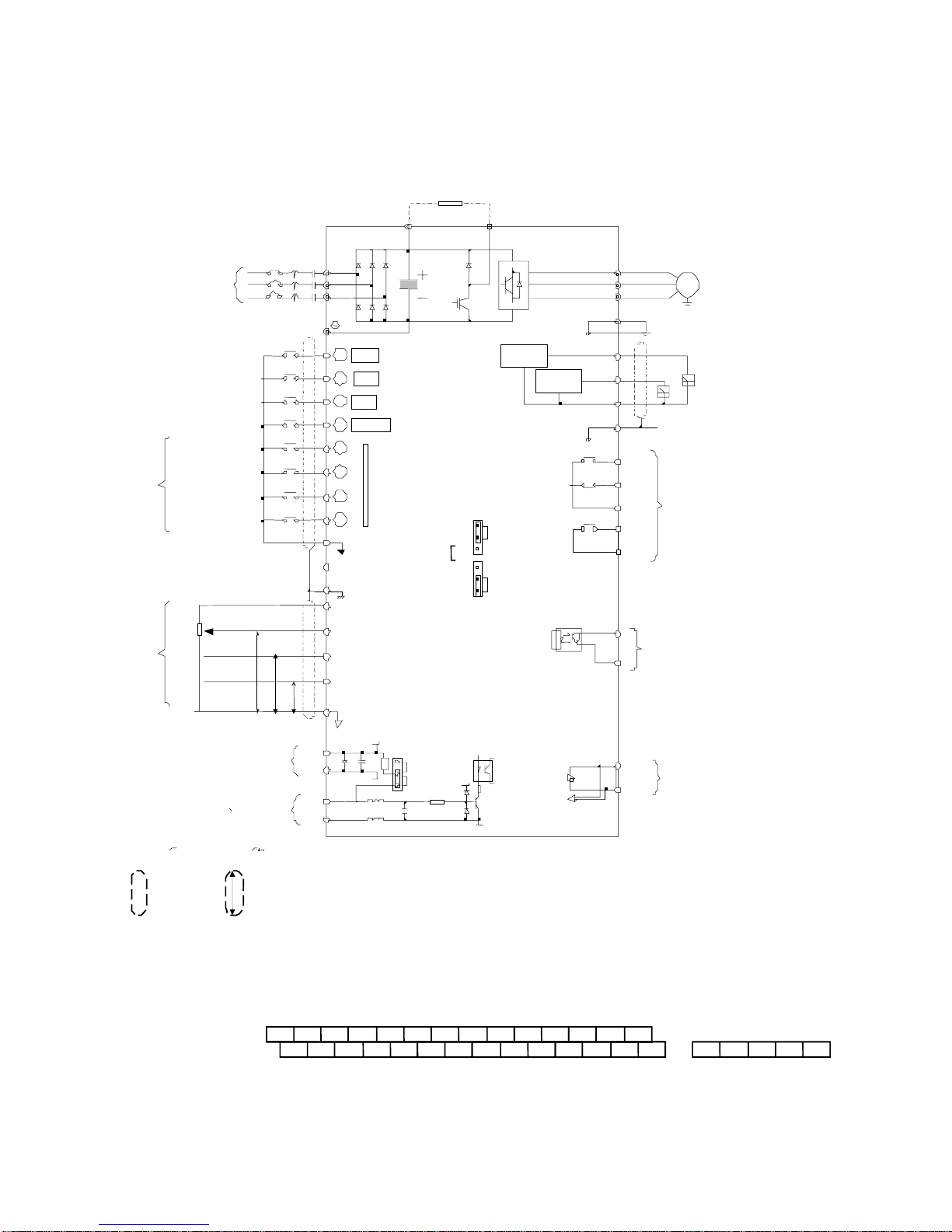
(B) 230V : 3-40HP, 460V : 3-75HP (NEMA4 to 20HP)
Ω
(
)
(*2)
yp
(
KΩ)
y MA7200-2003-N1 y MA7200-4003-N1
through through
MA7200-2040-N1 MA7200-4075-N1
Braking Resistor
B1/P B2
Main Ckt
Power Supply
FW D/STOP
REV/STOP
External Fault
Fault RESET
Multi-Step
Speed Ref.1
Factory Preset
Multi-Step
Speed Red.2
Jogging
Acc. & Dec.
Switch
2k
1/2W
COMMAND
EXTERNAL FREQUENCY
(*4)Pulse Input Frequency Command
Ω
4 ~ 20 mA
0 ~ +10V
EXTERNAL PG
DC VOLTAGE
PG INPUT
(A PHASE)
-10V ~ +10V
P
0V
P
MC NFB
R/L1
S/L2
T/L3
FW D ("Close":FWD)
1
2
REV ("Close":REV)
3
Eb
4
RESET
5
6
7
8
E
+12V or -12V Power Supply
Speed Ref.
for
VIN Master Speed Ref. 0 ~ 10V & -10V~10V
AIN Master Speed Ref.
AUX Multi-Function
Analog Input
P
(*1)
IP12
IG12
A(+)
A(-)
Multi-Function
Contact Input
24VG
(Sink Common)
24V
(Source Common)
Shield Sheath
SINK
20
GND Analog signal Common
TP1
OPEN
PULL UP
Analog
Output 1
TP2
TP2 :
TP2 :
, (20kΩ)
4 ~ 20 mA, (250Ω)
0 ~ 10V, (20k
IP12
(* 2)
SOURCE
SINK
(±12V, 20 mA)
U/T1
V/T2
W/T3
E
AO1
Analog
Output 2
)
AO2
GND
R1A
R1B
R1C
R2A
R2C
DO1
DOG
S(+)
S(-)
IM
Grounding Lead
(<100 Ω )
Analog Monitor 1, 2
(DC 0 ~ 10 V)
Multi-Function Contact Output
250V AC, <1A
30V DC, <1A
Multi-Function Output 1
Open Collector 48V, 50mA
RS-485 Port
(*1)
( * 1)
input, the short jumper of TP2 must be set to SINK position, and set to SOURCE position for source type input.
( * 2) The term inal
(*3) The terminal arrangement
must be set to SIN K posit
VIN Ref. can be set in two input methods as 0~10V or -10~+ 10V
(
*3)
(*4) The control board code No. : 4P101C 0060002
( * 4)
The term inal A(+), A (-) can be the output term inal of Pulse Input Frequency Command, and the jum per of TP1 must be set to OPEN position.
Shield
Wire
1
and
8
P
j
The terminal can be set as SINK or SOURCE type input interf ace, when setting as sink t
Shield Wire
c
Shielded
P
Twisted W ire
~
Shield e Tw isted
can be set
as SINK or
ion, and set to SOURCE position fo r source type input.
Pulse Input Frequency Command: 0~32K H z, 3~12V High torsion, input re sistor 2.7K Ω
1 3 5
( * 5) The term inal arrangem ent
( * 6) The contro l board code No. : 4P101C 0130001
24VG
Fig. 2-b Standard connection diagram
E
2
Fig. 2-b Standard connection diagram
1 8
S(+)
A(
-)
S(-)
~
R2A R2C R1A R1B R1C
Wire
S OURCE
24VG
1 3 5 7 AUXVIN AIN24V DO1 DOG IP12 A(+) A(-)
E
2 4 6 8 +12VGND AO1 AO2 E IG12 S(+) S(-)GND R2A R2C R1A R1B R1C
4
type input interface, when setting
7 VIN AIN
24V DOG
6 8
+12V-12V
GND
AUX DO1
AO1 AO2 E
as sink type input, the sho rt jum per of TP2
~
c
j
A(+)
IP12
IG12
1-10
e
Page 15
1.5 Description of terminal function
/
/
/
Table 1 Main circuit terminals
Terminal 230V:1~20HP, 460V:1~20HP 230V:25~40HP, 460V:25~75HP
R/L1
S/L2
T/L3
B1/P
B2
Θ
⊕
B2/R
U/T1
V/T2
W/T3
E
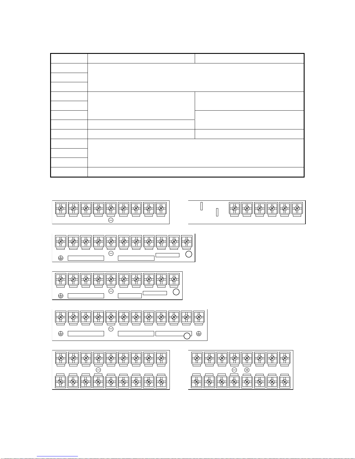
■ Terminal block configuration
․230V : 1 ~ 2HP ․ 460V : 1 ~ 2HP
L1 S/L2 T/L3
R/
Main circuit input power supply
(For single phase power supply, please use R/L1, S/L2 as input terminal)
B1/P, B2: External braking resistor
B1/P, Θ: DC power supply input
• ⊕ - \ : DC power supply or
-
braking unit
Unused -
Inverter output
Grounding lead (3rd type grounding)
J4
B1/P
B2
T1 V/T2
U/
W
T3
B1/P
-
J2
B2
R/L1S/
L2 T/L3
T1 V/T2
U/
W
T3
․230V : 3~5HP
U
R
/L1
S
/L2
T
E
Power In
/L3
B1/P B1/R B2
Dynamic Brake
/T1V/T2
To M ot or
CHARGE
W
/T3
․460V : 3~5HP
U
R
/L1
S
/L2
T
E
Power In
/L3
B1/P B2
Dynamic Brake
/T1V/T2
To M ot or
CHARGE
W
/T3
․230V/460V : 7.5~10HP
R
/L1
S
/L2
T
E
Power In
/L3
B1/P B1/R B2
Dynamic Brake
U
/T1V/T2W/T3
To Motor
CHARGE
E
․230V/460V : 15~20HP ․ 230V : 25~40HP, 460V : 25~75HP
R/L1
S/
L2
L3
T/
U/
V/
W
T2
T3B1/P B2
T1
R/L1 S/L2 T/L3 U/T1
W
V/
T2
/T3
1-11
Page 16
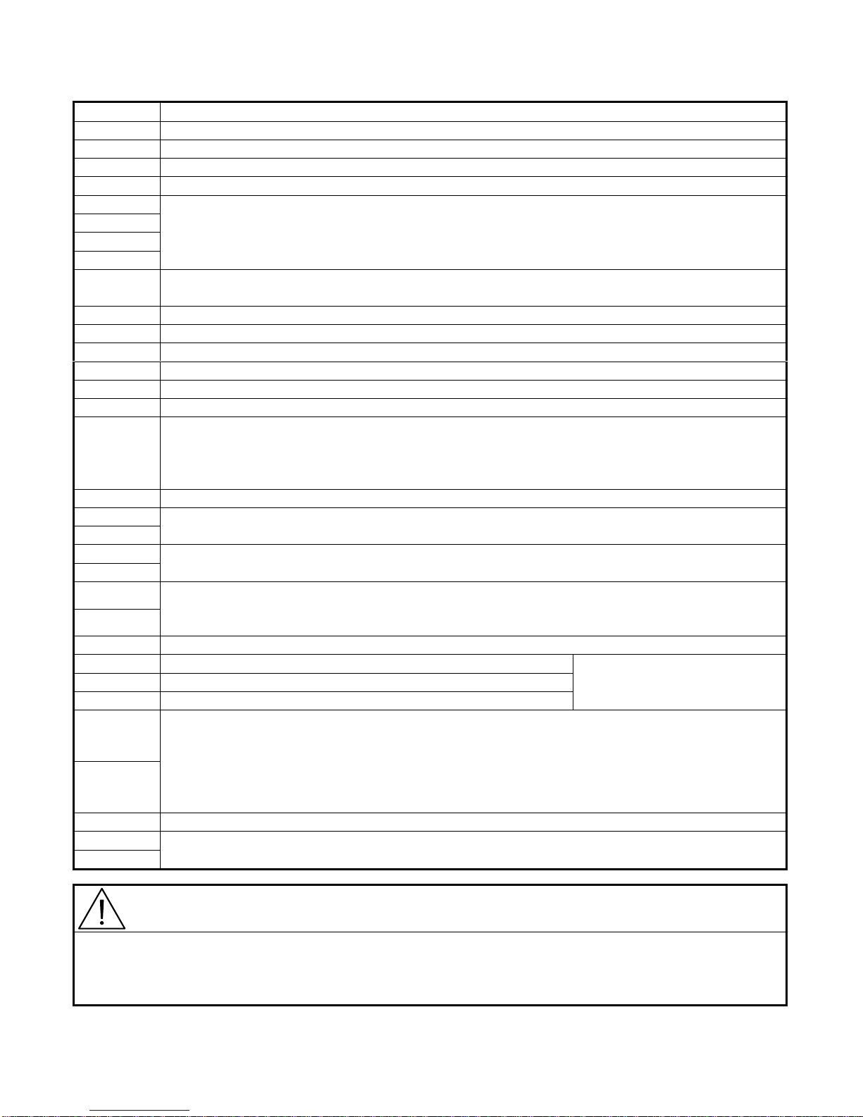
Table 2 Control circuit terminals
Terminal Functions
1(DI1) Forward Operation – Stop Signal
2(DI2) Reverse Operation – Stop Signal
3(DI3) External Fault Input
4(DI4) Fault Reset
5(DI5)
6(DI6)
7(DI7)
8(DI8)
SC(DG)
(24VG)
24V Source Common Point (Locate the short jumper of TP2 in SOURCE position)
E Connection to Shield Signal Lead (Frame Ground)
+15V(+12V) DC voltage for External Device
-12V Only support by the board 4P101C01301
VIN Master speed Voltage Reference (0~10V) (4P101C01301 support –10V~10V input)
AIN Master speed Current Reference (4~20mA)
AUX
GND Analog Signal Common
IP12
IG12
A(+)
A(-)
AO1
AO2
GND Common Lead for Analog Port
RA(R1A) Relay Contact Output A
RB(R1B) Relay Contact Output B
RC(R1C) Relay Contact Common
Multifunction Input Terminal: 3-Wire Operation, Load/Remote Control, Multi-Speed Select,
FWD/REV Select, ACC/DEC Choice, ACC/DEC Halting, Base Block, Overheat Warn, PID
Control, DC Braking, Speed Search, Up/Down Function, PG Feedback Control, External Fault,
Timer function, Multifunction Analog Input Setting
Digital Signal Ground
Sink Common Point (Locate the short jumper of TP2 in SINK position)
Auxiliary Analog Input:
Auxiliary frequency Command, Frequency Gain, Frequency Bias, Overtorque Detection, Output
Voltage Bias, ACC/DEC Ramp, DC-Brake Current, Stall Prevention Current Level during
Running Mode, PID Control, Lower-Bound of Frequency Command, Frequency-Jump-4, etc
External Power Source For PG Feedback Use
Signal Input of PG (also can be the input terminal of Pulse Input Frequency Command)
Analog Multifunction Output Port:
Frequency Commend, Output Frequency, Output Current, Output Voltage, DC Voltage, PID
Controlled Value, Analog Command Input of VIN, AIN or AUX.(Below 2mA)
Same function as terminal DO1,
DO2
DO1
DO2
R2A
R2B
DOG Common Terminal (of Open Collector Transistor)
S(+)
S(-)
Digital Multi-Function (Open Collector) Output “1”, “2” Terminals:
During-Running, Zero-speed, Agreed-frequency, Agree-frequency-setting, Frequency-Output,
Inverter-Operation-Ready, Undervoltage-Detection, Base-Block Output, Run Source, Frequency
command, Overtorque Detection, Frequency Command Invalid, Fault, Undervoltage, Overheat,
Motor Overload, Inverter Overload, During-Retry, Communication-Fault, Timer-Function-Output
RS-485 Port
Caution
• Use the control circuit terminals VIN, AIN according the setting of Sn-24.
• The MAX. Output current at terminal (+15V or +12V) is 20mA.
• The multi-function analog output terminals AO1, AO2 is a dedicated output for a frequency meter, ammeter,
etc. Do not use these 2 analog outputs for feedback control or any other control purpose.
1-12
Page 17
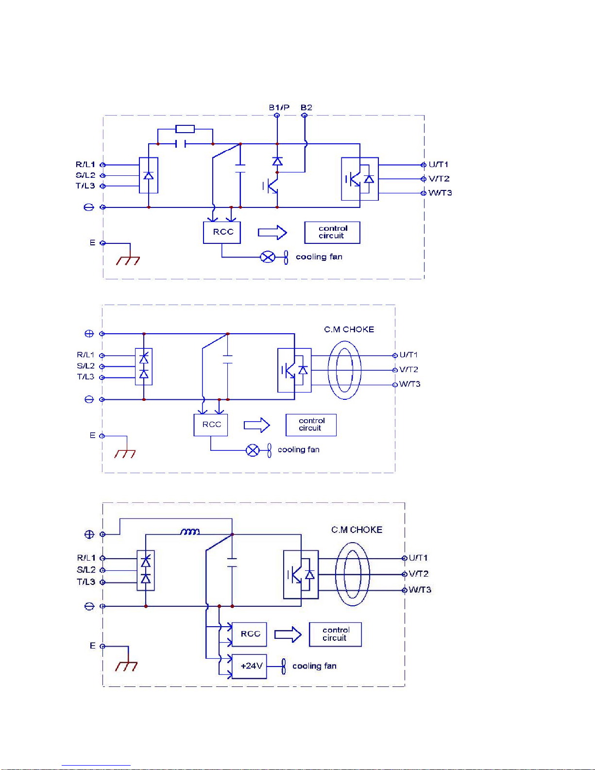
1.6 Main Circuit Wiring Diagram
Main Circuit Wiring Diagram of MA7200:
1. 230V/460V : 1~20HP
2. 230V : 25HP 460V : 25~30HP
3. 230V : 30~40HP 460V : 40~75HP
1-13
Page 18

1.7 Wiring main circuit and notice
■ Main circuit wiring
The non-fusible-breaker (NFB) should be installed between the AC source and the
R/L1-S/L2-T/L3 input terminal of MA7200 inverter. The user can make his own decision
of installing electromagnetic contactor block (MCB) or not. To protect against the false
triggering of leakage-current, the user should install a leakage current breaker with
amperage sensitivity≧200mA and operation time≧0.1 sec.
Table 3 230V and 460V class applicable wire size and connector
MA7200 model Wire size (mm2)
Power
supply
230V
1Φ
230V
3 Φ
460V
3Φ
/3Φ
Applicable
Power Rating
(HP)
1HP 2 4.8
2HP 2.7 6.4
3HP 4 9.6
5.4HP 7.5 17.5 5.5 5.5
7.5HP 10.1 24 8
10HP 13.7 32 8
15HP 20.6 48 14 8
20HP 27.4 64 22 8
25HP 34 80 22 14
30HP 41 96 38 14
40HP 54 130 60 22
1HP 2.2 2.6
2HP 3.4 4
3HP 4.1 4.8
5.4HP 7.5 8.7
7.5HP 10.3 12
10HP 12.3 15 5.5 5.5
15HP 20.6 24 8 8
20HP 27.4 32 8 8
25HP 34 40 8 8
30HP 41 48 14 8
40HP 54 64 22 8
50HP 68 80 22 14
60HP 82 96 38 14
75HP 110 128 60 22
Rated
*1
KVA
*1 : It is assumed constant torque load.
Rated
current
(A)
Main
circuit
2~5.5 2~5.5 0.5~2
2~5.5 3.5~5.5 0.5~2
3.5~5.5 3.5~5.5 0.5~2
2~5.5 2~5.5 0.5~2
2~5.5 3.5~5.5 0.5~2
2~5.5 3.5~5.5 0.5~2
2~5.5 3.5~5.5 0.5~2
3~5.5 3.5~5.5 0.5~2
Ground
connection
*2
wire E (G)
5.5~80.5~2
5.5~80.5~2
Control
*3
wire
0.5~2
0.5~2
0.5~2
0.5~2
0.5~2
0.5~2
0.5~2
0.5~2
0.5~2
0.5~2
0.5~2
0.5~2
0.5~2
0.5~2
0.5~2
*4
NFB
TO-50EC(15A) CN-11
TO-50EC(20A) CN-11
TO-50EC(20A) CN-11
TO-50EC(30A) CN-16
TO-100S(50A) CN-18
TO-100S(60A) CN-25
TO-100S(100A) CN-50
TO-100S(100A) CN-65
TO-225S(150A) CN-80
TO-225S(175A) CN-100
TO-225S(175A) CN-125
TO-50EC(15A) CN-11
TO-50EC(15A) CN-11
TO-50EC(15A) CN-11
TO-50EC(15A) CN-18
TO-50EC(20A) CN-18
TO-50EC(30A) CN-25
TO-50EC(30A) CN-25
TO-100S(50A) CN-35
TO-100S(75A) CN-50
TO-100S(100A) CN-50
TO-100S(100A) CN-65
TO-125S(125A) CN-80
TO-225S(175A) CN-100
TO-225S(175A) CN-125
MCB
*4
*2 : The main circuit has terminals of R/L1, S/L2, T/L3, U/T1, V/T2, W/T3, B1/P, B2/R, B2,Θ.
*3 : The control wire is the wire led to the pin terminals of control board.
*4 : In Table 3, the specified Part No. of NFB and MC are the item No. of the products of TECO. The
customer can use the same rating of similar products from other sources. To decrease the noise
interference, be sure to add R-C surge suppressor (R: 10Ω/5W, C: 0.1µF/1000VDC) at the 2
terminals of coils of electromagnetic contactor.
1-14
Page 19
■ External circuit wiring precaution:
(A) Control circuit wiring:
(1) Separate the control circuit wiring from main circuit wiring (R/L1, S/L2, T/L3, U/T1,
V/T2, W/T3) and other high-power lines to avoid noise interruption.
(2) Separate the wiring for control circuit terminals RA-RB-RC (R1A-R2B-R2C) (contact
output) from wiring for terminals
c~j
, A01, A02, GND, DO1, DO2 , DOG 15V(or
+12V, -12V), VIN, AIN, AUX, GND, IP12, IG12, A (+), A (-), S(+) and S(-).
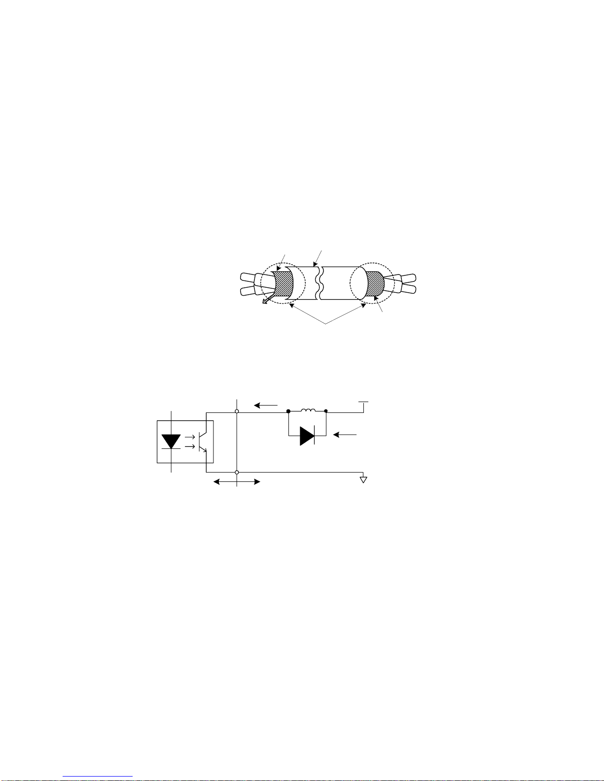
(3) Use the twisted-pair or shielded twisted-pair cables for control circuits to prevent
operating faults. Process the cable ends as shown in Fig. 3. The max. wiring distance
should not exceed 50 meter.
Shield sheath
Connect to shield
sheath terminal E
Insulated with tape
Armor
Do not
connect here
Fig. 3. Processing the ends of twisted-pair cables
When the digital multi-function output terminals connect serially to an external relay, an
anti-parallel freewheeling diode should be applied at both ends of relay, as shown below.
MA7200
7200MA
50 mA max.
external wiring circuit
48V max.
free-wheeling diode
(100V, >100mA)
Fig. 4. The Optical-couplers connect to external inductive load
(B) Wiring the main circuit terminals:
(1) Input power supply can be connected to any terminal R/L1, S/L2 or T/L3 on the
terminal block. The phase sequence of input power supply is irrelevant to the phase
sequence.
(2) Never connect the AC power source to the output terminals U/T1, V/T2 and. W/T3.
(3) Connect the output terminals U/T1, V/T2, W/T3 to motor lead wires U/T1, V/T2, and
W/T3, respectively.
(4) Check that the motor rotates forward with the forward run source. Switch over any 2
of the output terminals to each other and reconnect if the motor rotates in reverse with
the forward run source.
(5) Never connect a phase advancing capacitor or LC/RC noise filter to an output circuit.
1-15
Page 20
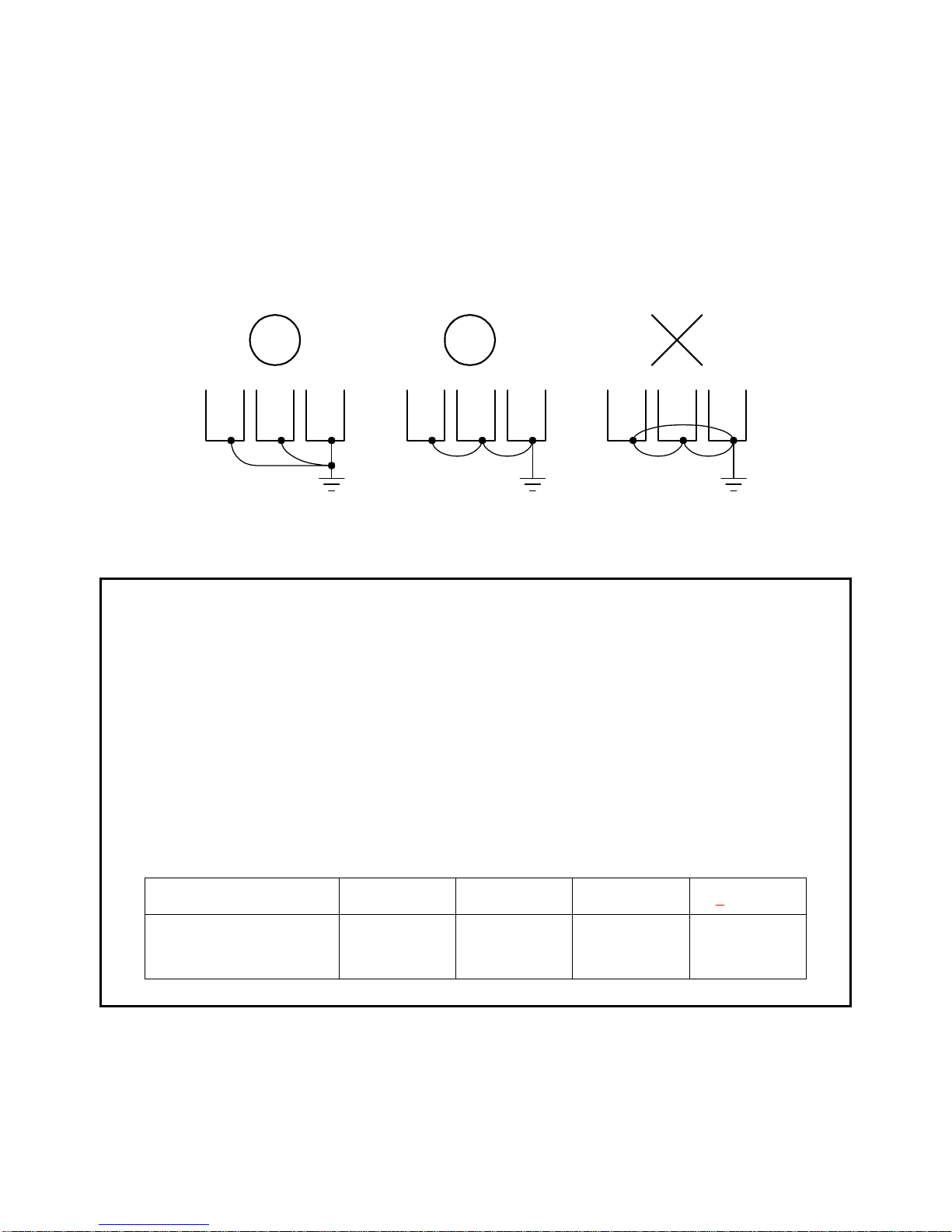
(C) GROUNDING :
(1) Always use the ground terminal (E) with a ground resistance of less than 100Ω.
(2) Do not share the ground wire with other devices, such as welding machines or
power tools.
(3) Always use a ground wire that complies with the technical standards on electrical
equipment and minimize the length of ground wire.
(4) When using more than one inverter, be careful not to loop the ground wire, as
shown below.
(a) OK (b) OK (c) NO
Fig. 5. MA7200 ground winding
• Determine the wire size for the main circuit so that the line voltage drop is within
2% of the rated voltage. (If there is the possibility of excessive voltage drop, use a
larger wire suitable to the required length)
• Installing an AC reactor
If the inverter is connected to a large-capacity power source (600kVA or more),
install an optional AC reactor on the input side of the inverter. This also improves
the power factor on the power supply side.
• If the cable between the inverter and the motor is long, the high-frequency
leakage current will increase, causing the inverter output current to increase as
well. This may affect peripheral devices. To prevent this, adjust the carrier
frequency, as shown below:
Cable length < 100ft. 100-165ft. 166-328ft.
Carrier frequency
(Cn-34)
15kHz max
(Cn-34=6)
10kHz max
(Cn-34=4)
5kHz max
(Cn-34=2)
>
329ft.
2.5kHz
(Cn-34=1)
1-16
Page 21
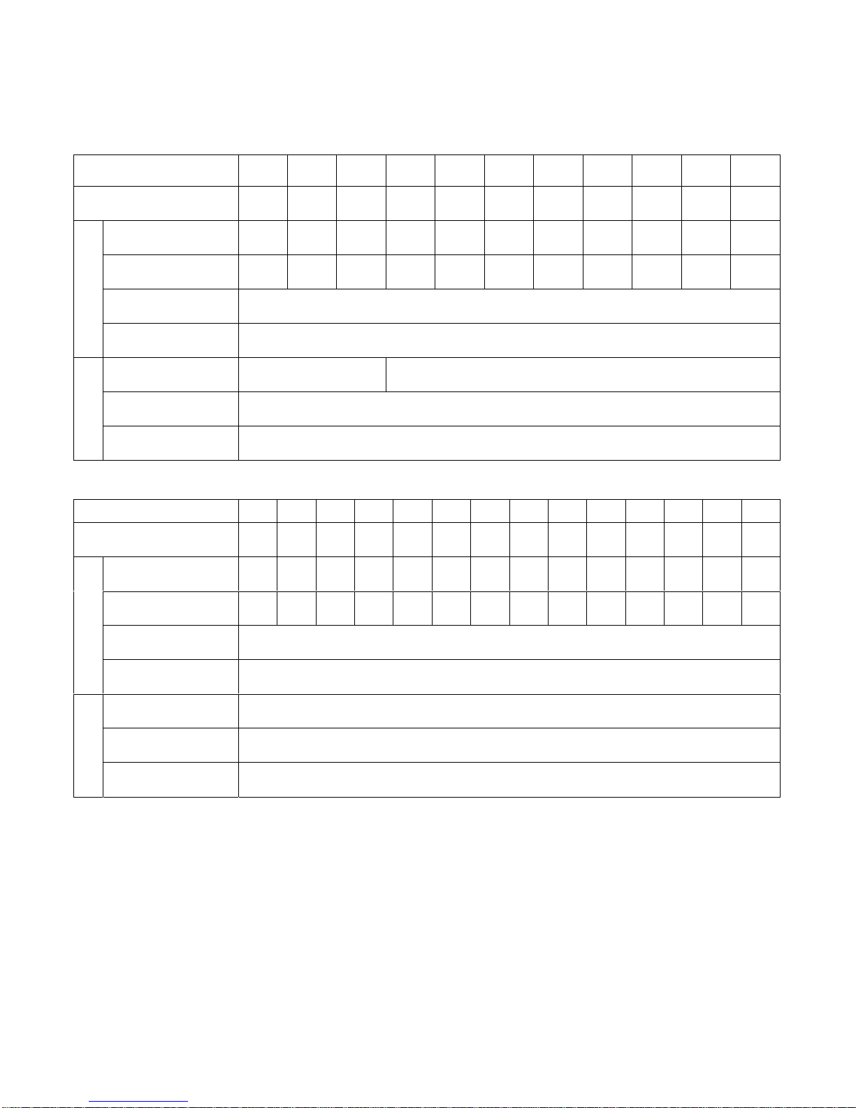
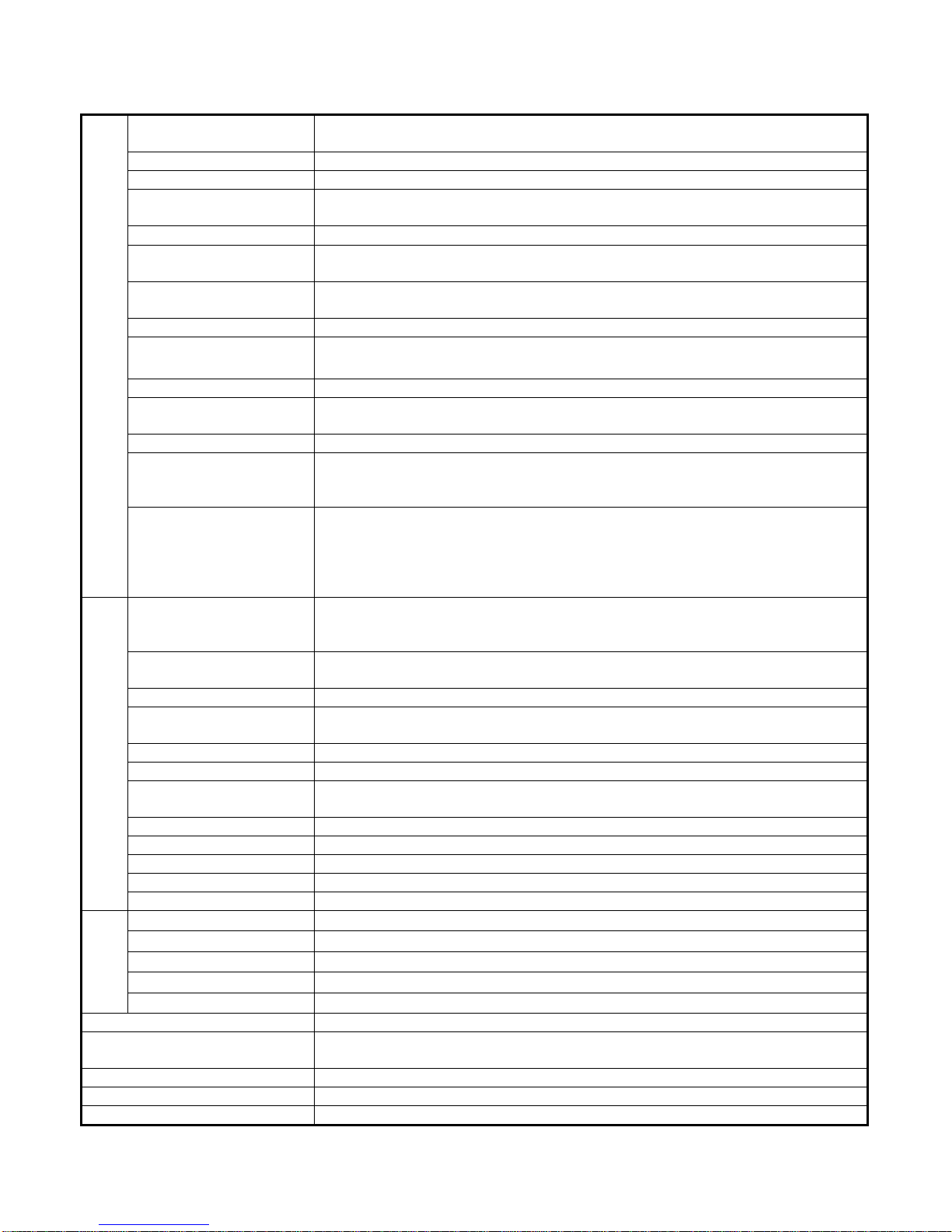
1.8 Inverter Specifications
Basic Specifications
(a) 230V Series
Inverter (HP) 12357.5101520253040
Max. Applicable Motor
Output HP
Capacity (KVA)
Max. Output Voltage
Output Characteristics
Frequency (Hz)
Allowable Voltage
Allowable Frequency
Power Supply
*1
(KW)
Rated Output
Rated Output
Current (A)
(V)
Max. Output
Rated Voltage,
Frequency
Fluctuation
Fluctuation
1
(0.75)2(1.5)3(2.2)
2 2.7 4 7.5 10.1 13.7 20.6 27.4 34 41 54
4.8 6.4 9.6 17.5 24 32 48 64 80 96 130
1PH/3PH 200V~230V,
50/60Hz
5.4
(4)
Through Parameter Setting 0.1~400.0 Hz
7.5
(5.5)10(7.5)15(11)20(15)25(18.5)30(22)40(30)
3-Phases, 200V~230V
3-Phases, 200V~230V, 50/60Hz
-15% ~ +10%
±5%
(b) 460V Series
Inverter (HP) 1 2 3 5 7.5101520253040506075
Max. Applicable Motor
Output HP
Capacity (KVA)
Max. Output Voltage
Output Characteristics
Frequency (Hz)
Allowable Voltage
Allowable Frequency
Power Supply
*1
(KW)
Rated Output
Rated Output
Current (A)
(V)
Max. Output
Rated Voltage,
Frequency
Fluctuation
Fluctuation
1
2
(1.5)3(2.2)
(0.75)
2.2 3.4 4.1 7.5 10.3 12.3 20.6 27.4 34 41 54 68 82 110
2.6 4 4.8 8.7 12 15 24 32 40 48 64 80 96 128
5.4
7.5
(4)
(5.5)10(7.5)15(11)20(15)
3-Phases, 380V~460V
Through Parameter Setting 0.1~400.0 Hz
3-Phases, 380V ~ 460V
-15% ~ +10%
±5%
25
(18.5)
, 50/60Hz
30
(22)40(30)50(37)60(45)75(55)
*1. Based on 4 pole motor
*2. The spec. of NEMA4 are the same
1-17
Page 22
General Specifications
Operation Mode
Control Mode Sinusoidal PWM
Frequency Control Range 0.1Hz ~ 400Hz
Frequency Accuracy
(varied with temperature)
Speed Control Accuracy
Frequency Command
Resolution
Frequency Output
Resolution
Overload Resistibility 150% Rated Current for 1 Min
Frequency Setting Signal
Acc./Dec. Time 0.0~6000.0 sec ( Accel/Decel Time Can Be Set Independently)
Voltage–Frequency
Characteristics
Control Characteristics
Regeneration Torque Approx. 20%
Basic Control Function
Extra Function
Stall Prevention
Instantaneous
Overcurrent
Motor Overload Protection Electronic Overload Curve Protection
Inverter Overload
Protection
Overvoltage Stop if VDC410V (230 Class) or VDC820V (460 Class)
Undervoltage Stop if VDC200V (230 Class) or VDC400V (460 Class)
Momentary Power Loss
Ride-Through time
Protection Function
Overheat Protection Protected by Thermistor
Grounding Protection Protection by DC Current Sensor
Charge Indication (LED) Lit when the DC Bus Voltage Above 50V
Input Phase Loss (IPL) Motor coasts to stop at Input Phase Loss
Output Phase Loss (OPL) Motor coasts to stop at Output Phase Loss
Application Site Indoor (No Corrosive Gas And Dust Present)
Ambient Temperature -10ºC ~ +40ºC (Not Frozen)
Storage Temperature -20ºC ~ +60ºC
Ambient Humidity Below 90%RH (Non-Condensing)
Condition
Environmental
Height, Vibration Below 1000M, 5.9m/S2 (0.6G), (JISC0911 Standard)
Communication Function RS-485 Installed (MODBUS Protocol)
Encoder Feedback Interface
EMI Meet EN 61800-3 With Specified EMI Filter
EMS Compatibility Meet EN 61800-3
Option PROFIBUS Card
Graphic LCD Panel (English and Chinese) with parameters copying (LED:
option)
Digital Command: ±0.01% (-10 ~ +40ºC),
Analog Command: ±0.1% (25ºC±10ºC),
±0.1%(V/F with PG feedback), ±0.5%(Sensorless Vector Control)
Digital Command: 0.01Hz Analog Command: 0.06Hz/60Hz
0.01Hz
DC 0~+10V / 4~20 mA, DC-10V~+10V and Pulse Input Frequency Command
(Above 230V/460V 3HP)
V/F Curve Can Be Set Through Parameter Setting
Restart After Momentary Power Loss, PID Control, Auto Torque Boost, Slip
Compensation, RS_485 Communication, Speed Feedback Control, Simple
PLC function, 2 Analog Output Port
Cumulative Power on & Operation Hour memory, Energy Saving, Up/Down
Operation, 4 Different sets of Fault Status Record (Including Latest one),
MODBUS Communication, Multiple-Pulse Output Ports, Select Local/Remote,
Customer Application Software Environment (C.A.S.E), SINK/SOURCE
Interface.
During Acceleration/Deceleration and constant Speed Running
(Current Level Can Be Selected During Acceleration and Constant Speed
Running. During Deceleration, Stall Prevention Can Be Enabled or Disabled)
Stopped if above 200% Rated Current
Stopped if above 150% Rated Current for 1 Min.
15ms, stop otherwise
Built-in PG Feedback Interface and set to Open-collector Interface Drive or
Complementary Interface Drive
1-18
Page 23
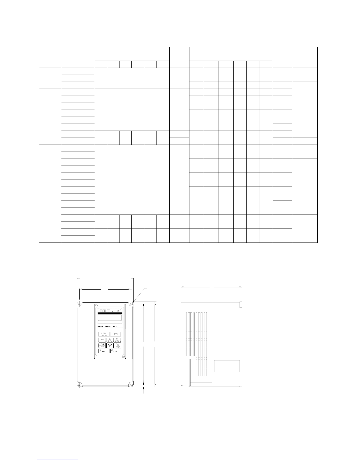
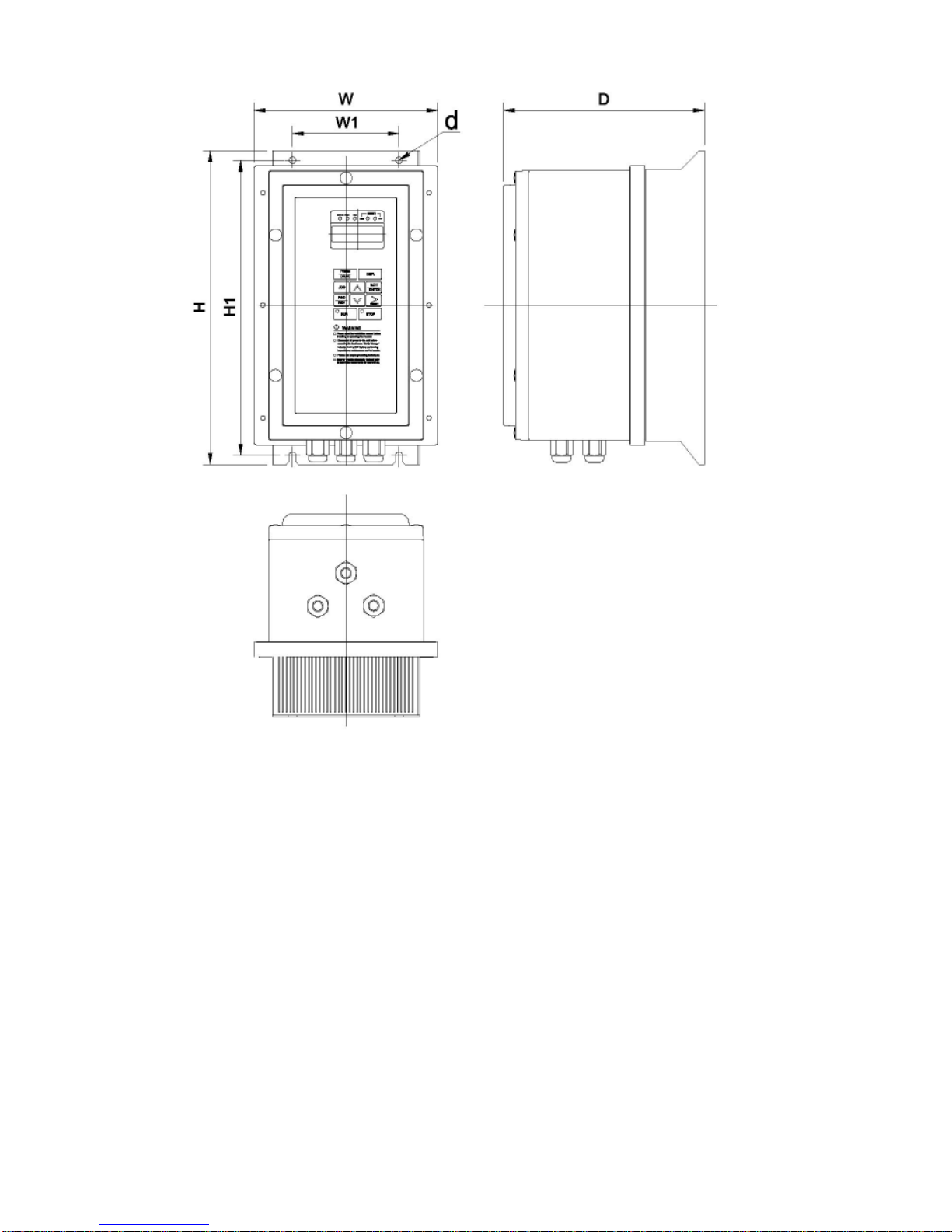
1.9 Dimensions
Voltage
230V
1/3Φ
230V
3Φ
460V
3Φ
Inverter
Capacity(HP)
1
2
3
5 140 279.5 176.5 126 226 M6 4.3
7.5
10
15
20
25
30 30 31
40
1
2
3
5
7.5
10
15
20
25
30
40
50
60
75
Open Chassis Type (IP00)
(mm)
WH DW1H1d
Weight
(kg)
Enclosed Type (NEMA1) (mm)
Weight
WHDW1H1d
132 217 143.5 122 207 M5 2.3 (a)
-
(kg)
140 279.5 176.5 126 226 M6 4.3
211.2 300 215 192 286 M6 5.7
-
265 360 225 245 340 M6
12
13
269 553 277 210 530 M10
269 647 277 210 530 M10
31
32 (c)
132 217 143.5 122 207 M5 2.3 (a)
140 279.5 176.5 126 226 M6 4.3
211.2 300 215 192 286 M6 5.7
-
12
265 360 225 245 340 M6
13
269 553 277 210 530 M10 30 269 647 277 210 530 M10 31
308 653 282 250 630 M10 46 308 747 282 250 630 M10 47
Reference
Figure
(b)
(b)
(c)
(a) 230V / 460V : 1~2HP
W1
W
d
H
H
1
H
2
D
1-19
Page 24
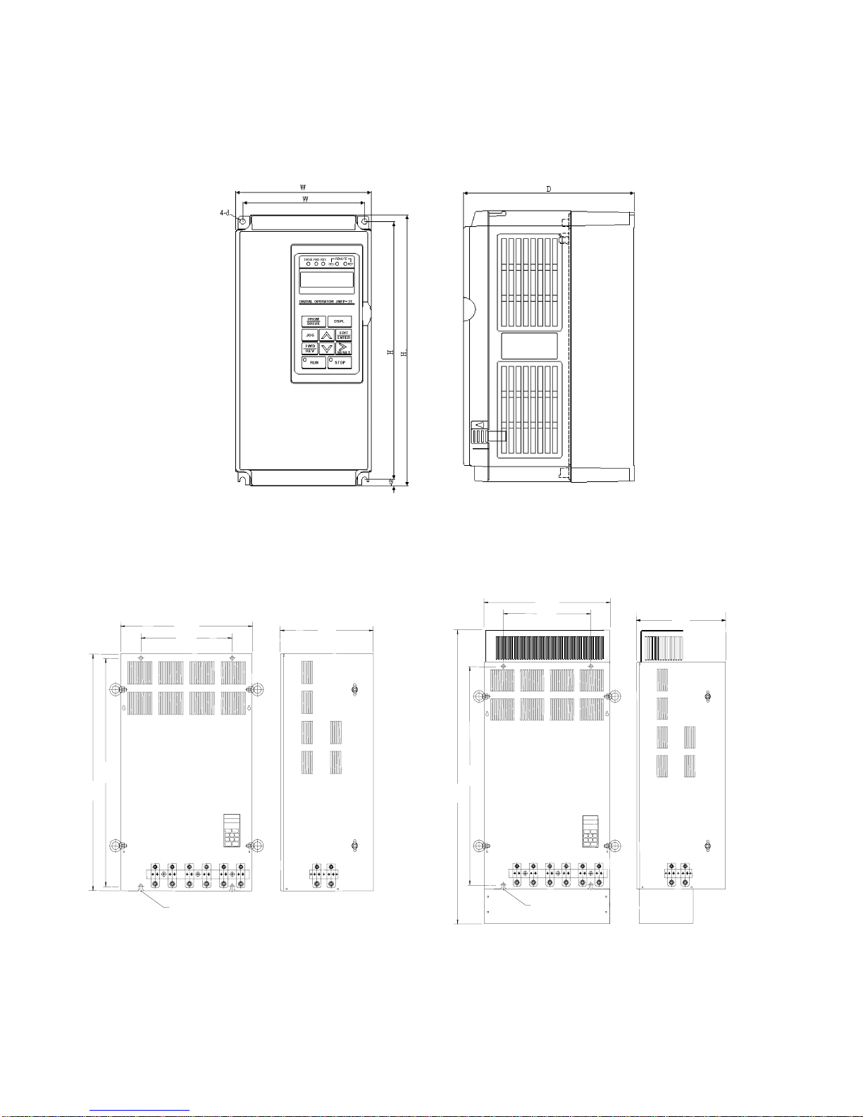
(b) 230V : 3HP~25HP
460V : 3HP~30HP
(c) 230V : 30HP~40HP
460V : 40HP~75HP
W
W1
1
1
W
W1
D
D
H1
H
(Open Chassis Type-IP00) (Enclosed, Wall-mounted Type-NEMA1)
d
(d) NEMA4 Type : 1HP~20HP
H1
H
d
1-20
Page 25
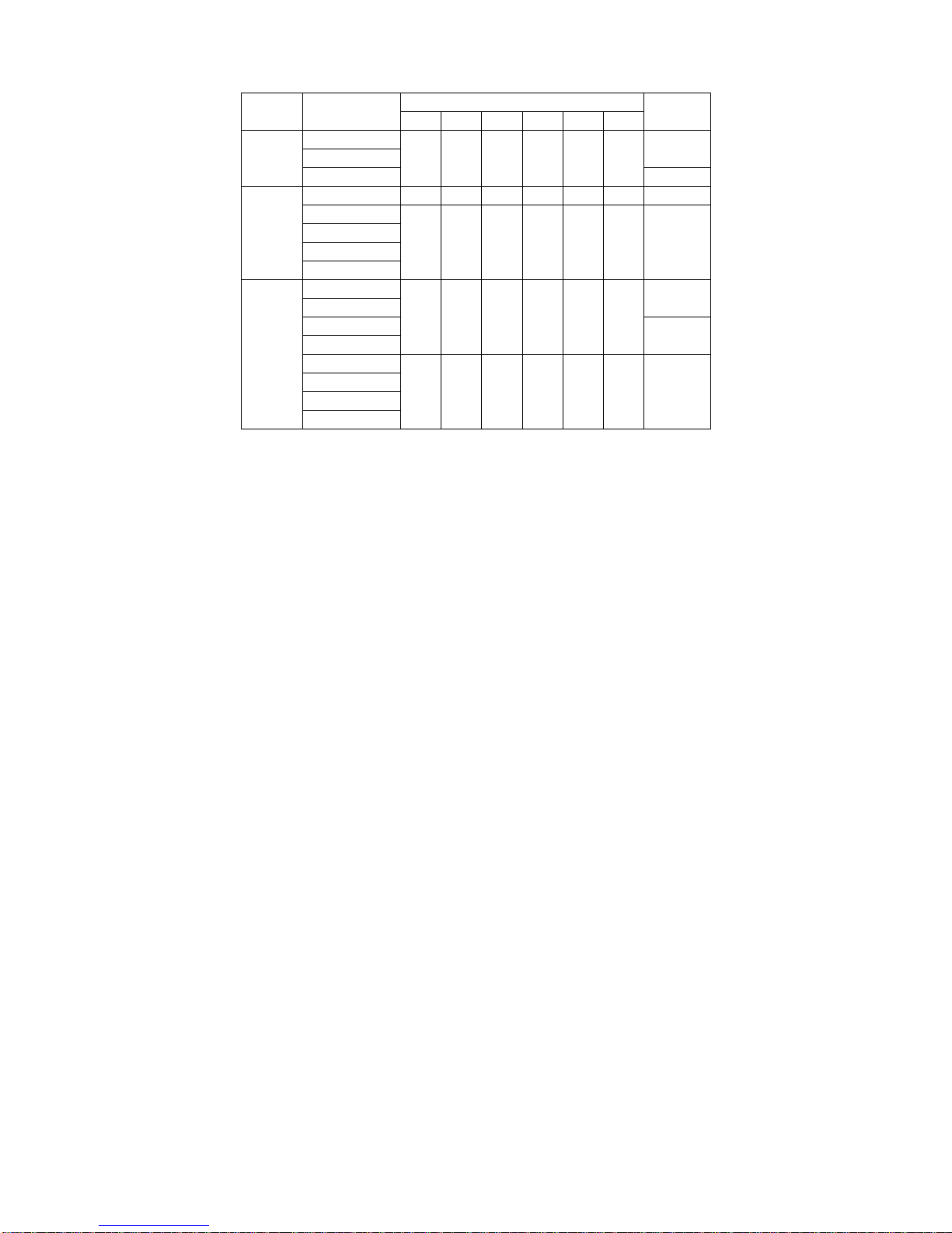
Voltage
230V
1/3Φ
230V
3Φ
460V
3Φ
Inverter
Capacity(HP)
WHDW1H1d
NEMA4 (mm)
1
2
198 335 217 115 315 M6
3
5 198 335 217 115 315 M6 7.5
7.5
10
15
223 460 245 140 440 M6 16
20
1
2
3
198 335 217 115 315 M6
5
7.5
10
15
223 460 245 140 440 M6 16
20
Weight
(kg)
6.3
7.5
6.3
7.5
1-21
Page 26
1-22
Page 27

1.10 Peripheral Units
■ Braking resistors
MA7200 230V/460V 1~20HP model have built-in braking transistor, and can be
connected external braking resistor between B1/P and B2 when lack of braking
ability. Above 25HP models, need to connect braking unit (on ⊕ - \ of inverter)
and braking resistors (on B-P0 of braking unit).
Table 4 Braking resistor list
Inverter Braking Unit Braking Resistor
Voltage HP
1 4.8 - - JNBR-150W200 150W/200Ω 1 119%, 10%ED
230V
1/3Φ
2 6.4 - - JNBR-150W100 150W/100Ω 1 119%, 10%ED
39.6 - - JNBR-260W70 260W/70Ω 1 115%, 10%ED
5 17.5 - - JNBR-390W40 390W/40Ω 1 119%, 10%ED
7.5 24 - - JNBR-520W30 520W/30Ω 1 108%, 10%ED
10 32 - - JNBR-780W20 780W/20Ω 1 119%, 10%ED
Rated
current (A)
Model
Number
used
Code NO. Specs.
Number
used
Braking Torque
(%)
230V
3Φ
460V
3Φ
15 48 - - JNBR-2R4KW13R6 2400W/13.6Ω 1 117%, 10 %ED
20 64 - - JNBR-3KW10 3000W/10Ω 1 119%, 10%ED
25 80 JNTBU-230 1 JNBR-4R8KW8 4800W/8Ω 1 11 9%, 10%ED
30 96 JNTBU-230 1 JNBR-4R8KW6R8 4800W/6.8Ω 1 11 7%, 10%ED
40 130 JNTBU-230 2 JNBR-3KW10 3000W/10Ω 2 11 9%, 10%ED
1 2.6 - - JNBR-150W750 150W/750Ω 1 126%, 10%ED
2 4 - - JNBR-150W400 150W/400Ω 1 119%, 10 %E D
34.8 - - JNBR-260W250 260W/250Ω 1 126%, 10%ED
58.7 - - JNBR-400W150 400W/150Ω 1 126%, 10%ED
7.5 12 - - JNBR-600W130 600W/130Ω 1 102%, 10%ED
10 15 - - JNBR-800W100 800W/100Ω 1 99%, 10%ED
15 24 - - JNBR-1R6KW50 1600W/50Ω 1 126%, 10%ED
20 32 - - JNBR-1R5KW50 1500W/40Ω 1 119%, 10%ED
25 40 JNTBU-430 1 JNBR-4R8KW32 4800W/32Ω 1 119%, 10%ED
30 48 JNTBU-430 1 JNBR-4R8KW27R2 4800W/27.2Ω 1 117%, 10%ED
40 64 JNTBU-430 1 JNBR-6KW20 6000W/20Ω 1 119%, 10%ED
50 80 JNVPHV-0060 1 JNBR-9R6KW16 9600W/16Ω 1 119%, 10%ED
60 96 JNVPHV-0060 1 JNBR-9R6KW13R6 9600W/13.6Ω 1 117 %, 10%ED
75 128 JNTBU-430 2 JNBR-6KW20 6000W/20Ω 2 126%, 10%ED
1-23
Page 28

■ AC reactor
• An AC reactor can be added on the power supply side if the inverter is connected to a
much larger capacity power supply system, or the inverter is within short distance
(<10m) from power supply systems, or to increase the power factor on the power
supply side.
• Choose the proper AC reactor according to the below list.
Table 5 AC reactor list
Inverter Model AC reactor
VHP
1 4.8A 3M200D1610021 2.1mH/5A
230V
1Φ/3Φ
2 6.5A 3M200D1610030 1.1mH/10A
3 9.6A 3M200D1610048 0.71mH/15A
5.4 17.5A 3M200D1610056 0.53mH/20A
7.5 24A 3M200D1610064 0.35mH/30A
10 32A 3M200D1610072 0.265mH/40A
230V
3Φ
15 48A 3M200D1610081 0.18mH/60A
20 64A 3M200D1610099 0.13mH/80A
25 80A
30 96A
40 130A
1 2.6A 3M200D1610137 8.4mH/3A
2 4A 3M200D1610145 4.2mH/5A
3 4.8A 3M200D1610153 3.6mH/7.5A
5.4 8.7A 3M200D1610161 2.2mH/10A
Rated
current
Code No.
3M200D1610102
3M200D1610111
3M200D1610269
Specification
(mH/A)
0.12mH/90A
0.09mH/120A
0.07mH/160A
7.5 12A 3M200D1610170 1.42mH/15A
10 15A 3M200D1610188 1.06mH/20A
460V
3Φ
15 24A 3M200D1610196 0.7mH/30A
20 32A 3M200D1610200 0.53mH/40A
25 40A
30 48A
40 64A
50 80A
60 96A
75 128A
Note: The AC reactors are applied only to input side. Do not apply it to output side.
3M200D1610218
3M200D1610226
3M200D1610234
3M200D1610242
3M200D1610251
3M200D1610315
1-24
0.42mH/50A
0.36mH/60A
0.26mH/80A
0.24mH/90A
0.18mH/120A
0.15mH/150A
Page 29
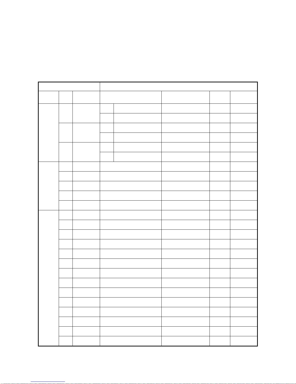
■ Noise filter
A. INPUT SIDE NOISE FILTER
• Installing a noise filter on power supply side to eliminate noise transmitted between
the power line and the inverter
• MA7200 has its specified noise filter to meet the EN61800-3 class A specification
Table 6 Noise filter on the input side
Inverter Noise Filter
VHP
Current (A)
1 4.8A
Rated
1Φ
3Φ
Code Specifications Current Dimensions
4H300D1750003 JUNF12015S-MA 15 A Fig. (a)
4H300D1710001 JUNF32012S-MA 12 A Fig. (a)
230V
1/3Φ
230V
3Φ
2 6.5A
1Φ
3Φ
1Φ
3 9.6A
3Φ
5.4 17.5A 4H300D1610007 JUNF32024S-MA 24 A Fig. (a)
7.5 24A 4H300D1620002 JUNF32048S-MA 48 A
10 32A 4H300D1620002 JUNF32048S-MA 48 A Fig. (b)
15 48A 4H300D1730002 JUNF32070S-MA 70 A Fig. (b)
20 64A 4H300D1730002 JUNF32070S-MA 70 A Fig. (b)
1 2.6A 4H300D1720007 JUNF34008S-MA 8 A Fig. (a)
2 4A 4H300D1720007 JUNF34008S-MA 8 A Fig. (a)
3 4.8A 4H300D1630008 JUNF34012S-MA 12 A Fig. (a)
5.4 8.7A 4H300D1630008 JUNF34012S-MA 12 A Fig. (a)
7.5 12A 4H300D1640003 JUNF34024S-MA 24 A Fig. (b)
10 15A 4H300D1640003 JUNF34024S-MA 24 A Fig. (b)
4H300D1750003 JUNF12015S-MA 15 A Fig. (a)
4H300D1710001 JUNF32012S-MA 12 A Fig. (a)
4H300D1600001 JUNF12020S-MA 20 A Fig. (a)
4H300D1610007 JUNF32024S-MA 24 A Fig. (a)
Fig. (b)
460V
3Φ
15 24A 4H300D1740008 JUNF34048S-MA 48 A Fig. (b)
20 32A 4H300D1740008 JUNF34048S-MA 48 A Fig. (b)
25 40A 4H000D1770008 KMF370A 70A Fig. (c)
30 48A 4H000D1790009 KMF370A 70A Fig. (c)
40 64A 4H000D1790009 KMF3100A 100A Fig. (c)
50 80A 4H000D1800004 KMF3100A 100A Fig. (c)
60 96A 4H000D1800004 KMF3150A 150A Fig. (c)
75 128A 4H000D1820005 KMF3180A 180A Fig. (c)
1-25
Page 30
• Dimension : (unit : mm)
2
φ
φ
(a) (b)
140
125
250
225
80
40
LINE
L1 L2 L3
PE
LOAD
L1 L2 L3
PE
−
60
6.5
100
50
LINE
L1 L2 L3
PE
LOAD
PE
6.5
4 −
L1 L2 L3
70
(c)
Model
WW1 H H1 D d M
KMF370A 93 79 312 298 190 7 M6
KMF3100A 93 79 312 298 190 7 M6
KMF3150A 126 112 334 298 224 7 M6
KMF3180A 126 112 334 298 224 7 M6
Dimension (mm)
1-26
Page 31

B. EMI SUPPRESSION ZERO PHASE CORE
0
• Model : JUNFOC046S -------
• Code No. : 4H000D0250001
• According to the required power rating and wire size, select the matched ferrite core to
suppress EMI noise.
• The ferrite core can attenuate the frequency response at high frequency range (from
100KHz to 50MHz, as shown below). It should be able to attenuate the RFI from
inverter to outside.
• The zero-sequence noise ferrite core can be installed either on the input side or on the
output side. The wire around the core for each phase should be winded by following
the same convention and one direction. The more winding turns the better attenuation
effect. (Without saturation). If the wire size is too big to be winded, all the wire can be
grouped and go through these several cores together in one direction.
• Frequency attenuation characteristics (10 windings case)
-10
-20
-30
atteuatoin value (dB)
-40
10
1
10
2
10
3
10
Interference Frequency (kHz)
Example: EMI suppression zero phase core application example
DRIVE FWD REV REMOTE
DIGITAL OPERATOR JNEP-31
PRGM
DSPL
DRIVE
EDIT
JOG
ENTER
FWD
RESET
REV
RUN STOP
4
10
5
Note: All the line wire of U/T1, V/T2, W/T3 phase must pass through the same zero-
phase core in the same winding sense.
1-27
Page 32

■ LCD operator with extension wire
When used for remote control purpose, the LCD operator can have different
extension wires based upon the applications. Some extension wires are listed below.
MA7200
L
Cable Length Extension Cable Set *1 Extension Cable *2 Blank Cover *3
1m 4H332D0010000 4H314C0010003
2m 4H332D0030001 4H314C0030004
3m 4H332D0020005 4H314C0020009
4H300D1120000
5m 4H332D0040006 4H314C0040000
10m 4H332D0130005 4H314C0060001
*1 : Including special cable for LCD digital operator, blank cover, fixed use screws and
installation manual.
*2
: One special cable for LCD digital operator.
*3
: A blank cover to protect against external dusts, metallic powder, etc.
The physical dimension of LCD digital operator is drawn below.
REMOT
FWDDRIVEREV
DIGITAL OPERATOR JNEP-3
PRG
M
DRIVE
JOG
FWD
REV
RUN
E
REF
SEQ
1
DSP
L
EDI
T
ENTER
RESET
STO
P
Fig. 6. LCD Digital Operator Dimension
1-28
Page 33

A
r
A
A
r
R/L1
A
S/L2
T/L3
Master Freq. Ref.
976Ω
2kΩ
BREAKER
FWD RUN
STOP
, 1/4 W
0 ~ 10V
FM
B1/P
R/L1
S/L2
T/L3
1
SC
(+15V, 20 mA)
15V Power Supply
for Speed Ref
VIN Master Speed
GND 0V
01
GND
MA7200
NALOG
OUTPUT
B2
U/T1
V/T2
W/T3
RA
RB
RC
IM
Multi-Function
Contact Output
250V AC, max. 1A
30V DC, max. 1A
■ Analog operator
All MA7200 have the
digital LCD digital operator.
DO1
During
Running
DO2
.
DOG
Speed
gree
Multi-Function
Output 1, 2
(Open Collecto
48V/50mA)
Moreover, an analog operator
as JNEP-16 (shown in fig. 7)
is also available and can be
connected through wire as a
nalog Operato
diagram is shown below.
Fig. 7. Analog Operator
■ PROFIBUS Communication Card
portable operator. The wiring
• Code No. : 4H300D0290009
• Please refer to the appendix D and “MA7200 PROFIBUS-DP Communication
Application manual” for communication interface.
1-29
Page 34

2. Using LCD Digital Operator
t
r
r
■ Functions of LCD digital operator
JNEP-36 LCD digital operator has 2 modes: DRIVE mode and PRGM mode. When
the inverter is stopped, DRIVE mode or PRGM mode can be selected by pressing
the key
PRGM
DRIVE
mode, the parameter settings for operation can be changed but the operation is not
enabled. The component names and function are shown as below:
. In DRIVE mode, the operation is enabled. Instead, in the PRGM
DRIVE FWD REV REMOTE
SEQ
REF
operation mode indicators
DRIVE : lit when in DRIVE mode
FWD : lit when there is a forward run command inpu
REV : lit when there is a reverse run command input
SEQ : lit when the run command is enabled from the
DIGITAL OPERATOR JNEP-36
control circuit terminal or RS-485 port (REMOTE mode)
REF : lit when the frequency reference from the control
REMOTE/LOCAL
circuit terminals (VIN or AIN) or RS-485 port is
enabled (REMOTE mode)
PRGM
DRIVE
DSPL
LCD Display
JOG
EDIT
ENTER
Chinese Display : 2-line by 8-characte
English Display : 2-line by 20-characte
FWD
REV
RESET
Keys (Key functions are defined in Table 7)RUN STOP
Fig. 8. LCD Digital operator
• Remote/Local switch function:
• Local mode – RUN command input from LCD Digital Operator (SEQ LED off)
– Frequency command input from LCD Digital Operator (REF LED
off)
• Remote mode –RUN command input from control circuit (when Sn-04=1) or RS-
485 comm. port (when Sn-04=2) (SEQ LED lit)
–Frequency command input from control circuit (when Sn-05=1) or
RS-485 comm. port (when Sn-05=2) (REF LED lit)
• Press and both to switch Local/Remote mode. (Switching action of
JOG
RESET
Local/Remote only can be done while Inverter stop.)
2-1
Page 35

Table 7 Key's functions
Key Name Function
PRGM
DRIVE
DSPL
JOG
FWD
REV
RESET
EDIT
ENTER
PRGM/DRIVE
key
DSPL key
JOG key
FWD/REV
key
RESET key
INCREMENT
key
DECREMENT
key
EDIT/ENTER
key
Switches over between program mode (PRGM) and drive
mode (DRIVE).
Display operation status
Enable jog operation from LCD digital operator in operation
(DRIVE).
Select the rotation direction from LCD digital operator.
Set the number of digital for user constant settings. Also It
acts as the reset key when a fault has occurred.
Select the menu items, groups, functions, and user constant
name, and increment set values.
Select the menu items, groups, functions, and user constant
name, and decrement set values.
Select the menu items, groups, functions, and user constants
name, and set values (EDIT). After finishing the above
action, press the key (ENTER).
RUN
RUN key
Start inverter operation in (DRIVE) mode when the digital
operator is used. The LED will light.
Stop inverter operation from LCD digital operator. The
STOP
STOP key
STOP key can be enabled or disabled by setting the
parameter Sn-07 when operating from the control circuit
terminal.
RUN,STOP indicator lights or blinks to indicate the 3 operating status:
Inverter output frequency
STOP
Frequency setting
RUN
STOP
STOP
ON
RUN
Blink
OFF
2-2
Page 36

■ Display contents in DRIVE mode and PRGM mode
Power on
PRGM mode
An-
□□
Bn-
□□
Sn-
□□
Cn-
□□
DSPL
monitor/set
DSPL
monitor/set
DSPL
monitor/set
DSPL
monitor/set
PRGM
DRIVE
DRIVE mode
Frequency reference
value displayed
display monitor/set item
Un-
□□
An-
□□
Bn-
□□
DSPL
*1
DSPL
DSPL
DSPL
monitor
DSPL
monitor/set
DSPL
monitor/set
DSPL
*3
RESET
*2
Sn-
Cn-
□□
□□
monitor
DSPL
monitor
*1 When the inverter is powered up, the inverter system immediately enters into DRIVE
mode. Press the
PRGM
DRIVE
occurs, press the
key, the system will switch into PRGM mode. If the fault
PRGM
DRIVE
key and enter into DRIVE mode to monitor the
corresponding Un-□□ contents. If a fault occurs in the DRIVE mode, the
corresponding fault will be displayed. Press the
key and reset the fault.
RESET
*2 The monitored items will be displayed according to the settings of Bn-12 and Bn-13.
*3 When in the DRIVE mod e, press the
DSPL
key and
key, the setting values of
RESET
Sn- and Cn-□□ will only be displayed for monitoring but not for changing or setting.
2-3
Page 37

■ Parameter description
The inverter has 4 groups of user parameters:
Parameters Description
An-□□ Frequency command
Bn-□□ Parameter groups can be changed during running
Sn-□□ System parameter groups (can be changes only after stop)
Cn-□□ Control parameter groups (can be changed only after stop)
The parameter setting of Sn-03 (operation status) will determine if the setting value
of different parameter groups are allowed to be changed or only to be monitored, as
shown below:
DRIVE mode PRGM mode
Sn-03
To be set To be monitored To be set To be monitored
*1
0
An,Bn Sn,Cn An,Bn,Sn,Cn
1 An Bn,(Sn,Cn)
*2
An Bn,Sn,Cn
-
*1 : Factory setting
*2 : When in DRIVE mode, the parameter group Sn-, Cn- can only be monitored if the
key and the
RESET
DSPL
key are to be pressed simultaneously.
*3 : After a few trial and adjustment, the setting value Sn-03 is set to be “1” so as not be
modified again.
2-4
Page 38

■ Example of using LCD digital operator
Note :
Before operation: Control parameter Cn-01 value must be set as the
input AC voltage value. For example, Cn-01=380 if
AC input voltage is 380.
This example will explain the operating of the inverter according to the following time
chart.
■ OPERATION MODE
(1)
(2) (3) (4) (5) (6) (7) (8)
FWD
60 Hz
STOP
POWER
ON
SET INPUT
VOLTAGE
FWD JOG
OPERATION
■ Example of operation
Description
When Power on
(1)
(2)
Input voltage
setting (e.g. AC
input voltage is
(continued)
380V )
Select frequency reference
value displayed
Select PRGM mode
Select
PARAMETER
CONTROL
Display Cn-01 setting
Input Voltage 380V
FWD RUN
FREQUENCY
SETTING
Key Sequence
PRGM
DRIVE
DSPL
EDIT
ENTER
RESET
EDIT
ENTER
REV RUN
FREQ REF.
VALUE CHANGED
Digital Operator
Freq. Cmd.000.00Hz
An -01
Freq. Cmd. 1
press 3
times
Input Voltage
Cn-01 = 440.0V
Input Volt age
Cn-01 = 380.0V
Input Volt age
Entry Accepted
Display
TECO
Cn -01-
REV
60Hz
Remark
LED
OFF
Display
for 0.5 sec
DRIVE
2-5
Page 39

(continued)
Description
Key Sequence
Digital Operator
Display
Remark
(3)
(4)
(5)
FWD JOG
Frequency setting
FWD run
15 Hz
Select DRIVE mode
Select output frequency
displayed
Select direction of rotation
(When power on, initially
defaulted FWD)
Jog operation
Select frequency cmd
displayed
Change frequency cmd
Set new frequency cmd
Select O/P frequency
displayed
Running operation
PRGM
DRIVE
DSPL
JOG
DSPL
RESET
EDIT
ENTER
DSPL
RUN
press
4 times
Freq. Cmd.000.00Hz
TECO
Freq. Cmd.0.00 Hz
O/P Freq. 0.00 Hz
O/P Freq. 6.00 Hz
Freq. Cmd. 6.00 Hz
Freq. Cmd.000.00Hz
TECO
Freq. Cmd.015.00Hz
TECO
Freq. Cmd.015.00Hz
TECO
Entry Accepted
O/P Freq. 0.00 Hz
Freq. Cmd. 15.00 Hz
O/P Freq. 15.00 Hz
Freq. Cmd. 15.00 Hz
DRIVE
LED
ON
FWD
LED
ON
Displayed for 0.5sec
Confirm the display.
LED
ON
RUN
(6)
Frequency
command change
(7)
(8)
REV RUN
STOP
Select frequency cmd
displayed
60 Hz
Change reference val u e
Enter new frequency cmd
setting
Select frequency cmd
displayed
Change to REV
Decrement to STOP
DSPL
RESET
EDIT
ENTER
DSPL
FWD
REV
STOP
press
4 times
Freq. Cmd.015.00Hz
TECO
Freq. Cmd.060.00Hz
TECO
Freq. Cmd.060.00Hz
TECO
Entry Accepted
O/P Freq. 60.00 Hz
Freq. Cmd. 60.00 Hz
O/P Freq. 60.00 Hz
Freq. Cmd. 60.00 Hz
O/P Freq. 0.00 Hz
Freq. Cmd. 60.00 Hz
Displayed for 0.5sec
Confirm the display.
LED
REV
ON
LED
STOP
ON
(Blinking
while
decel.)
RUN
2-6
Page 40

■ Example of display (use and keys to display monitored
items/contents)
Description
Display
Frequency Command
Display
Moniter Contents *1
Display
Output Current
Display
Output Voltage
Display
DC Voltage
Display
Output Voltage
Display
Output Current
Key Sequence
DSPL
Digital Operator
Display
Freq. Cmd. 60.00Hz
TECO
Freq. Cmd. 60.00 Hz
O/P Freq. 60.00 Hz
Freq. Cmd. 60.00 Hz
O/P I 12.5 A
Freq. Cmd. 60.00 Hz
O/P Volt. 220. 0 V
Freq. Cmd. 60.00 Hz
DC Volt. 310. 0 V
Freq. Cmd. 60.00 Hz
O/P Volt. 220. 0 V
Freq. Cmd. 60.00 Hz
O/P I 12.5 A
Remark
*1. The monitor contents can be selected by the setting of Bn-12 and Bn-13
2-7
Page 41

3. Parameter Setting
3.1 Frequency command (in Multi-speed operation) An*1-□□
Under the DRIVE mode, the user can monitor the parameters and set their values.
Parameter
No.
An-01 Frequency Command 1
An-02 Frequency Command 2
An-03 Frequency Command 3
An-04 Frequency Command 4
An-05 Frequency Command 5
An-06 Frequency Command 6
An-07 Frequency Command 7
An-08 Frequency Command 8
An-09 Frequency Command 9
An-10 Frequency Command 10
An-11 Frequency Command 11
An-12 Frequency Command 12
An-13 Frequency Command 13
An-14 Frequency Command 14
An-15 Frequency Command 15
An-16 Frequency Command 16
An-17
Name LCD Display (English) Setting Range
Jog Frequency
Command
An-01= 000.00Hz
Freq. Cmd. 1
An-02= 000.00Hz
Freq. Cmd. 2
An-03= 000.00Hz
Freq. Cmd. 3
An-04= 000.00Hz
Freq. Cmd. 4
An-05= 000.00Hz
Freq. Cmd. 5
An-06= 000.00Hz
Freq. Cmd. 6
An-07= 000.00Hz
Freq. Cmd. 7
An-08= 000.00Hz
Freq. Cmd. 8
An-09= 000.00Hz
Freq. Cmd. 9
An-10= 000.00Hz
Freq. Cmd. 10
An-11= 000.00Hz
Freq. Cmd. 11
An-12= 000.00Hz
Freq. Cmd. 12
An-13= 000.00Hz
Freq. Cmd. 13
An-14= 000.00Hz
Freq. Cmd. 14
An-15= 000.00Hz
Freq. Cmd. 15
An-16= 000.00Hz
Freq. Cmd. 16
An-17= 000.00Hz
Jog Freq. Cmd.
0.00~400.00Hz
0.00~400.00Hz
0.00~400.00Hz
0.00~400.00Hz
0.00~400.00Hz
0.00~400.00Hz
0.00~400.00Hz
0.00~400.00Hz
0.00~400.00Hz
0.00~400.00Hz
0.00~400.00Hz
0.00~400.00Hz
0.00~400.00Hz
0.00~400.00Hz
0.00~400.00Hz
0.00~400.00Hz
0.00~400.00Hz
Setting
*2
Factory
Unit
0.01Hz 0.00Hz
0.01Hz 0.00Hz
0.01Hz 0.00Hz
0.01Hz 0.00Hz
0.01Hz 0.00Hz
0.01Hz 0.00Hz
0.01Hz 0.00Hz
0.01Hz 0.00Hz
0.01Hz 0.00Hz
0.01Hz 0.00Hz
0.01Hz 0.00Hz
0.01Hz 0.00Hz
0.01Hz 0.00Hz
0.01Hz 0.00Hz
0.01Hz 0.00Hz
0.01Hz 0.00Hz
0.01Hz 6.00Hz 3-56
Setting
Ref.
Page
3-54
3-70
3-71
*1. At factory setting, the value of “Setting Unit” is 0.01Hz.
*2. The displayed “Setting Unit” can be changed through the parameter Cn-28.
3-1
Page 42

3.2 Parameters Groups Can Be Changed during Running Bn-□□
Under the DRIVE mode, the Parameter group can be monitored and set by the users.
Function
Acc/Dec
time
Analog
Frequency
Multi-
Function
Analog
Input
Torque
Boost
Monitor
Multi-
Function
Analog
Output
PID
Control
Parameter
No.
Bn-01 Acceleration Time 1
Bn-02 Deceleration Time 1
Bn-03 Acceleration Time 2
Bn-04 Deceleration Time 2
Bn-05
Bn-06
Bn-07
Bn-08
Bn-09
Bn-10
Bn-11 Auto Torque Boost Gain
Bn-12 Monitor 1
Bn-13 Monitor 2
Bn-14
Bn-15
Bn-16 PID Detection Gain
Bn-17 PID Proportional Gain
Bn-18 PID integral time
Bn-19 PID Differential Time
Bn-20 PID Bias
Analog Frequency Cmd
Analog Frequency Cmd
Multi-Function Analog
Multi-Function Analog
Multi-Function Analog
Multi-Function Analog
Name
Analog Frequency
Cmd. Gain (Voltage)
Analog Frequency
Cmd. Bias (Voltage)
Gain. (Current)
Bias (Current)
Input Gain
Input Bias
Output AO1 Gain
Output AO2 Gain
LCD display
(English)
Bn-01= 0010.0s
Acc. Time 1
Bn-02= 0010.0s
Dec. Time 1
Bn-03= 0010.0s
Acc. Time 2
Bn-04= 0010.0s
Dec. Time 2
Bn-05= 0100.0%
Voltage Cmd. Gain
Bn-06= 000.0%
Voltage Cmd. Bias
Bn-07= 0100.0%
Current Cmd. Gain
Bn-08= 000.0%
Current Cmd. Bias
Bn-09= 0100.0%
Multi_Fun. ~Gain
Bn-10= 000.0%
Multi_Fun. ~Bias
Bn-11= 0.5
Auto_Boost Gain
Bn-12= 01
Display: Freq.Cmd.
Bn-13= 02
Display: O/P Freq.
Bn-14= 1.00
~Output AO1 Gain
Bn-15= 1.00
~Output AO2 Gain
Bn-16= 01.00
PID Cmd. Gain
Bn-17= 01.00
PID P_gain
Bn-18= 10.00s
PID I_Time
Bn-19= 0.00s
PID D_Time
Bn-20= 0%
PID Bias
Setting range
0.0~6000.0s
0.0~6000.0s
0.0~6000.0s
0.0~6000.0s
0.0~1000.0%
-100.0%~100.0%
0.0~1000.0%
-100.0%~100.0%
0.0~1000.0%
-100.0%~100.0%
0.0~2.0
1~18
1~18
0.01~2.55
0.01~2.55
0.01~10.00
0.01~10.00
0.00~100.00s
0~1.00s
0~109%
Setting
Unit
0.1s 10.0s
0.1s 10.0s
0.1s 10.0s
0.1s 10.0s
0.10% 100.00%
0.10% 0.00%
0.10% 100.00%
0.10% 0.00%
0.10% 100.00%
0.10% 0.00%
0.1 0.5 3-5
0.01 1
0.01 1
0.01 1
0.01 1
0.01s 10.00s
0.01s 0.00s
1% 0%
Factory
Setting
11
12
Ref.
Page
3-4
3-5
3-5
3-6
3-7
3-7
3-2
Page 43

Auto_Run
Time
Function
Timer
Function
Energy
Saving
Parameter
No.
Bn-21
Bn-22
Bn-23
Bn-24
Bn-25
Bn-26
Bn-27
Bn-28
Bn-29
Bn-30
Bn-31
Bn-32
Bn-33
Bn-34
Bn-35
Bn-36
1st_Step Time Under
2nd_Step Time Under
3rd_Step Time Under
4th_Step Time Under
5th_Step Time Under
6th_Step Time Under
7th_Step Time Under
8th_Step Time Under
9th_Step Time Under
10th_Step Time Under
11th_Step Time Under
12th_Step Time Under
13th_Step Time Under
14th_Step Time Under
15th_Step Time Under
16th_Step Time Under
Bn-37
Bn-38
Bn-39 Energy_Saving Gain
Name
Auto_Run Mode
Auto_Run Mode
Auto_Run Mode
Auto_Run Mode
Auto_Run Mode
Auto_Run Mode
Auto_Run Mode
Auto_Run Mode
Auto_Run Mode
Auto_Run Mode
Auto_Run Mode
Auto_Run Mode
Auto_Run Mode
Auto_Run Mode
Auto_Run Mode
Auto_Run Mode
Timer Function
On_Delay Time
Timer Function
Off_Delay Time
Monitor Bn-40 Monitor 3
LCD display
(English)
Bn-21= 0000.0s
Time 1
Bn-22= 0000.0s
Time 2
Bn-23= 0000.0s
Time 3
Bn-24= 0000.0s
Time 4
Bn-25= 0000.0s
Time 5
Bn-26= 0000.0s
Time 6
Bn-27= 0000.0s
Time 7
Bn-28= 0000.0s
Time 8
Bn-29= 0000.0s
Time 9
Bn-30= 0000.0s
Time 10
Bn-31= 0000.0s
Time 11
Bn-32= 0000.0s
Time 12
Bn-33= 0000.0s
Time 13
Bn-34= 0000.0s
Time 14
Bn-35= 0000.0s
Time 15
Bn-36= 0000.0s
Time 16
Bn-37= 0000.0s
ON_delay Setting
Bn-38= 0000.0s
OFF_delay Setting
Bn-39= 100%
Eg.Saving Gain
Bn-40=00
Display : Set_Freq.
Setting range
0.0~6000.0s
0.0~6000.0s
0.0~6000.0s
0.0~6000.0s
0.0~6000.0s
0.0~6000.0s
0.0~6000.0s
0.0~6000.0s
0.0~6000.0s
0.0~6000.0s
0.0~6000.0s
0.0~6000.0s
0.0~6000.0s
0.0~6000.0s
0.0~6000.0s
0.0~6000.0s
0.0~6000.0s
0.0~6000.0s
50~150%
Setting
Unit
0.1s 0.0s
0.1s 0.0s
0.1s 0.0s
0.1s 0.0s
0.1s 0.0s
0.1s 0.0s
0.1s 0.0s
0.1s 0.0s
0.1s 0.0s
0.1s 0.0s
0.1s 0.0s
0.1s 0.0s
0.1s 0.0s
0.1s 0.0s
0.1s 0.0s
0.1s 0.0s
0.1s 0.0s
0.1s 0.0s
1% 100% 3-10
Factory
Setting
00~18 1 0 3-10
Ref.
Page
3-70
3-71
3-9
3-3
Page 44

Pulse
Input
PID
Feedback
Display
Parameter
No.
Name
Bn-41 Pulse Input Upper Limit
Bn-42 Pulse Input Gain
Bn-43 Pulse Input Bias
Bn-44 Pulse Input Delay Time
PID Feedback Display
*1
Bn-45
Bn-46
PID Feedback Display
*1
at 0%
at 100%
LCD display
(English)
Bn-41=1440 Hz
Pulse_Mul._Up_Bound
Bn-41=100.0 %
Pulse_Mul._Gain
Bn-41=000.0 %
Pulse_Mul._Bias
Bn-41=0.10 s
Pulse_Mul._Filter
Bn-45= 0000
PID Display at 0%
Bn-46= 1000
PID Display at 0%
Setting range
Setting
Unit
Factory
Setting
1440~32000 1 Hz 1440
0.0~1000.0 0.10% 100
-100.0~100.0 0.1Hz 0
0.00~2.00 0.01s 0.1
1~9999
1~9999
*1
*1
*2
1
*2
1
0
1000
Page
*1. These parameters are available for 74.03 and later software version only.
*2. The displayed “Setting Unit” and “Setting Range” can be changed through parameter Cn-28 and
Sn-70.
(1) Acceleration Time 1 (Bn-01)
(2) Deceleration Time 1 (Bn-02)
(3) Acceleration Time 2 (Bn-03)
(4) Deceleration Time 2 (Bn-04)
• Set individual Acceleration/Deceleration times
• Acceleration time: the time required to go from 0% to 100% of the maximum
output frequency
• Deceleration time: the time required to go from 100% to 0% of the maximum
output frequency
• If the acceleration/deceleration time sectors 1 and 2 are input via the multi-function
inputs terminal g~j, the acceleration/Deceleration can be switched between 2
sectors even in the running status.
Output frequency
Ref.
3-11
3-11
Cn-02
Bn-01
Bn-03
Note :
1. To set the S-curve characteristics function, please refer to the description of Cn-41~Cn-44.
2. The S-curve characteristic times can be set respectively for beginning-accel. end-accel.,
beginning-decel., and end-decel. through the parameters setting of Cn-41~Cn-44.
Control circuit terminals
Open :
Close :
Bn-02
Bn-04
select the 1st sector Acc./Dec. time
(Parameters Bn-01, Bn-02 set)
select the 2nd sector ACC/DEC time
(Parameters Bn-03, Bn-04 set)
Time
Fig. 9. Acceleration and Deceleration time
3-4
~
Page 45

(5) Analog Frequency Command Gain (Voltage) (Bn-05)
(6) Analog Frequency Command Bias (Voltage) (Bn-06)
(7) Analog Frequency Command Gain (Current) (Bn-07)
(8) Analog Frequency Command Bias (Current) (Bn-08)
(9) Multi-function Analog Input Gain (Bn-09)
(10) Multi-function Analog Input Bias (Bn-10)
• For every different analog frequency command (voltage or current) and multi-
function analog inputs, their corresponding gain and bias should be specified
respectively.
command value
Max. output
frequency
Max. output
frequency
gain
100
bias
100
0V
(4 mA)
10V
(20 mA)
Input voltage
(Input current)
* ( ) If current
command is used
Fig. 10. Analog input gain and bias
(11) Auto Torque Boost Gain (Bn-11)
• The inverter can increase the output torque to compensate the load increase
automatically through the auto torque boost function. Then the output voltage will
increase. As a result, the fault trip cases can be decreased. The energy efficiency is
also improved. In the case that the wiring distance between the inverter and the
motor is too long (e.g. more than 100m), the motor torque is a little short because of
voltage drop. Increase the value of Bn-11 gradually and make sure the current will
not increase too much. Normally, no adjustment is required.
output
voltage
100 %
torque
increase
Fig. 11. Adjust the auto torque boost gain Bn-11 to increase the output torque.
• If the driven motor capacity is less than the inverter capacity (Max. applicable
motor capacity), raise the setting.
• If the motor generates excessive oscillation, lower the setting.
torque
decrease
Base frequency
3-5
Page 46

(12) Monitor 1 (Bn-12)
(13) Monitor 2 (Bn-13)
• In the DRIVE mode, 2 inverter input/output statuses can be monitored at the same
time. The specified items can be set through the setting of Bn-12 and Bn-13. For
more details, refer to Table 8.
• Example:
(1) Bn-12= 02
Bn-13= 01
Display O/P Freq. 15.00Hz
Freq.Cmd. 15.00Hz
(2) Bn-12= 03
Bn-13= 05
(3) Bn-12= 11
Bn-13= 12
Display O/P I 21.0A
DC Volt 311V
Display I/P Term. 00101010
O/P Term. 00010010
Note : While monitoring, use the or key to show the next lower-row
displayed. But the setting of Bn-12 and Bn-13 does not change.
Table 8 Setting of Monitoring contents
Setting
Bn-12= 01 Freq.Cmd. Bn-13= 01 Freq.Cmd.
Bn-12= 02 O/P Freq. Bn-13= 02 O/P Freq.
Bn-12= 03 O/P I Bn-13= 03 O/P I
Bn-12= 04 O/P V Bn-13= 04 O/P V
Bn-12= 05 DC Volt Bn-13= 05 DC Volt
Bn-12= 06 Term. VIN Bn-13= 06 Term. VIN
Bn-12= 07 Term. AIN Bn-13= 07 Term. AIN
Bn-12= 08 Term. AUX Bn-13= 08 Term. AUX
Bn-12= 09 ~ Output(AO1) Bn-13= 09 ~ Output(AO1)
Bn-12= 10 ~ Output(AO2) Bn-13= 10 ~ Output(AO1)
Bn-12= 11 I/P Term Bn-13= 11 I/P Term
Bn-12= 12 O/P Term Bn-13= 12 O/P Term
Bn-12= 13 Sp. FBK Bn-13= 13 Sp. FBK
Bn-12= 14 Sp. Compen. Bn-13= 14 Sp. Compe n.
Bn-12= 15 PID I/P Bn-13= 15 PID I/P
Bn-12= 16 PID O/P(Un-16) Bn-13= 16 PID O/P(Un-16)
Bn-12= 17 PID O/P(Un-17) Bn-13= 17 PID O/P(Un-17)
Bn-12= 18 Motor Sp. Bn-13= 18 Motor Sp.
Monitoring
contents
Setting
Monitoring
contents
3-6
Page 47

(14) Multi-function Analog Output AO1 Gain (Bn-14)
(15) Multi-function Analog Output AO1 Gain (Bn-15)
• Multi-function analog output AO1 and AO2 can be set for their individual voltage
level respectively.
Multi-functional analog output AO1
(output contents depend on Sn-33)
Multi-functional analog output AO2
( output contents depend on Sn-34)
10.0 V * Bn-14
10.0 V * Bn-15
Terminal
AO1
Terminal
AO2
(16) PID Detection Gain (Bn-16)
(17) PID Proportional Gain (Bn-17)
(18) PID Integral Time (Bn-18)
(19) PID Differential Time (Bn-19)
(20) PID Bias (Bn-20)
• The PID control function is a control system that matches a feedback value (i.e., a
detected value) to the set target value. Combining the proportional (P), integral (I)
and derivative (D) control make the control possible to achieve required response
with the constant setting and tuning procedure of proportional gain Bn-17, integral
time Bn-18 and derivative time Bn-19.
• See the appendix on page App.1 for “PID Parameter Setting”.
• Fig. 12 is a Block diagram of the inverter’s internal PID control.
• If both the target value and feedback value are set to 0, adjust the inverter output
frequency to zero.
Target
value
(multi-functional
analog input terminal
Aux when Sn-29 = 09)
Detected value
Ref. Com.terminal¡G
Vin 0 ~ 10 V (Sn-24 = 0)
Ain 4 ~ 20mA (Sn-24 = 1)
while PID enabled
Bn-16
(P)
Bn-17
(I)
Bn-18
(D)
Bn-19
PID control input
(Un-15)
integral
upper_limit
Cn-55
Upper_limit
(+/- 109 %)
PID control O/P 1
Bn-20
(Un-16)
Bias
1st order delay
constant
Cn-56
Freq. Com.
PID control O/P 2
(Un-17)
Fig. 12. Block diagram for PID control in inverter
(For the version before 30.17)
3-7
Page 48

Deviation
Target value
(P)
(I)
(D)
Deviation
Bn-18
Deviation
20 ms
Detected value
t
Fig. 13. Response of PID control for step-shape (deviation) input
• Deviation = Target value-Detected value ×Bn-16.
• P’s control output = deviation ×Bn-17.
• I’s control output will increase with time and the output will be equal to the
deviation after time specified by parameter Bn-18
The parameter Cn-55 will prevent the calculated value of the integral control (with
the integral time Bn-18) in the PID control from exceeding the fixed amount.
Bn-19
D’s control output = difference × (
)
5 m sec
Note: The enable PID function, parameter Sn-64 must be set to 1
30.18 newly revised version inverter develops 8 PID control modes as following description:
0: Unavailable
1: (Positive characteristic) input of differential controller is balance of feedback value
and frequency value.
2: (Positive characteristic) input of differential controller is feedback value
3: (Positive characteristic) refers to frequency and PID control output. Input of
differential controller is balance of feedback value and frequency value.
4: (Positive characteristic) refers to frequency and PID control output. Input of
differential controller is feedback value
5: (Negative characteristic) input of differential controller is balance of feedback value
and frequency value.
6: (Negative characteristic) input of differential controller is feedback value
7: (Negative characteristic) refers to frequency and PID control output. Input of
differential controller is balance of feedback value and frequency value.
8: (Negative characteristic) refers to frequency and PID control output. Input of
differential controller is feedback value.
3-8
Page 49

PID control
output 1 (Un-16)
+
+
Fig. 14. PID Control Block diagram (After Version 30.18)
(21) Time Setting in Auto_Run Mode (Bn-21~Bn-36)
• In Auto_Run mode, the time setting for individual step is described on “(Sn-44~60)
auto run mode selection and enable”.
(22) Timer ON_Delay Time (Bn-37)
(23) Timer OFF_Delay Time (Bn-38)
• The timer function is enabled when the timer function input setting (Sn-25~28=19)
and its timer function output setting (Sn-30~32=21) are set for the multi-function
input and output respectively.
• These inputs and outputs serve as general-purpose I/O. Setting ON/OFF delay time
(Bn-37/38) for the timer can prevent chattering of sensors, switches and so on.
• When the timer function input ON times is longer than the value set for Bn-37, the
timer function output turns ON.
• When the timer function input OFF time is longer than the value set for Bn-38, the
timer function output turns OFF. An example is shown below.
Timer function input
Timer function output
ON ON
ON ON
Bn-37 Bn-37Bn-38 Bn-38
Fig. 15. An operation example of timer function
3-9
Page 50

(24) Energy Saving Gain (Bn-39)
• Input the energy saving command while a light load causes the inverter output
voltage to be reduced and save energy. Set this value as a percentage of the V/F
pattern. The setting range is 50~150%. The factory setting is 100% and the energy
saving function is disabled. If the energy saving gain Bn-39 is not 100%, the energy
saving function is enabled.
• In energy saving mode (Bn-39≠100), the output voltage will automatically
decrease and be proportional to energy saving gain Bn-39. The Bn-39 setting
should not be small so that the motor will not stall.
• The energy saving function is disabled in the PID close-loop control and during
acceleration and deceleration.
Run command
V/f(Cn-01 & Cn-08) * Bn-39
Output voltage
0.1 sec 0.1 sec
Fig. 16. Time chart for energy-saving operation
(25) Monitor 3 (Bn-40)
• The parameter sets immediate display content as power on.
• When Bn-40 = 00, inverter power on, the first line will display frequency
command, while the second line will display characters “TECO” as following
diagram:
Freq . Cmd. : 15.00 Hz
TECO
• When Bn-40≠00, that is Bn-40=01~18, LCD will display the set monitor items
while inverter power on. The first line display content is determined by Bn-12. The
second line is determined by Bn-40 as following diagram:
Set Bn-12=01
Bn-40=02
Freq . Cmd. : 15.00 Hz
O / P Freq.: 00.00 Hz
• Bn-40=01~18 parameter description is same with Bn-12, Bn-13.
Please refer to Table 1, Monitor item set.
3-10
Page 51

(26) Pulse Input setting (Bn-41~Bn-44)
• Setting Sn-05=3 before starting Pulse Input function. Please refer to Sn-05.
• Please refer to the following figure:
Upper Limit 100%
External Input
Frequency
Bn-44
Pulse Input
Delay
Command Value
Max. Output Freq.
Max. Output Freq.
×
×
Bn-41
Pulse Input
Upper Limit
Bn-42
100
Bn-43
100
0%
Upper Limit 100%
Command Value
100% Input Freq.
(27) PID Feedback Display at 0% (Bn-45)
(28) PID Feedback Display at 100% (Bn-46)
• These parameters are available for 74.03 and later software version only.
• The PID feedback can be input from control terminal VIN (0~10V) or AIN (4-
20mA).
• The PID feedback value can be monitored by the monitoring parameter Un-34.
The display content can be set by Cn-28, Sn-70, Bn-45 and Bn-46.
Cn-28 sets the decimal point position of Un-34.
Sn-70 sets the unit of Un-34.
Bn-45 is the equivalent value displayed for 0% PID Feedback.
Bn-46 is the equivalent value displayed for 100% PID Feedback.
Target
PID
Primary
Delay
Frequency
Command
Feedback
Signal
Bn-16
Bn-45,46
• The decimal point position and the unit of Bn-45, Bn-46 can be set by Cn-28 and
Sn-70. It is necessary to set the value of Cn-28 and Sn-70 before Bn-45 and Bn-46
are set.
• Ex PID feedback signal is pressure signal. 0% for 5.0 PSI, and 100% for 100.0 PSI.
Set Sn-70 = 3 (unit as PSI)
Cn-28 = 10000 (1 decimal)
Bn-45 = 005.0PSI (display at 0%)
Bn-46 = 100.0PSI (display at 100%)
PID Feedback Display
(Un-34)
3-1 1
Page 52

3.3 Control Parameters Cn-□□
Function
V/F
Pattern
Setting
Motor
Parameter
DC Braking
Function
Frequency
Limit
Frequency
Jump
Parameter
No.
Name
Cn-01 Input Voltage
Cn-02 Max. Output Frequency
Cn-03 Max. Output Voltage
Cn-04 Max. Voltage Frequency
Cn-05 Middle Output Frequency
Cn-06
Voltage At Middle Output
Frequency
Cn-07 Min Output Frequency
Cn-08
Voltage At Min. Output
Frequency
Cn-09 Motor Rated Current
Cn-10
No Load Current Of
Motor
Cn-11 Rated Slip Of Motor
Cn-12
Cn-13
Cn-14
Line-To-Line Resistance
Of Motor
Torque Compensation Of
Core Loss
DC Injection Braking
Starting Frequency
Cn-15 DC Braking Current
Cn-16
Cn-17
Cn-18
Cn-19
DC Injection Braking
Time At Stop
DC Injection Braking
Time At Start
Frequency Command
Upper Bound
Frequency Command
Lower Bound
Cn-20 Frequency Jump Point 1
Cn-21 Frequency Jump Point 2
Cn-22 Frequency Jump Point 3
Cn-23 Jump Frequency Width
LCD display
(English)
Cn-01= 230.0V
Input Voltage
Cn-02= 060.0Hz
Max. O/P Freq.
Cn-03= 230.0Hz
Max. Voltage
Cn-04= 060.0Hz
Max. Volt Frequency
Cn-05= 003.0Hz
Middle O/P Freq.
Cn-06= 014.9V
Middle Voltage
Cn-07= 001.5Hz
Min O/P Freq.
Cn-08= 007.9V
Min. Voltage
Cn-09= 0003.3A
Motor Rated I
Cn-10= 30%
Motor No-Load I
Cn-11= 0.0%
Motor Rated Slip
Cn-12= 05.732Ω
Motor Line R
Cn-13= 0064W
Core Loss
Cn-14= 01.5Hz
C Braking Start F
Cn-15= 050%
DC Braking Current
Cn-16= 00.5s
DC Braking Stop Time
Cn-17= 00.0s
DC Braking Start Time
Cn-18= 100%
Freq.Cmd. Up Bound
Cn-19= 000%
Freq. Cmd. Low Bound
Cn-20= 000.0Hz
Freq. Jump 1
Cn-21= 000.0Hz
Freq. Jump 2
Cn-22= 000.0Hz
Freq. Jump 3
Cn-23= 01.0Hz
Freq. Jump Width
Setting range
150.0~255.0V
Setting
*2
50.0~400.0Hz
0.1~255.0V
*2
0.1~400.0Hz
0.1~400.0Hz
0.1~255.0V
*2
0.1~400.0Hz
0.1~255.0V
*2
*3 0.1A 3.3A
0~99%
0~9.9%
0~65.535Ω
0.001Ω 5.732
0~65535W
0.1~10.0 Hz
0~100%
0.0~25.5s
0.0~25.5s
0~109%
0~109%
0.0~400.0Hz
0.0~400.0Hz
0.0~400.0Hz
0.0~25.5Hz
Factory
Unit
Setting
0.1V 230.0V
0.1Hz 60.0Hz
0.1V 230.0V
0.1Hz 60.0Hz
0.1Hz 3.0Hz
0.1V 15.5V
0.1Hz 1.5Hz
0.1V 8.2V
1% 30%
0.10% 0.00%
1W 64
*4
0.1Hz 1.5Hz
1% 50%
0.1s 0.5s
0.1s 0.0s
1% 100%
1% 0%
0.1Hz 0.0Hz
0.1Hz 0.0Hz
0.1Hz 0.0Hz
0.1Hz 1.0Hz
*1
*4
*1
*4
*1
*1
Ref.
Page
3-15
3-15
3-15
3-16
3-17
3-17
3-18
3-18
3-12
Page 53

Function
Retry
Function
Stall
Prevention
Parameter
No.
Cn-24
Cn-25
Cn-26
Name
Number of Auto Restart
Attempt
Stall Prevention During
Acceleration
Stall Prevention During
Running
LCD display
(English)
Cn-24= 00
Retry Times
Cn-25= 170%
Acc. Stall
Cn-26= 160%
Run Stall
Setting range
0~10
30~200%
30~200%
Setting
Unit
Factory
Setting
103-19
1% 170%
1% 160%
Ref.
Page
3-20
Comm.
Fault
detection
Display
Unit
Frequency
Agree
Detection
Torque
Detection 1
Carrier
Frequency
Speed
Search
Control
Cn-27
Cn-28
Cn-29
Cn-30
Cn-31
Cn-32
Cn-33
Communication Fault
Detection Time
LCD Digital Operator
Display Unit
Freq. Agree Detection
Level During Accel.
Freq. Agree Detection
Level During Decel.
Frequency Agree
Detection Width
Torque
Detection Level 1
Torque
Detection Time 1
Cn-34 Carrier frequency setting
Cn-35
Speed Search Detection
Level
Cn-36 Speed Search Time
Cn-37 Min. Baseblock Time
Cn-38
V/F Curve in Speed
Search
Cn-27=01.0s
Comm. Flt Det. Time
Cn-28= 00000
Operator Disp. Unit
Cn-29= 000.0Hz
Acc. Freq. Det.Level
Cn-30= 000.0Hz
Dec. Freq. Det. Level
Cn-31= 02.0Hz
F Agree Det. Width
Cn-32= 160%
Tq. Det. Level 1
Cn-33= 00.1s
Tq. Det. Time 1
Cn-34= 6
Carry_Freq Setting
Cn-35= 150%
Sp-Search Level
Cn-36= 02.0s
Sp-Search Time
Cn-37= 0.5s
Min. B.B. Time
Cn-38= 100
Sp-search V/F Gain
0.1~25.5s 0.1s 1s 3-20
0-39999 1 0 3-21
0.0~400.0Hz
0.0~400.0Hz
0.1~25.5Hz
0.1Hz 0.0Hz
0.1Hz 0.0Hz
0.1Hz 2.0Hz
0~200% 1% 160%
0.0~25.5s 0.1s 0.1s
1~6
0~200%
0.1~25.5s
0.5~5.0s
10~100%
163-24
1% 150%
0.1s 2.0s
0.1s 0.5s
1% 100%
3-22
3-23
3-24
Low
Voltage
Cn-39
Detection
Slip Comp. Cn-40
Cn-41
Cn-42
S-curve
time
Cn-43
Cn-44
Low Voltage Alarm
Detection Level
Slip Compensation
Primary Delay Time
S-curve Characteristic
Time at Accel. Start
S-curve Characteristic
Time at Accel. End
S-curve Characteristic
Time at Decel. start
S-curve Characteristic
Time at Decel. end
Cn-39= 200V
Low Volt. Det. Level
Cn-40= 02.0s
Slip Filter
Cn-41= 0.0s
S1 Curve Time
Cn-42= 0.0s
S2 Curve Time
Cn-43= 0.0s
S3 Curve Time
Cn-44= 0.0s
S4 Curve Time
3-13
150~210V
0.0~25.5s
0.0~1.0s
0.0~1.0s
0.0~1.0s
0.0~1.0s
1V 200V
*1
3-26
0.1s 2.0s 3-26
0.1s 0.0s
0.1s 0.0s
3-26
0.1s 0.0s
0.1s 0.0s
Page 54

Speed
feedback
control
PID
Control
Sensorless
Vector
Control
Torque
Detection 2
Parameter
No.
Name
Cn-45 PG Parameter
Cn-46 Pole no. of Motor
Cn-47 ASR Proportional Gain 1
Cn-48 ASR Integral Gain 1
Cn-49 ASR Proportional Gain 2
Cn-50 ASR Integral Gain 2
Cn-51 ASR Upper Bound
Cn-52 ASR Lower Bound
Cn-53
Cn-54
Cn-55
Cn-56
Cn-57
Cn-58
Cn-59
Cn-60
Excessive Speed
Deviation Detection Level
Overspeed Detection
Level
PID Integral Upper
Bound
PID Primary Delay Time
Constant
Motor Line-to-Line
Resistance (R1)
Motor Rotor Equivalent
Resistance (R2)
Motor Leakage
Inductance (Ls)
Motor Mutual
Inductance (Lm)
Cn-61 Slip Compensation Gain
Cn-62
Cn-63
*5
*5
Torque
Detection Level 2
Torque
Detection Time 2
LCD display
(English)
Cn-45= 0000.0
PG Parameter
Cn-46= 04P
Motor Pole
Cn-47= 0.00
ASR Gain 1
Cn-48= 01.0s
ASR Intgl. Time 1
Cn-49= 0.02
ASR Gain 2
Cn-50= 01.0s
ASR Intgl. Time 2
Cn-51= 05.0%
ASR Up Bound
Cn-52= 00.1%
ASR Low Bound
Cn-53= 10%
Sp.Deviat. Det.Level
Cn-54= 110%
Over Sp.Det. Level
Cn-55= 100%
PID I-Upper
Cn-56= 0.0s
PID Filter
Cn-57= 02.233Ω
Mtr LINE_R
Cn-58= 01.968Ω
Mtr ROTOR_R
Cn-59= 9.6mH
Mtr LEAKAGE_X
Cn-60= 149.7mH
Mtr MUTUAL_X
Cn-61= 1.00
SLIP GAIN
Cn-62= 160%
Tq. Det. Level 1
Cn-63= 00.1s
Tq. Det. Time 1
Setting range
0.0~3000.0P/R
2~32P
0.00~2.55
0.1~10.0S
0.00~2.55
0.1~10.0S
0.1~10.0%
0.1~10.0%
1~50%
1~120%
0~109%
0.0~2.5s
0.001~60.000Ω
0.001~60.000Ω
0.01~200.00mH
0.1~6553.5mH
0.00~2.55
Setting
Unit
0.1P/R 0.0P/R
2P 4P
0.01 0
0.1s 1.0s
0.01 0.02
0.1s 1.0s
0.10% 5.00%
0.10% 0.10%
1% 10%
1% 110%
1% 100%
0.1s 0.0s
0.001Ω 2.233Ω*43-28
0.001Ω 1.968Ω
0.01mH 9.6mH
0.1mH 149.7mH
0.01 1
0~200% 1% 160%
0.0~25.5s 0.1s 0.1s
Factory
Setting
Ref.
Page
3-27
3-28
3-28
*4
*4
3-29
*4
3-23
*1 These are for a 230V class inverter. Value(*1) for a 460V class inverter is double.
*2 These are for a 230V class inverter. Value(*2) for a 460V class inverter is double.
*3 The setting range is 10% ~200% of the inverter rated current.
*4 The factory setting values will vary based upon the inverter capacity selection (Sn-01) value. In
this case, the setting is for 4-pole, 230V, 60Hz, 1Hp TECO standard induction motors.
*5. These parameters are available for 74.03 and later software version only.
3-14
Page 55

(1) Input Voltage Setting (Cn-01)
• Set inverter voltage to match power supply voltage at input side (e.g. : 200V/230V,
380V/415V/440V/460V)
(2) V/F Curve Parameter Settings (Cn-02~Cn-08)
• The V/F curve can be set to either one of the preset curves (setting Sn-02=0~14)
or a customer user-set curve (setting Sn-02=15).
• Setting Cn-02~Cn-08 can be set by the user when Sn-02 has been set to “15”. The
user-defined V/F curve can be specified through the settings of Cn-02~Cn-08 as
shown in Fig. 17. The factory setting is straight line for the V/F curve. (Cn-05=Cn07, Cn-06 is not used) as shown below (230V/60Hz case).
Voltage
Voltage
(Factory Setting)
Cn-03
Cn-06
Cn-08
(Cn-08=Cn-06)
0
Cn-07
Cn-05
Cn-04
Cn-02
Freq.
220V
Cn-03
13
0
1.5 Hz
(Cn-07=Cn-05) (Cn-04=Cn-02)
60 Hz
Freq.
Fig. 17. User-defined V/F curve
• In low speed operation (<3Hz), a larger torque can be generated by increasing the
slope of V/F curve. However, the motor will be hot due to over-excitation. At the
same time the inverter will be more inclined to fault. Based upon the applied load,
properly adjust the V/F curve according to the magnitude of monitored current into
the motor.
• The four frequency settings must satisfy the following relationship, otherwise an
error message “V/F Curve Invalid” will display.
(a)
Max. output freq.≧ Max. voltage freq. > Mid. Output freq. ≧ Min. output freq.
(Cn-02) (Cn-04) (Cn-05) (Cn-07)
(b) Max. output volt.≧ Mid. output volt. > Min. output voltage
(Cn-03) (Cn-06) (Cn-08)
• If Mid. Output frequency (Cn-05) = Min. output frequency (Cn-07), the setting
(Cn-06) is not effective.
(3) Motor Rated Current (Cn-09)
• Electronic overload thermal reference current
• The factory setting depends upon the capacity type of inverter (Sn-01).
• The setting range is 10%~200% of the inverter rated output current.
• Set the rated current shown on the motor name plate if not using the TECO 4-pole
motor.
3-15
Page 56

(4) Motor No-Load Current (Cn-10)
• This setting is used as a reference value for torque compensation function.
• The setting range is 0~99% of the inverter rated current Cn-09 (100%).
• The slip compensation is enabled when the output current is greater than motor no-
load current (Cn-10). The output frequency will shift from f1 to f2 (>f1) for the
positive change of load torque. (See Fig. 18)
Slip compensation =
Motor rated current (Cn-09) – Motor no-load current (Cn-10)
Load torque
f1
smaller load
f2
larger load
speed
Fig. 18. Output frequency with slip compensation.
(5) Motor Rated Slip (Cn-11)
• This setting is used as a reference value for torque compensation function. See Fig.
17. The setting is 0.0~9.9% as a percentage of motor Max. voltage frequency (Cn-
04) as 100%.
Motor rated slip (Cn-11) ×(Output current – Motor no-load current(Cn-10))
• The setting is shown in Fig. 19 in the constant torque and constant output range. If
setting Cn-11 is zero, no slip compensation is used.
• There is no slip compensation in the cases when the frequency command is less
than the Min. output frequency or during regeneration.
Motor rated slip (Cn-11) =
Cn-02
Cn-04
Motor rated freq. (Hz) ×(Rated speed(RPM) – Motor No. of poles)
×100%
Max-voltage freq (Cn-04) ×120
Cn-11
Cn-11
Cn-02Cn-04
Fig. 19. Slip compensation limit
3-16
Page 57

(6) Motor Line-to-Line Resistance (Cn-12)
(7) Motor Iron-Core Loss (Cn-13)
• It is for torque compensation function. The default setting depends upon the
inverter capacity (Sn-01). Normally, the setting does not need to be altered. See
Table 10~11 on page 3-39.
(8) DC Injection Braking Starting Frequency (Cn-14)
(9) DC Injection Braking Current (Cn-15)
(10) DC Injection Braking Time at Stop (Cn-16)
(11) DC Injection Braking Time at Start (Cn-17)
• The DC injection braking function decelerates by applying a DC current to the
motor. This happens in the 2 cases:
a. DC injection braking time at start: It is effective for temporarily stopping and then
restarting, without regeneration, a motor coasting by inertia.
b. DC injection braking time at stop: It is used to prevent coasting by inertia when the
motor is not completely stopped by normal deceleration when there is a large load.
Lengthening the DC injection braking time (Cn-16) or increasing the DC injection
braking current (Cn-15) can shorten the stopping time.
• For the DC injection braking current (Cn-15), set the value for the current that is
output at the time of DC injection braking. DC injection braking current is set as a
percentage of inverter rated output current, with the inverter rated output current
taken as 100%.
• For the DC injection braking time at start (Cn-17), set the DC injection braking
operating time when the motor is started.
• For the DC injection braking starting frequency (Cn-14), set the frequency for
beginning DC injection braking for deceleration. If the excitation level is less than
the Min. output frequency (Cn-07), the DC injection braking will begin from Min.
output frequency.
• If the DC injection braking time at start (Cn-17) is 0.0, the motor starts from the
Min. output frequency and no DC injection braking are enabled.
• If the DC injection braking time at stop (Cn-16) is 0.0, no DC injection braking is
enabled. In this case, the inverter output will be blocked off when the output
frequency is less than the DC injection braking at start frequency (Cn-14).
Cn-07
Min. output frequency
Cn-17
DC injection braking at st ar t
Cn-14
DC injection braking
starting frequency
Cn-16
DC injection braking at st op
Fig. 20. DC injection braking time chart
3-17
Page 58

(12) Frequency Command Upper Bound (Cn-18)
(13) Frequency Command Lower Bound (Cn-19)
• The upper and lower bounds of the frequency command are set as a percentage of
the Max. output frequency (Cn-02 as 100%), in increments of 1%.
• The relationship Cn-18 > Cn-19 must be abided by. If not, an error message “Freq.
Limit Setting Error” may occur.
• When the frequency command is zero and a run command is input, the motor
operates at the frequency command lower bound (Cn-19). The motor will not
operate, however, if the lower limit is set lower than the Min. output frequency (Cn-
07).
Output frequency
100%
Cn-18
Cn-19
frequency command
100%
Fig. 21. Upper and lower bounds of the frequency command
(14) Frequency Jump Point 1 (Cn-20)
(15) Frequency Jump Point 2 (Cn-21)
(16) Frequency Jump Point 3 (Cn-22)
(17) Jump Frequency Width (Cn-23)
• These settings allow the “jumping” of certain frequencies within the inverter’s
output frequency range so that the motor can operate without resonant oscillations
caused by some machine systems.
Output
frequency
Cn-21
Cn-22 Cn-23
Cn-23
Cn-20
Cn-23
22-Cn 21-Cn 20-Cn ≥≥
Set frequency command
Fig. 22. setting jump frequencies
3-18
Page 59

• Operation is prohibited within the jump frequency range, but changes during
acceleration and deceleration are smooth with no jump. To disable this function, set
the jump frequency 1~3 (Cn-20~Cn-22) to 0.0Hz.
• For the jump frequency 1~3 (Cn-20~Cn-22), set the center frequency to be
jumped.
• Be sure to set the jump so that Cn-20 ≥ Cn-21 ≥ Cn-22. If not, a message “Jump
frequency setting error” is displayed. For Cn-23, set the jump frequency bandwidth.
If Cn-23 is set as 0.0Hz, the jump frequency function is disabled.
(18) Number of Auto Restart Attempt (Cn-24)
• The fault restart function will restart the inverter even when an internal fault occurs
during inverter operation. Use this function only when continuing operation is more
important than possibly damaging the inverter.
• The fault restart function is effective with the following faults. With other faults, the
protective operations will engage immediately without attempting to restart
operation.
• Over-current •Ground fault •Main circuit over-voltage
• The fault restart count will automatically increase upon the restart activated and
will be cleared in the following cases:
a. When the operation is normal for 10 minutes after a fault restart is performed.
b. When the fault-reset input is received after the protection operation has been
activated and the fault confirmed. (e.g., by pressing
terminal
e)
or enable Fault reset
RESET
c. When the power is turned off and on again.
• When one of the multi-function output terminals (RA-RB-RC or R1A-R1B-R1C,
DO1, DO2 or R2A-R2C) is set to restart enabled, the output will be ON while the
fault restart function is in progress. See page 63 for the setting of (Sn-30~Sn-32).
3-19
Page 60

(19) Stall Prevention Level During Acceleration (Cn-25)
(20) Stall Prevention Level During Running (Cn-26)
• A stall occurs if the rotor can not keep up with the rotating electromagnetic field in
the motor stator side when a large load is applied or a sudden acceleration or
deceleration is performed. In this case, the inverter should automatically adjust the
output frequency to prevent stall.
• The stall prevention function can be set independently for accelerating and running.
• Stall Prevention During Acceleration: See Fig.23. Stop acceleration if Cn-25 setting
is exceeded. Accelerate again when the current recovers.
• Stall Prevention During running : See Fig.24. Deceleration is started if the run stall
prevention level Cn-26 is exceeded, especially when an impact load is applied
suddenly. Accelerate again when the current level is lower than Cn-26.
Load
current
Load
current
Cn-25
Output
frequency
The output frequency is
controlled to prevent stalling
Fig. 23 Acceleration stall prevention
Time
Time
Cn-26
Output
frequency
decreases to prevent stalling
Deceleration time
upon Bn-02, Bn-04
The output frequency
Time
Time
Fig. 24 Run stall prevention function
function
• Set the parameters Cn-25 and Cn-26 as a percentage of inverter rated current (100%
corresponds to inverter rated current).
• See page 3-48, 3-49 for stall prevention function selection.
(21) Communication Fault Detection Time (Cn-27)
• Please refer to “MODBUS/PROFIBUS Application Manual”.
3-20
Page 61

(22) LCD Digital Operator Display Unit (Cn-28)
• It sets the units to be displayed for the frequency command and frequency
monitoring. and sets the decimal points of PID feedback display (Un-34), PID
feedback display at 0% and 100% (Bn-45, 46) as described below:
Table 9 LCD digital Operator Display unit
Setting / Reading Content
Cn-28
Frequency command/monitoring PID Feedback
0 Units of 0.01 Hz
1 Units of 0.01%
2 to 39
40 to
39999
Set in the units of r / min (0 to 39999).
r / min = 120 x frequency reference (Hz) /
Cn-28
(Set the number of motor poles in Cn-28,
only even data is allowed)
The position of decimal point is set by the
value of the 5th digit of Cn-20.
5th digit = 0: Displayed as XXXX
5th digit = 1: Displayed as XXX.X
5th digit = 2: Displayed as XX.XX
5th digit = 3: Displayed as X.XXX
The 1st digit to 4th digits of Cn-28 set the
value of 100% frequency.
Displayed as XXXX
Unit specified by Sn-70
y 5th digit = 0:
Displayed as XXXX
y 5th digit = 1:
Displayed as XXX.X
y 5th digit = 2:
Displayed as XX.XX
y 5th digit = 3:
displayed as X.XXX
The 1
st
digit to 4
th
digits of Cn-28 are not
used.
• Example 1:
When the set value of 100% speed is 200.0, Cn-28 = 12000 is set.
60% speed is displayed as 120.0 at Cn-28 = 12000.
• Example 2:
When the set value of 100% speed is 65.00, Cn-28 = 26500 is set.
60% speed is displayed as 39.00 at Cn-28 = 26500.
Unit specified by Sn-70
3-21
Page 62

(23) Frequency Agree Detection Level During Acceleration (Cn-29)
(24) Frequency Agree Detection Level During Deceleration (Cn-30)
(25) Frequency Agree Detection Width (Cn-31)
• Frequency detection function: Set the multi-function output terminals (control
circuit terminals RA-RB-RC or R1A-R1B-R1C, DO1, DO2 or R2A-R2C) to output
the desired Frequency Agree signal, Setting Frequency Agree and Output
Frequency Detection level (through proper setting of Sn-30 ~ Sn-32).
• The time chart for Frequency Detection operation is described as follows:
Function Frequency Detection Operation Description
• When output freq. is within freq.
command +/- freq. Detection width
(Cn-31), frequency agree output is
“ON”.
•Set Sn-30~Sn-32 to be “02” for the
setting of frequency agree output.
Frequency
Agree
freq. command
output freq.
freq. agree
signal output
Cn-31
FWD
REV
Cn-31
ONOFF
Setting
Frequency
Agree
Output
Frequency
Detection 1
Output
Frequency
Detection 2
freq. command
output freq.
agree freq.
signal output
output freq.
output freq.
detection 1 signal
output freq.
output freq.
detection 2 signal
OFF
Cn-29
Cn-29
Cn-31
ON
Cn-31
ON OFF
Cn-31
OFF
Cn-31
Cn-31
ONONOFF
Cn-31
Cn-31
ON OFF ON OFF
Cn-29
Cn-30
Cn-29
Cn-30
Cn-29
FWD
REV
FWD
Cn-30
Cn-31
FWD
Cn-30
Cn-31
•After acceleration, the output freq.
reaches freq. Agree detection level
during acceleration (Cn-29) and within
freq. Agree detection width (Cn-31),
agreed freq. output is “ON”.
•Set Sn-30~Sn-32 to be “03”.
•During acceleration, the output freq. is
less than freq. agree detection level
during acceleration (Cn-29), output
freq. Detection 1 is “ON”.
•During deceleration, the output freq. is
REV
less than freq. agree detection level
during deceleration (Cn-30), output
freq. Detection 1 is “ON”.
•Set Sn-30~Sn-32 to be “04” for the
setting of output freq. detection.
•During acceleration, the output freq. is
larger than freq. Agree detection level
during acceleration (Cn-29), output
freq. detection 2 is “ON”.
•During deceleration, the output freq. is
REV
larger than freq. Agree detection level
during deceleration (Cn-30), output
freq. detection 2 is “ON”.
•Set Sn-30~Sn-32 to be “05” for the
setting of output freq. detection.
3-22
Page 63

(26) Torque Detection Level 1 (Cn-32)
(27) Torque Detection Time 1 (Cn-33)
(28) Torque Detection Level 2 (Cn-62)
(29) Torque Detection Time 2 (Cn-63)
• Cn-62, 63 are available for 74.03 and later software version only.
• Both Overtorque Detection Function and Undertorque Detection Function are
included in Torque Detection Function. The Overtorque Detection Function detects
excessive mechanical load from an increase of output current. The Undertorque
Detection Function detects broken fan belt from a decrease of output current.
• An overtorque 1 condition is detected when the output current exceeds the Torque
Detection Level (Cn-32, Cn-62) for longer than the Torque Detection Time 1 (Cn33, Cn-63). See Fig.25-a below.
• An undertorque condition is detected when the output current is lower than the
Torque Detection Level (Cn-32, Cn-62) for longer than the Torque Detection Time
(Cn-33, Cn-63). See Fig.25-b below.
• When Torque Detection 1 is enabled through the setting Sn-12, be sure to set
Torque Detection Level 1 (Cn-32) and Torque Detection Time 1 (Cn-33).
• The Multi-Function Output Terminals (Control Circuit Terminals RA-RB-RC or
R1A-R1B-R1C, DO1, DO2 or R2A-R2C) can be set to indicate an overtorque
condition or an undertorque condition has been detected.
Motor
Current
Cn-32
Overtorque
Detection Signal
Cn-33
ON
ON
Cn-33
Hysteresis
Width 5%
Fig. 25-a. Overtorque Detection Time Chart
Motor
Current
Cn-32
Hysteresis
Width 5%
Undertorque
Detection Signal
Fig. 25-b. Underorque Detection Time Chart
ON
Cn-33
3-23
ON
ON
Cn-33
Page 64

• Properly setting the value of Sn-12 (Torque Detection 1 Selection) and Sn-69
(Torque Detection 2 Selection) and will allow
a. Enable only during frequency agreement. Continue operation even after detection.
b. Enable only during frequency agreement. Stop operation after detection.
c. Enable at anytime. Continue operation even after detection.
d. Enable at anytime. Stop operation after detection.
(30) Carrier Frequency Setting (Cn-34)
• Lower the carrier frequency can decrease the noise interference and leakage
current. Its setting is shown below.
Carrier frequency(kHz) = 2.5kHz* Cn-34 setting
Cn-34 =
1 2 6*543
(2.5 kHz) (15 kHz)
Carrier frequency
Audio noise
(louder) (insensible)
*factory setting
• The output frequency does not need to be adjusted, except in the following cases.
a. If the wiring distance between the inverter and motor is long, lower the carrier
frequency as shown below to allow less leakage current.
Wring distance < 100ft. 100-165ft. 166-328ft.
>
329ft.
Carrier frequency (Cn-34) <15kHz <10kHz <5KHz <2.5KHz
b. If there is great irregularity in speed or torque, lower the carrier frequency.
(31) Speed Search Detection Level (Cn-35)
(32) Speed Search Time (Cn-36)
(33) Min. Baseblock Time (Cn-37)
(34) Speed Search V/F Curve (Cn-38)
• The speed search function will search the speed of a frequency coasting motor from
the frequency command or max. frequency downward. And it will restart up
smoothly from that frequency or max. frequency. It is effective in situations such as
switching from a commercial power supply to an inverter without tripping
occurred.
• The timing of speed search function as shown below :
3-24
Page 65

FWD(or REV) run command
Speed search command
<0.5 sec
Max output frequency
(or running frequency
while the speed search
is being performed)
Output frequency
Min baseblock time
voltage at speech search
ouput voltage
speed search operation
Synchronous speed dectection
retuen to voltage at
normal operation
Fig. 26. Speed search timing chart
• The speed search command can be set through the multi-function contact input
terminal g ~ j (By setting the parameters Sn-25 ~ Sn-28).
If Sn-25 ~ Sn-28= 21 : Speed search is performed from Max. output frequency
and motor is coasting freely.
If Sn-25 ~ Sn-28= 22 : Speed search starts from the frequency command when the
speed search command is enabled.
• After the inverter output is blocked, the user should input speed search command
then enable run operation, the inverter will begin to search the motor speed after the
min. baseblock time Cn-37.
• Speed search operation, if the inverter output current is less than Cn-35, the inverter
will take the output frequency as the real frequency at that time. From those values
of real frequency, the inverter will accelerate or decelerate to the set frequency
according to the acceleration or deceleration time.
• While the speed search command is being performed, the user can slightly decrease
the setting of V/F curve (Cn-38) in order to prevent the OC protection function
enabled. Normally, the V/F curve need not be changed. (As below)
• Speed search operating V/F curve = Cn-38 * (normal operating V/F curve )
Note : 1. The speed search operation will be disabled if the speed search command is
enacted from the Max. frequency and the setting frequency. (I.e., Sn-25=20, Sn26=21 and multi-function input terminals g, h is used at the same time).
2. Make sure that the FWD/REV command must be performed after or at the
3-25
Page 66

same time with the speed search command. A typical operation sequence is
shown below.
Ry1
Speed search command
Ry1
Ry2
RWD/REV run command
3. When the speed search and DC injection braking are set, set the Min.
baseblock time (Cn-37). For the Min. baseblock time, set the time long
enough to allow the motor’s residual voltage to dissipate. If an overcurrent is
detected when starting a speed search or DC injection braking, raise the
setting Cn-37 to prevent a fault from occurring. As a result, the Cn-37 setting
cannot be set too small.
(35) Low Voltage Alarm Detection Level (Cn-39)
• In most cases, the default setting Cn-39 need not be changed. If an external AC
reactor is used, decrease the low voltage alarm detection level by adjusting Cn-39
setting smaller. Be sure to set a main-circuit DC voltage so that a main circuit
undervoltage is detected.
(36) Slip Compensation Primary Delay Time (Cn-40)
• In most cases, the setting Cn-40 need not be changed. If the motor speed is not
stable, increase the Cn-40 setting. If the speed response is slow, decrease the setting
of Cn-40.
(37) S-curve Characteristic Time at Acceleration Start (Cn-41)
(38) S-curve Characteristic Time at Acceleration End (Cn-42)
(39) S-curve Characteristic Time at Deceleration Start (Cn-43)
(40) S-curve Characteristic Time at Deceleration End (Cn-44)
• Using the S-curve characteristic function for acceleration and deceleration can
reduce shock to the machinery when stopping and starting. With the inverter, Scurve characteristic time can be set respectively for beginning acceleration, ending
acceleration, beginning deceleration and ending deceleration. The relation between
these parameters is shown in Fig. 27.
3-26
Page 67

Run
•
•
command
Output
frequency
ON
S2
OFF
S3
S1
Cn-41
Cn-42 Cn-43
S4
Cn-44
Time
Fig. 27. S curve
• After the S-curve time is set, the final acceleration and deceleration time will be as
follows:
(Cn-41) + (Cn-42)
Acc. time = selected Acc. Time 1 (or 2) +
2
(Cn-43) + (Cn-44)
Dec. time = selected Dec. Time 1 (or 2) +
2
(41) PG Parameter (Cn-45)
• The parameter is set in the unit of pulse/revolution. The factory setting is 0.1 P/R.
(42) Pole Number of Motor (Cn-46)
• Cn-45 and Cn-46 must meet the following relationship:
2 * Cn-45 * Cn-02
< 32767
Cn-46
• If not, an error message “Input Error” will be displayed
(43) ASR Proportion Gain 1 (Cn-47)
(44) ASR Integral Gain 1 (Cn-48)
• Set the proportion gain and integral time of the speed control (ASR)
(45) ASR Proportion Gain 2 (Cn-49)
(46) ASR Integral Gain 2 (Cn-50)
• Use these constants to set different proportional gain and integral time settings for
high-speed operation.
3-27
Page 68

Proportional gain
Integral time
Cn-49
Cn-47
0 % 100 %
Output
frequency
Cn-50
Cn-48
0 % 100 %
Output
frequency
Fig. 28.
(47) ASR Upper Bound (Cn-51)
(48) ASR Lower Bound (Cn-52)
• These settings of Cn-51 and Cn-52 will limit the ASR range.
(49) Excessive Speed Deviation Detection Level (Cn-53)
• This parameter set the level of detecting PG speed deviation. The value of Cn-02 is
referred as 100%, the default unit setting is 1%.
(50) Overspeed Detection Level (Cn-54)
• Set this parameter for detecting overspeed. The value of Cn-02 is referred as 100%,
the default unit setting is 1%. Please refer to the setting of Sn-43.
(51) PID Integral Upper Bound (Cn-55)
(52) PID Primary Delay Time Constant (Cn-56)
• Please refer to Fig. 14 “Block diagram for PID control in inverter”
• The parameter Cn-55 prevents the calculated value of the integral control of PID
from exceeding the fixed amount. The value is limited within 0-109% of Max.
output frequency (100%). Increase Cn-55 will improve the integral control. If
hunting cannot be reduced by decreasing the Bn-18 or increasing Cn-56, Cn-55 has
to decrease. If the setting of Cn-55 is too small, the output may not match the target
setting.
• The parameter Cn-56 is the low-pass filter setting for PID control output. If the
viscous friction of the mechanical system is high, or if the rigidity is low, causing
the mechanical system to oscillate, increase the setting Cn-56 so that it is higher
than the oscillation period. It will decrease the responsiveness, but it will prevent
the oscillation.
(53) Motor Line-to-Line Resistance R1 (Cn-57)
• Set the motor’s terminal resistance (including the motor external cable resistance)
in Ω unit.
• The default setting depends upon the type of inverter (but do not include the motor
external motor cable resistance).
3-28
Page 69

• This value will be automatically set during autotuning. See “Motor parameter
autotuning selection” on page 3-73.
• Increase the setting when the generating torque is not large enough at low speed.
• Decrease the setting when the generating torque is extremely high and cause
overcurrent trip at low speed.
(54) Motor Rotor Equivalent Resistance R2 (Cn-58)
• Set the motor’s rotor Y-equivalent model resistance in unit.
• The default setting depends upon the type of inverter. Normally this value isn’t
shown on the motor’s nameplate, so it might be necessary to contact motor
manufactor.
• This value will be automatically set during autotuning. See “Motor parameter
autotuning selection” on page 3-73.
(55) Motor Leakage Inductance Ls (Cn-59)
• Set the motor’s rotor Y-equivalent model leakage inductance in mH unit.
• The default setting depends upon the type of inverter.
• This value will be automatically set during autotuning. See “Motor parameter
autotuning selection” on page 3-73.
(56) Motor Mutual Inductance Lm (Cn-60)
• Set the motor Y-equivalent model mutual inductance in mH unit.
• The default setting depends upon the type of inverter.
• This value will be automatically set during autotuning. See “Motor parameter
autotuning selection” on page 3-73.
Note: The Induction Motor Y-equivalent model
LsR1
I
d
L
m
(57) Slip Compensation Gain (Cn-61)
• The parameter Cn-61 improves speed accuracy while operating with a load.
• Usually, the setting Cn-61 need not be changed. Adjust the setting if the speed
accuracy is needed to improve.
• When actual speed is low, increase the set value.
I
q
R2
s
s : slip
• When actual speed is high, decrease the set value.
3-29
Page 70

3.4 System Parameters Sn-□□
Function
Capacity
Setting
V/F Curve Sn-02
Operator
Status
Operation
Control
Mode
Selection
Parameter
No.
Sn-01
Sn-03 Operator Display
Sn-04
Sn-05
Sn-06
Sn-07
Sn-08
Sn-09
Name
Inverter Capacity
Selection
V/F Curve
Selection
Run Source
Selection
Frequency
Command
Selection
Stopping
Method
Selection
Priority of
Stopping
Prohibition of
REV Run
Output Frequency
Up/Down Function
LCD display
(English)
Sn-01= 01
220V 1HP
Sn-02= 01
V/F curve
Sn-03= 00
Setting Valid
Sn-04= 0
Run source
Operator
Sn-05= 0
Ref. Cmd.
Operator
Sn-06= 0
Dec. Stop
Sn-07= 0
Stop Key Valid
Sn-08= 0
Allow Reverse
Sn-09= 0
Inhibit UP/DOWN
Description
Inverter capacity selection *1 3-39
0~14 : 15 fixed V/F curve pattern
15 : arbitrary V/F pattern selection
0 : An-□□, Bn-□□, Cn-□□, Sn-□□ setting
& reading enabled
1 : An-□□, setting & reading enabled
Bn-□□,Cn-□□,Sn-□□ reading only
2~5 : reserved
6 : clear fault message
7 : 2-wire initialization (230V/460V)
8 : 3-wire initialization (230V/460V)
9 : 2-wire initialization (200V/415V)
10 : 3-wire initialization (200V/415V)
11 : 2-wire initialization (200V/380V)
12 : 3-wire initialization (200V/380V)
13~15 : reserved
Run source
0 : Operator
1 : Control terminal
2 : RS-485 communication
Frequency Command
0 : Operator
1 : Control circuit terminal
2 : RS-485 communication
0 : Deceleration to Stop
1 : Coast to Stop
2 : Whole_range braking stop
3 : Coast to Stop with Timer
(restart after time Bn-02)
If operation command from control terminal
or RS-485 communication port
0 : operator stop key effective
1 : operator stop key not effective
0 : reverse run enabled
1 : reverse run disabled
0 : Reference frequency is changed
through the key ”UP/DOWN” pressing,
later followed by key “EDIT/ENTER”
pressing, and then this output freq. will
be acknowledged.
1 : reference frequency will be
acknowledged immediately after the key
”UP/DOWN” pressing.
Factory
Setting
0
0
0
0
0
0
Ref.
Page
3-40
3-43
3-43
3-45
3-30
Page 71

Function
Operation
Control
Mode
Selection
Protection
Charac-
teristic.
selection
Parameter
No.
Sn-10
Sn-11
Sn-12
Sn-13
Sn-14
Sn-15
Name
Frequency
Command
Characteristics
Selection
Scanning Times at
Input Terminal
Torque Detection
1 Selection
Output Voltage
Limit Selection
Stall Prevention
During Acc.
Function
Selection
Stall Prevention
During Dec.
Function
Selection
LCD display
(English)
Sn-10= 0
Ref. Cmd. Fwd.
Char.
Sn-11= 0
Scan Time 5 ms
Sn-12= 0
Tq.Detect Invalid
Sn-13= 0
V Limit Invalid
Sn-14= 1
Acc. Stall Valid
Sn-15= 1
Dec. Stall Valid
Description
0 : Reference command has forward
characteristics
(0~10V or 4~20mA/0~100%
1 : Reference command has reverse
characteristics
(10~0V or 20~4mA/0~100%)
0 : scan and confirm once per 5 ms
1 : continuously scan and confirm twice per
10 ms
Option 5-8 are available for 74.03 and later
software version only.
0 : Torque detection function 1 is not
effective.
1 : Overtorque is detected only at
frequency agree. Continue operation
after detection.
2 : Overtorque is detected only at
frequency agree. Stop operation after
detection.
3 : Overtorque is detected during running
(Accel.,Decel. included). Continue
operation after detection.
4 : Overtorque is detected during running
(Accel., Decel included). Stop operation
after detection.
5 : Undertorque is detected only at
frequency agree. Continue operation
after detection.
6 : Undertorque is detected only at
frequency agree. Stop operation after
detection.
7 : Undertorque is detected during running
(Accel.,Decel. included). Continue
operation after detection.
8 : Overtorque is detected during running
(Accel., Decel included). Stop operation
after detection.
0 : V/F output voltage is limited
1 : V/F output voltage is not limited
0 : invalid (Too much a torque may cause
the stall)
1 : valid (stop acceleration if current
exceeds Cn-25 setting)
0 : invalid (installed with external brake
unit)
1 : valid (no external brake unit used)
Factory
Setting
0
0
0
0
1
1
Ref.
Page
3-46
3-47
3-48
3-31
Page 72

Function
Protection
Charac-
teristic.
selection
Protection
Charac-
teristic.
Selection
Parameter
No.
Sn-16
Sn-17
Sn-18
Sn-19
Sn-20
Sn-21
Sn-22
Sn-23
Sn-24
Name
Stall Prevention
During Running
Function Selection
Fault Retry
Setting
Operation
Selection At
Power Loss
Zero Speed
Braking Operation
Selection
External Fault
Contact e
Contact Selection
External Fault
Contact e
Detection
Selection
External Fault
Operation
Selection
Motor Overload
Protection
Selection
Frequency
Command
Characteristics
Selection at
External Analog
Input Terminal
LCD display
(English)
Sn-16= 1
Run Stall Valid
Sn-17= 0
Retry No O/P
Sn-18= 0
PwrL_to_ON Stop
O/P
Sn-19= 0
Z_braking Invalid
Sn-20= 0
Term.3 NO_Cont.
Sn-21= 0
All Time Ext. Fault
Sn-22= 1
Ext. Fault Free run
Sn-23= 1
Cold Start Over
Load
Sn-24= 0
~ Cmd. VIN
Description
0 : invalid
1 : valid –Deceleration time1 for stall
prevention during running (no external
brake unit used)
2 : valid –Deceleration time2 for stall
prevention during running (no external
brake unit used)
0 : Do not output fault retry.
(The fault contact does not operate.)
1 : Output fault retry.
(The fault contact operates.)
0 : stop running
1 : continue to run
(analog) Speed reference is 0 during
running on, the braking function selection
0 : invalid
1 : valid
0 : A-contact (normally open input)
1 : B-contact (normally close input)
0 : detect all time
1 : detect only during operation
0 : dec. to stop (upon dec. time1 Bn-02)
1 : coast (free run) to stop
2 : dec. to stop (upon dec. time1 Bn-04)
3 : continue operating
Electronically motor overload protection
selection
0 : electronically motor overload protection
invalid
1 : standard motor cold start overload
protection characteristics
2 : standard motor hot start overload
protection characteristics
3 : special motor cold start overload
protection characteristics
4 : special motor hot start overload
protection characteristics
Frequency command characteristics
selection at external analog input terminal
0 : voltage signal 0~10V (VIN)
1 : current signal 4~20mA (AIN)
2 : addition of voltage signal 0~10V and
current signal 4~20 mA (VIN+AIN)
3 : subtraction of current signal 4~20mA
and voltage signal 0~10V (VIN-AIN)
Factory
Setting
1
0
0
0
0
0
1
1
0 3-51
Ref.
Page
3-49
3-50
3-32
Page 73

Function
Multi-
function
Input
Contact
Selection
Multi-
function
Analog
Input
Selection
Multi-
function
Digital
Output
Selection
Multi-
function
Analog
Output
Selection
Parameter
No.
Sn-25
Sn-26
Sn-27
Sn-28
Sn-29
Sn-30
Sn-31
Sn-32
Sn-33
Sn-34
Name
Multi-Function
Input Terminal g
Function Selection
Multi-Function
Input Terminal h
Function Selection
Multi-Function
Input Terminal i
Function Selection
Multi-Function
Input Terminal j
Function Selection
Multi-Function
Analog Input
(AUX) Function
Selection
Multi-Function
Output Terminal
(RA-RB-RC)
Function Selection
Multi-Function
Output Terminal
(DO1) Function
Selection
Multi-Function
Output Terminal
(DO2) Function
Selection
Multi-Function
Analog Output
(AO1) Function
Selection
Multi-Function
Analog Output
(AO2) Function
Selection
LCD display
(English)
Sn-25= 02
Multi-Fun.
Command1
Sn-26= 03
Multi-Fun.
Command2
Sn-27= 06
Jog Command
Sn-28= 07
Acc. & Dec Switch
Sn-29= 00
Auxiliary Freq.
Cmd.
Sn-30= 13
Fault
Sn-31= 00
Running
Sn-32= 01
Zero Speed
Sn-33= 00
Term. AO1 Freq.
Cmd.
Sn-34= 01
Term. A O2 O/P
Freq.
Description
00~25
01~26
02~27
03~29
The factory setting is multi-function
command1
The factory setting is multi-function
command2
The factory setting is jog
command
The factory setting is Acc. & Dec.
Interrupt
Multi-function analog input
00~16
terminal (AUX) as Auxiliary
frequency command. (factory
setting)
Terminal (RA-RB-RC or R1A-R1B-
00~25
R1C) as fault output (factory
setting)
Terminal (DO1-DOG) as digital
00~25
output during running (factory
setting).
Terminal (DO2-DOG or R2A-R2C)
00~25
as digital output at zero speed
(factory setting)
0 : Freq. Cmd. (10.V/MAX frequency
command, Cn-02)
1 : Output frequency (10.V/MAX. output
frequency)
2 : Output current (10.V/input rated current)
3 : Output voltage (10.V/input voltage, Cn-
01)
4 : DC voltage
(10.V/400.V or 10.V/800.V)
5 : External analog input command
VIN (0.~10.V/0.~10.V)
6 : External analog input command AIN
(0.~10.V/4.~20.mA)
7 : Multi-function analog input (AUX)
(10.V/10.V)
8 : PID control input
9 : PID control output1
10:PID control output2
11:Communication Control
Factory
Setting
02
03
06
07
00
13
00
01
00
01
Ref.
Page
3-51
3-60
3-63
3-67
3-33
Page 74

Sn-35
Pulse Output
Multiplier
Selection
Sn-35= 1
Pulse Mul. 6
When multi-function output terminal
(DO1,DO2) is set as pulse signal output
0:1F 1:6F 2:10F 3:12F 4:36F
1 3-67
3-34
Page 75

Function
RS-485
Commu-
nication
Function
Parameter
No.
Name
Sn-36 Inverter Address
Sn-37
RS-485 Comm.
Baud Rate Setting
RS-485 Comm.
Sn-38
Transmission
Parity Setting
LCD display
(English)
Sn-36= 01
Inverter Address
Sn-37= 1
Baud rate 2400
Sn-38= 0
Reversed Bit
Description
Factory
Setting
Inverter address can be set as 1~31 01
0 : 1200 bps
1 : 2400 bps
2 : 4800 bps
3 : 9600 bps
0 : no parity
1 : even parity
2 : odd parity
Ref.
Page
1
3-68
0
PG Speed
Control
Sn-39
Sn-40
Sn-41
Sn-42
Sn-43
RS-485 Comm.
Fault Stop
Selection
PG Speed Control
Function
Operation
Selection At PG
Open Circuit
Operation
Selection
At PG Large
Speed Deviation
Operation
Selection
At PG Overspeed
Detection
Deviation
Sn-39= 0
1st. Dec. stop
Sn-40= 0
PG Invalid
Sn-41= 0
1st. Dec. Stop
Sn-42= 0
1st. Dec Stop
Sn-43= 0
1st. Dec. Stop
0 : deceleration to stop (Bn-02)
1 : coast to stop
2 : deceleration to stop (Bn-04)
3 : continue to run
0 : without speed control
1 : with speed control
2 : with speed control but no integration
control during Acc/Dec.
3 : with speed control and integration
control during Acc/Dec.
0 : deceleration to stop (Bn-02)
1 : coast to stop
2 : deceleration to stop (Bn-04)
3 : continue to run
0 : deceleration to stop (Bn-02)
1 : coast to stop
2 : deceleration to stop (Bn-04)
3 : continue to run
0 : deceleration to stop (Bn-02)
1 : coast to stop
2 : deceleration to stop (Bn-04)
3 : continue to run
0
0
0
3-69
0
0
3-35
Page 76

Function
Auto_Run
Mode
Parameter
No.
Sn-44
Sn-45
Sn-46
Sn-47
Sn-48
Sn-49
Sn-50
Name
Operation Mode
Selection During
Auto_Run
Auto_Run Mode
Operation
Selection1
Auto_Run Mode
Operation
Selection2
Auto_Run Mode
Operation
Selection3
Auto_Run Mode
Operation
Selection4
Auto_Run Mode
Operation
Selection5
Auto_Run Mode
Operation
Selection6
LCD display
(English)
Sn-44= 0
Auto_Run Invalid
Sn-45= 0
Auto_Run Stop
Sn-46= 0
Auto_Run Stop
Sn-47= 0
Auto_Run Stop
Sn-48= 0
Auto_Run Stop
Sn-49= 0
Auto_Run Stop
Sn-50= 0
Auto_Run Stop
Description
0 : Auto_Run mode not effective
1 : Auto_Run mode for one single cycle.
(continuing running from the unfinished
step if restarting)
2 : Auto_Run mode be performed
periodically (continuing running from the
unfinished step if restarting)
3 : Auto_Run mode for one single cycle,
then hold the speed of final step to run.
(continuing running from the unfinished
step if restarting)
4 : Auto_Run mode for one single cycle.
(starting a new cycle if restarting)
5 : Auto_Run mode be performed
periodically (starting a new cycle if
restarting)
6 : Auto_Run mode for one single cycle,
then hold the speed of final step to run.
(starting a new cycle if restarting)
0 : stop (Bn-02)
1 : forward
2 : reverse
Factory
Setting
0
0
0
0
0
0
0
Ref.
Page
3-70
3-36
Page 77

Function
Auto_Run
Mode
*2
Sensorless
Vector
Control
Parameter
No.
Name
Auto_Run Mode
Sn-51
Operation
Selection7
Auto_Run Mode
Sn-52
Operation
Selection8
Auto_Run Mode
Sn-53
Operation
Selection9
Auto_Run Mode
Sn-54
Operation
Selection10
Auto_Run Mode
Sn-55
Operation
Selection11
Auto_Run Mode
Sn-56
Operation
Selection12
Auto_Run Mode
Sn-57
Operation
Selection13
Auto_Run Mode
Sn-58
Operation
Selection14
Auto_Run Mode
Sn-59
Operation
Selection15
Auto_Run Mode
Sn-60
Operation
Selection16
Sn-61
Sn-62
Applied Torque
Mode
Language
Selection
Sn-63 Parameter Copy
Sn-64 PID Function
Sn-65
Brake Resistor
Protection
Motor Parameters
Sn-66
Autotuning
Selection
Sn-67
Control Mode
Selection
LCD display
(English)
Sn-51= 0
Auto_Run Stop
Sn-52= 0
Auto_Run Stop
Sn-53= 0
Auto_Run Stop
Sn-54= 0
Auto_Run Stop
Sn-55= 0
Auto_Run Stop
Sn-56= 0
Auto_Run Stop
Sn-57= 0
Auto_Run Stop
Sn-58= 0
Auto_Run Stop
Sn-59= 0
Auto_Run Stop
Sn-60= 0
Auto_Run Stop
Sn-61= 0
Const. Tq. Load
Sn-62= 0
Language: English
Sn-63=0
Not Load
Sn-64=0
PID Invalid
Sn-65=0
Protect Invalid
Sn-66=0
AUTO TUNE SEL
Sn-67=0
CNTRL MODE
SEL
Description
0 : stop (Bn-02)
1 : forward
2 : reverse
0 : constant torque
1 : variable(quadratic) torque
0 : English
1 : Traditional Chinese
0 : not loaded (copied)
1 : upload from digital operator to inverter
2 : download from inverter to digital
operator
3 : inspect the EEPROM of digital operator
4 : inspect the EEPROM of inverter
0 : PID invalid
1 : PID valid
0 : Braking resistor protection invalid
1 : Braking resistor protection valid
0 : Autotuning invalid
1 : Autotuning valid
0 : V/F control mode (include V/F control
with pulse generator feedback)
1 : Sensorless Vector Control Mode
Factory
Setting
0
0
0
0
0
0
0
0
0
0
0
0
0
0
0
0
0
Ref.
Page
3-70
3-72
3-73
3-73
3-37
Page 78

Function
Parameter
No.
Name
LCD display
(English)
Description
The very parameter is available for 30.15
and later version
–––1: Output phase lose protection
function valid
–––0: Output phase lose protection
function invalid
––1–: Reserved
––0–: Reserved
Factory
Setting
Ref.
Page
Operation
Control
Mode
Selection
Sn-68 Control selection
Torque Detection
*3
Sn-69
2 Selection
Sn-68=0000
Control selection
Sn-69= 0
Tq.Detect Invalid
(Bit3 function is available for 30.16 and
later version)
–1––: ±10V analog voltage input function is
valid
–0––: ±10V analog voltage input function is
invalid
1–––: Frequency Up/Down hold function
valid
0–––: Frequency Up/Down hold function
invalid
* only 4P101C01301 control base board
supports input of ±10V analog voltage.
0 : Torque detection function 2 is not
effective.
1 : Overtorque is detected only at
frequency agree. Continue operation
after detection.
2 : Overtorque is detected only at
frequency agree. Stop operation after
detection.
3 : Overtorque is detected during running
(Accel.,Decel. included). Continue
operation after detection.
4 : Overtorque is detected during running
(Accel., Decel included). Stop operation
after detection.
5 : Undertorque is detected only at
frequency agree. Continue operation
after detection.
6 : Undertorque is detected only at
frequency agree. Stop operation after
detection.
7 : Undertorque is detected during running
(Accel.,Decel. included). Continue
operation after detection.
8 : Overtorque is detected during running
(Accel., Decel included). Stop operation
after detection.
0 3-73
03-47
3-38
Page 79

Function
Parameter
No.
*3
Sn-70
Name
Engineering Unit
LCD display
(English)
Sn-70= 0
Unit : NONE
Description
0 : NONE
1 : FPM (feet per minute)
2 : CFM (cubic feet per minute)
3 : PSI (pounds per square inch)
4 : GPH (gallons per hour)
5 : GPM (gallons per minute)
6 : in
7 : ft
8 : /s (units per second)
9 : /m (units per minute)
10 : /h (units per hour)
11 : °F
12 : inW (inches in water column)
13 : HP
14 : m/s (meters per second)
15 : MPM (meters per minute)
16 : CMM (cubic meters per minute)
17 : W
18 : kW
19 : m
20 : °C
Factory
Setting
Ref.
Page
03-74
*1. The default setting will depend upon the different inverter capacity.
*2. Sensorless vector control is available after the version of 30.00.
*3. These parameters are available for 74.03 and later software version only.
3-39
Page 80

(3) Inverter capacity selection (Sn-01)
• The inverter capacity has already been set at factory according to the following
tables. Whenever the control board is replaced, the setting Sn-01 must be set again
according to the following tables.
• Whenever the setting Sn-01 has been changed, the inverter system parameter
settings should be changed based upon the constant torque (CT) load (setting of Sn61= 0) or variable torque (VT) load (Sn-61= 1).
Table 10 230V Class Inverter Capacity Selection
Sn-01 setting 001 002 003 004 005 006
CT(Sn-61=0)
VT(Sn-61=1)
Item name
Inverter rated capacity (KVA) 2 2.7 4 7.5 10.1 13.7
Inverter rated current (A) 4.8 6.4 9.6 17.5 24 32
Max. applicable capacity (HP) 1 1 2 2 3 3 5.4 7.5 7.5 10 10 10
Motor rated
Cn-09
current (A)
Motor line
Cn-12
impedance (Ω)
Core loss torque
Cn-13
compensation (W)
Cn-34 Carrier freq.(kHz) 10 10 10 5 10 10 10 5 10 10 10 10
Factory Setting
Cn-37
Min. baseblock
time (sec)
Sn-02 V/F curve 01 07
Max. carrier freq. (kHz) 15 10 15 5 15 15 15 5 15 10 15 15
CT VT CT VT CT VT CT VT CT VT CT VT
3.4 3.4 6.1 6.1 8.7 8.7 14.6 20.1 20.1 25.1 25.1 25.1
5.732 5.732 2.407 2.407 1.583 1.583 0.684 0.444 0.444 0.288 0.288 0.288
64 64 108 108 142 142 208 252 252 285 285 285
0.5 0.5 0.5 0.5 0.5 0.5 0.5 0.7 0.7 0.7 0.7 0.7
*1
01 07
*1
01 07
*1
01 07
*1
01 07
*1
01 07
*1
Sn-01 setting 007 008 009 010 011
CT(Sn-61=0)
VT(Sn-61=1)
CT VT CT VT CT VT CT VT CT VT
Item name
Inverter rated capacity (KVA) 20.6 27.4 34 41 54
Inverter rated current (A) 48 64 80 96 130
Max. applicable capacity (HP) 15 20 20 25 25 25 30 40 40 40
Motor rated
Cn-09
current (A)
Motor line
Cn-12
impedance (Ω)
Core loss torque
Cn-13
compensation (W)
Cn-34 Carrier freq.(kHz) 10 5 10 5 10 10 10 5 10 10
Factory Setting
Cn-37
Sn-02
Min. baseblock
time (sec)
V/F curve
36.7 50.3 50.3 62.9 62.9 62.9 72.9 96.7 96.7 96.7
0.159 0.109 0.109 0.077 0.077 0.077 0.060 0.041 0.041 0.041
370 471 471 425 425 425 582 536 536 536
0.7 0.7 0.7 0.7 1.0 1.0 1.0 1.0 1.0 1.0
01 07
*1
01 07
*1
01 07
*1
01 07
*1
01 07
Max. carrier freq. (kHz) 10 5 10 5 10 10 10 5 10 10
*1
3-40
Page 81

Table 11 460V Class Inverter Capacity Selection
Sn-01 setting 021 022 023 024 025 026 027
CT(Sn-61=0)
VT(Sn-61=1)
Item name
Inverter rated capacity (KVA)
Inverter rated current (A)
Max. applicable capacity (HP)
Motor rated current
Cn-09
(A)
Motor line
Cn-12
impedance (Ω)
Core loss torque
Cn-13
compensation (W)
Carrier freq. (kHz)
Cn-34
Factory Setting
Min. baseblock time
Cn-37
(sec)
V/F curve
Sn-02
Max. carrier freq. (kHz) 15 5 15 5 15 15 15 5 15 10 15 5 10 5
Sn-01 setting 028 029 030 031 032 033 034
CT(Sn-61=0)
VT(Sn-61=1)
Item name
Inverter rated capacity (KVA)
Inverter rated current (A)
Max. applicable capacity (HP)
Motor rated current
Cn-09
(A)
Motor line
Cn-12
impedance (Ω)
Core loss torque
Cn-13
compensation (W)
Carrier freq. (kHz)
Cn-34
Factory Setting
Min. baseblock time
Cn-37
(sec)
V/F curve
Sn-02
CT VT CT VT CT VT CT VT CT VT CT VT CT VT
2.2 3.4 4.1 7.5 10.3 12.3 20.6
2.6 4 4.8 8.7 12 15 24
1 1 2 2 3 3 5.4 7.5 7.5 10 10 15 15 20
1.7 1.7 2.9 2.9 4 4 7.3 10.2 10.2 12.6 12.6 18.6 18.6 24.8
22.927 22.927 9.628 9.628 6.333 6.333 2.735 1.776 1.776 1.151 1.151 0.634 0.634 0.436
64 64 108 108 142 142 208 252 252 285 285 370 370 471
10510510101051010105105
0.5 0.5 0.5 0.5 0.5 0.5 0.5 0.7 0.7 0.7 0.7 0.7 0.7 0.7
01 07
*1
01 07
*1
01 07
*1
01 07
*1
01 07
*1
01 07
*1
01 07
CT VT CT VT CT VT CT VT CT VT CT VT CT VT
27.43441546882110
32 40 48 64 80 96 128
20 25 25 30 30 30 40 50 50 50 60 75 75 100
24.8 31.1 31.1 36.3 36.3 36.3 48.7 59.0 59.0 59.0 70.5 80.0 80.0 114
0.436 0.308 0.308 0.239 0.239 0.239 0.164 0.133 0.133 0.133 0.110 0.074 0.074 0.027
471 425 425 582 582 582 536 641 641 641 737 790 790 1800
10510510101051010105105
0.7 0.7 1.0 1.0 1.0 1.0 1.0 1.0 1.0 1.0 1.0 1.0 1.0 1.0
01 07
*1
01 07
*1
01 07
*1
01 07
*1
01 07
*1
01 07
*1
01 07
*1
*1
Max. carrier freq. (kHz) 10 5 10 5 10 10 10 5 10 10 10 5 10 5
*1 Use the variable torque patterns when there is a quadratic or cubic relationship between the speed
and load, such as in fan or pump applications. The user can properly choose the desired (V/f)
patterns (Sn-02=04, 05, 06, or 07) based upon the load torque characteristics.
*2 In the fan or pump applications, the load torque have a quadratic or cubic relationship between the
speed and load. The inverter capacity rating can be increased to a value that doubles its own
specified capacity rating in some special case. But, due to the real hardware limitation, 230V 1HP,
2HP, 3HP, 10HP, 25HP, 40HP and 460V 1HP, 2HP, 3HP, 30HP, 50HP can not be adapted any larger
capacity.
(4) V/F curve selection (Sn-02)
• Set the inverter input voltage (Cn-01) first to match the power supply voltage. The
V/f curve can be set to ant of the following.
Sn-02 = 00~14: one of 15 pre-set curve patterns
= 15: V/F pattern can be set by the user through setting of Cn-01~Cn-08
3-41
Page 82

Table 12 V/F curve of 1~2 HP compact size, 230V Class MA inverter *
Specifications Sn-02 V/F Pattern
(V)
230
50Hz 00
15.5
8.2
1.3 2.5
0
60Hz
Satu-
ration
01
15
230
(V)
(02)
60Hz
50Hz
Satu-
General Purpose
ration
02
15.5
8.2
0
230
1.5 3
(V)
(03)
(00)
(01),(15)
†
(Hz)
50
Specifications Sn-02 V/F Pattern
Low
Starting
‡
50Hz
Torque
High
Starting
Torque
Low
Starting
08
09
10
230
16.7
16.1
8.5
8.3
0
230
Torque
60Hz
High Staring Torque
High
Starting
(Hz)
60
50
Torque
11
16.7
16.1
8.5
8.3
0
230
(V)
(09)
1.3 2.5
(V)
(11)
1.5 3
(V)
(12)
(08)
(10)
†
(Hz)
50
(Hz)
60
72Hz 03
Va ri a b le
Torque 1
50Hz
Va ri a b le
Torque 2
Va ri a b le
Torque 3
60Hz
Va ri a b le
Variable Torque Characteristic
Torque 4
04
05
06
07
15.5
8.2
0
230
57.5
40.2
8.2
7.4
0
230
57.5
40.2
8.2
7.4
0
1.5
(V)
1.3
(V)
1.5
3
(05)
(07)
(Hz)
72
60
(04)
(Hz)
50
25
(06)
(Hz)
60
30
Rated Output Operation (Machine Tool)
90Hz 12
120Hz 13
180Hz 14
15.5
8.2
0
230
15.5
8.2
0
230
15.5
8.2
0
1.5
(V)
1.5
(V)
1.5
3
(13)
3
(14)
3
60
60
60
* These values are for the 230V class; double the values for 460V class inverters.
†
Consider the following items as the conditions for selecting a V/f pattern.
They must be suitable for
(1) The voltage and frequency characteristic of motor.
(2) The maximum speed of motor.
‡
Select high starting torque only in the following conditions.
(1) The power cable length is long [492ft (150m) and above].
(2) Voltage drop at startup is large.
(3) AC reactor is inserted at the input side or output side of the inverter.
(4) A motor with capacity smaller than the maximum applicable inverter capacity
is used.
120
180
(Hz)
90
(Hz)
(Hz)
3-42
Page 83

Table 13 V/F curve of 3~40 HP, 230V Class MA inverter *
Specifications
50Hz 00
60Hz
Satu-
60Hz
General Purpose
ration
50Hz
Satu-
ration
Sn-02
01
15
02
V/F Pattern
(V)
220
14
7.5
1.3 2.5
0
(V)
220
(02)
14
7.5
1.5 3
0
(V)
220
(03)
(00)
(01),(15)
†
Specifications
Low
Starting
‡
Torque
50Hz
High
(Hz)
50
60Hz
High Staring Torque
(Hz)
60
50
Starting
Torque
Low
Starting
Torque
High
Starting
Torque
Sn-02
08
09
10
11
V/F Pattern
(V)
220
(09)
15.2
14.6
7.7
7.6
1.3 2.5
0
(V)
220
(11)
15.2
14.6
7.7
7.6
1.5 3
0
(V)
220
(08)
(10)
†
(Hz)
50
(Hz)
60
(12)
Variable Torque Characteristic
72Hz 03
Va ri a b le
Torque 1
50Hz
Va ri a b le
Torque 2
Va ri a b le
Torque 3
60Hz
Va ri a b le
Torque 4
04
05
06
07
14
7.5
220
55
38.5
7.5
6.8
220
55
38.5
7.5
6.8
1.5
3
0
(V)
(Hz)
72
60
(05)
(04)
1.3
0
25
(V)
(Hz)
50
(07)
(06)
1.5
0
30
(Hz)
60
Rated Output Operation (Machine Tool)
90Hz 12
120Hz 13
180Hz 14
14
7.5
220
14
7.5
220
14
7.5
1.5
3
0
(V)
(Hz)
90
60
(13)
1.5
3
0
(V)
(Hz)
120
60
(14)
1.5
3
0
(Hz)
180
60
* These values are for the 230V class; double the values for 460V class 3~75HP
inverters.
† Consider the following items as the conditions for selecting a V/f pattern.
They must be suitable for
(1) The voltage and frequency characteristic of motor.
(2) The maximum speed of motor.
‡ Select high starting torque only in the following conditions. Normally, the selection if
not required.
(1) The power cable length is long [492ft (150m) and above].
(2) Voltage drop at startup is large.
(3) AC reactor is inserted at the input side or output side of the inverter.
(4) A motor with capacity smaller than the maximum applicable inverter capacity is
used.
3-43
Page 84

(5) Operator Display (Sn-03)
• Parameter code (Sn-03= 0 or 1)
Set the parameter Sn-03 as 0 or 1 to determine the access status as follows.
Sn-03
0 An, Bn Sn, Cn An, Bn, Sn, Cn
1 An Bn, Sn, Cn An Bn, Sn, Cn
DRIVE mode PRGM mode
Set Read Only Set Read Only
-
• Initialized setting of parameter (Sn-03= 7~12)
Except the parameter of Sn-01~02 and Sn-61, the parameter groups of An-□□,
Bn-□□, Cn-□□ and Sn-□□ can be initialized as factory setting according to the
different input voltage. At the same time, the terminal g~j can be set as 2-wire
or 3-wire operation mode under different setting of Sn-03. Please see 2-/3-wire
operation mode on page 3-53.
(6) Run Source Selection (Sn-04)
• The parameter is used to select the source of run command.
Sn-04 = 0 : digital operator
= 1 : control circuit terminal
= 2 : RS-485 communication
• If Sn-04 is set as 1, the run source is from the control circuit terminal. Under the
initial setting of 2-wire operation (through setting of Sn-03=7 or 9 or 11), the run
source will be FWD/STOP, REV/STOP.
• If Sn-04 is set as 1, the run source is from the control circuit terminal. Under the
initial setting of 3-wire operation (through setting of Sn-03=8 or 10 or 12), the run
source will be RUN, STOP, FWD/ REV.
• For more details, see “2-/3- wire operation” on page 3-53.
(7) Frequency Command Setting Method Selection (Sn-05)
• The parameter is used to select the source of frequency command.
Sn-05 = 0 : digital operator
= 1 : control circuit terminal
= 2 : RS-485 communication
(8) Stopping Method Selection (Sn-06)
• Setting the stopping method used when a stop command is executed.
Setting Function
0 Deceleration to stop
1 Coast to stop
2 DC braking stop: Stops faster than coast to stop, without regenerative operation.
3 Coast to stop with timer: Run sources are disregarded during decel. time.
3-44
Page 85

• The following diagrams show the operation of each stopping method.
a) Deceleration to Stop (Sn-06= 0)
Deceleration to a stop at a rate set with the selected deceleration time.
b) Coast to Stop (Sn-06= 1)
After the stop command is executed, run source is disregarded until the Min.
baseblock time Cn-37 has elapsed.
Run
command
Output
frequency
DC injection
beginning frequency
(Cn-14)
ON
OFF
Dec time
DC injection
braking time
Run
command
Output
frequency
The inverter output is shut off when the stop
Fig. 29. Deceleration to stop Fig. 30. Coast to Stop
c) Whole Range DC Injection Braking Stop (Sn-06= 2)
DC injection
Run
Comm.
O/P Freq.
ON
OFF
DEC time
braking time
Cn-16 * 10
ON
OFF
command is input
DC injection braking
time at Run Source off
(Cn-16)
Min. baseblock time
(Cn-37)
• After the stop command is input and the minimum baseblock time (Cn-37) has
elapsed, DC injection braking is applied and the motor stopped.
• The DC injection braking time depends upon the output frequency when the stop
command is input and the “DC injection time at stop” setting (Cn-16) as shown in
Fig. 31.
• Lengthen the minimum baseblock time (Cn-37) when an overcurrent (OC) occurs
during stopping. When the power to an induction motor is turned OFF, the counterelectromotive force generated by the residual magnetic field in the motor can cause
an overcurrent to be detected when DC injection braking stop is applied.
DC injection
braking time
10 %
O/P freq. when the stop command is input
100 %
Fig. 31. Whole range DC Injecting Braking Stop
3-45
Page 86

d) Coast to Stop with Timer (Sn-06= 3)
Deceleration time
Run Source
Output
frequency
Input Stop Command.,
inverter stop Output
ON ON ONOFF OFF
T1
(T1 time)
(Bn-02 or
Bn-04)
100 % (Max frequency)
Output frequency at Run Source off
Fig. 32. Coast to Stop with Timer
• After the stop command is executed, run sources are disregarded until the time T1
has elapsed. The time T1 depends upon the output frequency when the stop
command is executed and upon the deceleration time (Bn-02 or Bn-04).
(9) Priority of Stopping (Sn-07)
• This parameter enable or disable the STOP key on the digital operator when the run
source is from an control circuit terminal or RS-485 communicate port while the
motor is running.
Sn-07 = 0 : enabled. (The STOP key is enabled at all time during running)
= 1 : disabled (The STOP key is disabled when the run source is from
control terminal or RS-485 port)
(10) Prohibition of REV Run (Sn-08)
• While the parameter Sn-08 is set as 1. The reverse run of motor is not allowed
(11) Output Frequency UP/DOWN Function (Sn-09)
• The output frequency can be increased or decreased (UP/DOWN) through digital
operator
Sn-09 = 0 : Change output frequency through the (
frequency command will be accepted only after the key
/ ) key. The
EDIT
ENTER
has been
pressed.
= 1 : Change output frequency through the (
/ ) key. The
frequency command can be recalled even restarting the inverter if the
EDIT
ENTER
key has been pressed at that time.
• The output frequency can be changed (increasing (UP) or decreasing (DOWN))
through either the LCD digital operator or external multi-function input terminal
(terminals g~j).
(12) Frequency Command Characteristics Selection (Sn-10)
3-46
Page 87

100%
0%
-10V
+10V
100%0V
-100%
+10V (20mA)
0V (4mA)
0%
0%
-10V
100%
30.16 previous or later version set Sn-68=–0––
The positive and negative characteristics of analog frequency command (0~10V/
4~20mA) is as follow diagram:
+10V (20mA)
0V (4mA)
0%
100%
Positive input characteristics Negative input characteristics
30.17 previous or later version set Sn-68=–1––:
The positive and negative characteristics of analog current input is similar to above
description, while of analog voltage input is as follow diagram:
Positive input characteristics Negative input characteristics
Among Sn-68 set, ‘–’ represents 0 or 1.
Only 4P101C01301 control board supports input of -10V~+10V analog voltage.
(13) Scan Time at Input Terminal (Sn-11)
3-47
Page 88

• Setting of scan frequency of input terminal (Forward/Reverse, multi-function input)
Sn-11 = 0 : Scan input terminals every 5ms.
= 1 : Scan input terminals every 10ms.
3-48
Page 89

(14) Torque Detection 1 Selection (Sn-12)
(15) Torque Detection 2 Selection (Sn-69)
• The parameter Sn-69 and settings 5-8 of Sn-12 are available for 74.03 and later
software versions.
• The inverter supports 2 sets of torque detection function. Each of them can set as
overtorque detection or undertorque detection.
• While Torque Detection 1 is enabled by Sn-12, be sure to set the values of the
Torque Detection Level1 1 (Cn-32) and Torque Detection Time 1 (Cn-33). While
Torque Detection 2 is enabled by Sn-69, be sure to set the values of the Torque
Detection Level1 2 (Cn-62) and Torque Detection Time 2 (Cn-63).
• An overtorque condition is detected when the Overtorque Detection is enabled, and
the current exceeds the Torque Detection Level for longer than the Torque
Detection Time.
• An undertorque condition is detected when the Undertorque Detection is enabled,
and the current is lower than the Torque Detection Level for longer than the Torque
Detection Time.
Sn-12,
Sn-69
0
1
2
3
4
5
6
7
8
Torque detection disabled
Detect overtorque only during speed agree.
Continue operation after detection. (Minor fault)
Detect overtorque only during speed agree.
Stop output after detection (Fault)
Detect overtorque at any time. Continue
operation after detection. (Minor fault)
Detect overtorque at any time. Stop output after
detection (Fault)
Detect undertorque only during speed agree.
Continue operation after detection. (Minor fault)
Detect undertorque only during speed agree.
Stop output after detection (Fault)
Detect undertorque at any time. Continue
operation after detection. (Minor fault)
Detect undertorque at any time. Stop output
after detection (Fault)
Function Display
“Over Torque 1” or
“Over Torque 2” blinks
“Over Torque 1” or
“Over Torque 2” lights
“Over Torque 1” or
“Over Torque 2” blinks
“Over Torque 1” or
“Over Torque 2” lights
“Under Torque 1” or
“Under Torque 2” blinks
“Under Torque 1” or
“Under Torque 2” lights
“Under Torque 1” or
“Under Torque 2” blinks
“Under Torque 1” or
“Under Torque 2” lights
(16) Output Voltage Limitation Selection (Sn-13)
• In low speed region, if the output voltage from V/f pattern is too high, the inverter
will be driven into fault status. As a result, the user can use this option to set the
upper bound limit of output voltage.
3-49
Page 90

Output
Voltage
250V
40V
5V
0
Cn-04
40
Cn-04
(Output frequency at Max. output voltage)
Output Voltage Bound
(double the value for 440V class)
Output Frequency
Fig. 33. Output voltage limit
(17) Stall Prevention Selection During Acceleration (Sn-14)
Sn-14 = 0 : Disabled (Accelerate according to the setting. Stall may occurs with
large load)
= 1 : Enabled (Stop acceleration if Cn-25 setting is exceeded. Accelerate
again when current recovers)
• Please refer to “Stall prevention level during acceleration” on page 3-20.
(18) Stall Prevention Selection During Deceleration (Sn-15)
• If external braking resistor unit is installed, the Sn-15 setting must be disabled (Sn-
15= 0).
• If no external braking resistor unit is installed, the inverter can provide about 20%
regenerative braking torque. If the load inertia is so large that it exceeds the
regenerative braking torque, the parameter Sn-15 is set as “1”. When setting Sn15= 1 (enabled) is selected, the deceleration time (Bn-02 or Bn-04) is extended so
that a main circuit overvoltage does not occur.
Output
Frequency
Deceleration time is extended
to avoid overvoltage trip
time
Deceleration Time (setting value)
Fig. 34. Stall prevention function during deceleration (Sn-15= 1)
3-50
Page 91

(19) Stall Prevention Selection during Running (Sn-16)
Sn-16 = 0 : Disabled (Stall may occur when a large load is applied)
= 1 : Enabled (Deceleration will start if the motor current is larger than the
stall prevention level during running and continues for more than
100ms. The motor is accelerated back to the reference frequency again
when the current falls below this level Cn-26).
• Please refer to “Stall prevention level during running” on page 3-20.
(20) Operation Selection at Fault Contact during Fault Retrying (Sn-17)
Sn-17 = 0 : Do not output fault restart. (The fault contact does not work)
= 1 : Output fault restart. (The fault contact operates)
• Please refer to “Number of auto restart attempt” on page 3-19.
(21) Operation Selection at Power Loss (Sn-18)
• This parameter specifies the processing to be performed when a momentary power
loss occurs (within 2 sec)
Sn-18 = 0 : When power loss ride through is enabled, operation will be restarted
after a speed search envoked if the power is restored within the allowed
time.
= 1 : When power loss ride-through is disabled the inverter will stop after a
momentary power loss. An undervoltage fault will be detected then. If
the power is interrupted for more than 2 seconds, the fault contact
output will operate and the motor will coast to stop.
(22) Zero Speed Braking Selection (Sn-19)
• The run-source and frequency command is input from control circuit under the
setting of Sn-04=1 & Sn-05=1, If Sn-19 is enabled, the blocking torque will be
generated in DC-braking mode when the frequency command is 0V and forward –
run source is “ON”.
• A time-chart shows the above action as below. The zero-braking selection Sn-19 is
set to 1 and the DC-braking current Cn-15 is limited within 20% of rated current.
Run¡þStop signal
(external terminal)
Frequency command
(external terminal)
DC injection
braking (20% Max.)
OFF OFFON
t
t
t
Fig. 35. Zero speed braking operation selection
3-51
Page 92

(23) External Fault Contact e Contact Selection (Sn-20)
Sn-20 = 0 : Input signal is from A-contact. (Normal-open contact)
= 1 : Input signal is from B-contact. (Normal-close contact)
(24) External Fault Contact e Detection Selection (Sn-21)
Sn-21 = 0 : Always detects.
= 1 : Detect only during running.
(25) Detection Mode Selection of External Fault (Sn-22)
• An external fault is detected (at terminal e), the following operation will be
performed based upon the setting of Sn-22
Sn-22 = 0 : Decelerate to stop with the specified deceleration time Bn-02.
= 1 : Coast to stop.
= 2 : Decelerate to stop with the specified deceleration time Bn-04.
= 3 : Continue running with no regard of external fault.
(26) Motor Overload Protection Selection (Sn-23)
Sn-23 = 0 : Electronic overload protection disable.
Sn-23 = 1~4 : Electronic overload protection enabled. The electronic thermal
overload is detected according to the characteristic curves of
protection operating time. vs. motor rated current setting (Cn-09).
Sn-23 = 1 : The overload is detected according to the standard motor cold start curve.
= 2 : The overload is detected according to the standard motor hot start curve.
= 3 : The overload is detected according to the specific motor cold start curve.
= 4 : The overload is detected according to the specific motor hot start curve.
• Disable the motor protection function (setting 0) when 2 or more motors are
connected to a single inverter. Use another method to provide overload protection
separately to each motor, such as connecting a thermal overload relay to the power
line of each motor.
• The motor overload protection function should be set as Sn-23= 2 or 4 (hot start
protection characteristic curve) when the power supply is turned on or off
frequently, because the thermal values is reset each time when the power is turned
off.
• For the motor without forced cooling fan, the heat dissipation capability is lower
when in the low speed operation. The setting Sn-23 can be either ‘1’ or ‘2’.
• For the motor with forced cooling fan, the heat dissipation capability is not
dependent upon the rotating speed. The setting Sn-23 can be either ‘3’ or ‘4’.
• To protect the motor from overload by use of electronic overload protection, be sure
to set the parameter Cn-09 according to the rated current value shown on the motor
nameplate.
3-52
Page 93

Overload Protect Time (min)
5.5
3.5
Low Speed
(<60 Hz)
High Speed
(>60 Hz)
Cold Start
Hot Start
100% 150% 200%
Motor Load Current (%)
(Cn-09 = 100%)
Fig. 36. Motor overload protection curve (Cn-09 setting = 100%)
(27) Frequency Characteristics Command Selection at External Analog Input Terminal
(Sn-24)
Sn-24 = 0 : Frequency command is input at VIN terminal (0~10V)
= 1 : Frequency command is input at AIN terminal (4~20mA)
= 2 : Frequency command is the addition (VIN + AIN) at VIN (0~10V) and
AIN (4~20mA) terminal.
= 3 : Frequency command is the combination (VIN - AIN) at VIN (0~10V)
and AIN (4~20mA) terminal. If the value (VIN - AIN) is negative, the
reference command will take ‘0’ as a result.
• On inverter with 4P101C01301control board, if Sn-68=–1––and Sn-05=1 VIN
allowing input ±10V, set Sn-24 to select main frequency:
Sn-24 = 0 : frequency command is controlled by VIN(-10~+10V) input.
(Corresponding main frequency: -10V ~ +10V→ Reverse frequency
100% ~ forward frequency100%)
= 1 : frequency command in controlled by AIN(4~20mA) input.
(the status of forward/ reverse is set by user)
= 2 : frequency command is controlled by VIN and AIN, the sum of both
(VIN + AIN).
= 3 : frequency command is controlled by VIN and AIN, the balance of both
(VIN - AIN).
(When (VIN + AIN) < 0 or (VIN - AIN) < 0, main frequency switched
to reverse status.
Sn-24 = 0、2、3, forward or reverse is control by main frequency command polar.
(28) Multi-Function Input Terminal g Function Selection (Sn-25)
(29) Multi-Function Input Terminal h Function Selection (Sn-26)
(30) Multi-Function Input Terminal i Function Selection (Sn-27)
(31) Multi-Function Input Terminal j Function Selection (Sn-28)
• The settings and functions for the multi-function input are listed in Table 14.
3-53
Page 94

Table 14 Multi-Function Input Setting
Setting Function LCD Display Description
00 Forward/Reverse command 3_Wire Run 3-wire operation mode
2-wire key-pressing input
01
stop command
02 Multi-speed command 1 Multi-Fun. Command 1
03 Multi-speed command 2 Multi-Fun. Command 2
04 Multi-speed command 3 Multi-Fun. Command 3
05 Multi-speed command 4 Multi-Fun. Command 4
06 Jogging Jog Command ON: select jogging frequency
Acc/Dec time switch
07
command
External base-block
08
command A-contact)
External base-block
09
command (B-contact)
10 Inhibit Acc/Dec command Inhibit Acc&Dec Inhibit Acc/Dec (hold frequency)
11 Inverter overheat warning Over Heat Alarm ON: blink show overheat (inverter can proceed running)
12 FJOG Forward Jog ON: forward jog
13 RJOG Reverse Jog ON: reverse jog
14 PID integration reset I_Time Reset ON: Reset PID integration
15 PID control invalid PID Invalid ON: PID control not effective
16 External fault (A-contact) Ext.Fault NO_Cont ON: External fault input (normally open)
17 External fault (B-contact) Ext.Fault NC_Cont OFF: External fault input (normally close)
18 Multi-function analog input ~ Input Valid ON: multi-function analog input (AUX) effective
19 Timer function input Timer Function ON: ON-delay/OFF-delay timer input
20 DC braking command DC Brakin Command
21 Speed search 1 command Max Freq. Sp_Search ON: speed search is performed from max. output frequency
22 Speed search 2 command Set Freq. Sp_Search ON: speed search is performed from reference frequency
23 Local/Remote control I Operator Control
24 Local/Remote control II
RS-485 communication
25
application
26 speed control without PG PG Invalid ON: Speed control without PG
Reset integration of speed
27
control with PG
Frequency Up/Down
28
function
29 Force operation signal Force Run Only Sn-28 can be set as Sn-28=29
2_Wire Stop Key 2-wire operation mode
Multi-speed frequency command selection
Acc.&Dec. Switch
Ext.B.B. NO_Cont ON: inverter output baseblock
Ext.B.B. NC_Cont OFF: inverter output baseblock
Ext. Term. Control
Comm. Control
I_Time Invalid ON: Reset integration of speed control with PG
UP/DOWN Function
OFF: the first stage Acc/Dec time (Bn-01, Bn-02),
ON: the second stage Acc/Dec time (Bn-03, Bn-04),
ON: DC injection braking applied when the frequency
output is less than the DC injection start frequency
ON: local mode control (through LCD operator)
OFF: Run Source and Frequency Command is determined
according to (Sn-04, Sn-05) setting
ON: local mode control (through control circuit terminal)
OFF: Run Source and Frequency Command is determined
according to (Sn-04, Sn-05) setting
PLC application extension use. (Please refer to
“RS-485 MODBUS/PROFIBUS Application Manual”)
Only Sn-28 can be set as Sn-28=28, terminal i used as up
cmd. and terminal j used as down cmd. when Sn-28=28
Note: An error message of “Multi-Fun. Parameter” / “Setting Error” will be displayed if:
• Setting combination of (Sn-25~Sn28) is not organized in monotonically
increasing order.
• Setting 21, 22 (both for speed search command) are set at the same time.
3-54
Page 95

• Forward/Reverse Change (setting : 00)
• Under 3-wire initialization mode (Sn-03= 8 or 10 or 12),the multi-function
input terminals g~j have setting “00”, the inverter will be in the 3-wire mode
operation. As shown in Fig. 37, the Forward/Reverse change mode is set at the
terminal g.
Stop
(B contact)
Run
(A contact)
SC
Run Command
(ON : run)
1
Stop Command
(OFF : stop)
2
FWD/REV Cmd.
(multi-func.
5
input terminal)
Fig. 37. 3-wire mode connection
RUN cmd.
STOP cmd.
FWD/REV
cmd.
Motor
Speed
STOP FWD REV
Fig. 38. Operation sequence in 3-wire mode
> 50 ms
OFF (FWD)
ON or OFF
OFF
(stop)
ON (REV)
FWDSTOP
diagram
• Input STOP Command during 2-Wire Mode Operation (setting : 01)
• Under a standard 2-wire initialization mode as shown in Fig. 39(a), S1 and S2 can
not be both “ON” at the same time.
When S1= “ON” and S2= “OFF”, the motor is FWD running. When S1=”OFF” and
S2= “ON”, the motor is REV running. When S1= “OFF” and S2= “OFF”, the motor
stops running.
• When Sn-25= ‘01’, the 2-wire operation mode has its self-sustaining function.
Only through the multi-function input terminalg, the operator can stop the
inverter after pressing the “STOP” key as shown in Fig. 39(b). As shown in Fig.
39(b), the switches S1, S2 and S3 do not need to be the self-sustaining switches.
When S1 is depressed “ON”, the motor will be forward running. After S3 is
depressed “ON”, the motor will stop. When S2 is depressed “ON”, the motor will
be reverse running. After S3 is depressed “ON”, the motor will stop.
OFF
ON
OFF
ON
1
2
SC
S1
S2
: 1. For the other setting value (except “00”, “01”), the external operation mode is
Note
defaulted as 2-wire mode and no self-sustaining function. (that is, the inverter
will stop when contact
FWD_RUN/STOP
REV_RUN/STOP
(a)
S1
S2
S3
1
2
5
SC
(b)
Fig. 39. 2-wire mode connection diagram
and d are not close.)。
c
3-55
FWD_RUN
RWD_RUN
STOP
Page 96

2. Under the 2-wire mode, the error message “Freq. Comm. Error” will be displayed
in the digital operator when terminal
and d are both ON at the same time, the
c
inverter will stop. After the above case cleared, the inverter will return normal.
• Multi-Step Speed Command 1 (Setting : 02)
• Multi-Step Speed Command 2 (Setting : 03)
• Multi-Step Speed Command 3 (Setting : 04)
• Multi-Step Speed Command 4 (Setting : 05)
• Jog Frequency Selection (Setting : 06)
• There are 16 (maximum) step speed command selection from the combination of
the Multi-Step Speed Command and jog frequency command.
• Multi-Step Speed command 1~4 and Jog Frequency Selection Setting Table.
Terminal j
(Sn-28= 05)
Multi-step speed
cmd. 4
0000Freq. Cmd. 1 (An-01)
0001Freq. Cmd. 2 (An-02)
0010Freq. Cmd. 3 (An-03)
0011Freq. Cmd. 4 (An-04)
0100Freq. Cmd. 5 (An-05)
0101Freq. Cmd. 6 (An-06)
0110Freq. Cmd. 7 (An-07)
0111Freq. Cmd. 8 (An-08)
1111Freq. Cmd. 16 (An-16)
Note: “0” : terminal is “OFF” “1” : terminal is “ON”
Terminal i
(Sn-27= 04)
Multi-step speed
cmd. 3
Terminalh
(Sn-26= 03)
Multi-step speed
cmd. 2
Terminal g
(Sn-25= 02)
Multi-step speed
cmd. 1
Selected frequency
*1
*2
• An example shows the operation sequence of a multi-step speed and jog command
is as below.
Freq.
Command
Terminal
FWD-REV
Multi-speed
Multi-speed
Multi-speed
JOG
Freq.
Cmd.8
(An-08)
ON
1
5
6
7
8
*1
Ref. Freq.
(An-01)
OFF
*2
Aux. Freq.
(An-02)
ON
OFF
OFF
Freq.
Cmd.3
(An-03)
ON
Freq.
Cmd.4
(An-04)
Freq.
Cmd.5
(An-05)
ON
Freq.
Cmd.6
(An-06)
OFF
Freq.
Cmd.7
(An-07)
Fig. 40. Time chart for multi-step speed and jog command
3-56
Freq.
Cmd.16
(An-16)
ON
time
OFF
Page 97

*1 When the parameter Sn-05= 0, the reference command is input by the setting of An-01.
Instead, when the parameter Sn-05= 1, the reference command is input from analog
command through the terminal VIN and AIN.
*2 If the parameter Sn-29= 0, the auxiliary frequency (the 2nd step frequency setting: AUX
frequency) is input from the AUX terminal. If the parameter Sn-29 ≠ 0, the 2nd step
frequency setting is determined by the parameter of An-02.
• Acceleration Time And Deceleration Time Change (Setting : 07)
• The acceleration time and deceleration time can be changed through the control
circuit terminal g~j as described on page 3-4.
• External Baseblock (A Contact) (Setting : 08)
• External Baseblock (B Contact) (Setting : 09)
• With either of these settings, the multi-function input terminal controls its
inverter baseblock operation.
• During running: As an external baseblock signal is detected, the digital operator
will display a “B.B. Alarm”. Then, the inverter output is blocked. After the
baseblock signal is cleared, the motor will resume running according to its then
reference signal.
• During deceleration : An external baseblock signal is input, the digital operator
will display “ B.B. Alarm”, the inverter is blocked from output and the output
frequency will drop to zero. The motor will then coast to stop freely. After this
external baseblock signal is cleared, the inverter will stay in stop mode.
• Acceleration and Deceleration Ramp Hold (Setting : 10)
• With this setting, the signal of Acceleration/deceleration ramp hold (input from
the multi-function input terminals) will pause the Acceleration/deceleration of
motor and maintain the then output frequency. The motor will coast to stop if an
OFF command is input while the acceleration / deceleration ramp hold input is
ON, the then output frequency will be memorized and the command of
Acceleration/deceleration ramp hold is released.
FWD/
REV
ACC/DEC
prohibitation
frequency
command
output
frqquency
OFF ON
ON ON
HOLD HOLD
OFFOFF
OFF
ON
Fig. 41. Acceleration and deceleration ramp hold
3-57
Page 98

• Inverter Overheat Alarm (Setting : 11)
• When the inverter detects a overheat signal “ON”, the digital operator will
change its display as “Overheat Alarm”. And the inverter still maintains its
operation. When the overheat signal is “OFF”, the digital operator will restore its
previous display automatically. No RESET-key pressing is required.
• FJOG Command (Setting : 12)
• RJOG Command (Setting : 13)
• The jogging can be performed in forward or reverse rotation.
Setting = 12:FJOG command “ON”: Run forward at the jog frequency (An-17).
= 13:RJOG command “ON”: Run reverse at the jog frequency (An-17).
• The forward jog and reverse jog commands have priority over other frequency
command commands.
• The inverter will stop running with the stopping method set by the setting of Sn-
06 if the forward jog and reverse jog commands are both ON for more than 500
ms.
• PID Integral Reset (Setting : 14)
• In the application of PID control, the integral can be reset to zero (ground)
through the multi-function input terminal g~j (Sn-25~28= 14).
• PID Control Invalid (Setting : 15)
OFF PID control valid (close-loop)
ON PID control invalid (open-loop)
• This setting can be used in the changeover of test run. To disable the PID function
(PID control invalid is “ON”),an open-loop operation or jog operation can be
performed in the test. The system can be set up properly after some test runs.
Then, the system can be changed into PID control mode. Moreover, if the
feedback signal is not usable, the PID function is disabled through this setting.
• The setting of Sn-64 can be used to enable or disable the PID function.
• External Fault Contact A (Setting : 16)
• External Fault Contact B (Setting : 17)
• The external fault input terminal is set to “ON”, an external fault then occurs. If
the external input terminal h is set for the external fault input terminal use, a
message of “Fault Ext. Fault 6” will be displayed.
• There are 5 terminal to be assigned as external fault inputs, they are terminal e,
g, h, i, j
• When an external fault occurs, the inverter will be blocked from output and the
motor will coast to stop.
3-58
Page 99

• Multi-Function Analog Input Setting (Setting : 18)
• To disable or enable the multi-function analog input at AUX terminal is
controlled by the input signal at an external terminal. When the PID function is
enabled, the original AUX function will be disabled.
• Timer Function Input Terminal (Setting : 19)
• Refer to the setting of timer function output terminal on page 3-66.
• DC Injection Braking Command (Setting : 20)
• DC injection braking is used to prevent the motor from rotating due to inertia or
external forces when the inverter is stopped.
• The DC injection braking will be performed and the inverter will be stopped if
the DC injection braking input is ON.
If a run source or jog command is input, the DC injection braking will be cleared
and the motor will begin to run.
Run Command
DC injection
braking Command
Output
frequency
OFF ON
OFF
ON
DC braking
Min. Output freq.
Fig. 42. Time chart for DC injection braking command
• Speed Search 1 (Setting : 21)
• Speed Search 2 (Setting : 22)
• Refer to ‘speed search’ function on page 3-24.
• LOCAL/REMOTE Control 1 (setting : 23)
Remote Control
OFF
Run command and frequency command is performed through control circuit input or
RS-485 communication port. (It will be set by the combination of settings of Sn-04
and Sn-05.) The REMOTE-REF
,SEQ LED light is ON.
Local Control
ON
Run command and frequency command is performed through digital operator. The
REMOTE-REF
,SEQ LED light is OFF.
DC braking
DC braking start freq.
• To change the operation mode from LOCAL to REMOTE mode is effective only
when the inverter is in STOP mode.
3-59
Page 100

• LOCAL/REMOTE Control 2 (setting : 24)
Remote Control
OFF
Run command and frequency command is performed through control circuit input or
RS-485 communication port. (It will be set by the combination of settings of Sn-04
and Sn-05.) The REMOTE-REF
,SEQ LED light is ON.
Local Control
ON
Run command and frequency command is performed through control circuit
terminal. The REMOTE-REF
,SEQ LED light is OFF.
• To change the operation mode from LOCAL to REMOTE mode is effective only
when the inverter is in STOP mode.
• RS-485 Communication Application (Setting : 25)
• The multi-function input terminals g ~ j can be used as the extension contact
terminals of PLC with the command communicated through the RS-485 port.
(Please refer to the “RS-485 MODBUS/PROFIBUS APPLICATION
MANUAL”)
• PG-Less Speed Control Action (Setting : 26)
• Reset Integration of Speed Control with PG (Setting : 27)
• When PG feedback is used, the integral control (to add the PG feedback compen-
sation) can be disabled or enabled from the external terminals. And, user can use
the external terminals to clear the integral value.
frequency
command
detected
rotor speed
soft start
ramp
limit
Cn-47, 49
gain
integral
time
Ts
Cn-48, 50
limiter
PG speed feedback
Cn-51
Cn-52
Cn-51, 52
output freq.
(optional)
Fig. 43. PG speed control block diagram
3-60
 Loading...