

Page 1

4H358D0030007
–
M O T O R C O M P A N Y
Operation Manual
GA7200
AC Inverter
380 to 460V 1HP~450HP
200
to 230V 1HP~100HP
Page 2

The GA7200 is a high-performance/low noise general-purpose inverter. This manual describes
the operation procedures for the digital operator (JNEP--12) provided with the GA7200.
A thorough understanding of this operation manual and the GA7200 installation manual is
recommended before using the GA7200.
─2─
Page 3

CONTENTS
Page
1. OUTLINE............................................................................................... 5
1.1 MAIN FUNCTIONS............................................................................................................................. 5
1.2 DIGITAL OPERATOR KEYPAD.......................................................................................................... 6
2. DRIVE MODE AND PROGRAM MODE................................................ 8
2.1 DISPLAY CONTENTS........................................................................................................................ 9
2.2 CONSTANT GROUPS ....................................................................................................................... 10
3. CONSTANTS SETTING AND CHANGE ............................................... 11
3.1 STANDARD FACTORY SETTING .....................................................................................................11
3.2 FREQUENCY REFERENCE SETTING AND CHANGE .................................................................. 11
3.3 CONSTANTS CHANGE AND FUNCTION SELECTION ................................................................... 12
3.4 OPERATION ERRORS “ ”................................................................................................. 13
4. WIRING................................................................................................. 14
4.1 CONNECTION DIAGRAMS ............................................................................................................... 14
4.2 TERMINAL FUNCTIONS (MAIN CIRCUIT)……………………………………………………………….16
5. DIGITAL OPERATOR PROGRAMMING............................................... 18
6. PROGRAM MODE SETTING AND CHANGE....................................... 20
6.1 V/f PATTERN SETTING ....................................................Sn-02....................................................... 23
6.2 ACCEL/DECEL TIME SETTING .......................................bn-0 I to-04 (Sn-06, Sn-15 to -18)........... 24
6.3 INPUT SIGNAL SELECTION ............................................Sn-04....................................................... 27
6.4 PROTECTIVE CHARACTERISTICS SELECTION...........Sn-10 to-14 ............................................. 28
6.5 MULTI-FUNCTION INPUT SELECTION...........................Sn-04, Sn-15 to 19, bn-09....................... 31
6.6 CONTACT OUTPUT SELECTION ....................................Sn-20....................................................... 37
6.7 FREQUENCY REFERENCE CHANGE ............................bn-05, -06................................................ 40
6.8 DC INJECTION BRAKING (DC) .......................................Cn-10 to -13 ............................................ 41
6.9 FULL-RANGE DC INJECTION BRAKING STOP
(DCB STOP).....................................................................Sn-04=10 XX, Cn-12............................... 42
6.10 UPPER/LOWER LIMIT OF
FREQUENCY REFERENCE ..........................................Cn-14, -15 ............................................... 43
6.11 PROHIBITED (SKIP) FREQUENCY ...............................Cn-16 to -19 ............................................44
6.12 DISPLAY MODE CHANGE .............................................Cn-20 ...................................................... 45
6.13 STALL PREVENTION LEVEL WHILE RUNNING...........Cn-30 (Sn-10) ......................................... 46
6.14 AUTO RESET/RESTART OPERATION AT FAULT.........Cn-36 ...................................................... 47
6.15 INITIALIZING CONSTANTS............................................Sn-03....................................................... 48
─3─
Page 4

7. CONSTANTS/FUNCTION LIST ............................................................ 50
7.1 FREQUENCY REFERENCE ..........................................An- .................................................. 50
7.2 CONSTANT CHANGE WHILE RUNNING......................bn- .................................................. 51
7.3 SYSTEM CONSTANTS...................................................Sn- .................................................. 55
Inverter Capacity Selection ...............................................Sn-01....................................................... 62
V/f Pattern Selection .........................................................Sn-02....................................................... 66
Operation Mode Selection 1 .............................................Sn-04....................................................... 69
Operation Mode Selection 2 .............................................Sn-05....................................................... 72
Operation Mode Selection 3 .............................................Sn-06....................................................... 73
Operation Mode Selection 4 .............................................Sn-07....................................................... 76
Operation Mode Selection 5 .............................................Sn-08....................................................... 77
Operation Mode Selection 6 .............................................Sn-09....................................................... 78
Protective Characteristic Selection 1 ................................Sn-10....................................................... 89
Protective Characteristic Selection 2 ................................Sn-11....................................................... 81
Protective Characteristic Selection 3 ................................Sn-12....................................................... 82
Protective Characteristic Selection 4 ................................Sn-13…………………………………Not Used
Protective Characteristic Selection 5 ................................Sn-14....................................................... 83
7.4 MULTI-FUNCTION CONTACT INPUT SELECTION ......Sn-15 to -18 ............................................ 84
7.5 MULTI-FUNCTION ANALOG INPUT SELECTION ........Sn-19....................................................... 96
7.6 MULTI-FUNCTION CONTACT OUTPUT SELECTION ..Sn-20 to -22 ............................................ 97
7.7 CONTROL CONSTANTS................................................Cn- ................................................. 101
7.8 MONITOR DISPLAY .......................................................Un- ................................................. 117
8. FAULT DISPLAY AND TROUBLESHOOTING...................................... 119
9. GA7200 TERMINAL FUNCTIONS ........................................................ 123
10. APPENDIX (OPTIONS AND PERIPHERALS) .................................... 124
10.1 OPTION CARDS .............................................................................................................................. 124
10.2 ANALOG OPERATOR...................................................................................................................... 125
10.3 BRAKING RESISTOR AND BRAKING UNIT................................................................................... 126
10.4 AC REACTOR .................................................................................................................................. 127
10.5 NOISE FILTER ................................................................................................................................. 128
─4─
Page 5

1.1 MAIN FUNCTIONS
1. OUTLINE
Function Description
Drive Mode
GA7200 can be operated easily with the
digital operator.
Function selection and constant setting for
Program Mode
GA7200 can be performed with the digital
operator.
Monitoring of output frequency, output
Monitor Function
current, output voltage or status of run / stop
commands can be performed with the digital
operator.
If a fault occurs, its contents order of
occurrence is displayed. When the power
Fault Contents Display
supply is turned ON, maintenance
inspection or troubleshooting can be
performed since fault is recorded.
─5─
Page 6
q
y
y
y
y
y
y
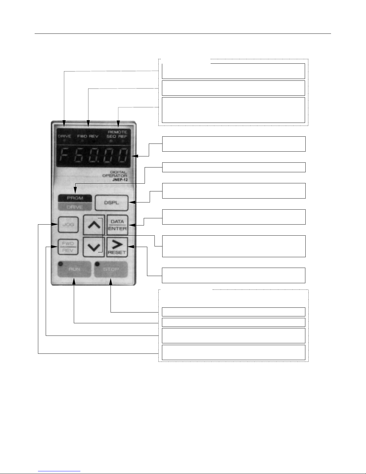
1.2 DIGITAL OPERATOR KEYPAD
Mode Display
Drive Mode Display
Red lamp lights in DRIVE mode and goes out in PRGM mode.
Rotation Direction Display
Red lamp lights in DRIVE mode and goes out in PRGM mode.
REMOTE Mode
Red lamp lights when controlled by external terminal commands.
SEQ: When RUN/STOP signal is selected from terminals.
REF: When fre
Displa
Displays set value of each function or monitoring values such as
frequency and output current. (5 digits)
uency reference is selected from terminals.
Mode Selection Ke
Depressing this key changes mode. (DRIVE or PRGM)
Display Selection Ke
Depressing this key changes the display.
Read/Write Ke
Depressing this key recalls and displays data from memory.
Depressing it a second time enters display data into memory.
Numeral Change Key
Changes numeral such as set values and constant signals.
︿
: Increment key
﹀
: Decrement key
Digit Selection Ke
Selects numerical digits. Selected digit blinks.
This key resets operation when fault occurs.
Run Command Ke
Run Command Key to operate by digital operator.
STOP command is input. (Motor stops in either mode.)*
Red lamp lights by depressing STOP. *
Selects FWD or REV run.
Effective only in DRIVE mode.
While depressing this key, JOG speed is selected.
Effective only in DRIVE mode.
─6─
Page 7
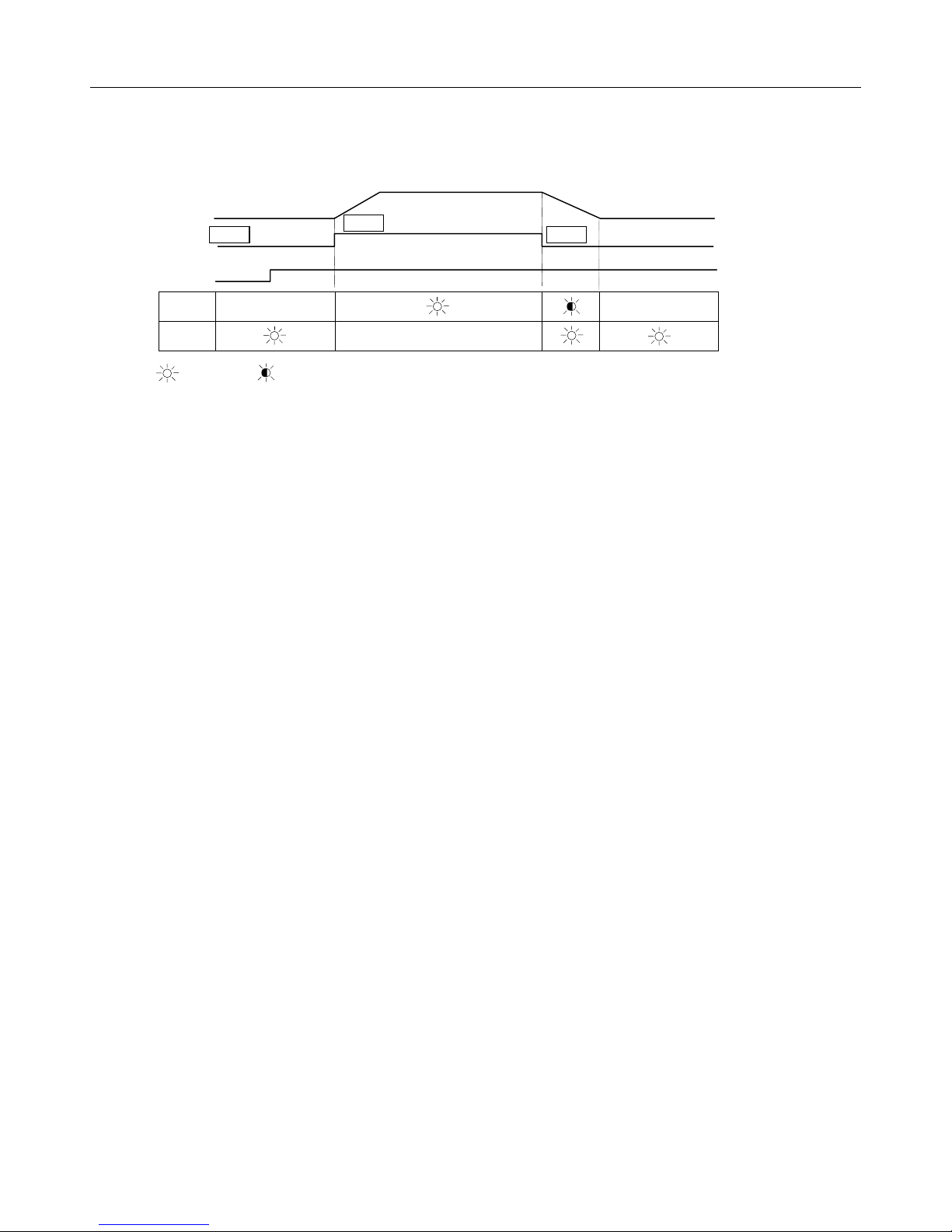
*
RUN or STOP lamp changes in accordance with the following operations.
INVERTER
OUTPUT
FREQUENCY
RUN
FREQUENCY
RUN
Lamp
STOP
Lamp
: Lit : Blink
●
●
: Off
STOP
●
●
─7─
Page 8
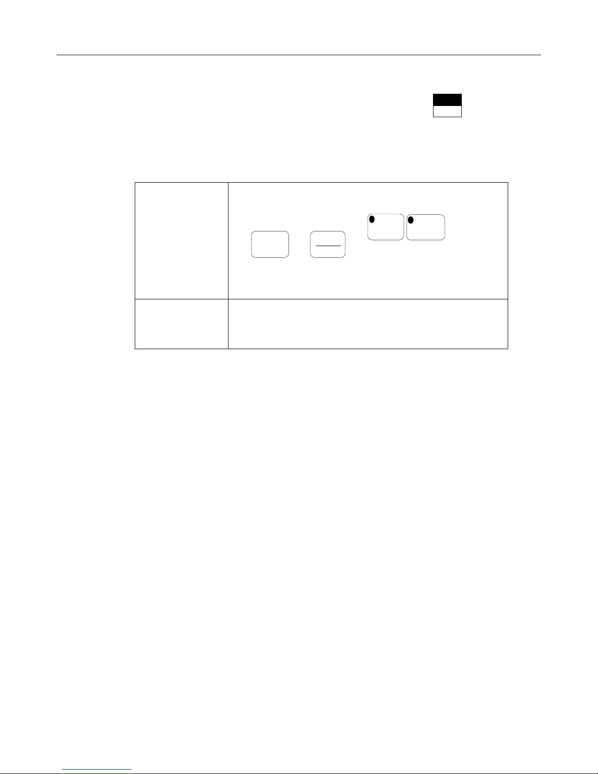
2. DRIVE MODE AND PRGM (PROGRAM) MODE
Selection of DRIVE mode or PRGM mode can be performed by using the key when the
PRGM
DRIVE
inverter is stopped. When function selection or a change of set value is required, switch to the PRGM
mode.
Operation is enabled.
An operation can be performed by
DRIVE mode functions
PRGM mode functions
JOG
and keys.
Frequency reference value or bn constants
can be changed while running.
Program (function selection, constant setting) can be changed.
Note: Cannot be performed while running.
FWD
REV
RUN
STOP
─8─
Page 9
*
g
y
y
y
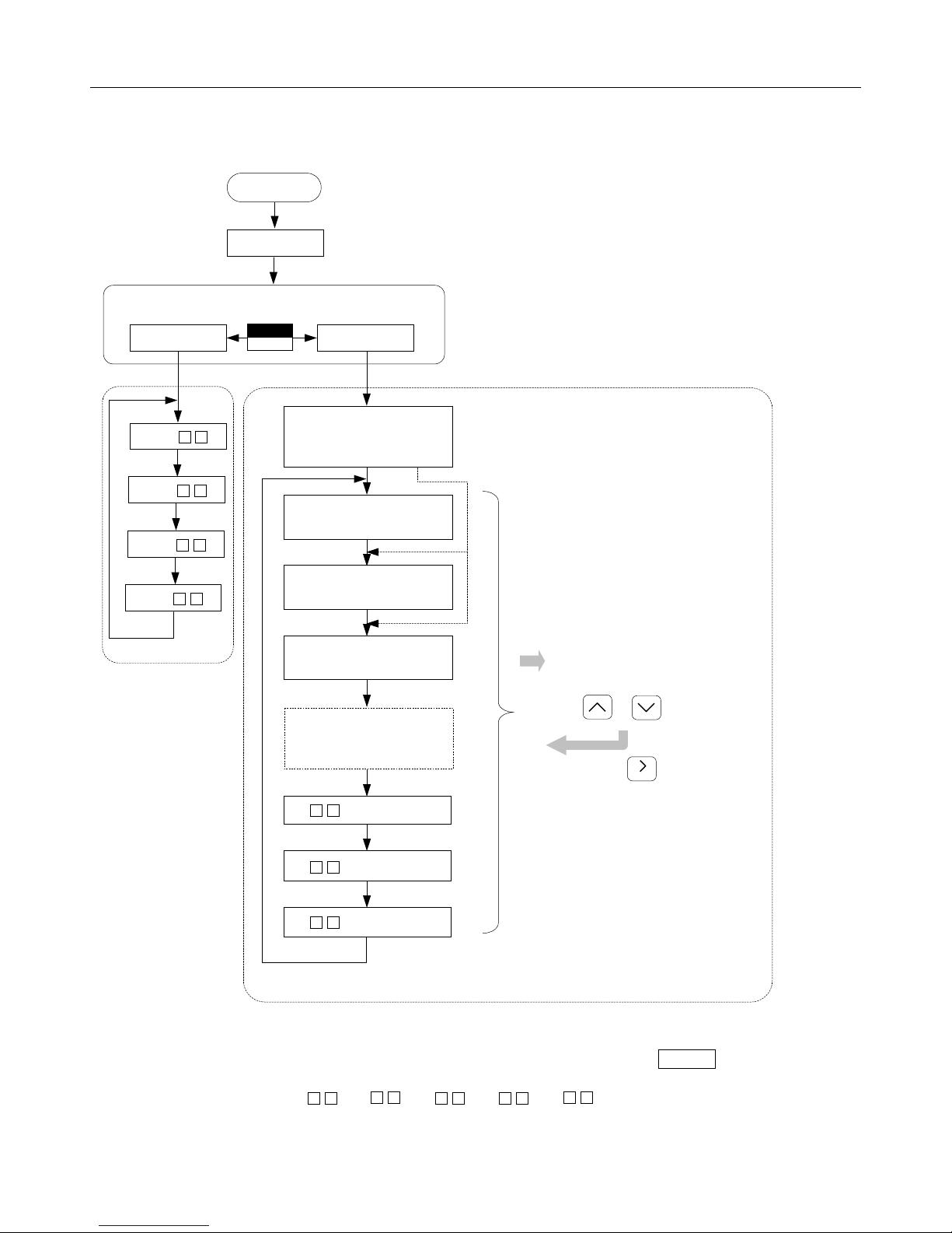
2.1 DISPLAY CONTENTS
MODE SWITCHABLE ONLY AT STOPPING
PRGM
DRIVE
É
-
Display of faults which
occurred before power
supply was turned OFF
É
É
É
Frequency reference
value displa
-
Output frequency
-
monitor displa
Output current monitor
displa
Display of faults which
occurred before power
supply was turned OFF
If a fault occurs, the contents
are displayed.
Fault occurrence order and
display are provided by
Fault reset
or keys.
RESET
Un- monitor É display
É
An- reading/setting
É
bn- readin
/setting
*The constant group to be displayed is changed each time display selection key DSPL is depressed.
ÉFor details of constants ( An- , bn- , Cn- , Sn- , Un- , refer to Section 7,
“CONSTANTS/FUNCTION LIST.”
─9─
Page 10

2.2 CONSTANT GROUPS
Constants of GA7200 are classified as follows:
Constant Group Contents
An-
bn-
Cn-
Sn-
Frequency reference setting
Constant group able to be changed while running
Constant, among control constant groups, related to operation
change characteristics
Constant, among system constant groups, to be used for
function selection
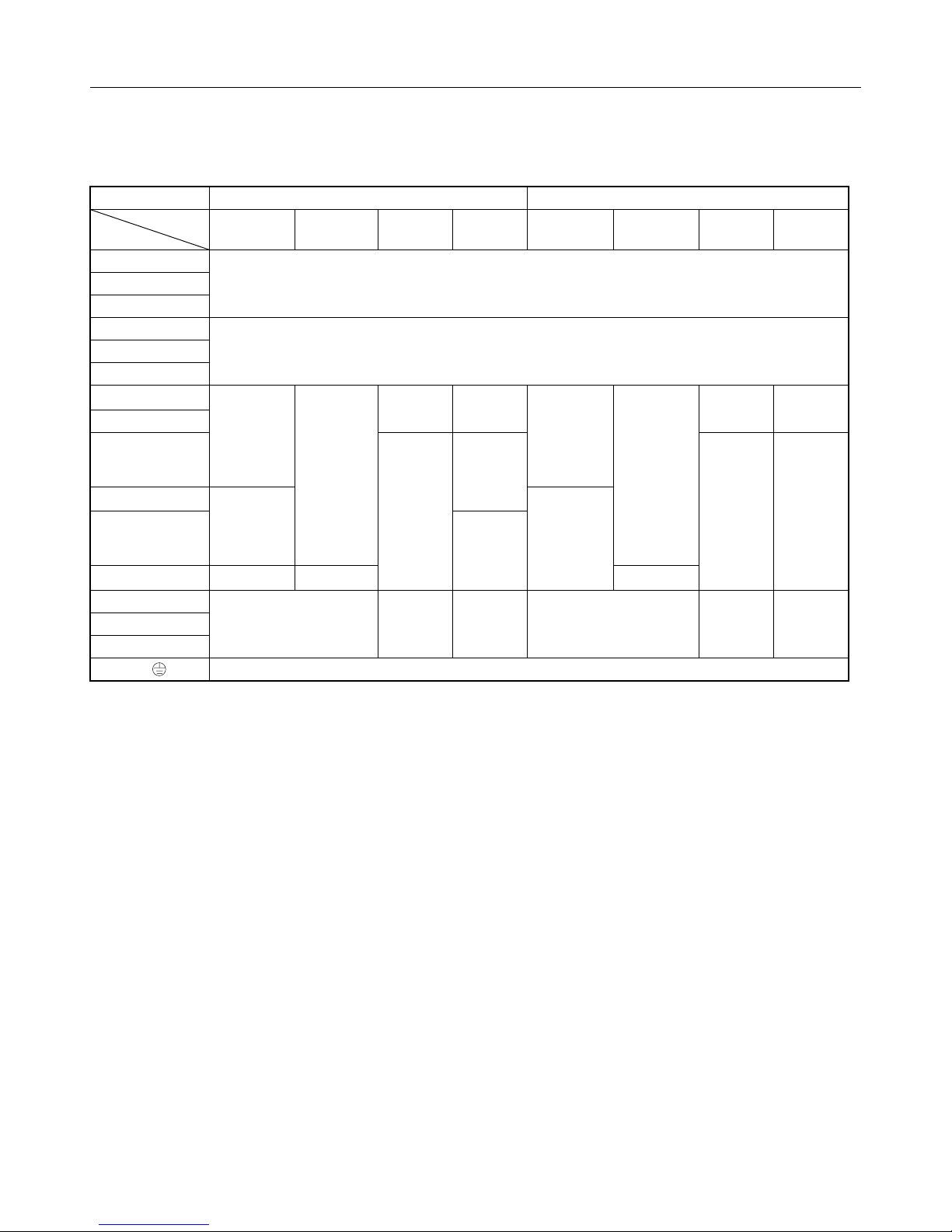
The ability to set or read the different groups of constants is
determined by Sn-03 as shown below.
DRIVE Mode PRGM Mode
Sn-03
Setting Reading Setting Reading
0000
0101 An bn, Sn, Cn An bn, Sn, Cn *
An, bn Sn, Cn An, bn, Sn, Cn … Factory set
Remarks
* It is recommended that Sn-03 be set to 0101 and reading mode entered after test run adjustment.
Note: To read the Sn or Cn constants while in the DRIVE mode, depress the
key depressed.
RESET
DSPL
key with
─10─
Page 11
3. CONSTANTS SETTING AND CHANGE
3.1 STANDARD FACTORY SETTING
Contents Set Value
Frequency Reference Input Can be set by digital operator.
Run Command Input
V/f Pattern 60Hz, constant torque characteristics (Standard motor)
Acceleration Time 10 seconds
Motor Protection Electronic overload thermal protection (Standard motor)
Can be set by digital operator.
(RUN/STOP/FWD/REV/JOG)
Note: For more details, refer to Section 7 “CONSTANTS/FUNCTION LIST.”
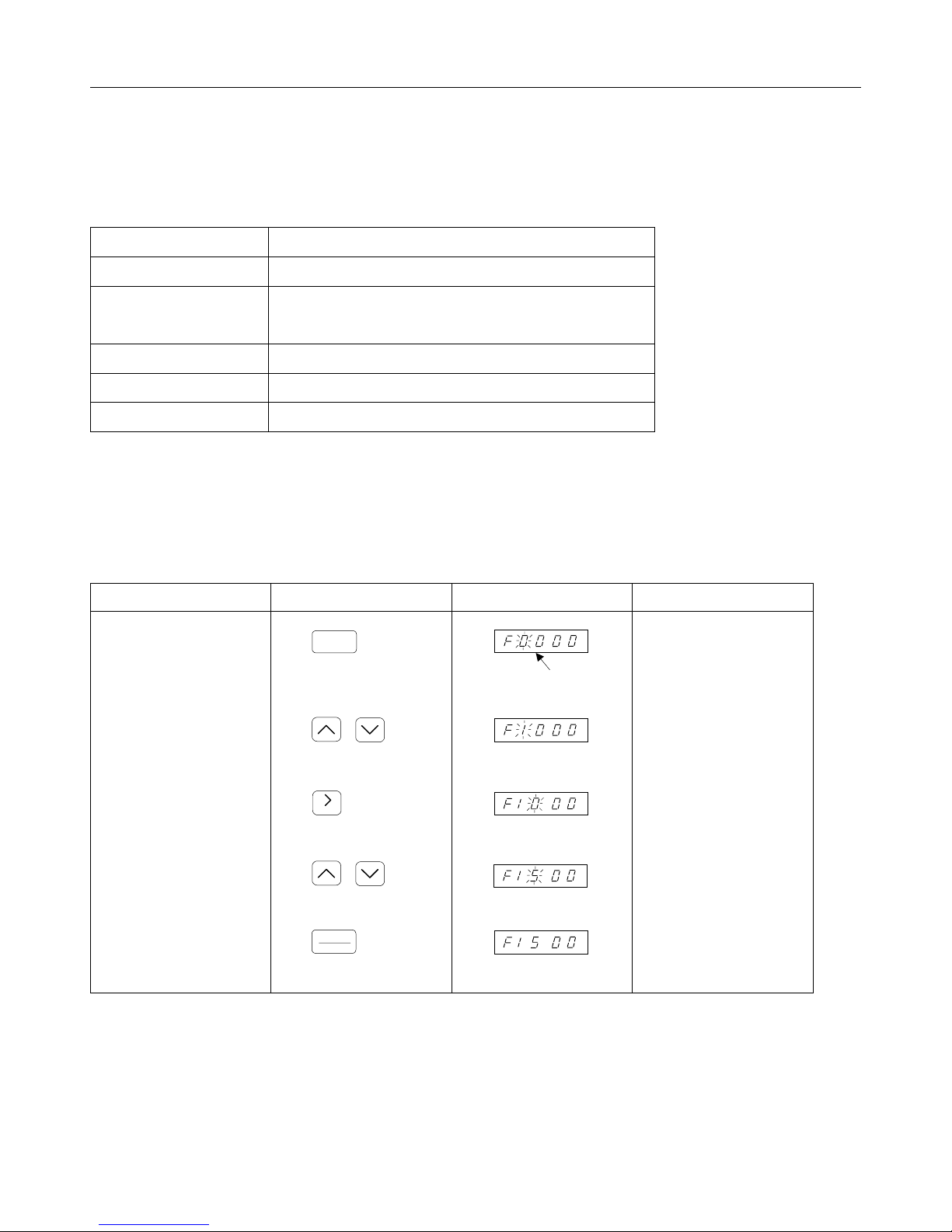
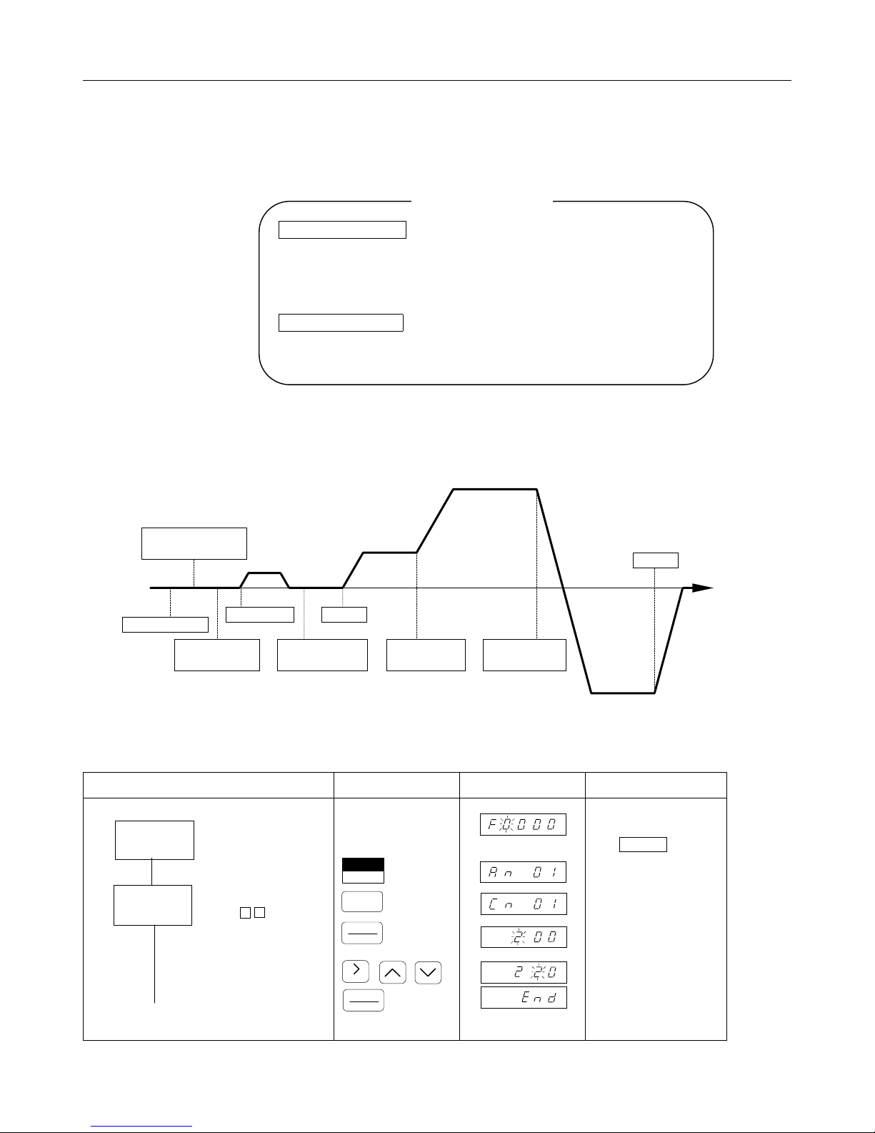
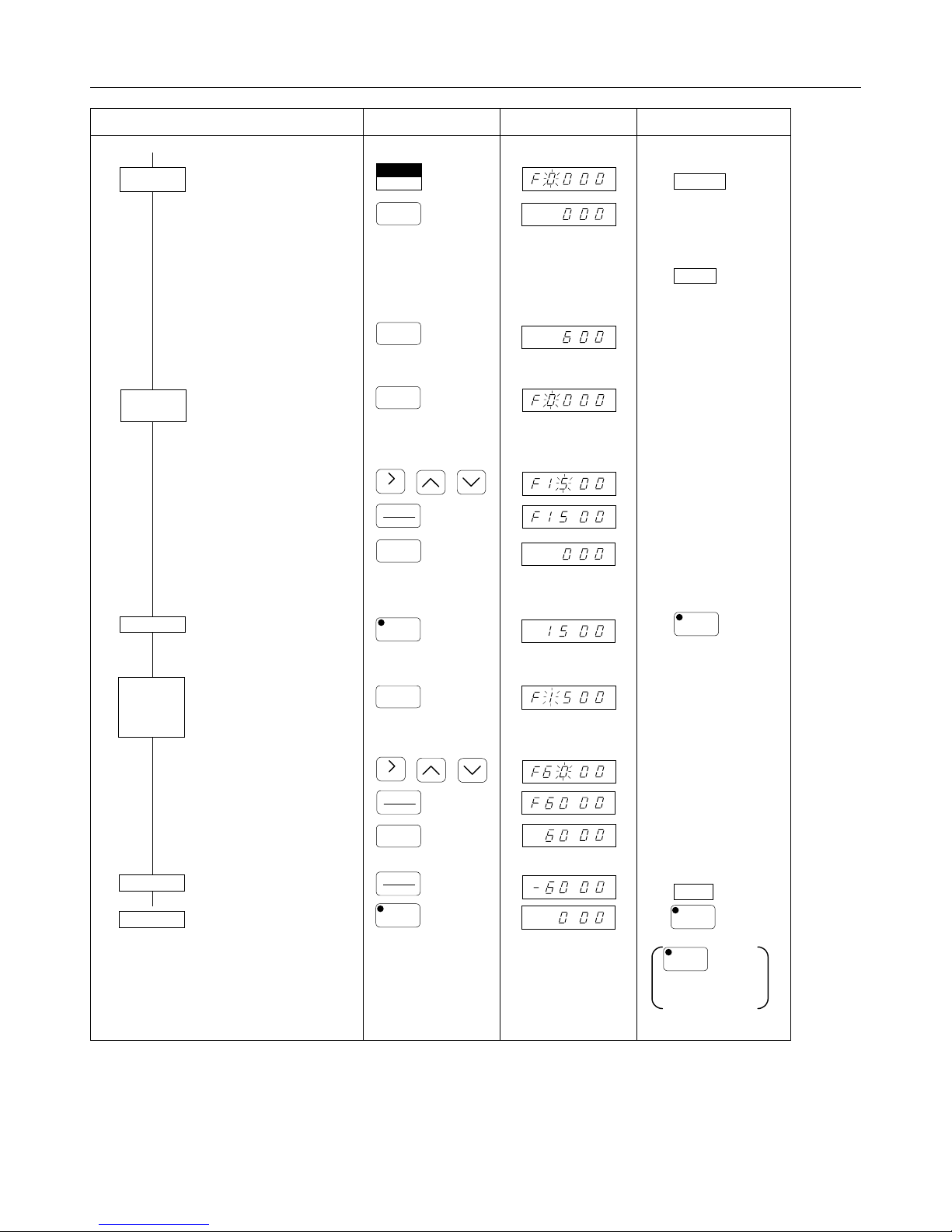
3.2 FREQUENCY REFERENCE SETTING AND CHANGE
(Example) Frequency reference value is set to 15Hz.
Description Keypad Operation Digital Operator Display Remarks
•
Frequency reference value
is displayed.
•
Set or change reference
value. (Input “1”).
DSPL
Blinking
•
Select digit.
•
Set or change reference
value. (Input “5”.)
•
Write-in constant.
RESET
ENTER
DATA
─11─
Stops blinking for 2 seconds.
Page 12

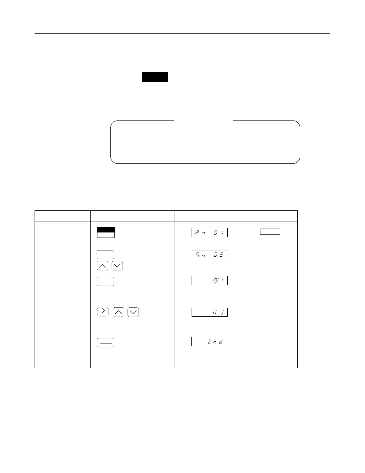
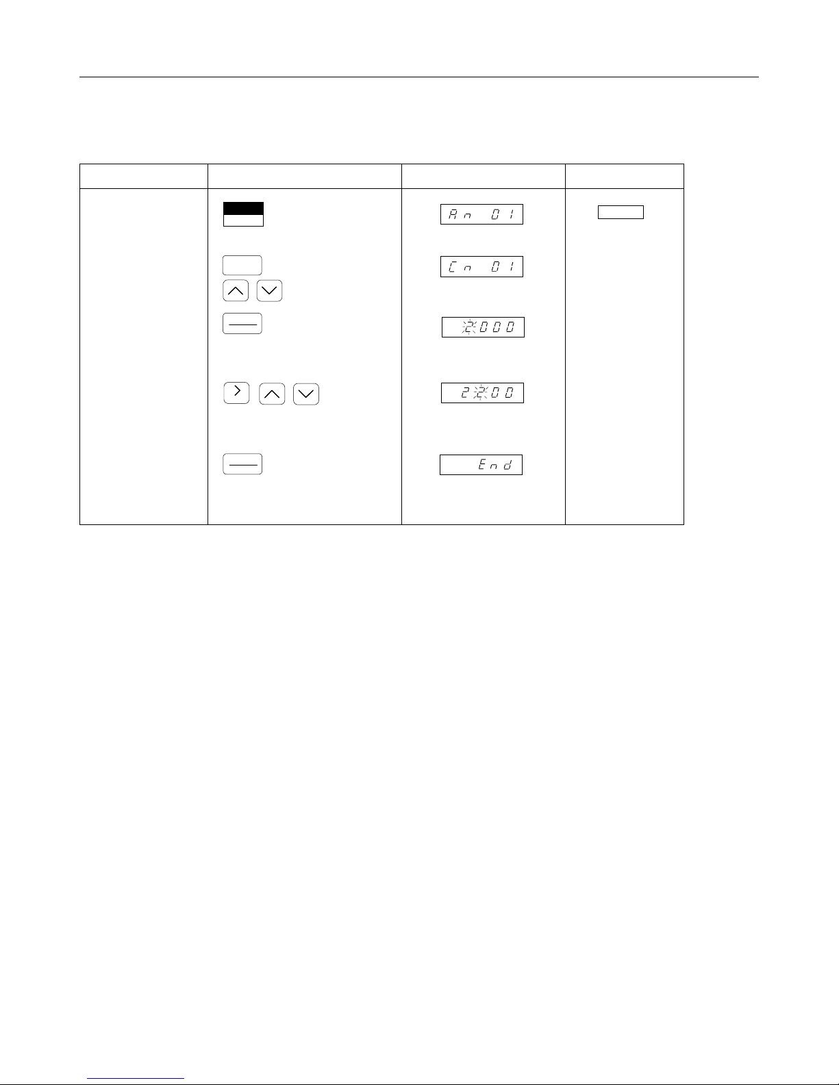
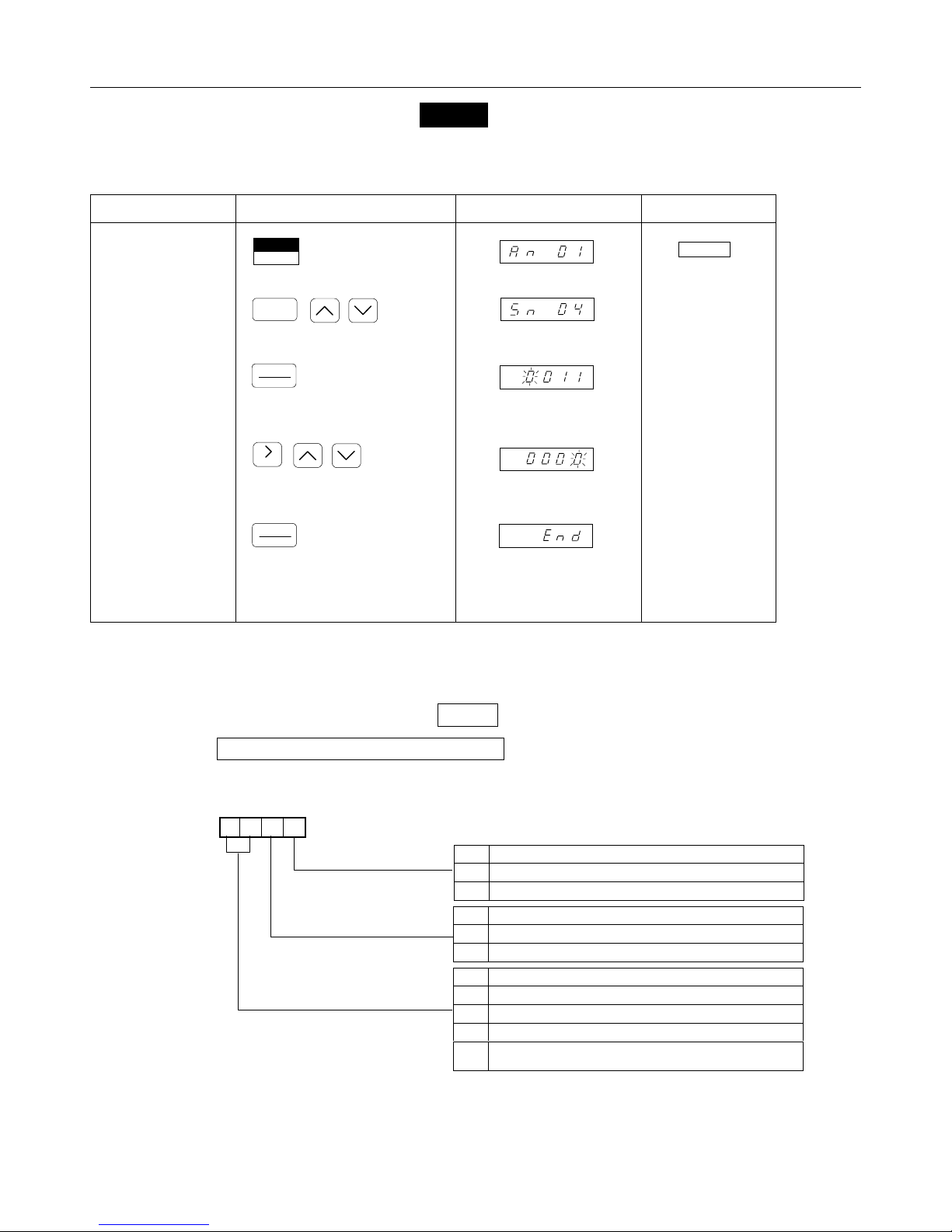
3.3 CONSTANTS CHANGE AND FUNCTION SELECTION
All constants are changed and functions are selected in the same manner.
When changing Cn- and Sn- constants, program mode must be selected.
(Example) Jog frequency (An-09) set value is changed from 6Hz to 10Hz.
Description Keypad Operation Digital Operator Display Remarks
•
Constant group to be set
or changed is displayed.
•
Select constant No. to be
set or changed.
•
Constant set value is
displayed.
•
Constant is set or
changed.
•
Set value is written in.
DSPL
DATA
ENTER
DATA
ENTER
-
-
(“End” is displayed for 0.5
second).
Confirm “End” displayed for
each constant.
─12─
Page 13
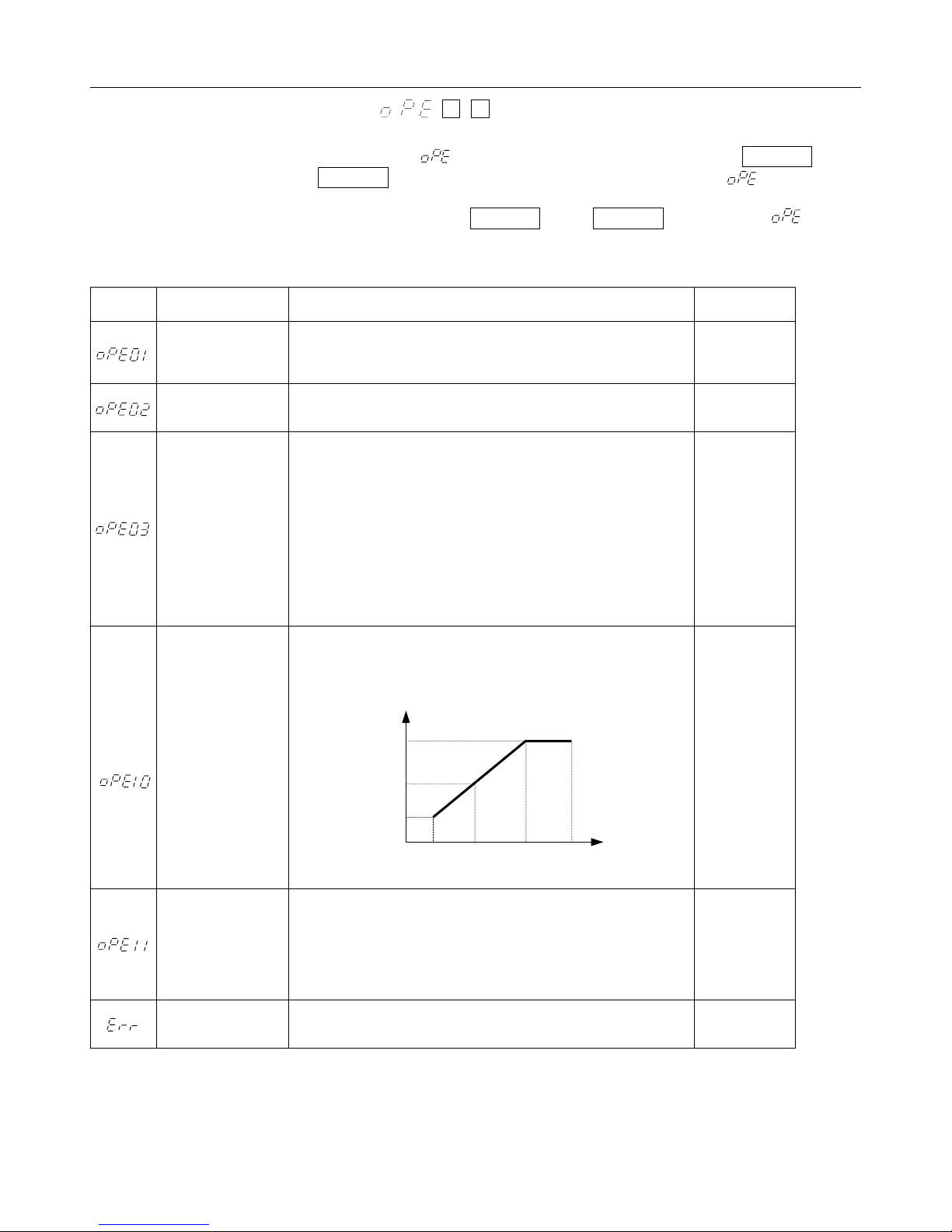
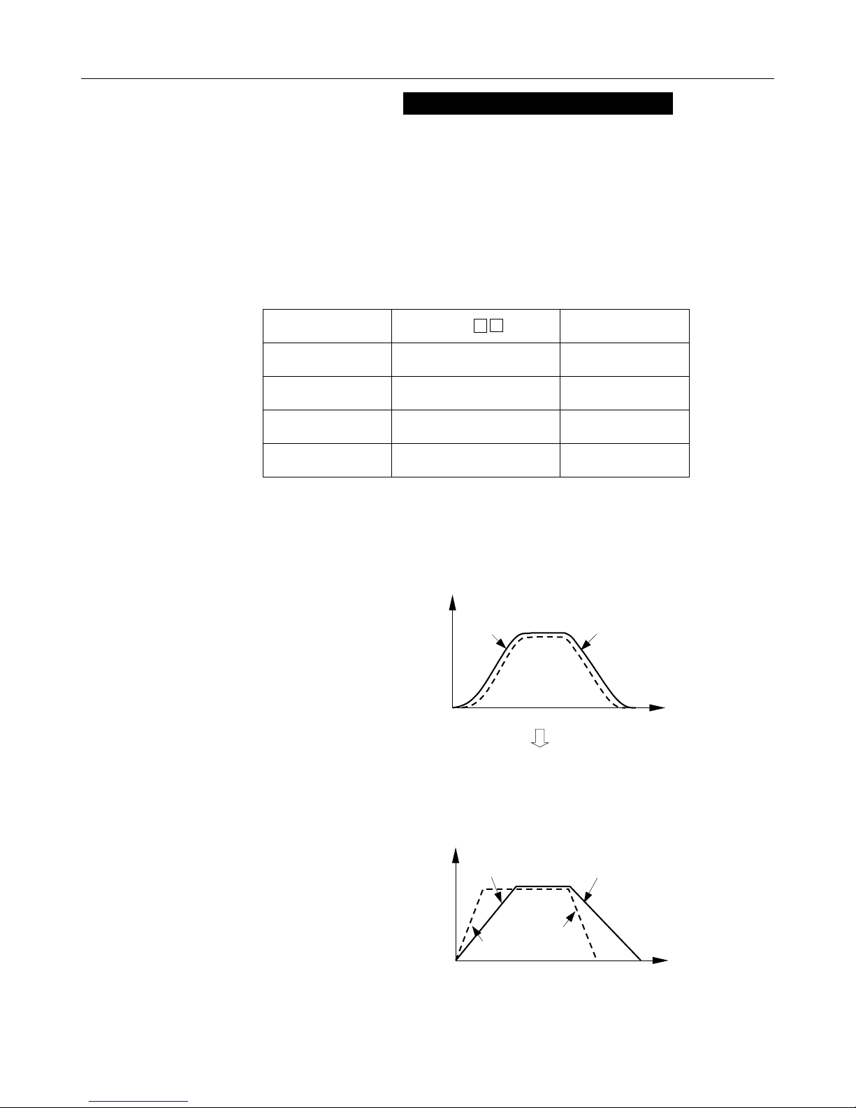
3.4 OPERATION ERRORS “ “
The constant setting fault is checked when power is applied or PRGM is
changed to DRIVE mode. Digital operator displays faults if the is detected.
The fault contact output of the inverter is not executed. If the following “conditions”
occur at power ON or changing PRGM into DRIVE , it becomes .
Display Fault Conditions Example
kVA Constant
Setting Fault
(Sn-01)
Constant Setting
Range Fault
Multi-function Input
Setting Fault (Sn-15
to-18)
V/f Data Set Fault
(Cn-02 to-08)
When 460V class constant is set for 230V class inverter or 230V
class constant is set for 460V.
When “out of setting range” constant is set.
When multi-function inputs Sn-15 to -18 are set as follows:
Set values are not arranged in numerical order. (including equal
values)
Both search references “61” and “62” are set.
Up command (set value = 10) and DOWN command (set value =
11) cannot be set simultaneously.
Up command (set value = 10), DOWN command (set value = 11)
and accel prohibit command (set value = 0A) are set together.
More than two set values except FF are set.
When Cn-02 to 08 do not satisfy the following conditions.
F
max.≧FA>FB≧FMIN.
(Cn-02) (Cn-04) (Cn-05) (Cn-07)
V
V
max.
(Cn-03)
V
C.
(Cn-06)
V
min.
(Cn-08)
F
(Cn-07)
min.
F
(Cn-05)
Sn-15 = 3
Sn-16 = 4
Sn-17 = 6
Sn-18 = 5
Cn-02 = 50
Cn-04 = 60
Cn-05 = 3
Cn-07 = 1.5
F
F
A
B
(Cn-04)
max.
(Cn-02)
F
Constant Set Fault
Constant Write-in
Fault
When any following set fault:
Carrier frequency upper limit (Cn-23) > 5kHz and Carrier frequency
lower limit (Cn-24) ≦ 5kHz.
Carrier frequency proportional Gain
(Cn-25) > 6 and (Cn-23) < (Cn-24)
The constant is not written in correctly to NV-RAM.
(Only at initialization)
─13─
Cn-23 = 6kHz
Cn-24 = 5kHz
Page 14
/
/
/
/
/
/
4. WIRING
GA7200 has been programmed to operate from the digital operator when shipped from the factory.
Therefore, just connecting the main circuit power enables drive operation.
Note: When external signals or external devices and digital operator are used, refer to Section 7,
“CONSTANTS/FUNCTION LIST”, in this manual.
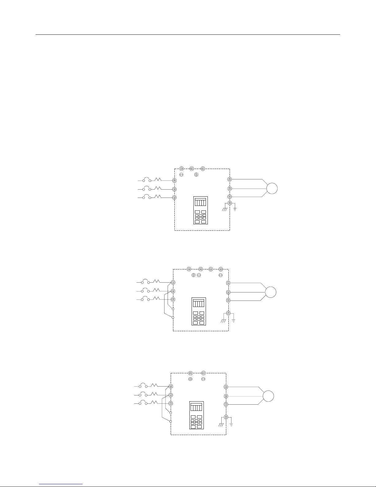
4.1 CONNECTION DIAGRAM
230V Class
10 HP (7.5kW, 13.7kVA) or smaller
B1/
3-PHASE
POWER
SUPPLY
R
S
T
15/20 HP (11/15kW, 20.6/27.4kVA)
3-PHASE
POWER
SUPPLY
R
/L1
S
/L2
T
/L3
r
s
25 HP (18.5kW, 34kVA) or larger
/L1
GA7200
/L2
/L3
JNEP--12
B1/ 2
GA7200
JNEP--12
B2
B2
T3/W
T1
T2
T3
T1/U
T2/V
PE
PE
U
V
W
IM
IM
3-PHASE
POWER
SUPPLY
R
/L1
/L2
S
/L3
T
r
s
─14─
GA7200
JNEP--12
T1
T2
T3
PE
U
V
W
IM
Page 15
/
/
/
/
/
/
/
/
/
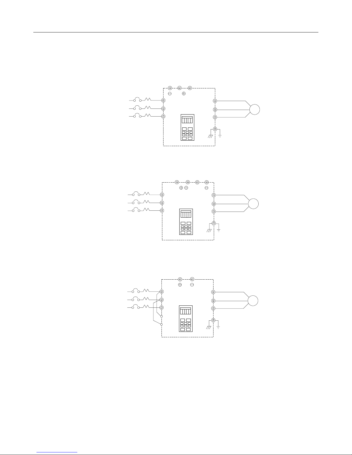
460V Class
10 HP (7.5kW, 13.7kVA) or smaller
3-PHASE
POWER
SUPPLY
15/20 HP (11/15kW, 20.6/27.4kVA)
3-PHASE
POWER
SUPPLY
25 HP (18.5kW, 34kVA) or larger
3-PHASE
POWER
SUPPLY
/L1
R
/L2
S
/L3
T
/L1
R
/L2
S
/L3
T
R
/L1
/L2
S
/L3
T
r
S400
B1/
GA7200
B1/
GA7200
JNEP--12
GA7200
JNEP--12
B2
JNEP--12
U
T1
T2
V
T3
W
PE
2
B2
U
T1
T2
V
T3
W
PE
U
T1
T2
V
T3
W
PE
IM
IM
IM
─15─
Page 16
4.2 TERMINAL FUNCTIONS
MAIN CIRCUIT
VOLTAGE 230V CLASS 460V CLASS
Rating
Terminal
R(L1)
S(L2)
T(L3)
U(T1)
V(T2)
W(T3)
B1/○+
B2
○
-
○
+1, ○+
○
+2
○
+3
s
r
s400
PE ( ) Grounding
1~10HP 15~20HP 25~30HP 40~100HP 1~10HP 15~20HP 25~60HP 75~450HP
Circuit input power supply
Inverter output
B1/○+,B2:
braking
resistor
B1/○+,○-:
DC power
supply
-
- -
B2:
braking
resistor
○
+
2:optional
DCL
DC power
supply
-
B1/○+,
B1/○+,
B1/○+,○-:
- - - -
+1,
+2,○+
○
+, ○- : DC
power
supply or
Braking Unit
-
r-s:
cooling
fan power
supply
○
○
- : DC
power
supply or
Braking
Unit
○
3:
DCL
r-s:
cooling
fan power
supply
B1/○+,B2:
braking
resistor
DC power
B1/○+,○-:
supply
-
B1/○+,B2:
braking
resistor
B1/○+,○+
2:optional
DCL
B1/○+,○-:
DC power
supply
-
-
○
○
- : DC
power
supply or
Braking
Unit
○
3:
DCL
r-s:
cooling
fan power
supply
+1,
+2,○+
○
+, ○-:
DC power
supply or
Braking
Unit
r-s:
cooling
fan power
supply
─16─
Page 17

CONTROL CIRCUIT
Classifi-
cation
Sequence Output Signal
Analog Input Signal
Sequence Output Signal
Output
Signal
Terminal Signal Function Description Signal Level
Forward operation-stop
1
signal
Reverse operation-stop
2
signal
3 External fault input Fault at closed, normal state at open
4 Fault reset input Reset at closed
Master/Aux.
5
Multi-step speed ref. 1
6 Multi-step speed ref. 2 Effective at “closed”
7 Jog command Jog run at “closed”
8 External coast to stop
11 Sequence common -
Power supply terminal for
15
speed reference
13 0 to +10V/100% freq. 0 to +10V (20kΩ)
Master speed frequency
reference
14
16 Aux. frequency reference 0-10V/100%
Common terminal for control
17
circuit
12 Shield connection - -
9
During running (NO) Run at “closed”
10
25 Zero speed detection
26 Speed agreed detection
27 Open collector output common -
18
Fault contact output
19
common (NO, NC)
20
21 Frequency meter output Analog
22 Common
Forward run at closed, stop at open
Reverse run at closed, stop at open
Auxiliary freq. ref. at
“closed”
Inv. output stop at
“closed”
Speed reference power supply
4 to 20mA/100% freq. 4 to 20mA (250Ω)
0 -
Occurs at minimum
freq. (Cn-07) or less
Occurs when the
frequency reaches
1% of set freq.
Fault at closed between terminals 18 and 20
Fault at open between terminals 19 and 20
0 to 10V/100% freq.
Multi-function contact input:
the following signals are
available to select.
Forward/reverse select, run
mode select, multi-speed
select, jog frequency select,
accel/decel time select,
external fault, external base
clock stop, hold command,
aux. input effective, speed
search, energy-saving
operation.
Multi-function contact input:
one of the following signals
are available to select. Speed
command, speed gain, speed
bias, over torque, over voltage
bias, rate of accel/decel, DB
current.
Multi-function contact input:
one of the following signals
available to output. Output
during running, zero speed,
synchronized speed, arbitrary
speed agreed, frequency
detection, overtorque,
±
undervoltage, run mode,
coast to stop, braking resistor
overheat..
Ammeter/voltmeter/wattmeter
output selection available
Photo-coupler insulation
input +24V DC 8mA
+15V (Allowable current
20mA max.)
0 to +10V (10kΩ)
Dry contact
Contact capacity:
250V AC 1A or less
30VDC 1A or less
Open collector output
+48V 50mA or less
Dry contact
Contact capacity:
250VAC 1A or less
30VDC 1A or less
0 to11V max.
2mA or less
─17─
Page 18
,
supply
5. DIGITAL OPERATOR PROGRAMMING
The following is an operation example for the digital operator keypad.
Operation Pattern
Typical Operation
INPUT VOLTAGE
SETTING
POWER ON
FWD
SELECTION
Description Keypad Operation Digital Operator Display Remarks
PRECAUTION
Before Power ON
For the 460V class, 25HP (18.5kW, 34kVA) or larger inverter,
change the supply voltage selection tap of control transformer
to the same tap as input voltage. Refer to Installation Manual.
Before Operation
Be sure to set input voltage in control constant Cn-01.
The initial value is 220 for 230V class
FWD 60Hz
FWD 15Hz
RUN FWD JOG
FREQUENCY
SETTING
SET VALUE
CHANGE
REV
SELECTION
440 for 460V class.
REV 60Hz
t
•
Frequency reference
1
Turn on
○
power supply
Set input
2
○
voltage power
Cont’d
value is displayed.
•
Select PRGM mode.
•
Select control constant
(Cn- )
(ex: 220V)
•
Display Cn-01 data.
•
Set 220V as input
voltage.
PRGM
DRIVE
DSPL
DATA
ENTER
RESET
DATA
ENTER
Depress
three times.
─18─
-
-
LED DRIVE OFF
Displayed for 0.5 second.
Confirm the display.
Page 19
g
3
○
4
○
Cont’d
FWD JOG
Frequency
Settin
Description Keypad Operation Digital Operator Display Remarks
15Hz
• Select DRIVE mode.
• Select output frequency
monitor display.
• Select rotating direction.
(FWD is default at power
ON.)
• Jog operation.
• Frequency reference
value display is selected.
• Change reference value.
• Set value is written in.
• Select output frequency
monitor display.
PRGM
DRIVE
DSPL
JOG
DSPL
RESET
DATA
ENTER
DSPL
Depress
Six times.
LED DRIVE lights.
LED FWD lights.
Stops blinking for two
seconds.
5
○
FWD RUN
6
○
frequency
7
○
REV RUN
8
○
Change
reference
value
60Hz
STOP
• Running operation.
• Select frequency
reference value display.
• Change reference value.
• Set value is written in.
• Select output frequency
monitor value.
• Switch to reverse run.
• Decelerate to a stop.
RUN
DSPL
RESET
DATA
ENTER
DSPL
FWD
REV
STOP
LED lights.
RUN
Stops blinking for two
seconds.
LED REV lights.
STOP
LED lights.
blinks
RUN
while decelerating
─19─
Page 20
pag
6. PROGRAM MODE SETTING AND CHANGE
The following shows an example of main functions and characteristics.
6.1 V/f PATTERN SETTING
Sn-02
16 types of V/f patterns are available according to motor type, load characteristics and operating
conditions.
To select V/f pattern, set the inverter input voltage to Cn-01.
For details on the different V/f patterns, refer to Par. 7.3
SYSTEM CONSTANTS “V/f PATTERN SELECTION” on
e 67.
PRECAUTION
■■ FIXED V/f PATTERN SELECTION
(Example) Change to variable torque characteristics (Set “7”.)
Description Keypad Operation Digital Operator Display Remarks
• Select PRGM mode.
• Select Sn-02.
• Constant display
value is displayed.
• Set or change
constant.
• Constant value is
written in.
PRGM
DRIVE
DSPL
DATA
ENTER
RESET
DATA
ENTER
Depress twice.
-
-
LED DRIVE OFF
Displayed for 0.5
second. Confirm the
display for each
constant.
─20─
Page 21
■ INPUT VOLTAGE SETTING
(Example) Set input voltage to 220V.
Description Keypad Operation Digital Operator Display Remarks
• Select PRGM mode.
• Select Cn-01.
• Constant set value
is displayed.
• Set or change
constant.
• Constant value is
written in.
PRGM
DRIVE
Depress three times.
DSPL
DATA
DATA
ENTER
RESET
ENTER
-
-
LED DRIVE OFF
Displayed for 0.5
second. Confirm the
display for each
constant.
─21─
Page 22
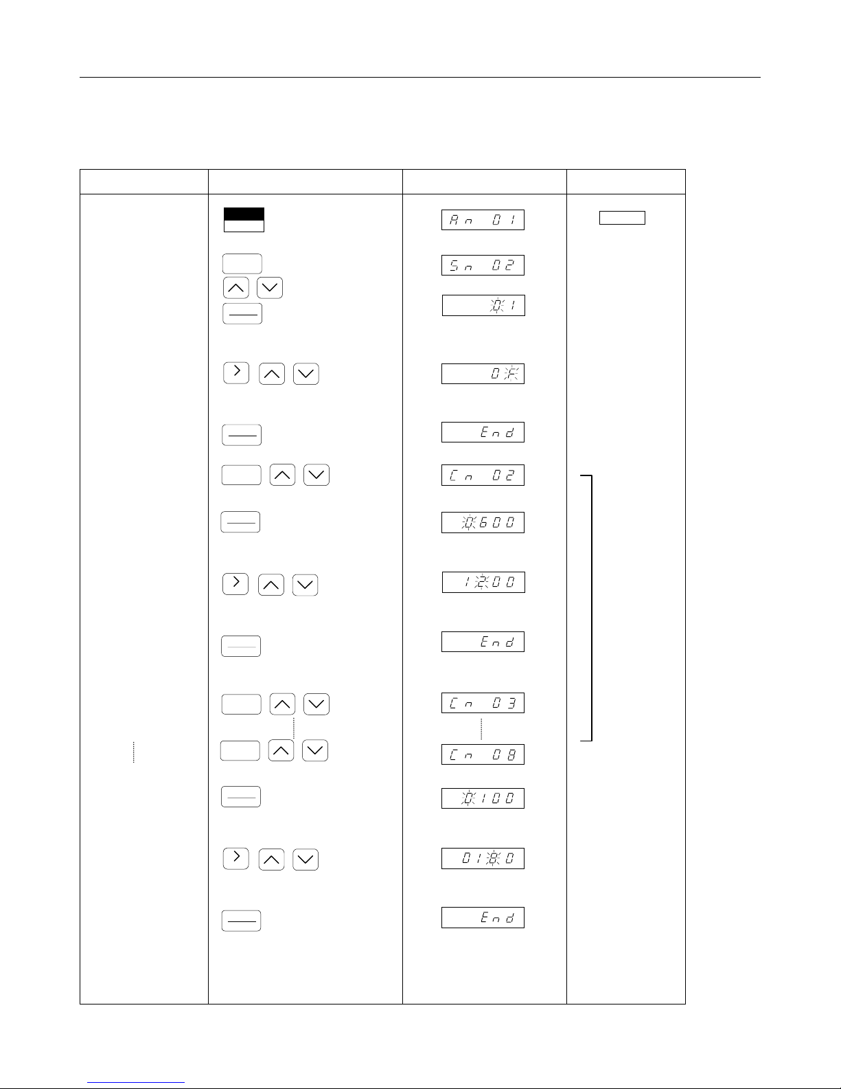
■ ARBITRARY V/f SETTING (Sn-02, Cn-02 to -08)
(Example) Change to “F
= 120Hz, V
max
= 18V”.
min
Description Keypad Operation Digital Operator Display Remarks
• Select PRGM mode.
• Select Sn-02.
• Constant set value
is displayed.
• Set or change
constant. Set to “F”.
• Constant is written
in.
• Select Cn-02.
• Constant set value
is displayed.
• Set or change
constant.
• Constant value is
written in.
• Select Cn-02.
• Select Cn-08
• Constant set value
is displayed.
• Set or change
constant.
• Constant value is
written in.
PRGM
DRIVE
DSPL
DATA
ENTER
RESET
DATA
ENTER
DSPL
DATA
ENTER
RESET
DATA
ENTER
DSPL
DSPL
DATA
ENTER
RESET
DATA
ENTER
Depress twice.
-
-
-
-
-
LED DRIVE OFF
Refer to the
next page
Displayed for 0.5
second. Confirm the
display for each
constant.
─22─
Page 23

Set Sn-02 to F.
(18V) (Cn-08)
V
V
max.
(Cn-03)
V
C.
(Cn-06)
V
min.
F
(Cn-07)
min.
(Cn-05)
F
B
F
A
(Cn-04)
F
max.
(Cn-02)
(120Hz)
F
If F
MAX.
≧
F
>FB≧F
A
is not satisfied, a setting error occurs.
MIN.
When V/f pattern is selected to be linear, set the same value for Cn-07 and
Cn-05. (Cn-06 setting is disregarded). Refer to pages 67, 68 and 69 for V/f
pattern selection.
─23─
Page 24
(
6.2 ACCEL/DECEL TIME SETTING
bn-01 to -04 (Sn-06, Sn-15 to -18)
Accel/decel time can be changed in DRIVE mode during running.
• Acceleration and deceleration time each has two set values. When “ accel/decel time
change” is selected (7 is set in Sn-15, Sn-16, Sn-17 or Sn-18) as a multi-function terminal
function, the values set in bn-03 and-04 become effective.
• S-curve characteristics of soft start can be selected in the 1-and 2-digits of Sn-06.
(Example) When S-curve not used, accel and decel times are set with
bn-01 through bn-04.
bn- Set Value
Accel Time 1 (bn-01) 5 seconds
Decel Time 1 (bn-02) 8 seconds
Accel Time 2 (bn-03) 3 seconds
Decel Time 2 (bn-04) 3 seconds
Factory setting
(S-curve characteristics: provided)
bn-01 to 04: 10 seconds
Fref.
bn-01, 03
bn-02, 04
0
t
Setting change
(S-curve characteristics: not provided)
Fref.
bn-01
5 sec.)
bn-03
bn-02 (8 sec.)
bn-04
t
─24─
Page 25
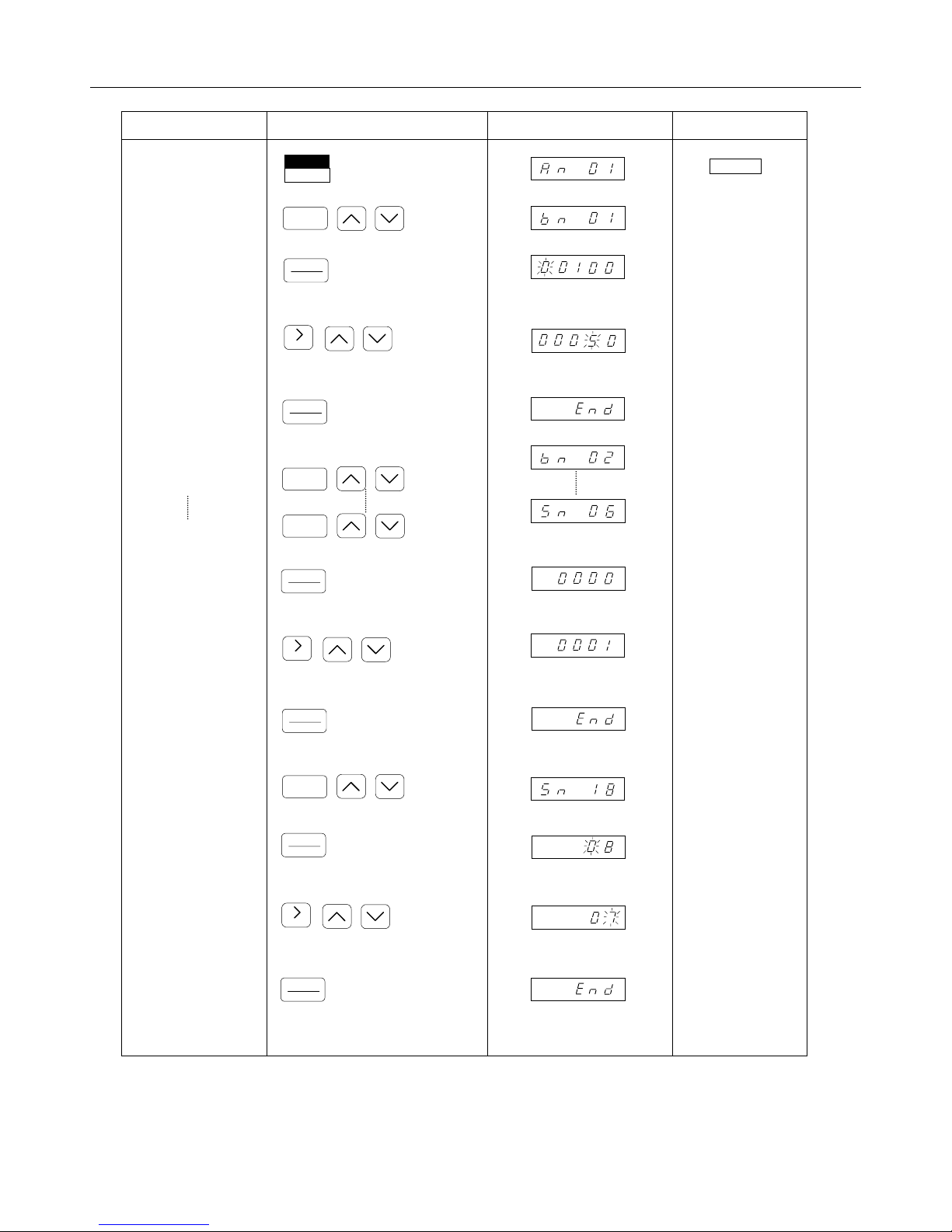
Description Keypad Operation Digital Operator Display Remarks
•
Select PRGM mode.
•
Select bn-01.
•
Constant set value
is displayed.
PRGM
DRIVE
DSPL
DATA
ENTER
-
-
LED DRIVE OFF
•
Set or change
constant.
•
Constant value is
written in.
•
Select bn-02.
•
Select Sn-06.
•
Constant set value
is displayed.
•
Set or change
constant.
•
Constant value is
written in.
•
Select Sn-18.
RESET
DATA
ENTER
DSPL
DSPL
DATA
ENTER
RESET
DATA
ENTER
DSPL
-
-
-
Displayed for 0.5
second. Confirm the
display for each
constant.
Refer to the
next page
Displayed for 0.5
second. Confirm the
display for each
constant.
•
Constant set value
is displayed.
•
Set or change
constant.
•
Constant value is
written in.
DATA
ENTER
RESET
DATA
ENTER
─25─
Displayed for 0.5
second. Confirm the
display for each
constant.
Page 26

6.2 ACCEL/DECEL TIME SETTING
* Input signal selection
Sn-06 Operation mode selection 3
4 3 2 1
DIGIT
Machine requires soft start at acceleration and soft stop at
deceleration.
bn-01 to -04 (Sn-06, Sn-15 to -18)
Soft start S-curve characteristics
00 S-curve 0.2 sec.
10 S-curve 0.5 sec.
11 S-curve 1.0 sec.
Master speed frequency reference
0 Normal characteristics
1 Reverse characteristics
Processing when frequency reference is missing
0 Stop by reference input
1 Operation to continue with 80% of frequency reference
Application Example
(Cont’d)
─26─
Page 27
6.3 INPUT SIGNAL SELECTION
Sn-04
(Example) Change from operator control to terminal control of run/stop and frequency reference.
Description Keypad Operation Digital Operator Display Remarks
•
Select PRGM mode.
•
Select Sn-04.
•
Constant display
value is displayed.
•
Set or change
constant.
•
Constant value is
written in.
PRGM
DRIVE
DSPL
DATA
ENTER
RESET
DATA
ENTER
-
-
LED DRIVE OFF
Refer to the
diagram shown
below.
Displayed for 0.5
second. Confirm the
display for each
constant.
* Input signal selection Sn-04
Sn-04 Operation mode selection
4 3 2 1
DIGIT
Frequency reference input
0 Control circuit terminal 13-14
1 Digital operator An-01
Running operation
0 Control circuit terminal
1 Digital operator
Stopping method selection
00 RAMP to stop
01 Coast to stop
10 Full-range DC injection braking stop
Coast to stop
11
(With a timer function)
─27─
Page 28
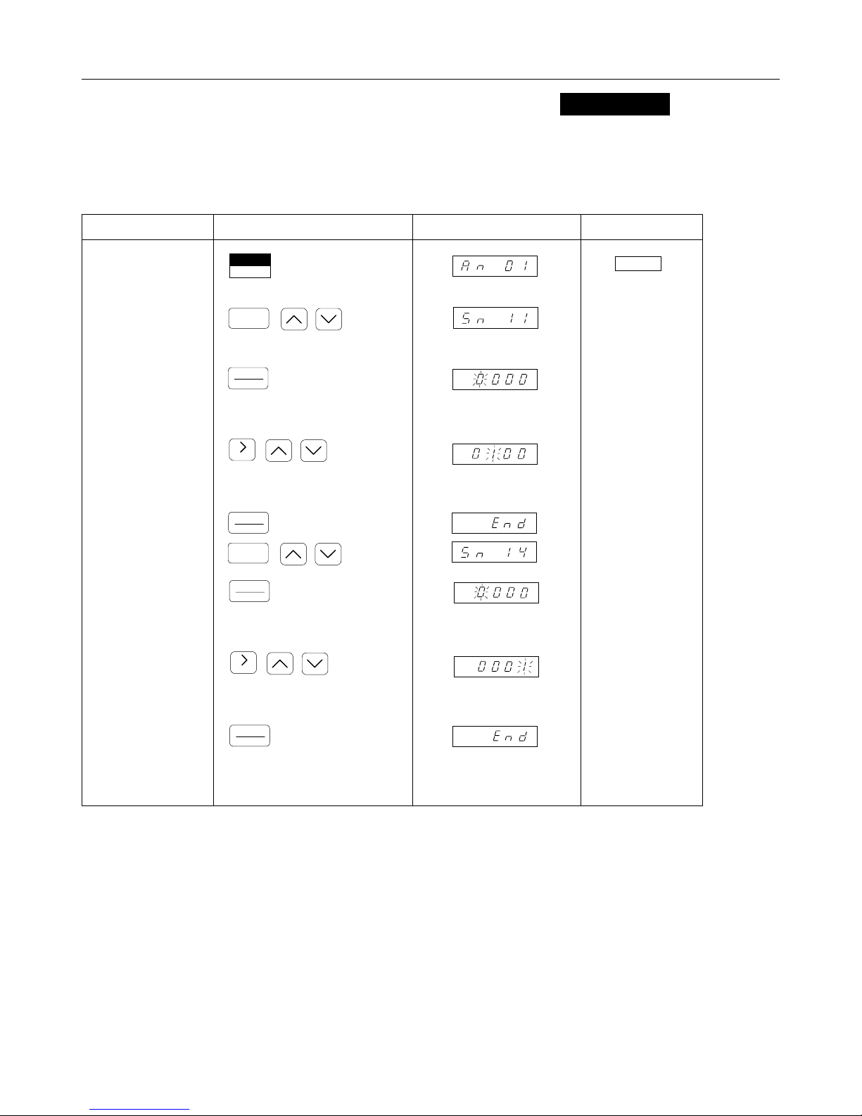
6.4 PROTECTIVE CHARACTERISTICS SELECTION
Sn-10 to -14
Protective characteristics can be selected by Sn-10, Sn-11, Sn-12 and Sn-14.
(Example) Operation is continued after recovery from momentary power loss and the electronic thermal
protection is turned OFF.
Description Keypad Operation Digital Operator Display Remarks
• Select PRGM mode.
• Select Sn-11.
• Constant set value is
displayed.
• Set or change
constant.
• Constant value is
written in.
• Constant set value is
displayed.
• Set or change
constant.
• Constant value is
written in.
DRIVE
PRGM
DSPL
DATA
ENTER
RESET
DATA
ENTER
DSPL
DATA
ENTER
RESET
DATA
ENTER
-
-
-
LED DRIVE OFF
Refer to pages 29
and 30.
Displayed for 0.5
second. Confirm the
display for each
constant.
Displayed for 0.5
second. Confirm the
display for each
constant.
28
─ ─
Page 29
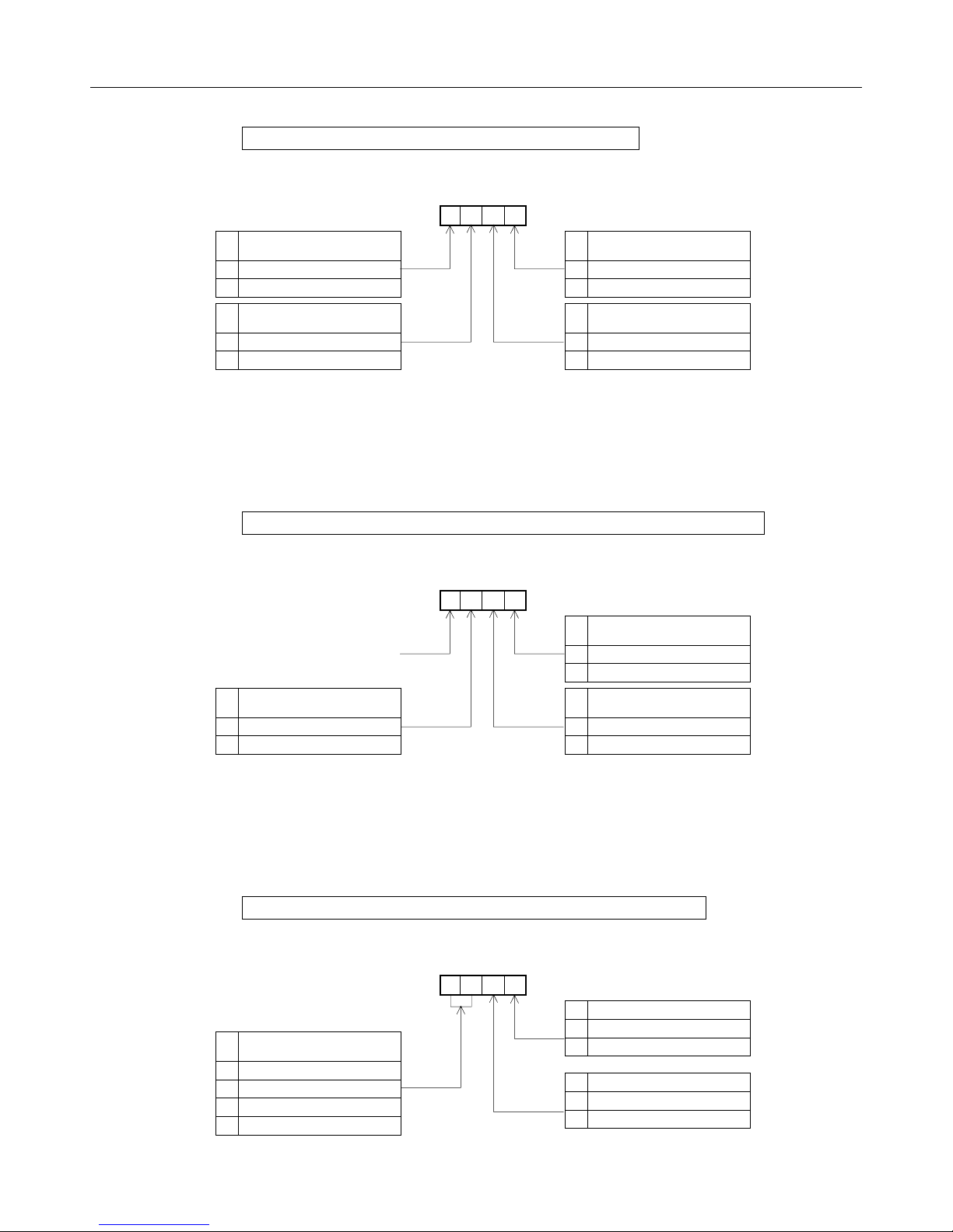
* Protective characteristics
Sn-10 Protective characteristic 1 (stall prevention)
Decel time during stall
prevention
0 bn-02
1 bn-04
Stall prevention during
running
0 Effective
1 Ineffective
4 3 2 1
DIGIT
0 Effective
1 Ineffective
0 Effective
1 Ineffective
Stall prevention during
acceleration
Stall prevention during
deceleration
Sn-11 Protective characteristic 2 (Momentary power loss ride-thru)
4 3 2 1
Operation at momentary
power loss
0 Operation to stop
1 Operation to continue
Not used
DIGIT
0 Ineffective
1 Effective
0 Open
1 Close
Protection for internal braking
resistor
Fault contact during auto
rest/restart operation
Sn-12 Protective characteristic 3 (External fault terminal 3)
4 3 2 1
Processing at external fault
detection
00 Ramp to stop by bn-02
01 Coast to stop
10 Ramp to stop by bn-04
11 Operation to continue
DIGIT
External fault
0 NO contact input
1 NC contact input
External fault
0 Always detected
1 Detected during running
29
─ ─
Page 30
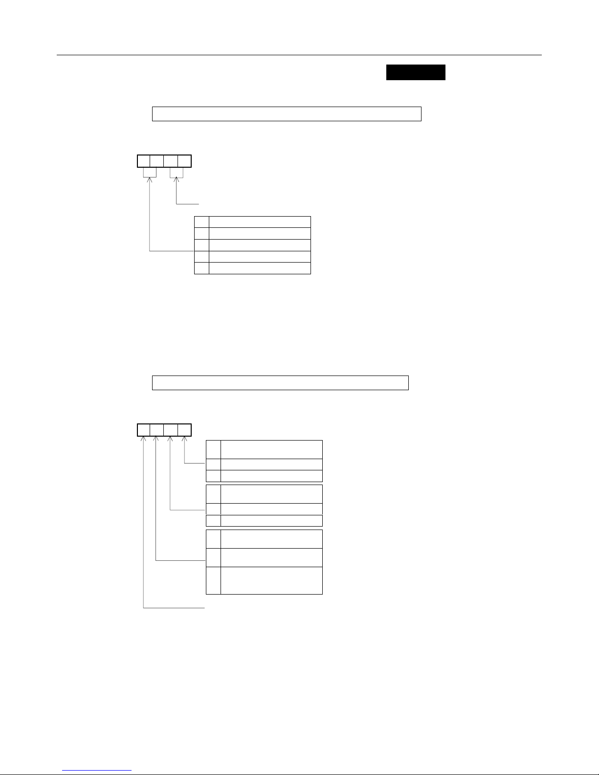
6.4 PROTECTIVE CHARACTERISTICS SELECTION
Sn-13 Protective characteristic 4 (Fan fault protection)
4 3 2 1
DIGIT
Not used
Process at fan fault detection
00 Ramp to stop by bn-02
01 Coast to stop
10 Ramp to stop by bn-04
11 Operation to continue
Sn-10 to -14
(Cont’d)
Sn-14 Protective characteristic 5 (Motor protection)
4 3 2 1
DIGIT
Electronic thermal motor
protection
0 Effective
1 Ineffective
Electronic thermal
characteristics
0 For standard motor
1 For constant torque motor
Electronic thermal time
constant
For standard motor and
0
constant torque motor
For motor other than listed in
1
0 above.
(Short time rating)
Not used
30
─ ─
Page 31

6.5 MULTI-FUNCTION INPUT SELECTION
Sn-04, Sn-15 to -19, bn-09
Response to constant input is selected by the setting of Sn-15 to -19.
(Example 1) 2-step speed operation by analog reference. (Set Sn-04 to 0000)
Keypad Operation Digital Operator Display
DSPL
DATA
ENTER
-
Constant Setting
Set
Terminal Sn-
5 15 3 3
6 16 4 4
7 17 6 6 Jog frequency *
Va l ue
Factory
Setting
Name
Multi-step speed
reference 1
Multi-step speed
reference 2
8 18 8 8
16 19 0 0 Auxiliary frequency
External baseblock
command
* If jog frequency reference and multi-step speed reference
(1, 2) are turned ON simultaneously, jog frequency reference has priority.
MASTER
SPEED
OUTPUT
FREQUENC
AUXILIARY
TIME
MULTI-STEP SPEED
MULTI-STEP SPEED
REFERENCE
TERMINA
FWD RUN
COMMAND
REFERENCE
○
○
○
○
1
5
6
7
OPEN
OPEN
JOG FREQUENCY
CLOSE
CLOS
OPEN
OPEN
OPEN
31
─ ─
Page 32

6.5 MULTI-FUNCTION INPUT SELECTION
MCCB
R
S
T
FWD RUN/STOP
MULTI-STEP
SPEED
REFERENCE 1
MASTER SPEED/
AUXILIARY
CHANGE
2kΩ
MASTER SPEED
FREQUENCY
REFERENCE
0 to 10V
4 to 20mA
AUXILIARY
FREQUENCY
SETTING
0V
2kΩ
P
P
P
Sn-04, Sn-15 to -19, bn-09
GA7200
L1(R)
L2(S)
L3(T)
1
2
3
4
5
6
7
8
11
SEQUENCE COMMON
12
SHIELDED CONNECTION
SPEED SETTING
POWER SUPPLY
15
+15V 20mA
MASTER SPEED
13
REFERENCE
0 to 10V (20kΩ)
14
MASTER SPEED
REFERENCE
16
4 to 20mA (250Ω)
17
AUXILIARY
FREQUENCY
REFERENCE
0V
0 to 10V (20kΩ)
T1(U)
T2(V)
T3(W)
(E)
(Cont’d)
MOTOR
IM
32
─ ─
Page 33

(Example 2) 5-step speed operation + energy-saving operation
(terminal 8)
Keypad Operation Digital Operator Display Remarks
Only check set
value
DSPL
DATA
ENTER
RESET
DATA
ENTER
DSPL
DATA
ENTER
-
-
Displayed for 0.5
second. Confirm the
display for each
constant.
The following shows a sequence to perform 5-step speed operation.
Constant Setting
Set
Terminal Sn-
5 1 3 3
6 16 4 4
Va l ue
Factory
Setting
Name
Multi-step speed
reference 1 *
Multi-step speed
reference 2 É
7 17 6 6 Jog frequency Û
8 18 63 8
* For combination of multi-step speed operations, refer to pages 85 and 86.
ÉFor frequency reference, set in the form of An- .
Û
Jog reference has priority over multi-step speed reference (1,2) when they are
turned ON simultaneously.
Energy-saving
operation
33
─ ─
Page 34

6.5 MULTI-FUNCTION INPUT SELECTION
Sn-04, Sn-15 to -19, bn-09
(Cont’d)
MASTER
SPEED
FREQUENCY
REF.*
(An-01)
AUX.
FREQUENCY
REF.É
(An-02)
FREQUENCY
REF. 3
(An-03)
FREQUENCY
REF. 4
(An-04)
JOG FREQUENCY
(An-09)
TERMINA
0
t
FWD RUN
MULTI-STEP
MULTI-STEP
(MASTER/AUX
JOG FREQUENCY
ENERGY SAVING
OUTPUT
In this area, V/f setting (Cn-02 to -08)
is reduced to the bn-09 setting (%)
* When Sn-04 is set to × × × 1, that value will be the internal set value (An-01).
É When Sn-19 is set with any value other than 00, An-02 will be effective. When multi-function
analog reference input is not used, set 0F as the set value.
34
─ ─
Page 35

(Example 3) 9-step speed operation
Keypad Operation Digital Operator Display Remarks
DSPL
DATA
ENTER
RESET
DATA
ENTER
DSPL
DATA
ENTER
RESET
DATA
ENTER
Constant Setting
Set
Terminal Sn-
5 15 3 3
6 16 4 4
Va l ue
Factory
Setting
Multi-step speed
reference 1 *
Multi-step speed
reference 2 É
-
-
Name
Displayed for 0.5
second. Confirm the
display for each
constant.
Displayed for 0.5
second. Confirm the
display for each
constant.
7 17 6 6
8 18 63 8 Jog frequency Û
Multi-step speed
reference 3
* For combination of multi-step speed operations, refer to pages 85 and 86.
ÉFor frequency reference, set in the form of An- .
Û
Jog reference has priority over multi-step speed reference (1 to 3)
when they are turned ON simultaneously.
35
─ ─
Page 36

6.5 MULTI-FUNCTION INPUT SELECTION
Sn-04, Sn-15 to -19, bn-09
(Cont’d)
MASTER
SPEED
FREQUENCY
REF.*
AUX.
FREQUENCY
REF.É
(An-02)
(An-01)
FREQUENCY
REF. 3
(An-03)
FREQUENCY
REF. 4
FREQUENCY
REF. 5
(An-04)
FREQUENCY
REF. 6
(An-05)
FREQUENCY
REF. 7
(An-07)
(An-06)
FREQUENCY
REF. 8
(An-08)
JOG
FREQUENCY
(An-09)
FWD RUN COMMAND ○
MULTI-STEP
SPEED REFERENCE 1 ○
MULTI-STEP
SPEED REFERENCE 2 ○
MULTI-STEP
SPEED REFERENCE 3 ○
JOG FREQUENCY ○
TERMINAL
5
6
7
8
CLOSED
1
CLOSED
OPEN
CLOSED
OPEN
CLOSED
OPEN
CLOSED
OPEN
OPEN
* When Sn-04 is set to × × × 1, that value will be the internal set value (An-01).
É When Sn-19 is set with any value other than 00, An-02 will be effective. When multi-function
analog reference input is not used, set 0F as the set value.
36
─ ─
Page 37

6.6 CONTACT OUTPUT SELECTION
Contact output function can be selected by the setting of Sn-20.
(Example) Overtorque signal is read out from contact output.
Applicable inverter: 230V, 10HP (rated current 32A)
Applicable motor : 10HP (7.5kW), 4P (motor rated current 26.8A) (TECO
MOTOR)
Overtorque detection level is equivalent to motor rated torque. Set a mode in
which overtorque signal is output only when overtorque is detected during
constant speed running. Inverter rated current is regarded as 100% value.
OUTPUT
CURREN
OVERTORQU
E
DETECTION
Cn-26
OVERTORQU
E
Sn-20
Cn-27
t
CLOSED
37
─ ─
Page 38

6.6 CONTACT OUTPUT SELECTION
Keypad Operation Digital Operator Display Remarks
DSPL
DATA
ENTER
RESET
DATA
ENTER
DSPL
DATA
ENTER
RESET
DATA
ENTER
DSPL
DATA
ENTER
RESET
DATA
ENTER
DSPL
DATA
ENTER
Sn-20
(Cont’d)
-
-
-
-
Displayed for 0.5
second. Confirm the
display for each
constant.
A8.26
A32
=84%
Displayed for 0.5
second. Confirm the
display for each
constant.
%100X
Application Example
As with an extruder, a cutter, or other machines, when a load is
applied beyond a given set value, the machines (particularly cutting
tools) should be protected
.
38
─ ─
Page 39

6.7 FREQUENCY REFERENCE CHANGE
Any output frequency value for frequency set value (0 to 10V or 4 to 20mA) can
be set.
(Example)
Adjust to 10% speed (6Hz) at frequency reference input 4mA and 100% speed at
16.8mA (Set bn-05 = 0122.5 and bn-06 = +010).
Keypad Operation Digital Operator Display Remarks
DSPL
DATA
ENTER
RESET
DATA
ENTER
DSPL
DATA
ENTER
RESET
DATA
ENTER
bn-05, -06
-
-
*1
*2
Displayed for 0.5
second. Confirm the
display for each
constant.
Displayed for 0.5
second. Confirm the
display for each
constant.
39
─ ─
Page 40

(
(
6.7 FREQUENCY REFERENCE CHANGE
122.5
bn-05)
REFERENCE
100
GAI
BIAS
bn-06)
10
4mA
Note: Frequency reference gain (bn-05) and frequency reference bias (bn-06)
can be changed while running in DRIVE mode.
*1 How to calculate gain
X =
b100−
… (1) G = X+b … (2)
a
X is obtained from equation (1)
X =
10100−
= 112.5
8.0
G is obtained by substituting X
obtained in equation (1) to equation
(2).
G = 112.5 + 10 = 122.5
*2 in the uppermost digit indicates “+ (plus).”
-is displayed when it is “(-minus).”
GAI
16.8mA
FREQUENCY REFERENCE INPUT
Application Example
bn-05, -06
(Cont’d)
20mA
a: Reference input ratio at 100%
frequency. Since it is 100%
speed (60 Hz) at 16.8mA in this
example, the following equation
is established.
mA4mA8.16
−
=0.8a =0.8
mA4mA20
−
b: Bias level (%)
Since it is 10% (6Hz) at
frequency requence input 4mA
in this example, the following
equation is established.
b = 10
G: Gain set value
122.5 in this example
For instrumentation input of 4 to 20mA , the amount should be
adjusted at startup. Maximum frequency should be adjusted.
─
40
─
Page 41

6.8 DC INJECTION BRAKING (DC)
DC injection braking at starting or stopping function is selected by the setting of
Cn-10 to -13.
MINIMUM
OUTPUT
FREQUEN
DC INJECTION
(Example) Set 3 seconds to DC injection braking time at starting.
Cn-1
Time Chart of DC injection braking time at starting.
Cn-10 to -13
DC INJECTION
BRAKING
START
Cn-1
Cn-1
DC INJECTION
Keypad Operation Digital Operator Display Remarks
DSPL
DATA
ENTER
RESET
DATA
ENTER
-
Displayed for 0.5
second. Confirm the
display for each
constant.
Application Example
When an idle fan slips and the direction of rotation is indefinite, “OC”
and “OV” trip should be avoided.
41
─ ─
Page 42

6.9 FULL-RANGE DC INJECTION BRAKING STOP (DCB STOP)
Sn-04 = 10XX, Cn-12
When the full-range DC injection braking stop function is used, the inverter can be stopped without a braking
resistor. When stop command is input, DC injection braking stop is executed. DC injection braking time while
stopping is set by Cn-12 at 10% speed and varies according to output frequency at stop command input as
shown below.
RUN
OUTPUT
<Time Chart>
STOP
DC
INJECTIO
N
0.5sec. DC INJECTION
OUTPUT FREQUENCY
(Example)
Full-range DC injection braking stop is selected to set DC injection braking time
to 1 second.
Keypad Operation Digital Operator Display Remarks
Cn-12 X
Cn-12
DC injection brake should be applied sparingly without a braking
resistor. (Within 3 - 5% duty cycle).
DSPL
DATA
ENTER
DATA
ENTER
DSPL
DATA
ENTER
RESET
DATA
ENTER
-
-
Application Example
Displayed for 0.5
second. Confirm the
display for each
constant.
Displayed for 0.5
second. Confirm the
display for each
constant.
42
─ ─
Page 43

6.10 UPPER/LOWER LIMT OF FREQUENCY REFERENCE
Cn-14 , -15
Output frequency upper/lower limit value can be set.
When the lower limit value is less than minimum output frequency, rotation continues at the lower limit value
until frequency reference reaches the value, by inputting the run command.
(Example)
Set upper, lower limit of frequency reference.
Upper limit: 80% of set frequency
Lower limit: 10% of set frequency
Keypad Operation Digital Operator Display Remarks
DSPL
DATA
ENTER
RESET
DATA
ENTER
DSPL
DATA
ENTER
RESET
DATA
ENTER
-
-
Displayed for 0.5
second. Confirm the
display for each
constant.
Displayed for 0.5
second. Confirm the
display for each
constant.
Note: Setting Cn-14 to
109% enables
frequency up to Cn-02
× 1.09 to be output.
Example: Assuming
Cn-02 = 60Hz, Cn-14
FREQUENCY
REF. UPPER
LIMIT
Cn-14
Fref.
60
48
6
= 109Hz, up to 65.4Hz
0
SET FREQUENCY
100
can be output.
However, when
400Hz is exceeded,
the value is clamped
to 400Hz.
Application Example
The maximum air quantity (upper limit) allowed and the
minimum air quantity (lower limit) required should be
maintained for a fan or a blower.
43
─ ─
Page 44

6.11 PROHIBITED (SKIP) FREQUENCY
Cn-16 to -19
When an operation is required to avoid mechanical resonance frequency, the setting prohibited frequency
function is effective.
Setting prohibited frequency is set in Cn-16 to -18 in units of 0.1Hz.
Setting prohibited frequency width is set to Cn-19 in units of 0.1Hz.
INTERNAL
FREQUENCY
Cn-17
Cn-18
Cn-16
Cn-19
Note: Ineffective when
set value is 0.0Hz.
Cn-19
0
SET FREQUENCY
(Example) 30Hz ± 0.5Hz setting is prohibited.
Keypad Operation Digital Operator Display Remarks
DSPL
ENTER
RESET
ENTER
DSPL
ENTER
RESET
ENTER
Operation avoiding mechanical resonance points in HVAC systems
are required.
DATA
DATA
DATA
DATA
-
-
Application Example
44
─ ─
Displayed for 0.5
second. Confirm the
display for each
constant.
Initial value 1.0Hz
Displayed for 0.5
second. Confirm the
display for each
constant.
Page 45

6.12 DISPLAY MODE CHANGE
(Example)
Frequency reference An- is set or read in the units of 0.01%.
Keypad Operation Digital Operator Display Remarks
DSPL
DATA
ENTER
RESET
DATA
ENTER
Operator Display Mode
Cn-20 Unit of Setting / Reading
Cn-20
-
Displayed for 0.5
second. Confirm the
display for each
constant.
0 Units of 0.01Hz
1 Units of 0.01%
Unit of r/min (0 to 39999)
2 to 39
40
to
39999
r/min = 120 × frequency reference (Hz) / Cn-20
(Cn-20 is the number of motor poles)
The position of decimal point is set by the value of the 5th digit of Cn-20.
Value of 5th digit = 0 : Displayed as xxxx
Value of 5th digit = 1 : Displayed as xxx.x
Value of 5th digit = 2 : Displayed as xx.xx
Value of 5th digit = 3 : Displayed as x.xxx
A set value of 100% frequency is determined by the 1st digit to 4th digit of Cn-20.
Example 1 : when the set value of 100% speed is 200.0.
Example 2 : when the set value of 100% speed is 65.00.
Cn-20 = 12000 is entered
Cn-20 = 26500 is entered
45
─ ─
Page 46

6.13 STALL PREVENTION LEVEL WHILE RUNNING Cn-30 (Sn-10)
If the inverter output current exceeds Cn-30 stall prevention level for more than 100ms, the output
frequency will decrease until output current is below value in Cn-30. Once current has dropped below
set value in Cn-30, the inverter rated current will increase back to set value operation. Inverter rated
current is regarded as 100%.
OUTPUT
CURRENT
OUTPUT
FREQUENCY
(Example) Stall prevention level while ring running 120%.
Decel time bn-04 set value.
Keypad Operation Digital Operator Display Remarks
Cn-30
100 ms
t
t
Sn-10 = 00 XX : DECEL TIME bn-02 SET
VALUE
DSPL
DATA
ENTER
RESET
DATA
ENTER
DSPL
DATA
ENTER
RESET
DATA
ENTER
-
-
Displayed for 0.5
second. Confirm the
display for each
constant.
Displayed for 0.5
second. Confirm the
display for each
constant.
Rotation speed should be automatically reduced for rated
operation regardless of possible overload, and on return to normal
load, the previous rotation speed should be maintained.
Application Example
46
─ ─
Page 47

d
6.14 AUTO RESET/RESTART OPERATION AT FAULT (FAULT RETRY)
If a protective function (OC, OV, OL1, OL2, OL3, OH, UV1) operates while running,
auto reset/restart function can be selected. Reset/restart operation can be performed up to 10 times.
By setting Cn-36 to 0, reset/restart operation at fault will not performed.
< Time Chart >
FAULT
DETECTION
OUTPUT
FREQUENCY
FAULT
CONTACT
MOTOR r/min
Sn-11 2
Fault contact output.
n
digit = 1:
Keypad Operation Digital Operator Display Remarks
Cn-36
DSPL
DATA
ENTER
RESET
DATA
ENTER
DSPL
DATA
ENTER
RESET
DATA
ENTER
-
-
Displayed for 0.5
second. Confirm the
display for each
constant.
Displayed for 0.5
second. Confirm the
display for each
constant.
Application Example
If the inverter protection function operates due to lightning surge,
automatic reset will be attempted about four or five times to continue
operation without stopping the motor.
47
─ ─
Page 48

p
Cont
6.15 INITIALIZING CONSTANTS
Sn-03
(Example) Replacing control board.
Select inverter capacity and set V/f pattern and initialize constants.
All constants except Sn-01 (inverter capacity) and Sn-02 (V/f pattern) are initialized to the data at the factory
prior to shipment.
Description Keypad Operation Digital Operator Display Remarks
Power ON
Set inverter
acity
ca
Selec
t
Set V/f pattern
Select
60HZ
stand.
patter
• Frequency reference value
is displayed.
• Select PRGM mode.
• Select inverter capacity
constant (Sn-01).
• Sn-01 data is displayed.
• Change set value.
• Set value is written in.
• Select V/f pattern constant
(Sn- ).
• Select Sn-02.
• Sn-02 data is displayed.
PRGM
DRIVE
DSPL
DATA
ENTER
RESET
DATA
ENTER
DSPL
DATA
ENTER
Depress
twice
-
-
-
-
LED DRIVE OFF.
Displayed for 0.5
second. Confirm the
display for each
constant.
• Change set value.
• Set value is written in.
’
RESET
DATA
ENTER
48
─ ─
Displayed for 0.5
second. Confirm the
display for each
constant.
Page 49

Co
6.15 INITIALIZING CONSTANTS
Description Keypad Operation Digital Operator Display Remarks
Constant is
initialized
End
nt’
• Select initialization
constant.
• Select Sn-03.
• Data is displayed.
• Set to " 1110".
• Set value is written in.
When key is depressed, all constants except Sn-01 and Sn-02 are changed to
DATA
ENTER
the value set priot to shipping.
• Switch to DRIVE mode.
DSPL
ENTER
RESET
ENTER
PRGM
DRIVE
DATA
DATA
Sn-03
-
-
.
Displayed for 0.5
second. Confirm the
display for each
constant.
LED DRIVE
lights.
49
─ ─
Page 50

7. CONSTANTS/FUNCTION LIST
7.1 FREQUENCY REFERENCE
An- .
These references are used during multi-speed operation. Set values of An- can be changed or
read during running in DRIVE mode.
List of An- constants
An-
01 Frequency reference 1 0.01Hz 0.00Hz to 400.00Hz 0.00Hz
02* Frequency reference 2 0.01Hz 0.00Hz to 400.00Hz 0.00Hz
03 Frequency reference 3 0.01Hz 0.00Hz to 400.00Hz 0.00Hz
04 Frequency reference 4 0.01Hz 0.00Hz to 400.00Hz 0.00Hz
05 Frequency reference 5 0.01Hz 0.00Hz to 400.00Hz 0.00Hz
06 Frequency reference 6 0.01Hz 0.00Hz to 400.00Hz 0.00Hz
07 Frequency reference 7 0.01Hz 0.00Hz to 400.00Hz 0.00Hz
08 Frequency reference 8 0.01Hz 0.00Hz to 400.00Hz 0.00Hz
Data Name Unit Setting - Range
Factory
Setting
09 Jog frequency reference 9 0.01Hz 0.00Hz to 400.00Hz 6.00Hz
*Sn-19 must be set to 1.
Note: An- setting/reading units differ according to operator display mode (Cn-20) set values.
The factory setting is 0.01Hz.
--50--
Page 51

7.2 CONSTANTS CHANGE WHILE RUNNING
bn- .
Set values of bn- can be changed or read while running in DRIVE mode.
List of bn- constants
bn-
01 Acceleration time 1 0.1s 0.0 to 6000.0s 10.0s
02* Deceleration time 1 0.1s 0.0 to 6000.0s 10.0s
03 Acceleration time 2 0.1s 0.0 to 6000.0s 10.0s
04 Deceleration time 2 0.1s 0.0 to 6000.0s 10.0s
05 Frequency reference gain 0.1% 0 to 1000.0% I00%
06 Frequency reference bias 1% -100 to 100% 0%
07 Torque compensation gain 0.1 0.0 to 9.9 1.0
08 Motor rated slip 0.1% 0.0 to 9.9% 0.0%
Data Name Unit Setting - Range
Factory
Setting
09 Energy-saving level gain 1% 0 to 200% 80%
10
12 Not used
Monitor no. after turning
ON power supply
11 Analog monitor gain 0.01 0.01 to 2.55 1.00
-
-
1 to 3 1
-
-
--51--
Page 52

7.2 CONSTANT CHANGE WHILE RUNNING
(1) Acceleration Time 1 (bn-01)
Acceleration time 1 is enabled when the accel/decel time change command
of multi-function terminals is “open”, or the accel/decel time change function
is not provided for the multifunction terminals. The acceleration time, in which
frequency reference goes from 0% to 100%, is set in units of 0.1 second.
(2) Deceleration Time 1 (bn-02)
Deceleration time 1 is enabled when the accel/decel time change command
of multi-function terminals is “open”, or the accel/decel time change function
is not provided for the multifunction terminals. The deceleration time, in
which frequency reference goes from 100% to 0%, is set in units of 0.1
second.
(3) Acceleration Time 2 (bn-03)
Acceleration time 2 is enabled when the accel/decel time change command
of multi-function terminals is “closed”. The acceleration time, in which
frequency reference goes from 0% to 100%, is set in units of 0.1 second.
bn-
(Cont'd)
(4) Deceleration Time 2 (bn-04)
Deceleration time 2 is enabled when the accel/decel time change command
of multi-function terminals is “closed”. The deceleration time, in which
frequency reference goes from 100% to 0%, is set in units of 0.1 second.
(5) Frequency Reference Gain (bn-05)
The input level when frequency reference voltage is 10V is set in units of 1%.
Examples are shown below.
(6) Frequency Reference Bias (bn-06)
The input level when frequency reference voltage is 0V is set in units of 1%.
< Example >
bn-05 = 50
1
○
a: bn-06 = 10
2
○
b: bn-06 = -10
INPUT LEVEL
%
bn-05
10
bn-06
(a)
bn-06
(b) -10
bn-06 is positive value
0
0V
bn-06 is
negative value
10V
FREQUENCY
REFERENCE
--52--
Page 53

(7) Torque Compensation Gain (bn-07)
Torque compensation gain is set in units of 0.1.
(8) Motor Rated Slip (bn-08)
Motor Rated slip is set in units of 0.1%
TORQUE
Simplified speed control is performed
without encoder (PG or TG).
f1
SMALL LOAD
f2
LARGE LOAD
With frequency offset f
fluctuation due to load is reduced.
to f2, speed
1
When the output current of the inverter is larger than motor no-load current
(Cn-34), the output frequency of the inverter is compensated.
The amount of frequency compensation is determined by the formula below.
The maximum voltage frequency (Cn-04) is 100%.
LOAD TORQUE
SPEED
If the output current is equal to the motor rated current (Cn-09), the output
frequency is compensated for by the motor rated slip (bn-08).
If frequency reference is equal to or smaller than minimum output frequency
(Cn-07) or motor is in a regeneration mode, slip compensation is not performed.
The amount of output frequency compensation in a constant torque area and
a constant output area is shown in the figure below.
Amount of output frequency compensation =
motor rated slip
motor rated
current
motor no-load
-
current
output
-
×
current
motor no-load
current
Cn-04xbn-08
bn-08
Cn-04
Cn-02
Motor rated current: Cn-09
Motor no-load current: Cn-34
Motor rated slip: bn-08
When 0.0 is set in bn-08, output frequency compensation is not performed.
--53--
Page 54

7.2 CONSTANT CHANGE WHILE RUNNING
(9) Energy-saving Level Gain (bn-09)
Energy-saving level gain is set in units of 1%.
(10) Monitor No. after Turning ON Power Supply (bn-10)
Data to be monitored after turning ON power supply is selected with constant
No. in the form of Un- .
1
○
Frequency reference
2
○
Output frequency
3
○
Output current
(11) Multi-function Analog Output (bn-11)
The multi-function analog output is set in the form of 10V × XX.
<Example> When 5V is set as the 100% level, specify bn-11=0.5.
(12) Calibrating Meter
Multi-function analog output.
bn-
(Cont'd)
When bn-11 is displayed in PRGM mode, a 100%-Ievel voltage is output by
the set value of bn-11.
Multi-function
Analog Output
The item to be monitored is
selected by 4th digit of
Sn-05 or 2nd digit of Sn-09.
10.0V × bn-11
Diagram of Multi-function Analog Output
Terminal 21
--54--
Page 55

7.3 SYSTEM CONSTANTS
Sn-
Sn-
System Constants List (1/5)
Factory
Setting
Function
Setting
Constant
Operator
Status
Operation
Mode
Selection 1
Data Name Description
4th Digit
3rd Digit
01 Inverter Capacity Inverter capacity selection ——*1 Basic
02 V/f V/f pattern selection 01
Display of
Operator
03
Constants
Initialization
Operation
Method Selection
04
0000
0101
1110
1111
Master frequency reference by analog input
of control circuit terminals 13, 14
Master frequency reference from keypad
Control circuit terminal operation effective
Keypad operation reference effective
RAMP stop 0 0
Setting and reading of An- , bn- , Sn- ,
Cn- enabled
Setting and reading of An- : reading of bn- ,
Sn- , Cn- enabled
Constants initialization (Multi-function terminals are preset
prior to shipping) *2
Constants initialization (For multi-function terminals, refer to
Table of *2)
4th
3rd
Digit
Digit
- - -
- - -
- -
- -
2nd
Digit
0
1
- -
1st
Digit
0
1
-
-
0000
0011
1st Digit
2nd Digit
Operation
Mode
Selection 2
Stopping Method
Selection
Priority of
Stopping
REV RUN
Prohibit
05
Control Input
Scan
Analog Monitor
Output
Coast to stop 0 1
Full-range DC injection braking stop 1 0
Coast to stop (timer function provided) 1 1
STOP key effective during operation from
control terminal.
STOP key ineffective during operation from
control terminal.
REV RUN enabled
REV RUN disabled
Control inputs are scanned twice before
being accepted by MPU.
Control inputs are scanned once before
being accepted by MPU.
Selection of item to be analog output
(terminals 21,22) *3
Selection of item to be analog output
(terminals 21,22) *3
- - -
- - -
- -
- -
-
-
- - -
0
- - -
1
--55--
0
1
- -
- -
- -
0
1
- -
- -
0
1
-
-
0000
Page 56

Function
Sn-
System Constants List (2/5)
Data Name Description
Factory
Setting
4th Digit
3rd Digit
2nd Digit
1st Digit
4th
Digit
3rd
Digit
2nd
Digit
1st
Digit
Operation
Mode
Selection 3
Operation
Mode
Selection 4
(Overtorque
Detection)
S-curve at Accel /
Decel Time
06
Input Reference
Processing
When Frequency
Reference is
Missing
Overtorque
07
Detection
0.2 second S-curve
No S-curve
S-curve 0.5 second
S-curve 1.0 second
Response to master frequency reference:
0 to 100% at 0 to 10V (4 to 20mA)
Response to master frequency reference:
0 to 100% at 10 to 0V (20 to 4mA)
Stop by reference input 0
Operation to continue with 80% of frequency
reference
Overtorque detection disabled
Overtorque detection enabled
Enabled only if at agreed frequency
Enabled during operation (except during DC
injection)
Operation continued after overtorque is
detected
Coasts to stop if overtorque is detected
- -
- -
- -
- -
-
-
- - -
- - -
- -
- -
-
-
0
1
- - -
- - -
1
0
1
0 0
0 1
1 0
1 1
- -
- -
0
1
- -
- -
0000
0
1
-
-
0000
Operation
Mode
Selection 5
Priority of
Frequency
Reference
(When input
option card is
used)
Priority of Run
Command
(When input
08
option card is
used)
Stopping Method
Selection at
Communication
Interface Card
(SC-C)
Communication
Error
Not used 0
Frequency reference is from option card
(if installed)
Frequency reference is from inverter
Run command is from option card
(if installed)
Run command is from inverter
Ramp stop (decel time: bn-02) 0 0
Coast to stop 0 1
Ramp stop (decel time: bn-04) 1 0
Operation to continue 1 1
- - -
- - -
- -
- -
--56--
- - -
0
1
- -
- -
- -
- -
0
1
-
-
0100
Page 57

7.3 SYSTEM CONSTANTS
Sn-
Function
Data Name Description
Sn-
(Cont’d)
System Constants List (3/5)
4th
Digit
3rd
Digit
2nd
Digit
1st
Digit
Factory
Setting
4th Digit
3rd Digit
2nd Digit
1st Digit
Operation
Mode
Selection 6
Protective
Characteristic
Selection 1
(Stall
Prevention)
Protective
Characteristic
Selection 2
Analog Output
Selection Method
09
Analog Monitor
Selection
——— ——— 0 0
10 Stall Prevention
DB Resistor
Fault Contact
during Auto
Reset/Restart
11
Operation
Analog output (terminals 21-22) depends on
Sn-05 4th digit and Sn-09 2nd digit
Analog output (terminals 21-22) is set by
communication interface card (SC-C)
Analog output (terminals 21-22) *3
Analog output (terminals 21-22) *3
Stall prevention during acceleration enabled
Stall prevention during acceleration disabled
Stall prevention during deceleration enabled
Stall prevention during deceleration disabled
Stall prevention during running enabled
Stall prevention during running disabled
Decel time during stall prevention: “DECEL
TIME 1” (bn-02 set value)
Decel time during stall prevention: “DECEL
TIME 2” (bn-04 set value)
No. DB protection calculated or provided by
inverter
Protection provided for TECO DB resistor
only, if installed
Fault contact is not energized during auto
reset/restart operation
Fault contact is energized during auto
reset/restart operation
Operation stopped by momentary power loss
detection
Operation continues after momentary power
loss
- - -
- - -
- -
- -
- - -
- - -
- -
- -
-
-
0
1
- - -
- - -
- -
- -
-
-
0
1
- - -
- - -
0
1
0
1
- -
0
1
- -
- -
0
1
- -
- -
0
1
-
-
0
1
-
-
0
1
-
-
0000
0000
0000
——— Not used 0
--57--
- - -
Page 58

7.3 SYSTEM CONSTANTS
Sn-
Function
Data Name Description
Sn-
(Cont’d)
System Constants List (4/5)
4th
Digit
3rd
Digit
2nd
Digit
1st
Digit
Factory
Setting
4th Digit
3rd Digit
2nd Digit
1st Digit
Protective
Characteristic
Selection 3
Protective
Characteristic
Selection 4
Protective
Characteristic
Selection 5
External Fault
Signal Level
Receiving
External Fault
Signal
12
Processing at
External Fault
Detection
13 Not used ——— — — — — ——
Motor Protection
(Electronic
Thermal)
14
Inverter
Protection
(Electronic
Thermal) *4
External fault input: NO-contact input
External fault input: NC-contact input
External fault signal: Always detected
External fault signal:
Detected during running only
Ramp stop (major fault) 0 0
Coast to stop (major fault) 0 1
Ramp stop (major fault):
ramp stop (bn-04 set value)
Operation to continue (minor fault) 1 1
Electronic thermal motor protection effective
Electronic thermal motor protection
ineffective
Electronic thermal characteristics are in
accordance with standard motor
Electronic thermal characteristics are in
accordance with constant torque motor
Electronic thermal time constants are
standard
Electronic thermal time constants are
short-time rated
Inverter Protection OL: 103% continuous,
150% for one minute
Inverter Protection OL: 113% continuous,
123% for one minute
- - -
- - -
- -
- -
1 0
- - -
- - -
- -
- -
-
0
-
1
- - -
0
- - -
1
0
1
- -
- -
- -
- -
0
1
- -
- -
0
1
-
-
0100
0
1
-
-
0000
--58--
Page 59

7.3 SYSTEM CONSTANTS
Sn-
Function
Contact
Input
Multi-function Selection
Signal
Analog
Input
Output
Signal
15
16
17
18
19
20
21
22
25 Not used —— —— ——
26 Not used —— —— ——
Data Name Description
Set Data
Terminal 5
Function
Terminal 6
Function
Terminal 7
Function
Terminal 8
Function
Multi-function
Analog Input
Multi-function
Output 1
Multi-function
Output 2
Multi-function
Output 3
00 - FF
00 - FF
00 - FF
00 - FF
00 - FF Selects multi-function analog input (terminal 16) function 00
00 - FF
00 - FF
00 - FF
Sn-
(Cont’d)
System Constants List (5/5)
Selects terminal 5 function (factory preset for multi-step
speed reference 1)
Selects terminal 6 function (factory preset for multi-step
speed reference 2)
Selects terminal 7 function (factory preset for jog
frequency reference)
Selects terminal 8 function (factory preset for internal
baseblock by NO contact input)
Selects multi-function contact output (terminals 9, 10)
function (factory preset for during running)
Selects multi-function open collector (terminal 25) function
(factory preset for zero speed)
Selects multi-function open collector (terminal 26) function
(factory preset for agreed frequency)
4th
Digit
3rd
Digit
2nd
Digit
1st
Digit
Factory
Setting
4th Digit
3rd Digit
2nd Digit
03
04
06
08
00
01
02
1st Digit
Option Card
Function
Selection
-
Pulse Monitor
Card PM-C
(Number of
Output Pulses)
27
F: Inverter
Output
Frequency
28 Not used —— —— ——
X1 of inverter output frequency (1F) 0 0 0
X6 of inverter output frequency (6F) 0 0 1
X10 of inverter output frequency (10F) 0 1 0
X12 of inverter output frequency (12F) 0 1 1
X36 of inverter output frequency (36F) 1 0 0
-
001-
-
-
-
--59--
Page 60

*1 Differs according to inverter capacity.
*2 Initialization (Sn-03 = 1110, 1111)
After depressing the ENTER key, input the initial value of An- , bn- , Sn- , Cn- , (except Sn-01,Sn-02) into NV-RAM.
When the value is written in without an error, is displayed. When the value is written in with an error, is displayed. The values of
Sn-15 to -18 differ as follows between initializations with Sn-03 = 1110 and with Sn-03 = 1111.
Multi-function
Terminal
Terminal 5 (Sn-15) 3* (Multi-step speed command 1) 0 (FWD/REV run select)
Terminal 6 (Sn-16) 4* (Multi-step speed command 2) 3 (Multi-step speed reference 1)
Terminal 7 (Sn-17) 6* (Jog frequency reference) 4 (Multi-step speed reference 2)
Terminal 8 (Sn-18) 8* (External baseblock command) 6 (Jog frequency reference)
* Values have been factory-set.
*3 Setting of Sn-05 4th digit and Sn-09 2nd digit.
Sn-05
4th Digit
0 0
1 0
0 1
1 1
*4 Effective only for inverter models of capacity 230V 40HP (30kW) or more, 460V 75HP (55kW) or more.
Sn-09
2nd Digit
1110
(2 Wire Sequence)
Output analog signal proportional to inverter output frequency.
(Max. frequency/100%)
Output analog signal proportional to inverter output current.
(Rated current/100%)
Output analog signal proportional to inverter output voltage reference.
(Cn-01/100%)
Output analog signal proportional to inverter output power.
(Max. applicable motor capacity/100%)
1111
(3 Wire Sequence)
Description
--60--
Page 61

▓ Inverter Capacity Selection Sn-01
Inverter capacity has been preset at the factory. However, if a spare control board is used, reset the
inverter capacity referring to the table below. Control constant Cn- factory setting values (initial
values) differ according to Sn-01 setting.
230V Class
Inverter Capacity Selection
Data of Sn-01
Name
Inverter rating HP 0.5 1 2 3 5 7.5 10 15
Inverter rated capacity kVA 1.4 2.1 2.7 4.1 6.9 10.3 13.7 20.6
00 01 02 03 04 05 06 07
Max. applicable motor capacity HP (kW)
Inverter rated current A 3.2 4.8 6.4 9.6 16 24 32 48
Cn-09 Motor rated current A 1.9 3.4 6.1 8.7 13.5 20.1 25.1 36.7
Cn-23
Cn-24
Cn-25
Cn-31
Cn-32
Factory Setting
Cn-33
Cn-37
Carrier frequency upper
limit kHz
Carrier frequency lower
limit kHz
Carrier frequency
proportional gain
Motor phase-to-phase
resistance Ω
Torque compensation iron
loss W
Torque compensation limit
V
Momentary power loss
assurance time s
0.5
(0.4) 1 (0.75) 2 (1.5) 3 (2.2) 5 (3.7)
15.0 15.0 15.0 15.0 15.0 15.0 15.0 15.0
15.0 15.0 15.0 15.0 15.0 15.0 15.0 15.0
0 0 0 0 0 0 0 0
11.760 5.732 2.407 1.583 0.684 0.444 0.288 0.159
48 64 108 142 208 252 285 370
50 50 50 50 50 50 50 50
0.7 1.0 1.0 1.0 2.0 2.0 2.0 2.0
7.5
(5.5)
10
(7.5)
15
(11)
Cn-40 Minimum baseblock time s 0.5 0.5 0.5 0.5 0.5 0.7 0.7 0.7
Cn-41 V/f during speed search % 100 100 100 100 100 100 100 100
--61--
Page 62

7.3 SYSTEM CONSTANTS Sn- (Cont’d)
Inverter Capacity Selection
230V Class
Data of Sn-01
Name
Inverter rating HP 20 25 30 40 50 60 75 100
Inverter rated capacity kVA 27.4 34 41 54 68 78 95 130
Max. applicable motor capacity HP (kW)
Inverter rated current A 64 80 96 130 160 183 224 300
Cn-09 Motor rated current A 50.3 62.9 72.9 96.7 124 143.5 183.5 230
08 09 0A 0B 0C 0D 0E 0F
20
25
30
(15)
(18.5)
(22)
40
(30)
50
(37)
60
(45)
75
(55)
100
(75)
Cn-23
Cn-24
Cn-25
Cn-31
Cn-32
Factory Setting
Cn-33
Cn-37
Cn-40 Minimum baseblock time s 0.7 1.0 1.0 1.0 1.0 1.0 1.0 1.0
Cn-41 V/f during speed search % 100 100 100 80 80 80 80 80
Carrier frequency upper
limit kHz
Carrier frequency lower
limit kHz
Carrier frequency
proportional gain
Motor phase-to-phase
resistance Ω
Torque compensation iron
loss W
Torque compensation limit
V
Momentary power loss
assurance time s
15.0 15.0 15.0 10.0 10.0 10.0 10.0 10.0
15.0 15.0 15.0 10.0 10.0 10.0 10.0 10.0
0 0 0 36 36 36 36 36
0.109 0.077 0.060 0.041 0.033 0.028 0.019 0.007
471 425 582 536 641 737 790 1800
50 50 50 50 50 50 50 50
2.0 2.0 2.0 2.0 2.0 2.0 2.0 2.0
--62--
Page 63

Inverter Capacity Selection
460V Class
Data of Sn-01
Name
Inverter rating HP 0.5 1 2 3 5 7.5 10 15 20 25 30
Inverter rated capacity kVA 1.4 2.1 3.4 4.1 6.9 10.3 13.7 20.6 27.4 34 41
20 21 22 23 24 25 26 27 28 29 2A
Max. applicable motor capacity HP (kW)
Inverter rated current A 1.6 2.6 4.0 4.8 8 12 16 24 32 40 48
Cn-09 Motor rated current A 1.0 1.7 2.9 4.0 6.8 10.0 12.6 18.6 24.8 31.1 36.3
Cn-23
Cn-24
Cn-25
Cn-31
Cn-32
Factory Setting
Cn-33
Cn-37
Carrier frequency upper
limit kHz
Carrier frequency lower
limit kHz
Carrier frequency
proportional gain
Motor phase-to-phase
resistance Ω
Torque compensation iron
loss W
Torque compensation limit
V
Momentary power loss
assurance time s
0.5
(0.4) 1 (0.75) 2 (1.5) 3 (2.2) 5 (3.7)
15.0 15.0 15.0 15.0 15.0 15.0 15.0 15.0 15.0 15.0 15.0
15.0 15.0 15.0 15.0 15.0 15.0 15.0 15.0 15.0 15.0 15.0
0 0 0 0 0 0 0 0 0 0 0
22.929
47.02
48.1 63.9 108 142 208 252 285 370 471 425 582
100 100 100 100 100 100 100 100 100 100 100
1.0 1.0 1.0 1.0 2.0 2.0 2.0 2.0 2.0 2.0 2.0
9.629 6.333 2.735 1.776 1.151 0.634 0.436 0.308 0.239
7.5
(5.5)
10
(7.5)
15
(11)
20
(15)
25
(18.5)
30
(22)
Cn-40 Minimum baseblock time s 0.5 0.5 0.5 0.5 0.5 0.7 0.7 0.7 1.0 1.0 1.0
Cn-41 V/f during speed search % 100 100 100 100 100 100 100 100 100 100 100
--63--
Page 64

7.3 SYSTEM CONSTANTS Sn- (Cont’d)
Inverter Capacity Selection
460V Class
Data of Sn-01
Name
Inverter rating HP 40 50 60 75 100 125 150 175 215 250 350 450
Inverter rated capacity kVA 54 68 82 110 138 180 195 230 260 290 385 514
Max. applicable motor capacity HP (kW)
Inverter rated current A 64 80 96 128 165 192 224 270 300 340 450 600
Cn-09 Motor rated current A 48.7 59.0 70.5 88.0 114 143 175 206 235 290 348 465
2B 2C 2D 2E 2F 30 31 32 33 34 35 36
40
50
60
75
(30)
(37)
(45)
(55)
100
(75)
125
150
(110)
175
215
(160)
250
(185)
350
(264)
(330)
450
Cn-23
Cn-24
Cn-25
Cn-31
Cn-32
Factory Setting
Cn-33
Cn-37
Cn-40 Minimum baseblock time s 1.0 1.0 1.0 1.0 1.0 1.0 2.0 2.0 2.0 2.0 2.0 2.0
Cn-41 V/f during speed search % 100 100 100 80 80 80 80 80 80 80 80 80
Carrier frequency upper
limit kHz
Carrier frequency lower
limit kHz
Carrier frequency
proportional gain
Motor phase-to-phase
resistance Ω
Torque compensation iron
loss W
Torque compensation limit
V
Momentary power loss
assurance time s
15.0 10.0 10.0 10.0 10.0 10.0 10.0 10.0 10.0 2.0 2.0 2.0
15.0 10.0 10.0 10.0 10.0 10.0 10.0 10.0 10.0 1.0 1.0 1.0
0 0 0 0 0 0 0 0 0 0 0 0
0.164 0.133 0.110 0.074 0.027 0.036 0.036 0.020 0.022 0.020 0.022 0.014
536 641 737 790 1800 2900 2900 2600 2500 2600 1850 3600
100 100 100 100 100 100 100 100 100 100 100 100
2.0 2.0 2.0 2.0 2.0 2.0 2.0 2.0 2.0 2.0 2.0 2.0
--64--
Page 65

V/f Pattern Selection Sn-02
V/f pattern is selected by the setting of Sn-02. When V/f pattern is selected, set input voltage of the
inverter in Cn-01.
Data ○0 - ○
E
(of Sn-02): Change disabled
Data ○
(V/f patterns are shown on the following pages).
F
(of Sn-02): Change enabled
--65--
Page 66

7.3 SYSTEM CONSTANTS
Sn-
(Cont’d)
V/f Pattern for 230V Class* 0.5 to 2 HP (0.4 to 1.5kW)
Specifications Sn-02 V/f PatternÉ Specifications Sn-02 V/f PatternÉ
50Hz
(V)
220
0
○
0
○
16 20
11 14
0 1.3 2.5 50
50Hz
(Hz)
Low
Starting
torque
High
Starting
torque
8
○
9
○
(V)
220
31
25
15 20
13 18
0 1.3 2.5 50
9
○
8
○
(H
z)
60Hz
Saturation
60Hz
50Hz
General-purpose
Saturation
72Hz
Variable
torque 1
50Hz
Variable
torque 2
1
○
F
2
○
(V)
220
2
○
16 20
11 14
0 1.5 3 50 60
1
○
F
○
(Hz)
High Starting TorqueÚ
60Hz
Low
Starting
torque
High
Starting
torque
A
B
(V)
220
25 31
25 20
15 22
3 18
0 1.5 3 60
(V)
220
3
○
3
○
16 20
11 14
0 1.5 3 60 72
1.8 3.6
90Hz C
(
Hz)
220
16 20
11 14
(V)
4
○
5
○
(V)
220
55
39
11 13
9 11
0 1.3 25 50
5
○
4
○
(H
z)
120Hz D
220
39 20
20 14
(V)
B
○
A
○
(Hz)
C
○
0 1.5 3 60 90
(Hz)
D
○
0 1.5 3 60 120
3 6
(Hz)
Variable
torque 3
Variable Torque Characteristics
60Hz
Variable
torque 4
6
○
7
○
(V)
220
55
39
11 13
9 11
0 1.5 30 60
* For 460V class, 2 times voltage value shown in table above.
É
Consider the following items as conditions for selecting a V/f pattern.
They must be suitable for:
(1) The voltage and frequency characteristics of the motor.
(2) The maximum rotation speed of the motor.
Ú
Select high starting torque only in the following conditions. Normally, this selection is not required.
(1) The wiring distance is long [492ft (150m) and above].
(2) Voltage drop at startup is large.
(3) AC reactor is inserted in the input or output of the inverter.
(4) A motor smaller than the maximum applicable inverter is used.
Rated Output Operation (Machine tool)
7
○
6
○
(Hz
)
180Hz E
220
33 20
28 14
(V)
E
○
0 1.5 3 60 180
4.5 6
(Hz)
--66--
Page 67

V/f Pattern of 230V Class* 3 to 60 HP (2.2 to 45kW)
Specifications Sn-02 V/f PatternÉ Specifications Sn-02 V/f PatternÉ
50Hz
(V)
220
0
○
0
○
16
11
0 1.3 2.5 50
50Hz
(Hz)
Low
Starting
torque
High
Starting
torque
8
○
9
○
(V)
220
25 28
20 22
15
13
0 1.3 2.5 50
9
○
8
○
(H
z)
60Hz
Saturation
60Hz
50Hz
General-purpose
Saturation
72Hz
Variable
torque 1
50Hz
Variable
torque 2
1
○
F
2
○
(V)
220
2
○
16
11
0 1.5 3 50 60
High Starting TorqueÚ
1
○
F
○
(Hz)
60Hz
Low
Starting
torque
High
Starting
torque
A
B
(V)
220
25 28
20 22
20
14 13
0 1.5 3 60
(V)
220
3
○
3
○
16
11
0 1.5 3 60 72
1.8 3.6
90Hz C
(
Hz)
220
16
11
(V)
4
○
5
○
(V)
220
5
○
55
39
11
9
0 1.3 25 50
120Hz D
4
○
(H
z)
220
38 16
20 11
(V)
B
○
A
○
(Hz)
C
○
0 1.5 3 60 90
2.5 4.5
(Hz)
D
○
0 1.5 3 60 120
3 6
(Hz)
Variable
torque 3
Variable Torque Characteristics
60Hz
Variable
torque 4
6
○
7
○
(V)
220
55
39
11
9
0 1.5 30 60
* For 460V class, 2 times voltage value shown in table above.
É
Consider the following items as conditions for selecting a V/f pattern.
They must be suitable for:
(1) The voltage and frequency characteristics of the motor.
(2) The maximum rotation speed of the motor.
Ú
Select high starting torque only in the following conditions. Normally, this selection is not required.
(1) The wiring distance is long [492ft (150m) and above].
(2) Voltage drop at startup is large.
(3) AC reactor is inserted in the input or output of the inverter.
(4) A motor smaller than the maximum applicable inverter is used.
Rated Output Operation (Machine tool)
7
○
6
○
(Hz
)
180Hz E
220
33 16
28 11
(V)
E
○
0 1.5 3 60 180
4.5 6
(Hz)
--67--
Page 68

7.3 SYSTEM CONSTANTS
Sn-
(Cont’d)
V/f Pattern of 230V Class* 75 and 100HP (55 and 75kW), (75 to 450HP for 460V class)
Specifications Sn-02 V/f PatternÉ Specifications Sn-02 V/f PatternÉ
(V)
9
○
8
○
0 1.3 2.5 50
(H
50Hz
(V)
220
0
0
○
○
14
8
0 1.3 2.5 50
50Hz
(Hz)
Low
Starting
torque
High
Starting
torque
8
○
9
○
220
25
20
13
11
z)
60Hz
Saturation
60Hz
50Hz
General-purpose
Saturation
72Hz
Variable
torque 1
50Hz
Variable
torque 2
1
○
F
2
○
(V)
220
2
○
14
8
0 1.5 3 50 60
High Starting TorqueÚ
1
○
F
○
(Hz)
60Hz
Low
Starting
torque
High
Starting
torque
A
B
(V)
220
25
20
11
0 1.3 3 60
(V)
220
3
3
○
○
14
8
0 1.5 3 60 72
90Hz C
(
Hz)
220
14
8
(V)
4
○
5
○
(V)
220
5
○
55
38
10
8
0 1.3 25 50
120Hz D
4
○
(H
z)
220
14
8
(V)
B
○
A
○
(Hz)
C
○
0 1.5 3 60 90
(Hz)
D
○
0 1.5 3 60 120
(Hz)
Variable
torque 3
Variable Torque Characteristics
60Hz
Variable
torque 4
For 460V class, 2 times voltage value shown in table above.
*
Consider the following items as conditions for selecting a V/f pattern.
É
6
○
7
○
(V)
220
55
38
10
8
0 1.5 30 60
They must be suitable for:
(1) The voltage and frequency characteristics of the motor.
(2) The maximum rotation speed of the motor.
Ú Select high starting torque only in the following conditions. Normally, this selection is not required.
(1) The wiring distance is long [492ft (150m) and above].
(2) Voltage drop at startup is large.
(3) AC reactor is inserted in the input or output of the inverter.
(4) A motor smaller than the maximum applicable inverter is used.
# Up to 100HP (75kW) for 230V class.
Rated Output Operation (Machine tool)
7
○
6
○
(Hz
)
180Hz E
220
(V)
14
8
E
○
0 1.5 3 60 180
(Hz)
--68--
Page 69

Operation Mode Selection 1 Sn-04
(1) 1st digit
1st digit = 0: Reference input from control circuit terminal 13 or 14 is the master speed frequency
reference.
1st digit = 1: Frequency reference 1 (An-01) is the master speed frequency reference.
Note: For combination of multi-step speed operation, refer to pages 36 and 85.
(2) 2nd digit
2nd digit = 0: Run command from control circuit terminal is accepted.
2nd digit = 1: Run command from the digital operator is accepted.
Valid run command and frequency references differ as shown in the table below, depending on the
combination of the 1st and 2nd digits.
CONSTANT
REFERENCE
Control
Terminal
Operator
Valid only when the inverter stops. (FWD run command, REV run command, and DC injection braking command are "open".)
Ä
FWD/REV run command is not accepted.
É
When the STOP key is depressed, processing differs as follows, depending on the setting of the 1st digit of Sn-05.
Ú
1st digit = 0: During running by signals from control circuit terminals, the STOP key from the operator is accepted.
If the STOP key is depressed, the inverter stops according to the setting of 3rd and 4th digits of Sn-04, while the STOP LED indicator blinks.
This stop command is held within the inverter until both the FWD run command and REV run command of control circuit terminals become
"open", or another frequency reference is selected in the multi-step speed command or jog frequency reference section.
1st digit=1: During running by signals from control circuit terminals, the STOP key from the operator is not accepted.
SYSTEM CONSTANTS 4
Master Speed Frequency Reference
FWD Run Command (Terminal 1)
REV Run Command (Terminal 2)
External Fault (Terminal 3)
Fault Reset (Terminal 4)
Command of Terminal 5
Command of Terminal 6
Command of Terminal 7
Command of Terminal 8
Aux. Input
Fault Contact Output
Multi-function Contact Output
Multi-function PHC Output
RUN Key × ×
JOG Key × ×
STOP Key
FWD/REV Key × ×
>/RESET Key
DRIVE/PRGM Key
REF LED Lit OFF Lit OFF
SEQ LED Lit Lit OFF OFF
Monitor display
(frequency reference selection)
(run command selection)
2nd digit 1st digit 2nd digit 1st digit 2nd digit 1st digit 2nd digit 1st digit
0 0 0 1 1 0 1 1
Control circuit
terminal 13, 14
○ ○
○ ○
○ ○ ○ ○
Ä
○ ○
○ ○ ○ ○
○ ○ ○ ○
○ ○ ○ ○
○ ○ ○ ○
○ ○ ○ ○
○ ○ ○ ○
○ ○ ○ ○
Ú
Ä
Valid only when
inverter stopped
○ ○ ○ ○
An-01
Ä
Ú
Ä
Valid only when
inverter stopped
Control circuit
terminal 13, 14
Valid only when
inverter stopped
An-01
× ×
× ×
Ä
É
○ ○
○ ○
○ ○
○ ○
Ä
Ä
É
Ä
Valid only when
inverter stopped
--69--
Page 70

7.3 SYSTEM CONSTANTS
(
(3) 3rd digit, 4th digit
Stop method differs by the setting of 3rd and 4th digits as shown below.
1
Sn-
○
04 = 00 XX RAMP stop
OUTPUT FREQUENCY
RUN COMMAND
2
○
Sn-04 = 01 XX Coast to stop
Sn-
(stop method selection)
DC INJECTION BRAKING
START FREQUENCY
Cn-10)
(Cont’d)
CLOSED
OPEN
DECELERATION TIME
DC INJECTION
DC Injection Braking time
at Stopping (Cn-12)
OUTPUT FREQUENCY
RUN COMMAND
CLOSED
OPEN
WHEN STOP REFERENCE
IS INPUT, INVERTER
OUTPUT IS CUTOFF.
--70--
Page 71

3
(
○
Sn-04 = 10 XX Full-range DC injection braking stop
DC injection braking time differs by the output frequency when stop
command is input as shown below.
RUN COMMAND
OUTPUT FREQUENCY
CLOSED
OPEN
DC INJECTION
BRAKING TIME
0.5s
CUTOFF OF
INVERTER
OUTPUT
DC INJECTION
Cn-12 x 10
DC INJECTION BRAKING
TIME AT STOPPING
Cn-12)
○4
Sn-04 = 11 XX Coasting to a Stop (timer function provided)
10% SPEED 100% SPEED
OUTPUT FREQUENCY WHEN STOP
REFERENCE IS INPUT
Once stop command is input, run command is disregarded during T
RUN COMMAND
OUTPUT FREQUENCY
CLOSED
CLOSED
OPEN
WHEN STOP REF. IS
INPUT, INVERTER
OUTPUT IS CUTOFF.
Time
T
1
DECELERATION TIME
T1 Time
OUTPUT FREQUENCY WHEN
STOP REFERENCE IS INPUT.
100% SPEED
time.
1
--71--
Page 72

7.3 SYSTEM CONSTANTS
Sn-
Operation Mode Selection 2 Sn-05
(1) 1st digit
Select processing to be performed when the STOP key of the digital operator is
depressed during running by control circuit terminals.
1st digit 0: During running by signals from control circuit terminals, the STOP key
from the digital operator is accepted. If the STOP key is depressed, the
inverter stops according to the setting of the 3rd and 4th digits of Sn-04
while the STOP LED indicator blinks. This stop command is held within
the inverter until both the FWD run command and REV run command
of control circuit terminals become "open", or other frequency reference
is selected in the multi-step speed command or jog frequency
reference section.
1st digit 1: During running by signals from control circuit terminals, the STOP key
from the digital operator is not accepted.
(2) 2nd digit (REV run prohibited)
2nd digit = 0: REV run command from control circuit terminals or the digital
operator is accepted.
2nd digit = 1: REV run command from control circuit terminals or the digital
operator is not accepted.
(3) 3rd digit (selection of double scanning sequence command)
3rd digit = 0: Sequence command (control circuit terminals 1 to 8) is scanned
twice.
3rd digit = 1: Sequence command (control circuit terminals 1 to 8) is scanned
once.
(4) 4th digit (selection of the multi-function analog output)
Multi-function analog output (control circuit terminals 21, 22) output signal can be
selected by Sn-05 4th digit and Sn-09 2nd digit.
(Cont’d)
Sn-05
4th Digit
0 0
1 0
0 1
1 1
Sn-09
2nd Digit
Description
Outputs analog signal proportional to inverter output frequency.
(Max. frequency/100%)
Outputs analog signal proportional to inverter current.
(Rated current/100%)
Outputs analog signal proportional to inverter output voltage reference.
(Cn-01/100%)
Outputs analog signal proportional to inverter output power.
(Max motor capacity/100%)
--72--
Page 73

Operation Mode Selection 3 Sn-06
ATIO
*
ATIO
*
(1) 1st digit, 2nd digit (S-curve selection of soft starter)
The S-curve characteristics of the soft starter depend on the setting of the 1st and
2nd digits as follows:
2nd digit 1st digit Contents
0
0
1
1
0
1
0
1
The S-curve characteristic is 0.2 second.
No S-curve characteristics.
The S-curve characteristic is 0.5 second.
The S-curve characteristic is 1 second.
FREQUENCY
REF.
OUTPUT FREQUENCY
TIME
Note: S-curve characteristic time refers to the time from acceleration rate 0 to the time
when a normal acceleration rate determined by a specified acceleration time is obtained.
(a) Time chart at FWD/REV run change with S-curve characteristic
The figure below shows the time chart at FWD/REV run change during
deceleration and stop.
S-CURVE
CHARACTERISTICS
TIME (TSC)
FWD RUN
COMMAND
REV RUN
COMMAND
OUTPUT
FREQUENCY
MIN. OUTPUT
FREQUENCY
(Cn-07)
: S-CURVE CHARACTERISTIC
* When 1st and 2nd digits are 00, no S-curve characteristic at completion
of deceleration.
ACCELERATI ON
DECELER-
N
ACCELERATION
--73--
MIN. OUTPUT
FREQUENCY
(Cn-07)
DC INJECTION BRAKING
START FREQUENCY
-
DC INJECTION
BRAKING TIME
AT STOPPING
(Cn-12)
DECELER-
N
Page 74

7.3 SYSTEM CONSTANTS
(b) The chart at FWD/REV run change without S-curve characteristic
The figure below shows the time chart at FWD/REV run change during
deceleration and stop.
FWD RUN
COMMAND
REV RUN
COMMAND
OUTPUT
FREQUENCY
ACCELERATI ON
MIN. OUTPUT
FREQUENCY
(Cn-07)
(2) 3rd digit (reverse characteristic selection)
The input characteristics of the master speed frequency reference depend on the
set value as follows. For the reverse characteristic, only + input is valid.
3rd digit = 0: Normal characteristic (0-10V or 4-20mA/0-100%)
3rd digit = 1: Reverse characteristic (10-0V or 20-4mA/0-100%)
FREQUENCY
REFERENCE
FREQUENCY
REFERENCE
Sn-
ACCELERATION
(Cont’d)
DECELER-
MIN. OUTPUT
FREQUENCY
(Cn-07)
DC INJECTION BRAKINC
START FREQUENCY
100%
0%
4mA
20mA
CURRENT INPUT (TERMINAL 14)
100%
0%
0V 10V
VOLTAGE INPUT (TERMINAL 13)
DC INJECTION
BRAKING TIME
AT STOPPING
(Cn-12)
-
3rd digit = 1 3rd digit = 0
DECELERATI ON
--74--
Page 75

(3) 4th digit (operation selection when frequency reference is missing)
4th digit = 0: Normal operation (varies with change of reference)
4th digit = 1: Operation continues with 80% frequency.
When 4th digit = 1 is set, the current master speed frequency reference is
compared at all times with the one that occurred 0.4 second before. When the
current master speed frequency reference goes below 10% of the one that
occurred 0.4 second before, operation continues with 80% (80% frequency) of the
master speed frequency reference of the prior one. Consequently, the master
speed frequency reference of the previous one (0.4 second before) is used as the
current frequency reference.
In the following cases, this operation is released and the inverter returns to
normal operation:
Master speed frequency reference exceeding 80% frequency is input.
Stop reference is input.
Reference is missing during operation at less than 5% of frequency.
FWD RUN
COMMAND
MASTER SPEED
FREQUENCY
REFERENCE
0.4
sec.
INVERTER
OUTPUT
FREQUENCY
TIME CHART
80%
10%
0.4
sec.
80% OF
FREQUENCY
--75--
Page 76

7.3 SYSTEM CONSTANTS
Sn-
(Cont’d)
Operation Mode Selection 4 Sn-07
Define the operation at overtorque detection. Overtorque is detected by the following
formula:
Inverter output current B overtorque detection level (Cn-26, Initial value: 160%)
(Detection time Cn-27, Initial value: 0.1 second, Hysteresis fixed at 10%)
(1) 1st digit
1st digit = 0: Overtorque is not detected.
1st digit = 1: Overtorque is detected.
(2) 2nd digit
2nd digit = 0: Overtorque is detected only during agreed frequency.
2nd digit = 1: Overtorque is detected during stop or during running except for DB.
(3) 3rd digit
3rd digit = 0: When overtorque is detected, blinks on the digital operator and
the operation continues.
3rd digit = 1: When overtorque is detected, is displayed on the digital
operator and the inverter output is shut OFF. Fault contact signal is
output. (Treated as a fault).
MULTI-FUNCTION OUTPUT SIGNAL
(OVERTORQUE DETECTION SIGNAL)
Setting either Sn-20 or 22 to “0B” enables signal to be output at overtorque detection.
MOTOR
CURRENT
Cn-26
Cn-27
ON
HYSTERESIS 10%
TIME
ON
Cn-27
--76--
Page 77

Operation Mode Selection 5 Sn-08
(1) 1st digit (option/inverter change)
Specify whether option card or inverter frequency reference is used for operation.
1st digit = 0: Option card frequency reference is accepted.
1st digit = 1: Frequency reference from inverter control circuit terminals or the
digital operator is accepted.
(2) 2nd digit (run command option/inverter change)
Select whether operation is performed by the option card or inverter run command.
2nd digit = 0: Run command from option card received.
2nd digit = 1: Run command from inverter control circuit terminal or digital operator
received.
(3) 3rd digit, 4th digit (selection of stopping method at communication error detection)
Stopping method at communication error detection can be selected by
communication interface card (SC-C).
4th digit 3rd digit Contents
0
0
1
1
0
1
0
1
Ramp stop by bn-02 (major fault)
Coast to stop (major fault)
Ramp stop by bn-04 (major fault)
Operation to continue (minor fault)
--77--
Page 78

7.3 SYSTEM CONSTANT
Sn-
Operation Mode Selection 6 Sn-09
(1) 1st digit (selection of analog output)
Multi-function analog output signal contents can be set either by the inverter or
option card.
1st digit = 0: Output according to Sn-05 4th digit and Sn-09 2nd digit setting
contents.
1st digit = 1: Output according to contents set by communication interface card
(SC-C).
(1) 2nd digit (selection of multi-function analog output signal)
Multi-function analog output (control circuit terminals 21 - 22) output signal can be
selected according to Sn-05 4th digit and Sn-09 2nd digit set value. Output signal
level is set by bn-11.
(Cont’d)
Sn-05
4th Digit
0 0
1 0
0 1
1 1
Sn-09
2nd Digit
Description
Outputs analog signal proportional to inverter output frequency.
(Max. frequency/100%)
Outputs analog signal proportional to inverter current.
(Rated current/100%)
Outputs analog signal proportional to inverter output voltage reference.
(Cn-01/100%)
Outputs analog signal proportional to inverter output power.
(Max. applicable motor capacity/100%)
--78--
Page 79

Protective Characteristic Selection 1 Sn-10
(1) 1st digit (selection of stall prevention during acceleration)
1st digit = 0: Stall prevention during acceleration is enabled.
1st digit = 1: Stall prevention during acceleration is disabled.
The function of stall prevention during acceleration automatically extends
acceleration according to load status (inverter output current), thus preventing the
motor from stalling during acceleration. The stall prevention level during
acceleration in a constant output area is reduced as follows:
Acceleration stall
prevention level of =
constant output field
acceleration stall prevention
level (Cn-28) x
output frequency
When the 1st digit of Sn-10 is 1, the output frequency increases at the rate
determined by acceleration time:
(2) 2nd digit (selection of stall prevention during deceleration)
2nd digit = 0: Stall prevention during deceleration is enabled.
2nd digit = 1: Stall prevention during deceleration is disabled.
The function of stall prevention during deceleration automatically extends
deceleration time according to the magnitude of the main circuit DC voltage, thus
preventing overvoltage during deceleration.
When the 2nd digit of Sn-10 is 1, the output frequency decreases at the rate
determined by deceleration time. For positioning applications, specify "stall
prevention during deceleration not provided" (2nd digit = 1) in order to obtain
stopping accuracy. With large inertia loads, use a braking resistor to prevent
overvoltage.
maximum voltage
frequency (Cn-04)
--79--
Page 80

7.3 SYSTEM CONSTANTS
(3) 3rd digit (stall prevention during running)
3rd digit = 0: Stall prevention during running is enabled.
3rd digit = 1: Stall prevention during running is disabled.
Stall prevention operation during running starts decelerating when the output
current reaches 100ms or greater than the set value of Cn-30 during frequency
coincidence (operation level of stall prevention during running). The inverter
decelerates as long as the output current exceeds the set value of Cn-30
(operation level of stall prevention during running). When the output current goes
below the set value, the inverter reaccelerates. The deceleration time selected in
the 4th digit of Sn-10 is taken. Even during stall prevention while running, stall
prevention during deceleration and stall prevention during acceleration are
enabled.
DETECTION LEVEL OF
STALL PREVENTION
DURING RUNNING
RETURN LEVEL
DETECTION TIME: 100 ms
(4) 4th digit (selection of deceleration time during stall prevention while running)
4th digit = 0: The inverter decelerates for the deceleration time specified in bn-02.
4th digit = 1: The inverter decelerates for the deceleration time specified in bn-04.
OUTPUT
FREQUENCY
HYSTERESIS
INVERTER
OUTPUT CURRENT
Sn-
2%
(Cont’d)
DECELERATION TIME
ACCELERATION
TIME
STALL PREVENTION DURING RUNNING
--80--
Page 81

Protective Characteristic Selection 2 Sn-11
(1) 1st digit (existence of braking resistor)
1st digit = 0: Braking resistor protection not provided (braking resistor is not
protected from overheating).
1st digit = 1: Braking resistor protection provided (braking resistor is protected
from overheating).
On detecting overheating in the braking resistor, the inverter lights rH on the
operator, shuts off inverter output, and outputs fault contacts. When braking
contact failure (set value = D) is selected in the multi-function contact output, the
pertinent multifunction contact output is output.
The following inverters can optionally accept braking resistors:
230V class: 5HP (3.7kW) or less
460V class: 3HP (2.2kW) or less
Notes:
1. Braking transistor operation level
Braking transistor operation levels depend on input voltage as shown below.
When the set value of Cn-01 is larger than the motor rated voltage, the
following problems may occur. (Set Cn-01 to match the motor rated voltage).
(a) The motor is excited excessively during deceleration and heated.
(b) The motor vibrates during deceleration.
(c) The motor is saturated during deceleration and the main circuit devices are
damaged.
Input Voltage (Cn-01) 0V Level BTR Level UV Level
Inverter Set value
LVH
Signal
Detection Return Detection Return Detection Return
230V Class 255 or less L 400 380 380 375 210 220
460V Class
460V Class
2. Protection of braking transistor
The braking transistors are incorporated into the following models:
- 230V : 20HP (15kW) or smaller
- 460V : 20HP (15kW) or smaller to protect them.
On detecting a fault in the braking transistors, the inverter lights
at the operator and shuts off the inverter output and braking transistor
drive signal (BTA). It outputs fault contacts.
Set value≧400
Set value
<400
L 800 760 760 750 420 440
H 700 660 660 650 420 440
--81--
Page 82

7.3 SYSTEM CONSTANTS
(2) 2nd digit
(fault contact signal during auto reset/restart operation)
Sn-
(Cont’d)
2nd digit = 0: A fault contact signal is not output during auto reset/restart
operation.
2nd digit = 1: A fault contact signal is output during auto reset/restart operation.
(3) 3rd digit
(operation continued at momentary power loss)
3rd digit = 0: When momentary power loss is detected, undervoltage fault ( )
occurs and the inverter output is shut OFF.
3rd digit = 1: If momentary power loss time is within momentary power loss
ride-thru time (Cn-37), the operation continues after the
momentary power loss. If the momentary power loss ride-thru time
is exceeded, undervoltage fault ( ) occurs and the inverter
output is shut OFF.
Notes:
1. When the 3rd digit = 1, be sure not to shut OFF the external sequence signal.
(e.g. FWD, REV)
2. For lifters, do not use this function. (the 3rd digit = 0)
Protective Characteristic Selection 3 Sn-12
When an external fault signal of terminal 3 is input, is displayed and a fault
contact signal is output immediately. The inverter stops according to the setting of the
3rd and 4th digits. The external fault signal is held within the inverter until a fault reset
signal is input.
(1) 1st digit
1st digit = 0: NO contact input (when "closed", external fault operation is
1st digit = 1: NC contact input (when "open", external fault operation is
(2) 2nd digit
2nd digit = 0: External fault signals are always accepted.
2nd digit = 1: External fault signals are accepted only during running.
(3) 3rd digit, 4th digit
(level selection of external fault signal)
performed).
performed).
(acceptance of external fault signal)
(Not accepted during baseblock).
(selection of processing at external fault detection)
4th digit 3rd digit Contents
0
0
1
1
0
1
0
1
Ramp stop by bn-02 (major fault)
Coast to stop (major fault)
Ramp stop by bn-04 (major fault)
Operation to continue (minor fault)
--82--
Page 83

Protective Characteristic Selection 5 Sn-14
(1) 1st digit
1st digit = 0: Electronic thermal motor protection is enabled.
1st digit = 1: Electronic thermal motor protection is disabled.
(2) 2nd digit
2nd digit = 0: Electronic thermal characteristics are in accordance with reduced
2nd digit = 1: Electronic thermal characteristics are in accordance with constant
(3) 3rd digit
3rd digit = 1: Used for standard motor and special motor (standard ratings).
3rd digit = 1: Used for motors other than the above (short-time ratings).
(4) 4th digit
4th digit = 0: When inverter output current exceeds 103%, the inverter protection
4th digit = 1: When inverter output current exceeds 113%, the inverter protection
Note: This function is effective only for inverter models with capacity 40HP (30kW)
(motor protection)
(selection of electronic thermal characteristics)
torque motor (standard motor).
torque motor (special motor).
(electronic thermal time constant)
(selection of inverter protective characteristics)
electronic thermal characteristics start operating: Inverter
protection ( ) operates at 150% for one minute to shut OFF
inverter output.
electronic thermal characteristics start operating: Inverter
protection ( ) operates at 123% for one minute to shut OFF
inverter output.
or larger (230V class), and 75HP (55kW) or larger (460V class).
--83--
Page 84

7.4 MULTI - FUNCTION CONTACT INPUT SELECTION
Select the set values shown below for Sn-15 to -18.
Terminal No. Sn-
Terminal 5 15
Terminal 6 16
Terminal 7 17
Terminal 8 18
Set
Value
Function Description
Sn-15 to -18
00 FWD / REV RUN selection
Operation signal selection
01
Local/Remote
Option / inverter reference
02
selection
03 Multi-step speed reference 1
04 Multi-step speed reference 2
05 Multi-step speed reference 3
Jog frequency reference
06
selection
07 Accel / decel time selection
External baseblock
08
(NO contact input)
Open: FWD run, set in Sn-15) terminal 1-run ,
Closed: REV run,
selection.
Open: Operated according to setting of Sn-04
1st and 2nd digits.
Closed: Operated by frequency reference and run
command from digital operator.
Open: Operated by frequency reference from option
card.
Closed: Operated by frequency reference from the
inverter.
Combination of multi-step speed references 1 to 3
correspond to speed reference (master speed An-01)
and speed references 2 to 8 (An-02 to 08). Refer to
“SYSTEM CONSTANTS MULTI-STEP SPEED
REFERENCE LIST”.
Closed: Jog frequency reference is selected.
Open: Accelerates/decelerates with ACCEL time 1
and DECEL time 1. (bn-01, bn-02 set values)
Closed: Accelerates/decelerates with ACCEL time 2
and DECEL time 2. (bn-03, bn-04 set values)
Closed: Inverter output is shut OFF.
(Frequency reference is held).
3-wire sequence mode (00
2-stop, 5 FWD / REV
External baseblock
09
(NC contact input)
Accel / decel speed prohibit
0A
command
(HOLD command)
0B Inverter overheat alarm
Multi-function analog input
0C
enabled / disabled
0D to
Not used ——
0F
Open: Inverter output is shut OFF.
(Frequency reference is held).
Frequency reference is held.
(SFS operation is stopped).
Closed: OH2 blinks on operator and operation
continues. (Mirror fault)
Closed: Multi-function analog input is enabled.
(terminal 16)
Open: Multi-function analog input is disabled.
(terminal 16)
--84--
Page 85

Set
Value
10 UP command Closed: Output frequency increment
11 DOWN command Closed: Output frequency decrement
Function Description
12 FJOG command
13 RJOG command
14 to
Not used —
1F
20 to
External fault 1
2F
30 to
External fault 2
3F
40 to
External fault 3
4F
50 to
External fault 4
5F
DC injection braking
60
command
(JOG with priority)
61 Search 1 Closed: Search from max frequency
62 Search 2 Closed: Search from set frequency
Closed: Forward log run
FWD LED lights. Display: 6Hz
Closed: Reverse jog run
Digital operator REV LED does not light.
Display: 6Hz
External fault signal input
Closed: DC injection braking applied when the
frequency output is less than the DC
injection start frequency and the DC injection
braking command is closed.
63 Energy-saving operation Closed: Energy-saving
64 Not used —
65 to
Not used —
FF
Setting error (OPE3) occurs by setting to Sn-15 to -18 in the following cases.
When set values are not listed from smaller to the larger.
When more than two search references of set values 61, 62 and 64 are set
simultaneously.
When the following combination is set at Sn-15 to -18, set value fault (OPE3) occurs.
1. Set values are not in descending order.
2. More than two search commands of set values 61 and 62 are set.
3. UP/DOWN commands are not set simultaneously. (only one command can be set)
4. UP/DOWN and accel/decel prohibit commands are set simultaneously.
5. More than two set values except FF are set.
--85--
Page 86

7.4 MULTI-FUNCTION CONTACT INPUT SELECTION
(1) FWD/REV run selection
When 0 is set in Sn-15, the mode becomes 3-wire sequence mode.
STOP
RUN
(2) Operation signal selection
Selection of operation signals is enabled only while the inverter is not running.
Open: The inverter operates according to the setting of 1st, 2nd digits.
Closed: The inverter operates by frequency reference and run command from
the digital operator.
< Example >
For local/remote mode selection, set Sn-04 = x x 00.
Open: Frequency reference and run command from control circuit terminals
are accepted.
Closed: Frequency reference and run command from the digital operator is
accepted.
(3) Option card/inverter reference selection
Specify which of the option cards or inverter references is used for operation. The
option card/inverter selection is effective only while the inverter is not running.
Open: Option card frequency reference and operation signals are accepted.
Closed: Frequency reference and operation signals from the inverter control
circuit terminals or the digital operator are accepted.
(4) Selection of multi-step speed references 1 to 3 and jogging frequency
selection
Up to nine step speeds can be selected by combinations of multi-step speed
references and jog frequencies.
(set values = 3 to 6)
(set value = 0)
1
RUN COMMAND (RUNS WHEN "CLOSED")
2
STOP COMMAND (STOPS WHEN "OPEN")
5
FWD/REV RUN SELECT
11
GA7200
"OPEN": FWD RUN
"CLOSED": REV RUN
(set value = 1)
(set value = 2)
Sn-15 to -18
(Cont’d)
--86--
Page 87

○: Closed ×: Open -: No relation
Jog
Frequency
Reference
Selection
× × × × Master speed frequency reference*
× × ×
× ×
× ×
×
×
×
×
○ - - -
* In operator mode (1st digit of Sn-04 is 1), frequency reference 1 (An-01) is enabled.
+ When the multi-function analog input is selected by functions other the frequency reference (Sn-19 = 0), frequency
reference 2 (An-02) becomes effective. When the multi-function analog input is not used, set F to the set value.
Multi-Step Reference
3 2 1
○
○
○ ○
○
○
○ ○
○ ○ ○
× × Frequency reference 5 (An-05)
×
× Frequency reference 3 (An-03)
○
× Frequency reference 7 (An-07)
Auxiliary analog reference
Frequency reference 4 (An-04)
Frequency reference 6 (An-06)
Frequency reference 8 (An-08)
Jog frequency reference 3 (An-09)
Frequency Reference
For multi-step speed operation with frequency reference from digital operator, perform the
following setting:
○1 Sn-04 = xxx1 → An-01 becomes effective.
○2 Sn-19 = 0F → An-02 becomes effective.
(5) Accel/decel time selection
(select value = 7)
Accel/decel time is switched when "closed". Switching is permitted even during
acceleration or deceleration.
Open: The accel/decel time set by bn-01 and bn-02 is accepted.
Closed: The accel/decel time set by bn-03 and bn-04 is accepted.
(6) External baseblock
(set value = 8)
Baseblock is performed when "closed". External baseblock differs as follows
depending on the input status of the run command:
When an external baseblock signal is input during running, blinks on the
digital operator and inverter output is shut OFF. When the external baseblock
signal disappears, the inverter restarts with the frequency reference at that time.
The voltage returns to the set value in the voltage recovery time.
When a stop signal is input and an external baseblock signal is input while the
inverter is decelerating, blinks on the digital operator, the inverter output is
shut OFF, and the output frequency is set to 0Hz.
--87--
Page 88

7.4 MULTI-FUNCTION CONTACT INPUT SELECTION
(7) External baseblock (set value =9)
Baseblock is performed when "open". All other operations are the same as when
set value = 8.
(8) Accel/decel speed prohibit command (set value = A)
As long as accel/decel speed prohibit command is input, accel/decel speed is
prohibited and the output frequency at that time is held. When stop command is
input, accel/decel speed prohibit state is freed and the system enters stop state.
The figure below shows a time chart.
Note: If the run command is input again after the stop command is input while the accel/decel
prohibit command is input, the holding output frequency is stored unless the accel/decel prohibit
command is released. Therefore, operation is performed at the stored output frequency. Also
when the power supply is turned OFF in the accel/decel prohibit command input status, the
holding output frequency is still stored.
(9) Inverter overheat alarm (set value = B)
(10) Auxiliary analog reference input (set value = C)
FWD RUN
ACCEL/DECEL
SPEED
PROHIBIT
COMMAND
FREQUENCY
REFERENCE
As long as an inverter overheat signal is input, blinks on the digital
operator.
When this function is selected by the multi-function terminal, the function set in the
multi-function analog input is subject to the following restrictions.
Open: Multi-function analog input is not accepted.
Closed: Multi-function analog input is accepted.
OUTPUT FREQUENCY
(Same operation as when F is set in Sn-19)
--88--
Sn-15 to -18
(Cont’d)
Page 89

(11) UP command/DOWN command (set value = 10, 11)
Acceleration/deceleration is performed by inputting the UP/DOWN commands
without changing frequency reference in the forward (reverse) run command input
status and operation can be performed at a desired speed.
Set value = 10: UP command
Set value = 11: DOWN command
UP command Closed Open Open Closed
DOWN command Open Closed Open Closed
Status Accel Decel Hold Hold
The following time chart indicates when the UP/DOWN commands are used.
FWD RUN
UP
COMMAND
DOWN
COMMAND
UPPER
LIMIT SPEED
LOWER
LIMIT SPEED
OUTPUT
FREQUENCY
U = UP (accel) status
D = DOWN (decel) status
H = HOLD (constant speed) status
U1 = During clamp at upper limit speed even in UP status
D1 = During clamp at lower limit speed even in DOWN status
--89--
Page 90

7.4 MULTI-FUNCTION CONTACT INPUT SELECTION
Notes:
1. When the UP/DOWN commands are used, set Sn-04 1st digit (frequency
reference selection) as shown below.
Set 1st digit = 0 without fail.
Setting 1st digit = 1 disables the UP/DOWN commands.
2. When the UP/DOWN commands are selected, upper limit speed is set
disregarding frequency reference.
Upper limit speed = max. output freq. (Cn-02) × freq. reference lower limit
(Cn-14)
3. The largest value among minimum output frequency (Cn-07), frequency
reference lower limit (Cn-15) and main frequency reference input from control
circuit terminal 13 or 14 is employed as lower limit speed.
4. By inputting the FWD/REV run commands, operation is started at the lower limit
speed even if the UP/DOWN command is not input.
When the power supply is turned OFF in the HOLD status, the held output
frequency is stored. By inputting the FWD/REV run commands in the HOLD
status continuously after the power supply is turned ON, operation is performed at
the stored output frequency.
5. When the JOG run command is input during running by UP/DOWN commands,
the JOG run command has priority.
(12) FJOG command, RJOG command (set value = 12, 13)
Forward and reverse jog frequency operation is enabled.
Set value = 12 FJOG command: Forward run by jog frequency reference
(An-09) at closed.
Set value = 13 RJOG command: Reverse run by jog frequency reference
(An-09) at closed.
Notes:
Sn-15 to -18
(Cont’d)
1. When FJOG command or RJOG command is input during running, FJOG
command or RJOG command has priority.
2. When both FJOG and RJOG commands are closed for 500ms or more, the
inverter stops according to the stopping method selection (Sn-04).
3. FJOG or RJOG command can be set individually.
--90--
Page 91

(13) External faults 1 to 4 (set values = 2X, 3X, 4X, 5X: X is O to F)
When external faults 1 to 4 are input, to is displayed on the digital
operator, and the inverter operates according to combinations of four bits shown
in the table below. The hexadecimal equivalent of combinations of four bits show
below is set in the 1st digit of the setting value (2X, 3X, 4X, 5X) of external faults 1
to 4.
Bit No. 0 1
0
1
3,2
External fault input:
NO - contact input
External fault signal:
Always detected
Selection of processing at
external fault detection
External fault input:
NC - contact input
External fault signal:
Detected during running only
00: Ramp to stop (major fault)
01: Coast to stop (major fault)
10: Ramp to stop by bn-04 (major fault)
11: Operation to continue (minor fault)
<Example> External fault 1 is set as follows.
: NO - contact input
: Signal is always detected
: Processing is coast to stop
Set value 24H
0 1 0 0
NO - contact input
Always detected
Coast to stop
The inverter operates differently as described below when experiencing major
faults or minor faults. The digits in the error display to indicate the
terminal numbers in which external faults 1 to 4 are set.
Major faults
If an external fault is input, the fault is displayed and the inverter stops according
to process selection at external fault detection. Fault contact output relay is output
immediately.
Minor faults
Fault display blinks only when external fault is input (the display is made for 0.5
second even when input is less than 0.5 second).
--91--
Page 92

7.4 MULTI-FUNCTION CONTACT INPUT SELECTION
<Example> External faults 1 to 4 are set to multi-function terminals 1 to 4.
(Nos. of terminal 5 to 8)
No. of Fault
External Fault 1 Terminal 5 lights (holding) blinks
External Fault 2 Terminal 6 lights (holding) blinks
External Fault 3 Terminal 7 lights (holding) blinks
External Fault 4 Terminal 8 lights (holding) blinks
Multi-function
Terminal
Additional Notes of External Faults:
1.External fault reset is enabled in baseblock status.
2. The following shows the priority order of process selection when more than one
external fault is input.
Coast to stop > ramp stop by bn-04 > ramp stop by bn-02.
3. Fault retry is disabled when an external fault is input.
(1) DC injection braking command (set value = 60)
When DC braking command is input when the inverter stops, DC braking operation
is performed. When operation signal or jog operation command is input, the DC
braking operation is stopped and the operation is started. (Privileged operation)
DC
INJECTION
BRAKING
COMMAND
OUTPUT
FREQUENC
DC
DC INJECTION
BRAKING
START
Display on Digital Operator
(Major Fault) (Minor Fault)
Sn-15 to -18
DC
INJECTION
(Cont’d)
─92─
Page 93

(2) Search command (set value = 61,62)
To start the motor during coasting when commercial power supply/inverter changing
operation is performed, the motor can be operated without tripping by using the
speed search function.
Set value = 61: Speed search starts with the maximum frequency.
Set value = 62: Speed search starts with the frequency reference value when
search command is input.
Search commands with set values of 61 and 62 cannot be set at the same time.
By inputting the run command with the search command “closed" during
baseblock, speed search starts after shutting down the inverter output for the
minimum baseblock time (Cn-40).
Speed search operation starts when inverter output current is larger than the set
value of the speed search operation level (Cn-38). The frequency at which inverter
output current is smaller is determined as the speed synchronous point:
Re-acceleration/deceleration is performed in the set accel/decel time up to the set
frequency.
The following shows the time chart where the speed search command is input.
FWD (REV)
SEARCH
MAX. FREQUENCY
OR FREQUENCY REF.
VALUE WHEN
SEARCH COMMAND
IS INPUT
OUTPUT
AGREED SPEED
MIN.
VOLTAGE AT
OUTPUT
SPEED
RETURN TO
THE
VOLTAGE AT
Notes:
1. In momentary power loss operation continuation mode, speed search
operation is performed beginning with current output frequency, regardless
of the existence of search command. After completion of speed search, the
operation is performed according to the run command.
─93─
Page 94

ple o
7.4 MULTI-FUNCTION CONTACT INPUT SELECTION
2. Determine a sequence so that FWD/REV run command enters at the same
time or later than search command.
<Exam
f
RELAY
3. More than two search commands for set values of 61 and 62 cannot be set.
(12) Energy-saving operation command (set value = 63)
When energy-saving operation command is input, output voltage is reduced only
during agreed frequency and energy-saving operation is performed. The output
voltage during energy-saving operation command is the product of normal V/f
(Cn-02 to Cn-08) and energy-saving gain (bn-09 initial value 80%). Output voltage
attenuates and returns in voltage recovery time.
RELAY
RELAY
SEARCH
FWD/REV RUN
Sn-15 to -18
(Cont’d)
FWD RUN
ENERGY-SAVING
OUTPUT
ACCELERATION
V/f (Cn-02 to
DECELERATION
Time Chart - When energy-saving operation command is input
─94─
Page 95

7.5 MULTI-FUNCTION ANALOG INPUT SELECTION
Select the set values shown below for Sn-19.
Set value Function Remarks
00 AUX frequency reference* Used for MASTER/AUX frequency reference selection.
01 Frequency reference gain (F GAIN) Total gain: Internal gain (bn-05) x F GAIN
02 Frequency reference bias 1 (F BIAS 1) Total bias: Internal bias (bn-06) + F BIAS 1
03
04 Overtorque detection level Internal overtorque detection level (Cn-26) ineffective.
05 V BIAS É V BIAS addition after V/f conversion.
Frequency reference bias 2 (F BIAS 2)
(+ -)
Total bias: Internal bias (bn-06) + F BI AS 2
Sn-19
06 Accel/decel time reduction coefficient Accel/decel time varied by analog input.
07 DC braking current
08 Stall level during running
09 Frequency reference lower limit
0A Setting prohibit frequency 4
0B to 0F Not used (no function provided)
DC injection braking current varied by analog input.
(10V/inverter rated current)
Internal DC braking current setting (Cn-11) ineffective.
Stall level during running is set by analog input.
Cn-30 becomes ineffective.
Frequency reference lower limit value is set by analog input. Either Cn-15 set
value or analog input whichever is larger becomes effective.
Setting prohibit frequency is set.
The fourth value in addition to frequency values set by Cn-16 to 18 can be set.
* Not to be used with An-02.
É460 class: V BIAS value 0 to 200V
Note: For combinations of multi-step speed references at set value = 00, refer to pages 85 and 86.
─95─
Page 96

(
(
7.5 MULTI-FUNCTION ANALOG INPUT SELECTION
Multi-function Analog Input Characteristics
(1) Sn-19 = 0 (2) Sn-19 = 1
100%
FREQUENCY
REF.
0%
0V
MULTI-FUNCTION
ANALOG INPUT
10V
F GAIN
(3) Sn-19 = 2 (4) Sn-19 = 3
10%
F BIAS 1
0%
0V
MULTI-FUNCTION
ANALOG INPUT
10V
F BIAS 2
(5) Sn-19 = 4 (6) Sn-19 = 5
OVERTORQUE
DETECTION
LEVEL
200%
0%
0V
MULTI-FUNCTION
ANALOG INPUT
V BIAS
10V
(7) Sn-19 = 6 (8) Sn-19 = 7
2.00
1.00
10%
0%
-10%
100V
0V
Sn-19
0V
MULTI-FUNCTION
ANALOG INPUT
0V
MULTI-FUNCTION
ANALOG INPUT
MULTI-FUNCTION
ANALOG INPUT
(Cont’d)
5V
10V
5V
10V
10V
REDUCTION
COEFFICIENT
10
1
0V
1V
MULTI-FUNCTION
ANALOG INPUT
10V
Actual accel/decel time =
DC
INJECTION
BRAKING
CURRENT
Accel/decel time (bn-01 to -04)
100%
0%
0V
Reduction coefficient
(9) Sn-19 = 08 (10) Sn-19 = 09
STALL
LEVEL
DURING
RUNNING
200%
30%
0V
MULTI-FUNCTION
ANALOG INPUT
(11) Sn-19 = 0A
SETTING
PROHIBIT
FREQUENCY
Cn-02)
0V
MULTI-FUNCTION
ANALOG INPUT
1.5V
10V
MAX. OUTPUT FREQUENCY
10V
FREQUENCY
REFERENCE
LOWER LIMIT
Cn-02)
0V
MULTI-FUNCTION
ANALOG INPUT
MAX. OUTPUT FREQUENCY
MULTI-FUNCTION
ANALOG INPUT
10V
10V
─96─
Page 97

7.6 MULTI-FUNCTION CONTACT OUTPUT SELECTION
Select the set values shown below for Sn-20 to -22.
Contact output for 0.1 sec. while detecting signal.
Term inal No. SnControl circuit terminal 9, 10 (Contact output) 20
Control circuit terminal 25, 27 (Open collector output) 21
Control circuit terminal 26, 27 (Open collector output) 22
Set
Value
00 During running Closed: During running
01 Zero speed Closed: Zero speed
02 Agreed frequency
03 Agreed frequency setting
04 Frequency detection
05 Frequency detection
06 Inverter operation ready Closed: Inverter operation ready
07 During undervoltage detection Closed: During undervoltage detection
08 During baseblock Closed: During inverter output baseblock
09 Frequency reference mode
0A Control command
0B Overtorque detection Closed: During overtorque reference missing
0C Frequency reference missing Closed: While frequency reference missing
0D Braking resistor fault
0E Fault Closed: Fault (except CPF 00, CPF 01)
Name Signal Level (Closed)
Closed: -Cn-22 ≦ frequency ≦ +Cn-22
Closed: Set value 2 in agreed frequency status and (Cn-21-Cn-22)
Closed: Output frequency ≦ Cn-21
Closed: Output frequency ≧ Cn-21
Open: From control circuit terminal
Closed: From operator
Open: From control circuit terminal
Closed: From operator
Open: From control circuit terminal
Closed: From operator
Description
Frequency ref. Output Frequency ref.
≦output frequency≦(Cn-21 +Cn-22)
Sn-20 to -22
0F Not used
─97─
-
Page 98

CLOS
CLOS
7.6 MULTI-FUNCTION CONTACT OUTPUT SELECTION
(1) Operation (set value = 0)
The operation contact is "closed" when FWD or REV run command is input, or the
inverter outputs voltage.
(2) Zero-speed (set value = 1)
The zero-speed contact is "closed" when inverter output frequency is less than the
minimum output frequency.
(3) Agreed frequency (set value = 2)
This is "closed" when output frequency is within the detection width shown in the
figure below.
OUTPUT
FREQUENCY
ED
FREQUENCY
Sn-20 to -22 (Cont'd)
(Frequency ref. -Cn-22) ≦ Output frequency ≦ (Frequency ref. + Cn-22)
Cn-22: Agreed frequency detection width.
(4) Agreed frequency (Set value = 3)
This is "closed" when acceleration or deceleration is completed and output frequency
is within the detection width shown in the figure below.
OUTPUT
AGREED
(Cn-21 -Cn-22) ≦ Output frequency ≦ Cn-21 +Cn-22)
Cn-21: Agreed frequency point.
Cn-22: Agreed frequency detection width.
Cn-21
ED
─98─
Page 99

OUTPU
OUTPU
(5) Frequency detection (set value = 4)
This contact is "closed" when output frequency is equal to or less than Cn-21, as
shown in the figure below.
FREQUENCY
T
Cn-2
Cn-2
Output frequency ≦ Cn-21
Cn-21: Agreed frequency point.
Cn-22: Agreed frequency detection width.
(6) Frequency detection (set value = 5)
This contact is "closed" when output frequency is equal to or greater than Cn-21, as
shown in the figure below.
FREQUENCY
T
Cn-2
Cn-2
Output frequency ≧ Cn-21
Cn-21: Agreed frequency point.
Cn-22: Agreed frequency detection width.
(7) Inverter operation ready (set value = 6)
This is "closed" when the inverter has become ready for operation.
(8) During undervoltage (UV) detection (set value = 7)
This contact remains "closed" as long as the inverter is detecting undervoltage.
(9) During baseblock (set value = 8)
This contact is always "closed" when inverter output is shut OFF.
(10) Frequency reference mode (set value = 9)
This contact is "closed" when the frequency reference mode from the operator is
selected.
─99─
Page 100

7.6 MULTI-FUNCTION CONTACT OUTPUT SELECTION
(11) Control command (set value = A)
This contact is "closed" when the control command from the keyboard is selected.
(12) Overtorque detection (set value = B)
This contact remains "closed" as long as the inverter is detecting overtorque. Set
overtorque detection level in Cn-26 and set overtorque detection time in Cn-27.
(13) Frequency reference missing (set value = C)
This is "closed" when frequency reference missing is detected.
(14) Braking resistor fault (set value = D)
This is "closed" when the braking resistor is overheated or a fault is detected in the
braking transistor.
(15) Fault (set value = E)
This contact is "closed" when the inverter detects a major fault. However, in the
event of a fault in the watchdog (CPF00) or transmission between the mainframe and
operator, the inverter is not operated.
(16) Not used (set value = F)
Multi-function contact output not used.
Sn-20 to -22 (Cont'd)
─100─
 Loading...