

TECO-Westinghouse EQ7-20P5-C, EQ7-2007-C, EQ7-2005-C, EQ7-2010-C, EQ7-2015-C Instruction Manual
...

Preface
IMPORTANT
For Advanced Installation, Wiring and Programming of the
EQ7 drive refer to the EQ7 Instruction Manual and User
Manual.
Failure to heed the information indicated by this symbol may lead to
dangerous conditions, possibly resulting in death or serious bodily
injuries.
Failure to heed the information indicated by this symbol may lead to
dangerous conditions, possibly resulting in minor or light bodily injuries
and/or substantial property damage.
The EQ7 product is designed to drive a three-phase induction motor. Read through this Quick Setting
Guide document to become familiar with proper handling and correct use. Improper handling might
result in incorrect operation, shorter life cycle, or failure of this product as well as the motor.
Have this Quick Setting Guide delivered to the end user of this product. Keep this Quick Setting
Guide in a safe place accessible by only people in connection with the VFD until this product is no
longer being used.
Read this Quick Setting Guide in conjunction with EQ7 Instruction Manual and User Manual.
All EQ7 documentation is subject to change without notice. Be sure to obtain the latest editions for
use or visit our website at www.tecowestinghouse.com.
Available Documentation:
1. EQ7 Quick Setting Guide
2. EQ7 Instruction Manual
3. EQ7 User Manual
Safety Precautions
Read this Quick Setting Guide in conjunction with EQ7 Instruction Manual thoroughly before
proceeding with installation, connections (wiring), operation, or maintenance and inspection. Ensure
you have sound knowledge of the device and familiarize yourself with all safety information and
precautions before proceeding to operate the inverter. Read EQ7 User Manual for detailed
description on parameters.
Safety precautions are classified into the following two categories in this manual.
Failure to ignore the information contained under the CAUTION title can also result in serious
consequences. These safety precautions are of utmost importance and must be observed at all
times.
1

IMPORTANT
For Advanced Installation, Wiring and Programming of the
EQ7 drive refer to the EQ7 Instruction Manual and User
Manual.
Table of Contents
1. Drive Models Constant Torque (CT) / Variable Torque (VT) HP Ratings .............. 3
2. Mounting and Wiring ................................................................................................. 4
2.1 Mounting Notes ..................................................................................................... 4
2.2 Wiring .................................................................................................................... 5
3. Input Power and Motor Connection ................................................................ ......... 6
4. LED Monitor, LCD Monitor and Keys ....................................................................... 8
5. Check Motor Rotation and Direction ..................................................................... 11
6. User Wiring Diagram ............................................................................................... 12
7. Speed Reference Command Configuration .......................................................... 14
7.1 Reference from the Keypad ................................................................................ 15
7.2 Reference from an Analog Signal (0-10V / 0-20mA / 4-20mA) / Speed Pot ........ 16
7.3 Reference from Serial Communication – RS485 ................................................. 17
8. Operation Method Configuration (Run / Stop) ...................................................... 19
8.1 Run / Stop from the Keypad ................................................................................ 19
8.2 Run / Stop from External Switch / Contact or Pushbutton ................................... 20
8.3 Run / Stop from Serial Communication – RS485 ................................................ 22
9. Motor and Application Specific Settings ............................................................... 24
9.1 Set Motor Nameplate Data .................................................................................. 24
Appendix: EQ7 Parameter Overview (Fundamental Functions).............................. 25
2

1. Drive Models Constant Torque (CT) / Variable Torque (VT) HP Ratings
Voltage
EQ7 DRIVE
Variable Torque HP
Constant Torque HP
Frame
Enclosure
230V
EQ7-20P5-C
0.5
0.5
Plastic
EQ7-2001-C
1 1 Plastic
EQ7-2002-C
2 2 Plastic
EQ7-2003-C
3 3 Plastic
EQ7-2005-C
5 5 Plastic
EQ7-2007-C
7.5
7.5
Plastic
EQ7-2010-C
10
7.5
Plastic
EQ7-2015-C
15
10
Plastic
EQ7-2020-C
20
15
Plastic
EQ7-2025-C
25
20
Plastic
EQ7-2030-C
30
25
Plastic
EQ7-2040-C
40
30
Plastic
EQ7-2050-C
50
40
Sheet Metal
EQ7-2060-C
60
50
Sheet Metal
EQ7-2075-C
75
60
Sheet Metal
EQ7-2100-C
100
75
Sheet Metal
EQ7-2125-C
125
100
Sheet Metal
EQ7-2150-C
150
125
Sheet Metal
460V
EQ7-40P5-C
0.5
0.5
Plastic
EQ7-4001-C
1 1 Plastic
EQ7-4002-C
2 2 Plastic
EQ7-4003-C
3 3 Plastic
EQ7-4005-C
5 5 Plastic
EQ7-4007-C
7.5
7.5
Plastic
EQ7-4010-C
10
7.5
Plastic
EQ7-4015-C
15
10
Plastic
EQ7-4020-C
20
15
Plastic
EQ7-4025-C
25
20
Plastic
EQ7-4030-C
30
25
Plastic
EQ7-4040-C
40
30
Plastic
EQ7-4050-C
50
40
Sheet Metal
EQ7-4060-C
60
50
Sheet Metal
EQ7-4075-C
75
60
Sheet Metal
EQ7-4100-C
100
75
Sheet Metal
EQ7-4125-C
125
100
Sheet Metal
EQ7-4150-C
150
125/150*
Sheet Metal
EQ7-4200-C
200
200*
Sheet Metal
EQ7-4250-C
250
250*
Sheet Metal
EQ7-4300-C
300
300*
Sheet Metal
EQ7-4350-C
350
350*
Sheet Metal
EQ7-4450-C
400/450
350
Sheet Metal
EQ7-4500-C
500
400/450*
Sheet Metal
EQ7-4600-C
600
500*
Sheet Metal
EQ7-4700-C
700
600*
Sheet Metal
EQ7-4800-C
800
700*
Sheet Metal
EQ7-4900-C
900
800
Sheet Metal
EQ7-41000-C
1000
900
Sheet Metal
This table shows the Variable Torque and Constant Torque ratings for all EQ7 drive models.
* The HP ratings marked with (*) are suitable for constant torque V/F Control. Refer to EQ7
Instruction Manual chapter 11 for constant torque vector control HP ratings.
3
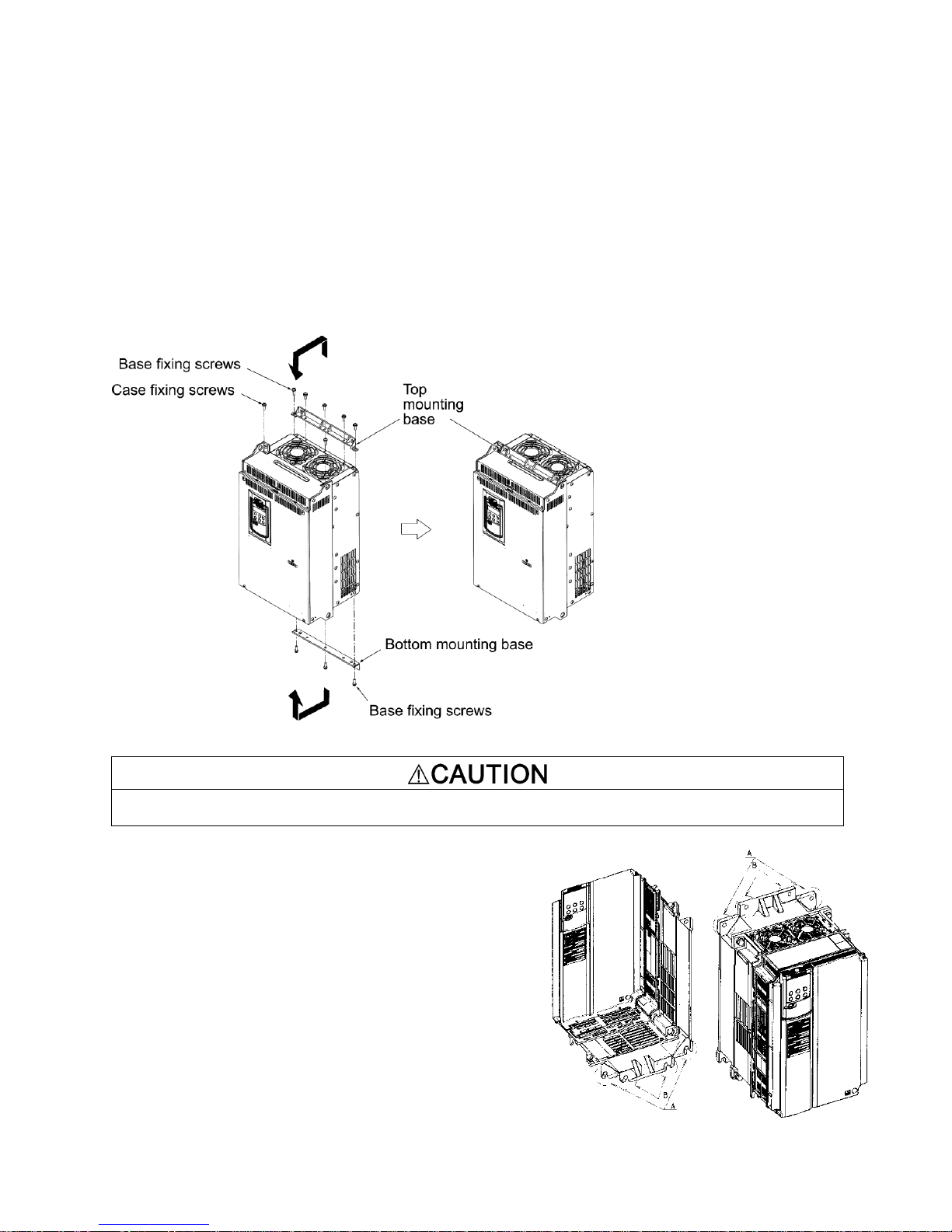
2. Mounting and Wiring
When changing the positions of the top and bottom mounting bases, use only the specified screws.
Otherwise, a fire or accident could occur.
2.1 Mounting Notes
Mounting the EQ7 in a control cabinet
1) Remove all base fixing screws and case fixing screws from the top of the inverter.
2) Move the top mounting base to the center of the inverter and secure it to the case fixing screw
holes with the base fixing screws. (After changing the position of the top mounting base, some
screws may be left unused.)
3) Remove all base fixing screws from the bottom of the inverter, move the bottom mounting base to
the center of the inverter, and secure it with the base fixing screws, just as in step 2). (Inverters of
450 HP or below have no case fixing screws on the bottom.)
Figure 2.1: Changing the Positions of the Top and Bottom Mounting Bases
(4) Mounting notes
Refer to the EQ7 Instruction Manual Chapter 2 for detailed
mounting Information.
The EQ7-2007-C / EQ7-4007-C through EQ7-2040-C / EQ74040-C should be mounted with four screws or bolts using
screw holes A or B shown below. Note that, at each of the top
and bottom of the inverter, the two screws or bolts should be
located in a bilaterally symmetrical position.
4
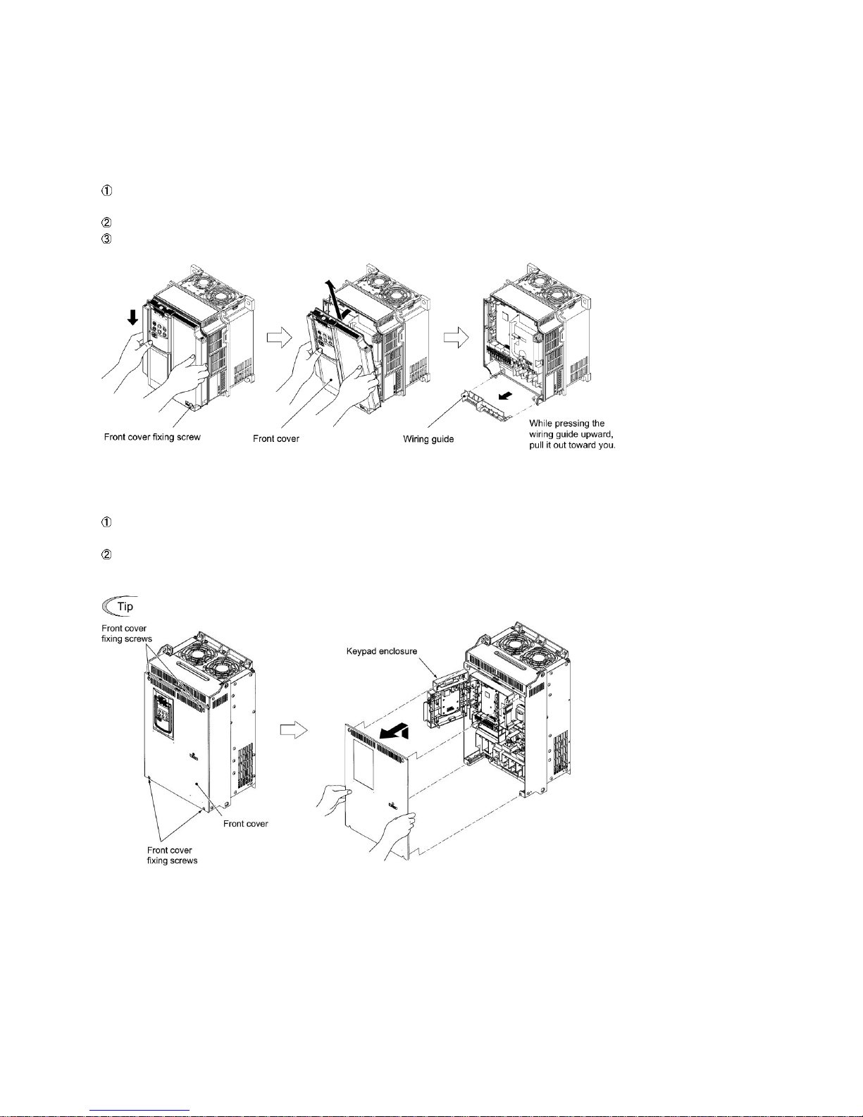
2.2 Wiring
To expose the control printed circuit board (control PCB), open the keypad enclosure.
Follow the procedure below. (In the following description, the inverter has already been installed.)
Removing and mounting the front cover and the wiring guide
(1) For inverters of 40 HP or below
First loosen the front cover fixing screw, slide the cover downward holding both sides, tilt it
forward, and then pull it upward, as shown below.
While pressing the wiring guide upward, pull it out and forward.
After carrying out wiring (see Section 2.3 of the EQ7 Instruction Manual), put the wiring guide
and the front cover back into place in the reverse order of removal.
Figure 2.2: Removing the Front Cover and the Wiring Guide (e.g EQ7-4020-C)
(2) For inverters of 50 to 1000 HP
Loosen the four front cover fixing screws, hold the cover with both hands, slide it upward
slightly, and pull it forward, as shown below.
After carrying out wiring (see Section 2.3 of the EQ7 Instruction Manual), align the screw
holes provided in the front cover with the screws on the inverter case, and then put the front cover
back into place in the reverse order of removal.
Tightening torque: 15.9 lb-in (1.8 Nm) (M4)
31.0 lb-in (3.5 Nm) (M5)
Figure 2.3: Removing the Front Cover (e.g. EQ7-4050-C)
5
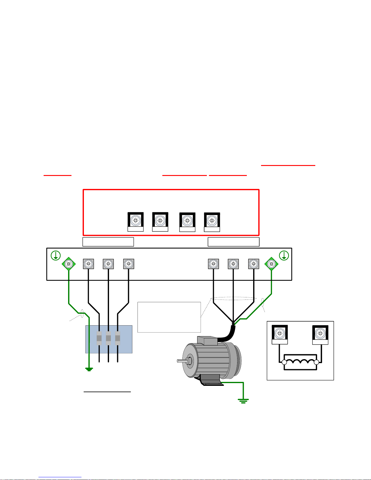
3. Input Power and Motor Connection
MOTOR
U V W
3Ø Induction
motor
Use L1, L2, L3 for
3Ø Input Power
Connect
frame to
ground
Input
Protection
(Fuse or Magnetic
Contactor)
To change direction of
motor rotation swap any
two of the three motor
leads.
L1
L2
L3
(R/L1)
(S/L2)
(T/L3)
(U/T1)
(V/T2)
(W/T3)
Ground
Use L1 & L3 for
1Ø Input Power
Ground
2
INPUT POWER
L1/R L2/S L3/T
P1
P(+)
N(-)
DB
WARNING DO NOT CONNECT ANY OF THE
FOLLOWING TERMINALS TO EARTH GROUND
Fig. 3.1
GND GND
*1 *1
*
DCR
P(+)
P1
EQ7
Checking prior to applying power
Fig.3.1 below shows the electrical connections for the input power and motor terminals for various
EQ7 DRIVE models. Verify the input power and motor terminals of the model you are installing. WITH
POWER OFF, make the appropriate connections.
Make sure to follow good wiring practices and all applicable codes. Ensure
that the equipment is grounded properly as shown.
DANGER, LETHAL VOLTAGES ARE PRESENT- Before applying power to the
EQ7 drive, ensure that the terminal cover is fastened and all wiring
connections are secure. After the power has been turned OFF, wait at least ten
minutes until the charge indicator extinguishes completely before touching
any wiring, circuit boards or components.
6
*1. Refer to page 12 & 13 for connecting a DC reactor from the terminals P1 and P(+).
*2. Make sure the drive is properly sized for single phase input (consult factory).
(Refer to Table 2.6 Recommended Wire Sizes in the EQ7 Instruction Manual).

Never connect power supply wires to the EQ7 drive output terminals U, V, and W. Doing so and turning
the power ON damages the inverter.
Be sure to connect the grounding wires of the EQ7 drive and the motor to the ground electrodes.
Otherwise, an electric shock could occur.
Check the following before powering on the EQ7 drive.
1) Check that the wiring is correct. In particular check the wiring to the EQ7 drive input terminals
L1/R, L2/S and L3/T and output terminals U, V, and W. Also check that the grounding wires are
connected to the grounding terminals ( G) correctly. See Figure 3.1.
2) Check the control circuit terminals and main circuit terminals for short circuits or ground faults.
3) Check for loose terminals, connectors and screws.
4) Check that the motor is separated from mechanical equipment.
5) Make sure that all switches of devices connected to the inverter are turned OFF. Powering on
the inverter with any of those switches being ON may cause an unexpected motor operation.
6) Check that safety measures are taken against runaway of the equipment. Also ensure that all
safety guards are in place to prevent human injury.
7
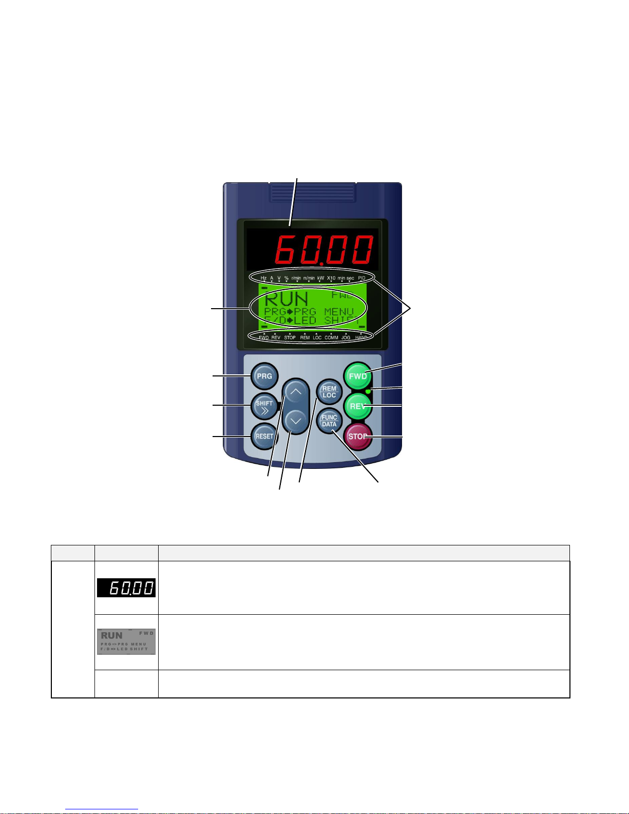
4. LED Monitor, LCD Monitor and Keys
Item
Monitor
Functions
Monitors
Five-digit, 7-segment LED monitor which displays the following according to the operation modes:
In Run mode: Running status information (e.g., output frequency, current, and voltage).
In Programming mode: Same as above.
In Alarm mode: Alarm code, which identifies the alarm when the protective function is activated.
LCD monitor which displays the following according to the operation modes:
In Run mode: Running status information.
In Programming mode: Menus, function codes and their settings.
In Alarm mode: Alarm code, which identifies the alarm when the protective function is activated.
Indication
Units
In Run mode, these show the unit for the number displayed on the 7-segment LED monitor and
the running status information on the LCD monitor. For details, see the next page.
7-segment LED Monitor
Program
Indication units
STOP key
RUN key (forward)
RUN key (reverse)
Reset key
Shift key
LED light
LCD monitor
DOWN key
UP key
Function/Data key
Remote/Local key
The keypad allows you to start and stop the motor, view various data including maintenance
information and alarm information, configure function codes, monitor I/O signal status, copy data, and
calculate the load factor.
Table 4.1: Overview of Keypad Functions
8
 Loading...