

Page 1
For warranty information, refer to:
http://www.cisco-servicefinder.com/WarrantyFinder.aspx
3 Safety Instructions
Translated versions of the following safety warnings are provided in Cisco USC 9330
Regulatory Compliance and Safety Information, located on Cisco.com.
Warning
Warning
Warning
Warning
IMPORTANT SAFETY INSTRUCTIONS
This warning symbol means danger. You are in a situation that could
cause bodily injury. Before you work on any equipment, be aware of the
hazards involved with electrical circuitry and be familiar with standard
practices for preventing accidents. Use the statement number provided
at the end of each warning to locate its translation in the translated
safety warnings that accompanied this device.
Statement 1071
SAVE THESE INSTRUCTIONS
Read the installation instructions before you connect the system to its
power source.
Statement 1004
Installation of the equipment must comply with local and national
electrical codes.
Statement 1074
In order to comply with FCC radio frequency (RF) exposure limits,
antennas should be located at a minimum of 7.9 inches (20 cm) or more
from the body of all persons.
Statement 332
USC 9330 QUICK START CARD
1 Connect Your Small Cell
Note Refer to the USC 9330 Installation Guide online for information
regarding the optimal placement of your USC 9330 small cell.
Follow these instructions to connect your USC 9330 for use:
Note Use only with listed ITE equipment.
Cisco Systems, Inc.
www.cisco.com
Cisco has more than 200 offices worldwide. Addresses, phone numbers, and fax numbers are listed on the
Cisco website at www.cisco.com/go/offices.
Cisco and the Cisco logo are trademarks or registered trademarks of Cisco and/or its affiliates in the U.S. and other countries. To view a list of Cisco trademarks,
go to this URL: www.cisco.com/go/trademarks. Third-party trademarks mentioned are the property of their respective owners. The use of the word partner does
not imply a partnership relationship between Cisco and any other company. (1110R)
© <year> Cisco Systems, Inc. All rights reserved.
Printed in the USA on recycled paper containing 10% postconsumer waste.
78-xxxxx-xx
Step 1 Screw the two antennas into the antenna ports on the top of the
small cell: Ant1 port=3G antenna, Ant2 port=2G antenna.
Step 2 Seal the antenna ports with waterproof glue or tape to prevent
any moisture from penetrating.
Step 3 Mount the USC 9330 small cell on a wall, ceiling or pipe as
described in the USC
9330 Installation Guide:
http://www.cisco.com/en/US/docs/wireless/...
Step 4 If you are using the DC power option:
a. Remove the connector cap from the DC power connector.
b. Connect the DC cable to the DC power connector on the
9330.
USC
Page 2
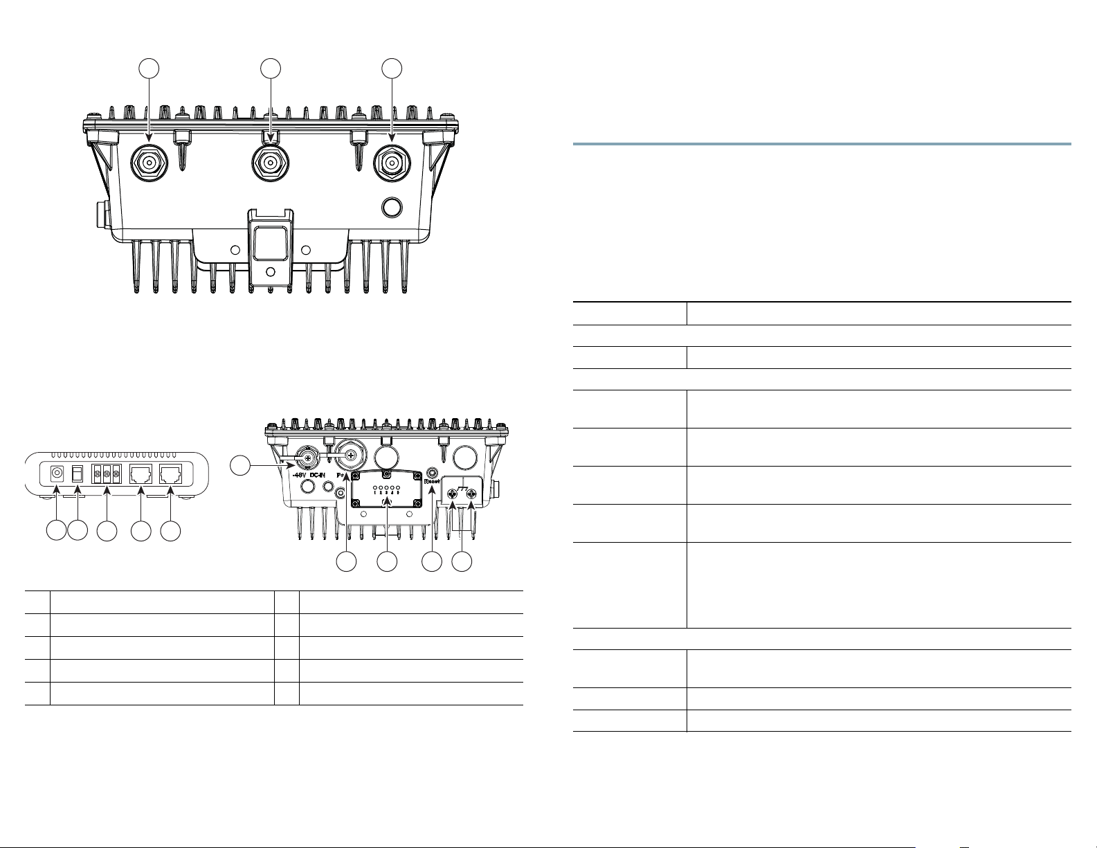
Figure 1USC 9330 Antenna Ports
Ant 2
GPS
Ant 1
1 2 3
382244
6
98710
1 2
3 4 5
382089
d. Connect the other end of the Ethernet cable to the PoE port on the PSE.
e. Connect the WAN port on the PSE to the Internet.
Step 6 Connect two grounding wires to the grounding screws on the USC 9330.
Step 7 Flip the power switch on the PSE to the appropriate location (1 for DC
power and 0 for PoE). The LED on the top of the PSE unit indicates the
power mode: Green: PoE; Blue: DC power.
2 Verify that the USC 9330 is Operational
The LED display is located on the bottom of your USC 9330. Note the color and
activity of the LEDs and refer to this table to diagnose any problems:
Ta b l e 1 USC 9330 Status LED Indications
c. Seal the DC power connector with waterproof glue or tape.
d. Connect the black end of the DC cable to the block 1 (0) power output of
the PSE and connect the red end of the DC cable to the block 2 (-48) power
output of the PSE.
Figure 2PSE and USC 9330 Connections
PSE 48V DC input
1
PSE power source selector switch
2
PSE terminal block
3
PSE PoE RJ45 connector
4
PSE WAN Ethernet connector
5
Step 5 If you are using the power over Ethernet (PoE) option:
a. Remove the connector cap from the Ethernet connector.
b. Connect the Ethernet cable to the Ethernet connector on the USC 9330.
c. Seal the Ethernet connector with waterproof glue or tape.
USC 9330 DC power connector
6
USC 9330 RJ45 connector
7
USC 9330 LED display
8
USC 9330 reset button
9
USC 9330 grounding screws
10
LED Indication Small Cell State / Action
Power LED (1)
Green Power is supplied to the unit.
Status LED (2)
Red blink 1 time
in 4 seconds
Red blink 2 times
in 4 seconds
Red blink 3 times
in 4 seconds
Red blink 4 times
in 4 seconds
Red Initial boot—wait up to 20 minutes; if still red, perform a reset
Service LED (3)
Fast Green Initialization or provisioning—Wait for action to complete
Green In service, no calls or data sessions—ready to support calls
Slow Green In service with active calls or data sessions
If you require assistance installing or operating your small cell, contact customer
support.
No electrical connection with residential gateway. Verify
connection and verify that the residential gateway is operational
No Internet connection—Verify that the residential gateway is
connected to the Internet and is providing service
Local interference—phones may be too close to your small cell.
If this problem persists, contact customer support.
Overheating—verify that the small cell is located where there is
proper air flow
Internal fault—Contact customer support
Excessive interference—Verify whether another small cell is
located in close proximity and if so, relocate unit
Provisioning failure—Contact customer support
Factory reset—Wait up to 20 minutes for action to complete
Page 3

FCC Regulations:
This device complies with part 15 of the FCC Rules. Operation is subject to the following two conditions: (1)
This device may not cause harmful interference, and (2) this device must accept any interference received,
including interference that may cause undesired operation.
Changes or modifications not expressly approved by the party responsible for compliance coul d void the user‘s
authority to operate the equipment.
****************************************************************************************************************************
This equipment has been tested and found to comply with the limits for a Class B digital device, pursuant to
part 15 of the FCC Rules. These limits are designed to provide reasonable protection against harmful
interference in a residential installation. This equipment generates, uses and can radiate radio frequency
energy and, if not installed and used in accordance with the instructions, may cause harmful interference to
radio communications. However, there is no guarantee that interference will not occur in a particular installation.
If this equipment does cause harmful interference to radio or television reception, which can be determined by
turning the equipment off and on, the user is encouraged to try to correct the interference by one or more of the
following measures:
—Reorient or relocate the receiving antenna.
—Increase the separation between the equipment and receiver.
—Connect the equipment into an outlet on a circuit different from that to which the receiver is connected.
—Consult the dealer or an experienced radio/TV technician for help.
****************************************************************************************************************************
FCC RF Exposure Information
This equipment complies with radio frequency (RF) exposure limits adopted by the Federal Communications
Commission for an uncontrolled environment. This equipment should be installed and operated with minimum
distance 20 cm between the radiator & your body.
****************************************************************************************************************************
 Loading...