

Page 1
KRD 901 54 Quick Installation Guide
Home Base Station 2
Mobile@Home
Page 2

Federal Communication Commission Interference Statement
This equipment has been tested and found to comply with the limits for a Class B
digital device, pursuant to Part 15 of the FCC Rules. These limits are designed to
provide reasonable protection against harmful interference in a residential installation.
This equipment generates, uses and can radiate radio frequency energy and, if not
installed and used in accordance with the instructions, may cause harmful interference
to radio communications. However, there is no guarantee that interference will not
occur in a particular installation. If this equipment does cause harmful ference to radio
or television reception, which can be determined by turning the equipment off and on,
the is encouraged to try to correct the interference by one of the following measures:
.Reorient or relocate the receiving antenna.
.Increase the separation between the equipment and receiver.
.Connect the equipment into an outlet on a circuit different from that to which the
receiver is connected.
.Consult the dealer or an experienced radio/TV technician for help.
FCC Caution :To assure continued compliance, any changes or modifications not expressly
approved by the party responsible for compliance could void the user's authority to operate this
equipment. (Example - use only shielded interface cables when connecting to computer or peripheral
devices).
FCC Radiation Exposure Statement
This equipment complies with FCC RF radiation exposure limits set forth for an
uncontrolled environment. This equipment should be installed and operated with a
minimum distance of 20 centimeters between the radiator and your body.
The antenna(s) used for this transmitter must not be co-located or operating in
conjunction with any other antenna or transmitter. No change to the antenna or the
device is permitted. Any change to the antenna or the device could result in the device
exceeding the RF exposure requirements and void user’s authority to operate the
device.
This device complies with Part 15 of the FCC Rules. Operation is subject to the
following two conditions:
(1) This device may not cause harmful interference, and (2) This device must accept
any interference received, including interference that may cause undesired operation.
Page 3
Disclaimer
The contents of this document are subject to revision without notice due to continued progress in methodology, design, and manufacturing. Ericsson shall have no
liability for any error or damage of any kind resulting from the use of this
document.
Introduction
This guide describes briefly how to install the KRD 901 54 access point (AP) and how to
pair/bond this to the Mobile Phone.
KRD 901 54 Installation
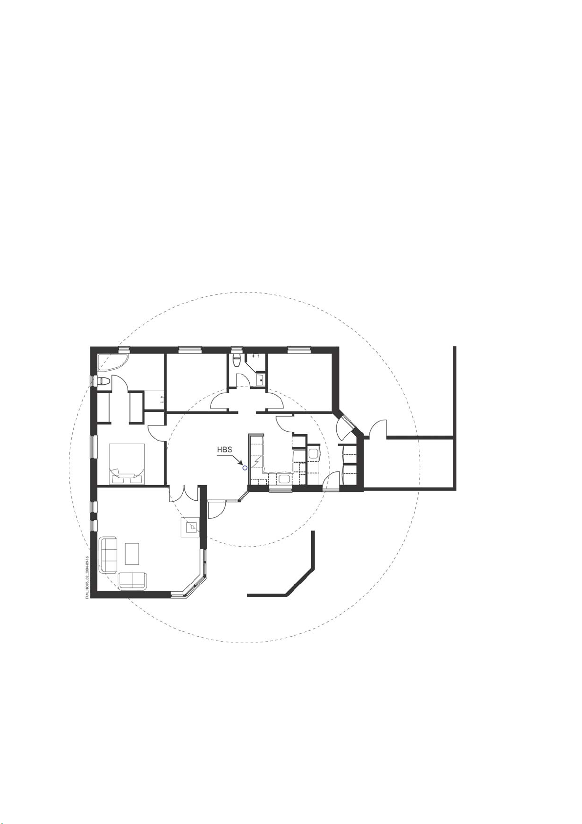
It is recommended to place the KRD 901 54 as centrally as possible in the area to give
coverage; see Figure 1. A height of at least 1 meter above floor level is advised.
Figure 1 Example on centrally placement of KRD 901 54 in the home;
circles indicate distance to the KRD 901 54
The KRD 901 54 can be placed on the wall; see Figure 2 or standing on a desk, shelf or
the like; see Figure 3.
In principle the KRD 901 54 may be placed where desired, although, to get the best
coverage, it is recommended not to place the KRD 901 54 close to metallic objects, as
2
Page 4

they will influence the transmitted signals. Usually the antenna is recommended to
point vertically.
Figure 2 Wall mount. Front view to the left. Bottom view to the right.
The Screw holes are 80 mm apart
Figure 3 Desk and shelf placement
3
Page 5
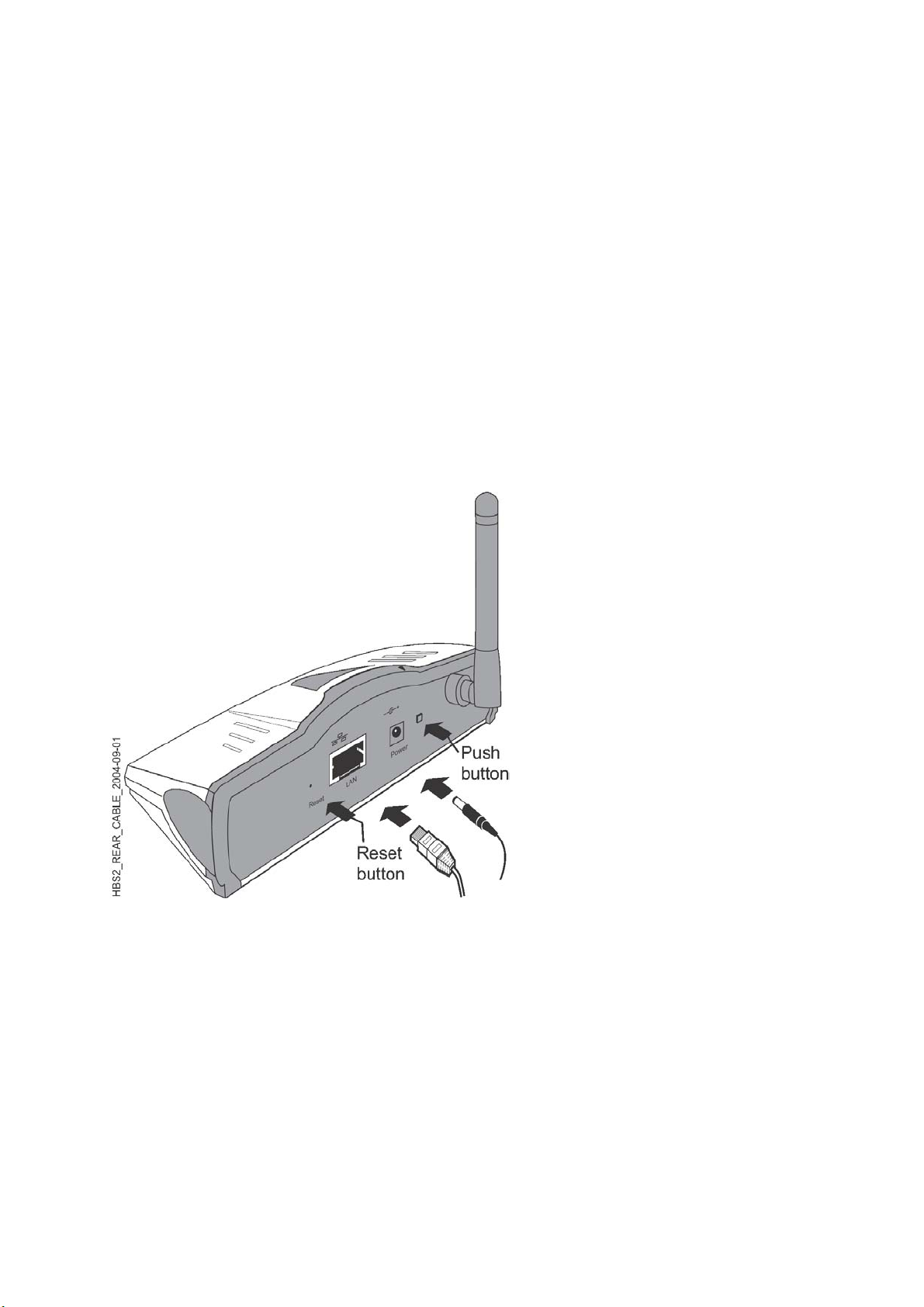
Cabling of Power Connections
To connect the KRD 901 54 the power adapter enclosed is to be used. If Power over
Ethernet is available this may be used instead of powering via the power adapter
cable. The power cable and the Ethernet cable to the IP Access Network shall be
connected as shown in Figure 4 below.
Buttons on rear panel of KRD 901 54
On the rear panel a push-button is placed. Pressing the button once will start the
member pairing sequence. Pressing the button twice (like a double click using a
“mouse”) will start the guest pairing sequence (i.e. being a guest at the premises
of another “Member”). See Figure 4.
Also a Reset function can be activated from the rear panel by using a thin pointy
device for at least 3 seconds. Activating the reset button will set the KRD 901 54 up to
the factory default settings; i.e. the PIN code and clearing the pairing list. See
Figure 4.
Figure 4 Cable connections
4
Page 6

LED indications of KRD 901 54
On the front of the KRD 901 54 four Light Emitting Diodes (LEDs) are situated. The LEDs
gives indications as described in the Table 1 below.
The LEDs labeled Member and Guest are only used in relation to the pairing
sequence and will be turned off after a short time. Pairing mode lasts 2 minutes
from the pairing button is pressed.
Table 1 Various LED indications on the KRD 901 54
LED state User action State Status Member Guest
Restart - KRD 901 54 is connecting ▌▌▌▌▌
Idle - Idle █████
Traffic - Traffic ongoing █ █ █
Member Pairing Single push Prepare KRD 901 54 for private pairing #) ▌▌▌▌▌
Guest pairing Double push Prepare KRD 901 54 for guest pairing #) ▌▌▌▌▌
Pairing Success - █████ █████
Pairing Failure - █████ █████
Fatal Failure
Reset to Factory
default settings
███ = Steady; ▌▌= Flashing Fast; █ █ = Flashing Slowly
§)
indication is seen briefly and a reboot will begin shortly after
The LED marked “LAN” indicates the activity on the LAN connection by blinking or steady green light.
#
) A quick single push on the “Push button” (see Figure 5) on the rear panel aborts an ongoing pairing
sequence.
§)
- Failure in KRD 901 54 █████
Push Reset button for
more than 3 seconds
Resets all parameters to factory default
settings
▌▌▌▌▌ ▌▌▌▌▌ ▌▌▌▌▌
█ = red
█ = green
Figure 5 Front panel of the KRD 901 54
5
Page 7
Registering a Mobile Phone to the KRD 901 54 – Pairing
In order to make the first call through the KRD 901 54, the Mobile Phone has to be
registered to the KRD 901 54 – the so-called pairing or bonding.
After a reset i.e. activation of the Reset button, it is necessary to redo the pairing.
The Mobile Phone must be Bluetooth enabled.
Please refer to instructions regarding “Bluetooth wireless” in the user’s
guide of the actual Mobile Phone in use.
Pairing can take place in two cases. Member pairing is a permanent pairing to the
KRD 901 54 access point in the premises where the Mobile@Home solution is installed.
Guest pairing is a temporary pairing a Mobile Phone to the KRD 901 54 access point e.g.
during a visit in a premises of another owner (“Member”). The guest pairing information is removed from the pairing list 24 hours after the last call was completed.
Member pairing
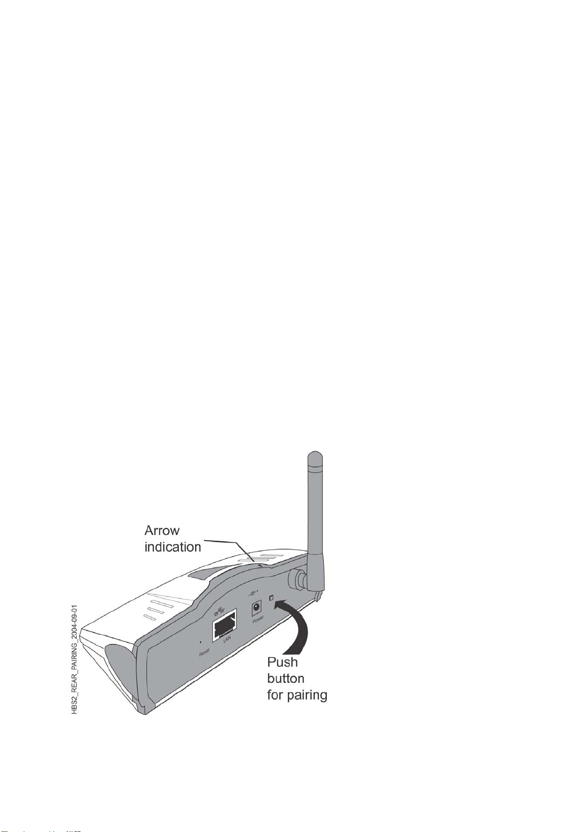
Prepare the KRD 901 54 for Member pairing by pushing the button (Pairing button) on
the rear panel of the KRD 901 54 once; see Figure 6.
The Member LED will flash fast green.
or
Guest pairing
Prepare the KRD 901 54 for Guest pairing by double pushing the button (Pairing button)
on the rear panel of the KRD 901 54; see Figure 6.
The Guest LED will flash fast green. Guest pairing is pairing a Mobile Phone when
visiting “another” home with an KRD 901 54 access point (AP).
Figure 6 Press the Pairing button once for Member pairing
and twice for Guest pairing
6
Page 8

Bluetooth devices that are located within the range of the Mobile Phone will be
listed in the display. KRD 901 54 devices are identified by their Bluetooth Device
Address that can also be found on the bar code label (BDA). The information
displayed in the list is vendor dependant.
Depending on the service provider a PIN code may be requested for security
reasons. This will be prompted for in the display. Enter the assigned PIN code (up
to 16 digits; factory default setting is 4 digits) and press the “Send key”/“Yes” key.
In the display of the Mobile Phone a Bluetooth symbol
a Bluetooth link is established between the Mobile Phone and the KRD 901 54.
Disclaimer: Depending on the Bluetooth capabilities of the Mobile Phone the
Mobile@Home link may not co-exist with a Bluetooth headset link.
If more Mobile Phones have to be paired to the KRD 901 54, please repeat the above
pairing procedure.
Note: The pairing must be done within 2 minutes after the pairing button has
been pushed (Figure 6).
will appear, indicating that
Troubleshooting
In Case of a troublesome situation is supposed, check the following:
- if none of the LEDs are lit, check if the power cable is connected or the Power
over Ethernet is working satisfactory.
- if neither of the Member or Guest LEDs are lit steady green for a short while
after the pairing session has terminated, redo the pairing sequence.
- if no connection is established through the KRD 901 54, i.e. the LAN LED is giving no
indication, check if the LAN cable is connected correctly to both the KRD 901 54 and
the IP Access Network terminal.
- if an unforeseen and troublesome situation should arise, either unplug the
power connector for approx. 10 sec. and reconnect, or remove the Ethernet
cable (if powered over Ethernet).
Technical data
Dimensions (h x w x d) 41 x 137 x 128 [mm]; antenna may add from 65 to
87 mm to “h” or “d” depending on direction
Weight 215 g (Power adaptor excluded)
Number of paired devices 10
AD/DC adaptor:
- market variants USA/Canada, UK, Europe, China
- input 100 to 240 VAC; 50/60 Hz; 0,5A
- output 24 VDC; 0,3A
- power < 5 W
LAN interface 10/100 BaseT
Quality of Service supports DiffServ
HTTP-server WEB access for local management
7
Page 9

Ericsson Telecom AB 1/1531-FGC 101 752/1 Uen PA4
www.ericsson.com
8
Ericsson AB 2004
 Loading...