

Page 1

GW6200
USER’S MANUAL
Copyright © 2008 by TECOM CO. LTD.
Page 2

GW6200 Product Spec Table of Contents
Table of Contents
1. Introduction ..................................................................................................................... 3
2. Getting to Know the Router............................................................................................. 5
2.1 Specifications...........................................................................................................................................................5
2.2 Front Panel...............................................................................................................................................................5
2.3 Rear Panel................................................................................................................................................................6
3. System Features............................................................................................................. 7
3.1 Answering Position ..................................................................................................................................................7
3.2 Auto Attendant & Voice Mail...................................................................................................................................7
3.3 Basic Call.................................................................................................................................................................8
3.4 Call Abandon............................................................................................................................................................8
3.5 Call Operator (Call Attendant).................................................................................................................................8
3.6 Call Routing.............................................................................................................................................................8
3.7 Caller ID...................................................................................................................................................................8
3.8 Class Of Service (COS) ...........................................................................................................................................8
3.9 Daylight Saving Time ..............................................................................................................................................9
3.10 Direct Inward System Access (DISA) via Auto Attendant.....................................................................................9
3.11 Dynamic DNS........................................................................................................................................................9
3.12 Extension Password ...............................................................................................................................................9
3.13 Fax/Modem............................................................................................................................................................9
3.14 Flash - Analog Port (SLT) Flash Recognition........................................................................................................9
3.15 Hunt Group ............................................................................................................................................................9
3.16 IG Expansion..........................................................................................................................................................9
3.17 IP Trunk..................................................................................................................................................................9
3.18 Make an Outside Call...........................................................................................................................................10
3.19 Message Waiting Indication.................................................................................................................................10
3.20 Music On Hold.....................................................................................................................................................10
3.21 Night Switching ...................................................................................................................................................10
3.22 Numbering Plan ...................................................................................................................................................10
3.23 Paging(All/Group)................................................................................................................................................10
3.24 PSTN Backup.......................................................................................................................................................10
3.25 Registration..........................................................................................................................................................10
3.26 Remote Management via PC................................................................................................................................11
3.27 System Speed Dial ...............................................................................................................................................11
3.28 System Time & Date............................................................................................................................................11
3.29 Toll Restriction..................................................................................................................................................... 11
3.30 Transfer................................................................................................................................................................11
3.31 Trunk Group.........................................................................................................................................................11
3.32 Web Access Control.............................................................................................................................................11
3.33 Wizard Setup........................................................................................................................................................12
Appendix : Product Summary............................................................................................ 14
Copy Right 2008 Tecom, Co. LTD. All rights reserved Page 2 of 2
Page 3
GW6200 Product Spec Introduction
ADSL Modem
1. Introduction
Congratulate on becoming the owner of the GW6200.Your LAN (local area network) and
WAN (wide area network) will now be able to access the Internet using your high-speed
Ethernet connection. This Administrator Manual will show you how to install and set up
your GW6200.
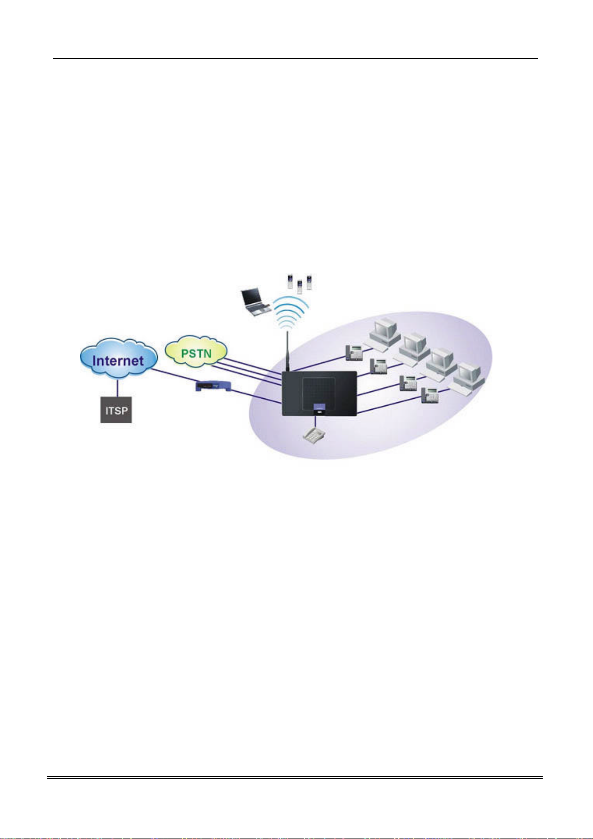
The IG (Intelligent Gateway) provides a variety of functions for users and can support a
wide range of application in a complicated environment. Therefore, it needs
Administrator to plan, install and set the whole environment of VoIP communication. And
the knowledge of modern network and Internet technologies are essential for
administrator.
WiFi Phone
Notebook
Interfaces
l WAN Interface: 10/100Base-T Ethernet port
l CO Interface: 3 FXO (Loop Start, for PSTN)
l Analog Device Interface: 1 FXS (for analog Telephone or FAX)
l LAN Interface: 4 Ethernet (10/100Base-T)
l Built-in 802.11g Wi-Fi access point
Terminals
l 1 Analog Terminal
l 24 IP Stations (Wired/Wi-Fi IP Phone)
/ Cable Modem
Router Connection Diagram
PC
Analog Phone
In principle, the Administration is required to do the following things:
(1) To understand the architecture, resources, and devices of whole environment
which will be involved with the VoIP communications.
(2) To build a common setting file for most users.
Copy Right 2008 Tecom, Co. LTD. All rights reserved Page 3 of 3
Page 4

GW6200 Product Spec Introduction
(3) To configure each phone and install them into the network.
(4) To configure each interfaces and install them into IG.
(5) And to solve the problems what users encounter during operation.
Copy Right 2008 Tecom, Co. LTD. All rights reserved Page 4 of 4
Page 5
GW6200 Product Spec Installation
2. Getting to Know the Router
2.1 Specifications
Feature Additional Info
Main Processor 240MHZ MIPS32 CPU
Processor SDRAM External 64MB
Processor Flash ROM External 8 MB
Supplementary Processor 1x DSP AudioCode AC482-C (4 channel/each)
System Flash (Voice Mail) 128MB
Switch controller Broadcom BCM5325E
System Power: 15V/0.8A
Standards IEEE802.11g,IEEE802.11b,IEEE802.3
Ports
Button Reset, Power on/off
Cabling RJ-45,RJ-11
LEDs
EMI/EMC: FCC Part15&68 ClassB / CE Certificated
Environmental
1× WAN, 4× LAN, 1× FXS , 3× FXO
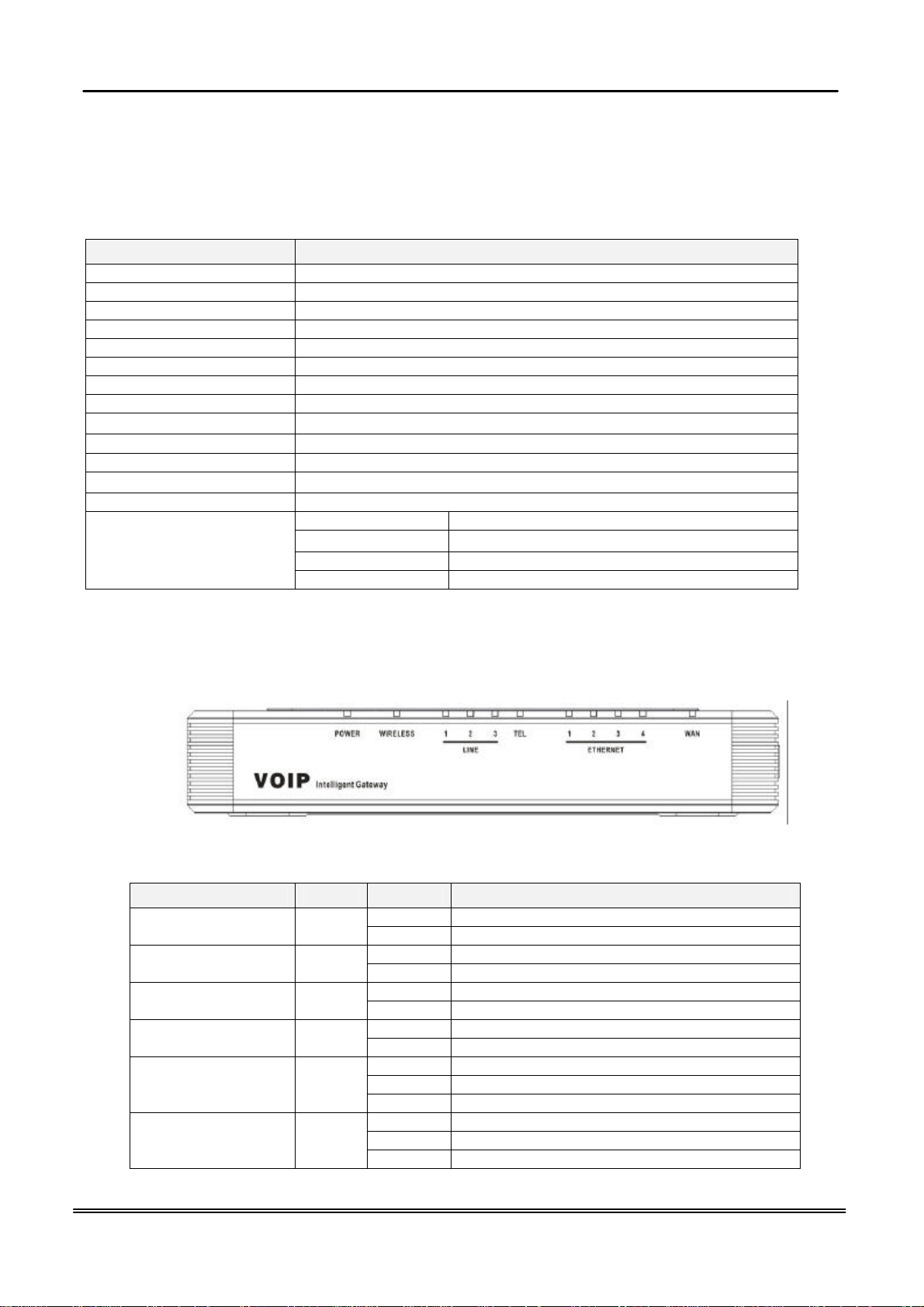
POWER, WIRELESS, 3× LINE, TEL, 4× ETHERNET, WAN
Operating Temp .0ºC to40ºC (32ºF to 104ºF)
Storage Temp. -20ºC to 70ºC (-4ºF to 158ºF)
Operating Humidity 10% to 80% relative humidity, Non-Condensing
Storage Humidity 10% to 90% Non-Condensing
2.2 Front Panel
The front panel contains several LEDs that indicate the status of the unit.
Figure 2-1. Front Panel of GW6200
LED Name Color
ETHERNET(1-4) Blue
INTERNET Blue
Status Description
On Power on. POWER Blue
Off Power off.
On Wireless LAN initialization success. WIRELESS Blue
Off Wireless LAN is not present.
Off PSTN Line is idle. LINE (1-3) Blue
On PSTN Line is busy.
Off Phone is idle. TEL Blue
On Phone is busy.
On LAN connected.
Off LAN network connection not present.
Flashing LAN activity present (traffic in either direction).
On WAN connected.
Off WAN network connection not present.
Flashing WAN activity present (traffic in either direction).
Copy Right 2008 Tecom, Co. LTD. All rights reserved Page 5 of 5
Page 6

GW6200 Product Spec Installation
2.3 Rear Panel
The rear panel contains the ports for the unit's data and power connections.
Figure 2-2. Rear Panel of GW6200
Label Function
WAN RJ-45 connector: Connects the device to your cable modem, or to your
ADSL Modem, It’s to connect to the remote network
LAN1-4 RJ-45 connector: Connects the device to your PC's Ethernet port, or to
the uplink port on your LAN's hub,
TEL1 RJ-11 connector: Connects the device to your analog phone,
Line 1-3 RJ-11 connector: Connects the device to your PSTN lines
Power Connects to the supplied power converter cable
On/Off Switches the device on and off
Copy Right 2008 Tecom, Co. LTD. All rights reserved Page 6 of 6
Page 7

GW6200 Product Spec System Features
3. System Features
3.1 Answering Position
For incoming calls from PSTN (FXO ports), system provides the flexibility to ring to
different destinations: Auto Attendant, Operator or Extension, according to the system
service mode (day or night modes). For Extension, system provides the ability to have
the calls to ring to one extension or one hunt group.
It is also for those incoming VoIP calls from the registered ISP (Uplink Server) to be
routed with the same method.
3.2 Auto Attendant & Voice Mail
The IG Auto Attendant can greatly enhance business office productivity by providing
either a full-duty automated attendant to handle all incoming system calls or part-duty
automated attendant to handle overflow traffic.
The Automated Attendant & Voice Mail Module provides 128MB of programmable voice
announcements. It provides four ports to handle four (4) simultaneous callers. It
provides the following functions:
l Auto Attendant Functions
It provides an incoming caller with a customized welcome greeting that
describes the actions available to an incoming caller:
n Provide four kinds of main greeting messages: Day, Night, Noon,
and Holiday greeting messages.
n Dial an extension number or operator code to reach the appreciate
destination.
n Press a digit to leave a message in a particular mailbox.
n Press a digit to make an outside call via the specified check.
n Provide the phone to forward the call to its voicemail box.
n Provide the phone to set Direct Call Forward, Busy Call Forward or
No Answer Call Forward. It will forward the incoming trunk call to
another extension.
n Provide the phone to set Do Not Disturb to stop the incoming line call
from ringing.
l Voice Mail Functions
All mailbox users have access to these mailbox features
n Delete, save, or skip messages.
n Send messages to other mailbox.
n Receive message information indicating the date, time, and sender
information, if available.
n Change personal greeting, and password.
n Playback controls when reviewing messages.
n Record a temporary greeting.
n Send a notification via email when getting a leaving message.
n Add attached WAV file in notifying email for leaved message.
n The maximum recording length for each call is 180 seconds.
n The all extension users share the same VM size. If the all extensions
exist (25 extensions), the maximum total length for each user is about
10 minutes.
Copy Right 2005 Tecom, Co. LTD. All rights reserved Page 7 of 7
Page 8

GW6200 Product Spec System Features
n For each leaving message, it's saved 1 - 7 days
l Voice Messages
n Provide two languages service for the all voice files.
n Administrators can record the all voice messages by themselves.
n Administrators can update, backup or delete the all voice messages
on the PC.
3.3 Basic Call
To make an intercom call, dial a Station number (IP Terminal, POTS) or a Voice Mail
number.
To make an outgoing call, dial a phone number. System chooses a line (PSTN line, IP
trunk, another GW6200) via Call Routing Table to dial out. If it includes “*” in the phone
number, and the call is dialed through PSTN Trunk, it will be as a one second Pause
time.
To make an outgoing call, dial a PSTN, an IP Trunk or a Trunk Group number first. After
hearing dial tone, dial the phone number.
3.4 Call Abandon
For every PSTN call, system provides the facility (Loop Break, Polarity Reversal,
Release Tone) to monitor the call status. If the remote party hangs up, the ongoing call
must be terminated.
3.5 Call Operator (Call Attendant)
One primary operator may be assigned in the system. The standard IP phone will serve
as the operator telephone. When assigned as operator, this extension supports general
system functions.
While the internal extension dials Operator Directory Number ("0" at default), or the
outside party dials "0" when Auto Attendant plays the Welcome message, these calls
will be stored into Operator Queue. The Operator is First-In-First-Out to service these
calls. At the waiting time, the calling party will be on Music-On-Hold state.
3.6 Call Routing
The Call Routing feature automatically routes outgoing calls using the most appropriate
route. The appropriate route is determined based on the number dialed. If necessary,
GW6200 can automatically modify the dialed number by deleting and inserting digits.
The call routing destination is a PSTN line, an IP line, a line group or another GW6200.
3.7 Caller ID
GW6200 provides the ability to detect the calling party identification provided by CO via
PSTN lines or by Uplink Server via IP trunks. This data when received by the telephone
carrier will be displayed on all ringing IP phones or Caller ID equipped Single Line
Telephone.
3.8 Class Of Service (COS)
GW6200 provides eight (8) Classes of Service (COS) for assignment of outside line
dialing-privileges. Each extension may be assigned one Day-COS and one Night-COS.
The Extension COS is primarily used for restriction and control of long distance dialing.
COS 0 is the highest priority. COS 7 is the lowest one.
Copy Right 2008 Tecom, Co. LTD. All rights reserved Page 8 of 8
Page 9

GW6200 Product Spec System Features
3.9 Daylight Saving Time
Daylight Saving Time (DST) feature supports auto adjustment for daylight saving time.
3.10 Direct Inward System Access (DISA) via Auto Attendant
The current PSTN/IP lines are all DISA lines. While ringing to AA, the outside callers
have direct access to extensions, PSTN/IP lines, Call Routing and Trunk Groups.
3.11 Dynamic DNS
GW6200 support Dynamic DNS to see the DDNS host name as GW6200’s WAN IP
address in SIP application. Let the GW6200 have a static domain name for dynamic IP
address.
Before using the feature, you must register domains on DynDNS.org or TZO.
3.12 Extension Password
All extensions of the IG system have an associated User Password. Password length is
system programmable from 0 to 24 characters.
All extensions of the IG system also have an associated User Password. The Password
is applied to Voice Mail service, and some system feature settings (Phone Lock, COS
Following).
3.13 Fax/Modem
GW6200 supports FAX/modem tone detection and auto-fallback to G.711.
3.14 Flash - Analog Port (SLT) Flash Recognition
Flash is the momentary operation of the hook-switch at the analog device, which can be
deciphered by the IG system in such a way that the previous call in progress is held, or
placed in a status of transfer awaiting further instructions from the user.
3.15 Hunt Group
Incoming Trunk call can ring all Hunt Group member extensions simultaneously (All
Ring). GW6200 supports 4 Hunt Groups. Each Hunt Group can have up to 24 members.
Incoming Trunk calls ring all member extensions simultaneously. If more than one call
rings at the same time, the first agent to go off hook will be connected to the call that has
been ringing the longest.
For unanswered Trunk call, it will be forwarded to a Reroute destination. The Reroute
destination can be Auto Attendant or the first member’s Voice Mailbox.
3.16 IG Expansion
While dialing a number, it may route to another GW6200 through Call Routing Table. It
allows the user to make a direct call to an extension in another GW6200. It also allows
the user to share the PSTN or IP Trunks in another GW6200 to make an outside call.
3.17 IP Trunk
GW6200 can register up to 8 SIP Uplink Servers. The extensions may make a call to the
users of the Uplink Servers, or any user in the world through the Uplink Servers.
l SIP message, including INVITE, re-INVITE, ACK, CANCEL, OPTIONS, BYE,
Copy Right 2008 Tecom, Co. LTD. All rights reserved Page 9 of 9
Page 10

GW6200 Product Spec System Features
REGISTER, INFO, REFER, SUSCRIBE/NOTIFY and REPLACE messages.
l SIP Outbound Proxy, SIP Proxy and Registrar
l Auto-Registration when power-on or period
l Session Timer support
l Support IP address, domain name, user name, display name for SIP URL
l STUN
3.18 Make an Outside Call
System provides three methods to make an outside call.
l The extension user dials the phone number directly. System automatically
routes the outgoing call using the least expensive line via Call Routing Table.
l The extension user dials a Line number or a Line Group number first. After
hearing the dial tone, the user dials the phone number.
l The extension presses a Line key first. After hearing the dial tone, the user
dials the phone number.
3.19 Message Waiting Indication
It’s a Voice Mail feature. When somebody leave messages, the router will inform the
phones, and phones’ LCD will display new voice mails information, and its led will flash
accordingly.
3.20 Music On Hold
Any PSTN/IP line calls which placed on hold will give music to the other external party.
3.21 Night Switching
GW6200 provide Day and night settings in service mode page. And during different time,
Trunk incoming call will be forwarded to different extensions according to the settings.
3.22 Numbering Plan
The Numbering Plan refers to the structure of dialed access to the various resources
that are part of the system. GW6200 also allows for a very flexible configuration
numbering for the various system resources.
3.23 Paging(All/Group)
A Page can be initiated from any extension in the system. Dialing a Paging Group
Directory number allows an extension to broadcast a page to all assigned members of
the selected paging group.
3.24 PSTN Backup
In case of power failure, GW6200 automatically switches the first PSTN line to the
Single-line analog phone. The other PSTN lines are not supported.
3.25 Registration
The IG combines Proxy and Registrar servers in its application. For a Registrar server, it
acts as the front end to the location service for a domain, reading and writing mappings
based on the contents of REGISTER requests. The location service is then typically
consulted by a Proxy server.
Copy Right 2008 Tecom, Co. LTD. All rights reserved Page 10 of 10
Page 11

GW6200 Product Spec System Features
3.26 Remote Management via PC
Programming the IG system database is possible via PC. IG build-in a web server for
remote administration.
3.27 System Speed Dial
GW6200 stores frequently dialed numbers. These Speed Dial Numbers are accessed
for dialing by the associated Speed Dial Directory Numbers. The Speed Dial Directory
Numbers are assigned in Numbering Table.
GW6200 stores up to 100 Speed Dial Numbers. In the Speed Dial Number, it’s allowed
to store Phone number up to 20 digits in length. Call Restriction and Call Routing are
applied and extensions may utilize only those numbers allowed based on their extension
COS.
3.28 System Time & Date
The IG system provides a built-in time clock to track System Time for reference in
certain features such as System Night Service Mode Change. This clock has the ability
to automatically adjust with network NTP server through Internet.
3.29 Toll Restriction
GW6200 provides sophisticated monitoring of digits dialed on PSTN/IP Trunks. If a digit
or range of digits dialed on a Trunk line is inconsistent with the dialing extension’s COS,
the call is denied. This calling COS criteria can be applied to local calls, long distance
calls, and specific numbers that are considered allowed in areas where other numbers
may be restricted.
3.30 Transfer
Transfer is used to deliver calls at your extension to another extension. It means that
calls can be routed to IG system destinations: an extension or an outside phone number.
3.31 Trunk Group
System assigns each PSTN Trunk and IP Trunk to a specific Trunk Group. Each Trunk
can be assigned to only one Trunk Group. The Trunk group assignment is used for
Trunk pool access.
If setting some PSTN trunks and some IP trunks into the same Trunk Group, the trunk
access depends on the access priority.
System provides up to 4 Trunk Groups. All PSTN Trunks and IP Trunks are assigned to
default Trunk Group 1 and PSTN Trunks has higher access priority.
System provides up to 4 Trunk Groups. All PSTN Trunks are assigned to Trunk Group 1
and all IP Trunks are assigned to Trunk Group 2.
3.32 Web Access Control
It has System and Phone web access level.
l System’s Web Page Access Control
Allow only one user can login system’s Web page at the same time. One can’t login
system’s Web page when there is another user has login already until the user
logout or has no-action in 3 minutes.
Copy Right 2008 Tecom, Co. LTD. All rights reserved Page 11 of 11
Page 12

GW6200 Product Spec System Features
l IP Phone's Web Page Access Control
Allow the users access internal IP phone's Web page. There are two methods to
follow.
n Login system’s Web page. In “Registered Phone” Page, all registered phones
will be listed with their IP links. Click the link you can enter IP phone’s Web
page.
n Use voicemail username and password of IP phone when login system’s Web
page. It will give a page list all registered phones with their IP links.
3.33 Wizard Setup
Wizard Setup allows system administrator to select the appropriate mode and configure
the corresponding settings step by step to create a basic GW6200 operation.
The following eight operation setting items are supported
WAN Setting
LAN Setting
Wireless Basic
Wireless Security
Internet Time
Numbering Plan
IP Trunk
Call Routing Table
Copy Right 2008 Tecom, Co. LTD. All rights reserved Page 12 of 12
Page 13

GW6200 Product Spec Configuration
Copy Right 2005 Tecom, Co. LTD. All rights reserved Page 13 of 13
Page 14

GW6200 Product Spec Appendix
Appendix : Product Summary
TCP/IP Protocols
q IP Protocol (RFC 791)
q ARP (RFC 826) / RARP (RFC 903)
q ICMP (RFC792)
q TCP (RFC 793)
q UDP (RFC 768)
q SNTP
q DNS
q HTTP
q Telnet
q TFTP
q RTP
q Static Routing
q NAT with ALGs
IP Address Assignment
q Static
q Dynamic
q Subnet Mask
q PPPoE Client (RFC 2516)
q Primary and Secondary DNS
q DHCP Server (RFC 2131-2132)
q DHCP Client (RFC 2132)
Routing
q RIP v1/v2
q Static routing
q DHCP Server/Relay/Client
q DNS Relay
q NAT/NAPT
q IGMP Proxy
Virtual Server
q Virtual Server
q Port Trigger
QoS
q IP ToS function (RFC 1349)
q Priority queues for upstream traffic based on ToS field.
Copy Right 2005 Tecom, Co. LTD. All rights reserved Page 14 of 14
Page 15

GW6200 Product Spec Appendix
q IP Precedence
VoIP Protocols
q SIP (RFC 3261)
q SDP(RFC2327) t
q Real Time Protocol (RTP ; RFC 1889)
q MD5 (RFC3261 HTTP) digest authentication
q G.168 Echo Cancellation
q Voice Codec: G.711, G.729a and G.726
q Support FAX/modem tone detection and auto-fallback to G.711
IP Trunk
Support up to 8 IP Trunk, which can register to ITSP carrier.
q SIP message, including INVITE, re-INVITE, ACK, CANCEL, OPTIONS, BYE, REGISTER, INFO,
REFER, SUSCRIBE/NOTIFY and REPLACE messages.
q SIP Outbound Proxy, SIP Proxy and Registrar
q Auto-Registration when power-on or period
q Session Timer support
q Support IP address, domain name, user name, display name for SIP URL
Digital Audio
q Codec:
G.711 a-law/µ-law 64Kbps,
G.729A/B (8Kbps),
G.726
q SIP Call Offer /Answer: Codec auto capacity exchange
q Echo Cancellation: G.168 for each voice line
q Silence Detection/Suppression
q Comfort Noise Generation
q Adaptive jitter buffer
q Different frame size support (10,20,30,40, 50, and 60ms)
q Packet loss concealment
q Out-band (RFC2833) and In-band DTMF
Security
q Password protected system management
q User authentication for PPP (PAP/CHAP/MSCHAP)
q Firewall
q Packet Filtering
q Access Control List
q Wireless Security:
Support WEP (64, 128-bit) encryption
802.1x and WPA/WAP2 authentication
MAC Address-based access control
Copy Right 2008 Tecom, Co. LTD. All rights reserved Page 15 of 15
Page 16

GW6200 Product Spec Appendix
WDS support
Configuration Management
q LAN/WAN management via Telnet interface or Web-based browser interface
q Firmware upgrade available by HTTP
q Status display and event report from Web-based management
q Settings Save and Restore
q Reset to factory default
Radio - WLAN
q Stansard : IEEE 802.1g and 802.11b
q Media Access Control : CSMA/CA with ACK
q Modulation : OFDM/CCK
q Frequency Range (Range depends on different country)
q Output Power : 15dBm (typical)
q Sensitivity : -67 (54Mbps) / -83 (11Mbps) dBm (typical)
q Data Rate : 54, 48, 36, 24, 18, 12, 11, 6, 5.5, 2, 1Mbps, auto-fallback
Remote Diagnostic
q Syslog
q Device Diagnostic, Enable remote test following:
Test the connection to your local network,
The connection to your Internet service provider,
The status of PSTN Line,
The status of IP Trunk Line,
The status of VAA Line,
The status of FXS
The registered status of SIP Phones
Physical Interfaces
q One 10/100BaseT Internet port (RJ-45) for WAN interface
q Four 10/100BaseT Internet port (RJ-45) for LAN interface
q One Telephone interface (RJ-11)
q Three PSTN Line interface
q One PSTN Backup line
LED Status
LED Name Color Status Description
On Power on. POWER Blue
Off Power off.
On Wireless LAN initialization success. WIRELESS Blue
Off Wireless LAN is not present.
Off PSTN Line is idle. LINE (1-3) Blue
On PSTN Line is busy.
Off Phone is idle. TEL Blue
On Phone is busy.
ETHERNET(1-4) Blue On LAN connected.
Copy Right 2008 Tecom, Co. LTD. All rights reserved Page 16 of 16
Page 17

GW6200 Product Spec Appendix
the device.
Off LAN network connection not present.
Flashing LAN activity present (traffic in either direction).
INTERNET Blue On WAN connected.
Power Requirement
q Input : Voltage Range 120VAC/60HZ or 220VAC/50HZ
q Output : Linear 15V DC / 0.8A, 2.1mm barrel jack
Operating Environment
q Temperature : 0~40
q Humidity : 10 to 90%, non-condensing
0
C
Physical Specification
q Dimension : 192(W) x 280(L) x 32(D) (mm)
q Notice : The changes or modifications not expressly approved by the party
q
q responsible for compliance could void the user’s authority to operate the equipment.
q
q IMPORTANT NOTE: To comply with the FCC RF exposure compliance requirements,
q
q the antenna(s) used for this transmitter must be installed to provide a separation
q
q distance of at least 20 cm from all persons and must not be co-located or operating in
q
q conjunction with any other antenna or transmitter. No change to the antenna or the
q
q device is permitted. Any change to the antenna or the device could result in the
q
q device exceeding the RF exposure requirements and void user's authority to operate
q
q
q FCC INFORMATIONThe Federal Communication Commission Radio Frequency
InterferenceStatement includes the following paragraph:The equipment has been tested and found
to comply with the limits for a ClassB Digital Device, pursuant to part 15 of the FCC Rules. These
limits are designedto provide reasonable protection against harmful interference in a
residentialinstallation. This equipment generates, uses and can radiate radio frequencyenergy and,
if not installed and used in accordance with the instruction, may causeharmful interference to radio
communication. However, there is no grantee thatinterference will not occur in a particular
installation. If this equipment dose causeharmful interference to radio or television reception, which
can be determined by turning the equipment off and on , the user is encouraged to try to correct the
interference by one or more of the following measures:--Reorient or relocate the receiving
antenna.--Increase the separation between the equipment and receiver.--Connect the equipment
into an outlet on a circuit different from that to which the receiver is connected.--Consult the dealer
or an experienced radio/TV technician for help.The user should not modify or change this
equipment without written approvalform TECOM CO., LTD. Modification could void authority to use
this equipment.
Copy Right 2008 Tecom, Co. LTD. All rights reserved Page 17 of 17
 Loading...