

Tecomat TC600, TC601, TC603, TC604, TC602 Series Manual
...
Technical equipment of TC600 PLC
Contents
1. Abbreviations and Terms ...................................................................................................... 3
2. Description............................................................................................................................. 5
2.1 The Specification................................................................................................................. 5
2.2 Compatibility ........................................................................................................................ 5
2.3 Communication.................................................................................................................... 5
2.4 Di str ibuted Control ............................................................................................................... 5
2.5 The Building......................................................................................................................... 6
2.6 Design..................................................................................................................................7
3. Parameters Overview ............................................................................................................. 8
3.1 Basic P r oper ties................................................................................................................... 8
3.2 Oper ational Conditions......................................................................................................... 9
3.3 Basic Parameters.................................................................................................................9
4. Central Unit............................................................................................................................10
4.1 Basic P ar ts and Parameters................................................................................................10
4.2 User Accessible Memories..................................................................................................10
4.3 Analog Outputs...................................................................................................................12
4.4 Serial Com municat ion Channels .........................................................................................13
4.4.1 Serial Communication Channel 1 (CH1).......................................................................13
4.4.2 Serial Communication Channel 2 (CH2).......................................................................16
4.4.3 Serial Communication Channel 3 (CH3).......................................................................16
4.5 Setting of CPU Parameters.................................................................................................17
4.5.1 Setting of Parameters of Ser ial Com municat ion Channels CH1, CH2, CH3..................17
4.5.2 Management of the user program source mem or y .......................................................20
5. Input and Output Unit...........................................................................................................21
5.1 Basic Functions...................................................................................................................21
5.1.1 Binary Inputs................................................................................................................21
5.1.2 Binary Transistor Outputs.............................................................................................22
5.1.3 Binary Relay Outputs...................................................................................................23
5.1.4 Analog Inputs of TC605, TC606, TC625, TC626 Modules ............................................24
5.1.5 Analog Inputs of the TC634 Module .............................................................................25
5.2 Special Functions................................................................................................................29
5.2.1 Interrupt Inputs.............................................................................................................29
5.2.2 Counter of Type 3 ........................................................................................................29
5.2.3 Admeasurement of Position by the I nc r emental E nc oder..............................................30
5.2.4 Measurement of the Signals Period and Phase Shift....................................................31
6. Packaging..............................................................................................................................32
7. Transport...............................................................................................................................32
8. Storage ..................................................................................................................................32
9. Installation.............................................................................................................................32
9.1 Principl es of Proper Installati on...........................................................................................32
9.2 Ensuri ng of the Requi r ed Operational Temperature.............................................................33
9.3 The M ounting......................................................................................................................34
9.4 Arr angement of Connecting of Terminal Boar ds..................................................................36
9.5 Connect ion of t he P LC Inputs and Outputs..........................................................................45
9.5.1 Connection of the Protec tive Connector .......................................................................45
9.5.2 PLC Power Supply .......................................................................................................45
9.5.3 Connection of Binary Inputs .........................................................................................46
9.5.4 Connection of Binary Transistor Outputs......................................................................47
9.5.5 Connection of Binary Relay Output s.............................................................................48
9.5.6 Connection of Analog Inputs of TC605, TC606, TC625, T C626....................................49
9.5.7 Connection of TC634 Analog Inputs.............................................................................49
9.5.8 Connection of Analog Outputs ......................................................................................51
9.5.9 Connection of the CH1 Inter face ..................................................................................52
9.5.10 Connection of the CH2 Inter face ..................................................................................54
9.5.11 Connection of the CH3 Inter face ..................................................................................56
9.5.12 Connection of Interrupt Inputs ......................................................................................56
9.5.13 Connection of the Type 3 Count er................................................................................56
9.5.14 Incremental Encoder Connection..................................................................................57
1 TXV 138 08.02

Tecomat TC600
9.5.15 Connection of Inputs f or M easurement of the Period and Phase Shi ft ..........................57
10. Attendance ............................................................................................................................58
10.1 Instructions for Saf e A ttendance..........................................................................................58
10.2 Putting into Operation.........................................................................................................58
10.3 PLC Initialization.................................................................................................................58
10.4 Operational Modes..............................................................................................................59
10.4.1 Change of Operational Modes......................................................................................59
10.4.2 Activities Perf or med at Changing of the PLC Mode on the Standard Basis ...................59
10.4.3 Optionally Performed A c tivities at Change of the P LC M ode........................................60
10.4.4 Restarts of the User Program.......................................................................................60
10.5 P r ogr amming and Debugging of the PLC Program..............................................................61
10.5.1 Configur ation Constants in t he User Pr ogr am...............................................................62
10.5.2 Software Configuration.................................................................................................63
10.5.3 Serv icing of Binary Inputs ............................................................................................65
10.5.4 Serv i cing of Binary Outputs..........................................................................................66
10.5.5 Serv icing of Analog Inputs............................................................................................66
10.5.6 Serv i cing of Analog Outputs.........................................................................................70
10.5.7 Serv icing of Serial Channels........................................................................................70
10.5.8 Serv icing of Interrupt Inputs .........................................................................................71
10.5.9 Serv icing of the Type 3 Count er...................................................................................76
10.5.10 Incremental Encoder Servic ing.................................................................................79
10.5.11 Measurement of the Signal P er iod and Phase Shift ..................................................81
10.5.12 Physical Addresses of Inputs and Outputs ................................................................84
10.6 Testing of Input and Output S ignals ....................................................................................84
10.7 Instruction Set.....................................................................................................................85
11. Diagnostics and Removal of Faults.....................................................................................86
11.1 Conditions for Proper Function of the Diagnostics...............................................................86
11.2 Indication of Errors..............................................................................................................86
11.3 Serious Errors.....................................................................................................................86
11.3.1 User Program Errors....................................................................................................87
11.3.2 Errors in the Peripheral System....................................................................................89
11.4 Other Errors........................................................................................................................90
11.4.1 Errors of Serial Communication....................................................................................91
11.4.2 System Errors..............................................................................................................91
11.4.3 User Program Errors....................................................................................................92
11.4.4 Errors in the Peripheral System....................................................................................92
11.5 S olution of Communication Problems with the Superi or S y stem..........................................92
12. Removal of F aults .................................................................................................................95
13. Maintenance..........................................................................................................................95
13.1 Demounting of the PLC Par ts..............................................................................................95
13.2 Chec k ing of PE Connec tors Interconnect ion........................................................................95
13.3 Chec k ing of t he P ower Supply.............................................................................................95
13.4 Chec k ing of Voltage of B inary Inputs...................................................................................95
13.5 Chec k ing of Voltage of B inary Transistor Outputs ...............................................................96
13.6 B attery Exchange................................................................................................................96
13.7 Fuse Exchange...................................................................................................................96
13.8 Cleaning..............................................................................................................................96
14. The G uarantee.......................................................................................................................96
TXV 138 08.02 2

Technical equipment of TC600 PLC
Introduction
The manual
provides information necessary for proper application, operation and
lers
maint enance of basic m odules of programm able logic cont rollers Tecomat
TC601 to TC607, ex tension modules TC621 to TC626 and half extension
modules TC631 to TC634. It describes possibilities of the building, differences in technical equipment of individual types, technical parameters of
electronic circuits, control and diagnostics and it determines requirements
for tr ansportati on, storage and i nstall at ion of the system . Out of data necessary for programming, the m anual contains only description of the way of
declaration of individual types in an integrated development environment
and servicing of inputs and outputs. The very description of the development environment for programming of Tecomat programmable logic controll ers is a part of the dev elopment env ironm ent. The princi ple of the programmable logic controller function, programming principles and the
instructi on file of Tecomat programmabl e logic control lers are described in
detail i n the
and
Instruction set of the Tecomat PLC, TXV 001 05.02
tion of m odes of serial communication channels is giv en in the handbook
Serial c omm unicat ion of Tecom at program m able logi c contr oller s, TXV 001
06.02.
Wi th regard to high inheritance of properties of indivi dual types of this
series, maj ority of data i s given together f or the whole series. Parameters
are given indivi dually i n the case that param eters of a series type differ.
Technical equipment of TC600 programm able logic control-
Handbook of the Tecomat PLC programmer, TXV 001 09.02
. Detail ed descrip-
1. Abbreviations and Terms
PLC Programmable Logic Controller
CPU PLC Central Processor Unit
CH1, CH2, CH3 PLC Serial Channels
RTC circuit Real Tim e Clock, c ircuit for generation of real time
Tecomat registered trademark of PLC Teco a. s.
Tecomat TC600 marki ng of PLC of the TC600 series
(TC601-TC607, TC621-TC626, TC631- TC634)
Tecoreg registered trademark of Teco a. s. regulators
Programmable Logic Controller ( P LC)
freely distributable programmable system designed for
logic cont rol of work machines, technologi cal processes,
etc.
Basic Module (BM)
smallest fully functional set of the PLC
Extension Module (EM, EM/2)
module designed f or extension of functi onal possibilities
of the PLC basi c module by additional inputs and outputs
RAM Memory Random Access Memory, memory type f or reading and
writing
EEPROM MemoryElectrically Erasable and Programmable Read Only
Memory, memory type for r eading
User Program Memory
part of the PLC RAM memory assigned f or storage of the
user program, dat a and tables
User Program Sourc e M emory
power independent PLC memory desi gned for storage of
the source (backup) user program, data and tables
User Process
part of the user algorithm assembled by the user from
instructions of the problem ori ented language of the PLC.
Ever y user process is inclosed i n instruct ions P and E of
a comm on number (0 to 64)
3 TXV 138 08.02

Tecomat TC600
User Program set of all user proc esses designed for c ontrol of the given
applicat ion
Multi pr ogr amming
set of rul es according to whic h indi v idual user processes
are activated
Program Cycle set of user processes which are activ ated cyclicall y ac-
cording to rules of m ultiprogr amming
Cycle Turn phase of the system pr ogr am between the last process of
the past cycle and the f irst process of the new cycle. In
the cycle turn, values of outputs are transmitted from re-
gisters Y, new values of i nputs are scanned int o regi sters
X, time data in ti mers and system regi sters are updated,
and data receiv ed by comm unication channels and new
data for transmission are t r ansferred
Cycle Int er r uption by User
updating of processes P41, P43 and P44. These proces-
ses may be activated in arbitrary position of the user
program cycle.
Initialization Processes
processes activated after turning on or restart of the
system (P62 after warm reboot , P63 aft er c old reboot)
User D Data
constants of the user program stored in memory of the
user program
User T Tables
most of ten constants of t he user progr am concentrated in
integrated sets (T tabl es). T hey are usuall y used for defi-
nition of subsystems (decoders, c ombi nation, sequenti al,
tim e or numeric subsystem s).
Configur ation Constants, K Dat a
set of data in the user program memory designed for
setting of the system configuration and modification of
the system activity. Not available to the user program,
are edited f rom within the dev elopment envi ronment. If
not edited, the system shows standard behaviour .
Scratchpad, Registers X, Y, S, R
part of the RAM memory avai lable to the user as input
images (regi sters X), output i m ages (register s Y), system
(S) and user (R) registers.
Remanent Part of the Scratchpad
part of r egisters R the contents of which i s retai ned dur-
ing warm reboot. The extent may be selected by the
configurational constant of remanent registers R. Other
registers R and registers X and Y are not remanent and
are reset in ev ery reboot or turni ng on. The user has t he
possibility to store actual output values in remanent reg-
isters R.
Warm Reboot way of activation of the system and user program in
which the contents of the scratchpad remanent part are
retained. The rest of t he scratchpad is reset.
Cold Reboot way of activation of the system and user program in
which all regi sters of the scratchpad are reset. Cold re-
boot is performed in the case that an attempt at warm
reboot has been non-successful (the system has detec-
ted damage of the stored data).
TXV 138 08.02 4

Technical equipment of TC600 PLC
2. Description
2.1 The Specification
PLC's of the TC600 series are freely programmable logic systems designed for control of work machines and technol ogical pr ocesses in vari ous
and div erse areas of producti on. They com plement the int egrated series of
modular and compact Tecomat PLC's with a small modular system
equipped with the driv e for m ounting on a U strip.
2.2 Compatibility
Although PLC's of the TC600 series are designed f or the smal lest appli cations, use properties of lar ge Tecomat P LC's remain ret ained. Signi fi cant
property is uniformness of technical and program means for creation and
debugging of the user program and uniformness of the highly ef ficient instruction set and system services with other Tecomat PLC's allowing for
evaluation of experience gained in applications of other Tecomat systems.
2.3 Communication
Two serial com muni cation c hannels f itt ed in a standar d m anner with optional int erf ac es and possibility of addition of a thi rd c om m unic ati on channel
allow for simultaneous local connection of intelligent peripheries equipped
with a serial com muni cation channel (readers of the bar code, printer s, frequency conv erters etc.), connec tion of the oper ation board and connection
to a comput er with the dev el opment env ironm ent or i nterconnect ion of indi vidual PLC's in the EPSNET industrial network. Up to 32 Tecomat PLC's,
Tecoreg regulators or other devices can participate in the network which
meet requirem ents of the EPSNET network (data terminal s, laboratory apparatuses etc.).
2.4 Distributed Control
Using the communication possibilities, it is possible to create extensive
systems with distri buted control by gradual connecting of autonom ous systems to the net work and by compl eti on of t he program shell without the necessity to interv ene in t he PLC's technical equipment . Another possibility is
additional interconnection of PLC's and collection of data for the central
monit or ing purposes.
5 TXV 138 08.02

Tecomat TC600
2.5 The Building
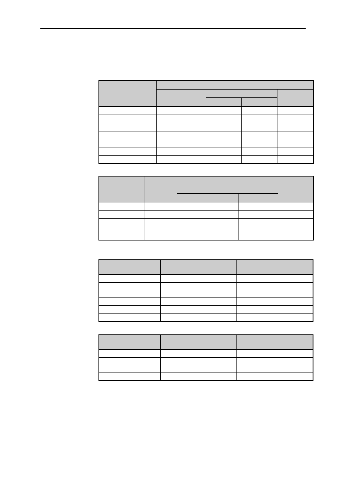
The smallest f ully func tional PLC unit of the TC600 seri es is formed by
the basic module (BM). It is produced in six designs which dif fer in the num ber and type of inputs and outputs.
Order numbers f or
BM PLC of the T C600
series
Type Order Number
1)
Binary
inputs
Analog
inputs
Note
Transist.
outputs
Relay
outputs
TC601 TXN 061 51 12 - 8 TC602 TXN 061 52 20 - 16 TC603 TXN 061 53._ _ 12 - 4 4
TC604 TXN 061 54._ _ 16 - - 10
TC605 TXN 061 55._ _ 12 4 - 8
TC606 TXN 061 56._ _ 16 4 4 10
TC607 TXN 061 57._ _ 20 - 20 -
1)
In types TC603 t o TC607, the after-num ber ( two digits af ter the dot)
determine the special B M function:
.00 common function of binary input s (after-number need not be given)
.01 4 interruption binar y inputs
.03 measuring by increm ental position scanner
.05 counter of type 3 (uni directi onal 16 bit counter with pre-selection)
.06 period and phase shift measurement
Optional part of al l BM t ypes are int erf ac es of t wo serial c om m unic ati ons
channels (CH1, CH2) f itted i n the standard design, addi tional data m emory
(DataBox) , and a third serial com munication c hannel (CH3) or analog outputs.
Order numbers of
optional BM
piggybacks
Type Order number Note
MR-02 5XK 068 91 Interface RS-232 without galv anic separation
from internal control ci rcui t s
MR-04 5XK 068 93 Interface RS-485 without galv anic separation
from internal control ci rcui t s
MR-09 TXK 085 03 Interface RS-485 with galv anic separation from
internal control circuits
MR-17 TXK 085 11 Interface RS-422 without galvanic separation
from internal control ci rcui t s
IM-70 TXK 080 10.00 DataB ox, additional dat a memory 128 k B
IM-70 TXK 080 10.02 DataB ox, additional dat a memory 512 k B
MR-14 TXK 085 08.02 CH3 with interfac e RS - 485 without galvanic
separation f r om inter nal control c ircuit s
MR-15 TXK 085 09.02 CH3 with RS-232 without galvanic separat ion
from internal control ci rcui t s
OT-13 TXK 082 60 4 analog outputs without galvanic separation
from internal control ci rcui t s
OT-14 TXK 082 61 8 analog outputs without galvanic separation
from internal control ci rcui t s
1)
DataBox is added in the production plant exclusively
2)
Only 1 pi ggy bac k M R- xx or 1 piggyback OT - xx may be fitted
2)
2)
2)
1)
1)
2)
Number of binary and analog inputs and binar y output s of the BM can be
extended by connecting one extension module (EM), two half extension modules (EM/2) or by combination of EM, EM/2.
TXV 138 08.02 6

Technical equipment of TC600 PLC
Order numbers of E M
and EM/2, PLC of the
TC600 series
Type Order number Note
Binary
inputs
Analog
inputs
Transist.
outputs
Relay
outputs
TC621 TXN 061 71 12 - 8 TC622 TXN 061 72 20 - 16 TC623 TXN 061 73 12 - 4 4
TC624 TXN 061 74 16 - - 10
TC625 TXN 061 75 12 4 - 8
TC626 TXN 061 76 16 4 4 10
TC631 TXN 061 81 8 - 8 TC632 TXN 061 82 8 - - 8
TC633 TXN 061 83 16 - - TC634 TXN 061 84 - 8 - -
2.6 Design
Modules of PLC's of the TC600 series are designed as devices to be
E N 50022
(idt EN 50022:1977). Metal jacket of the modules and m echanical arrangement guarant ees hi gher r esi stanc e against interferences.
BM electroni c circ uits are real ized on t wo printed wiri ng boards; the central uni t and input and output unit.
EM's are fitted with t he input and output unit only.
7 TXV 138 08.02
Tecomat TC600
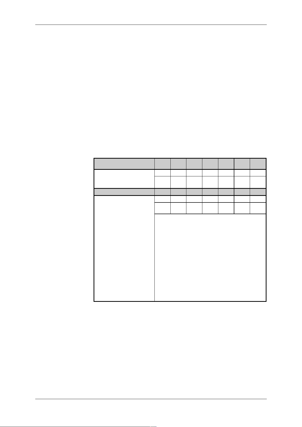
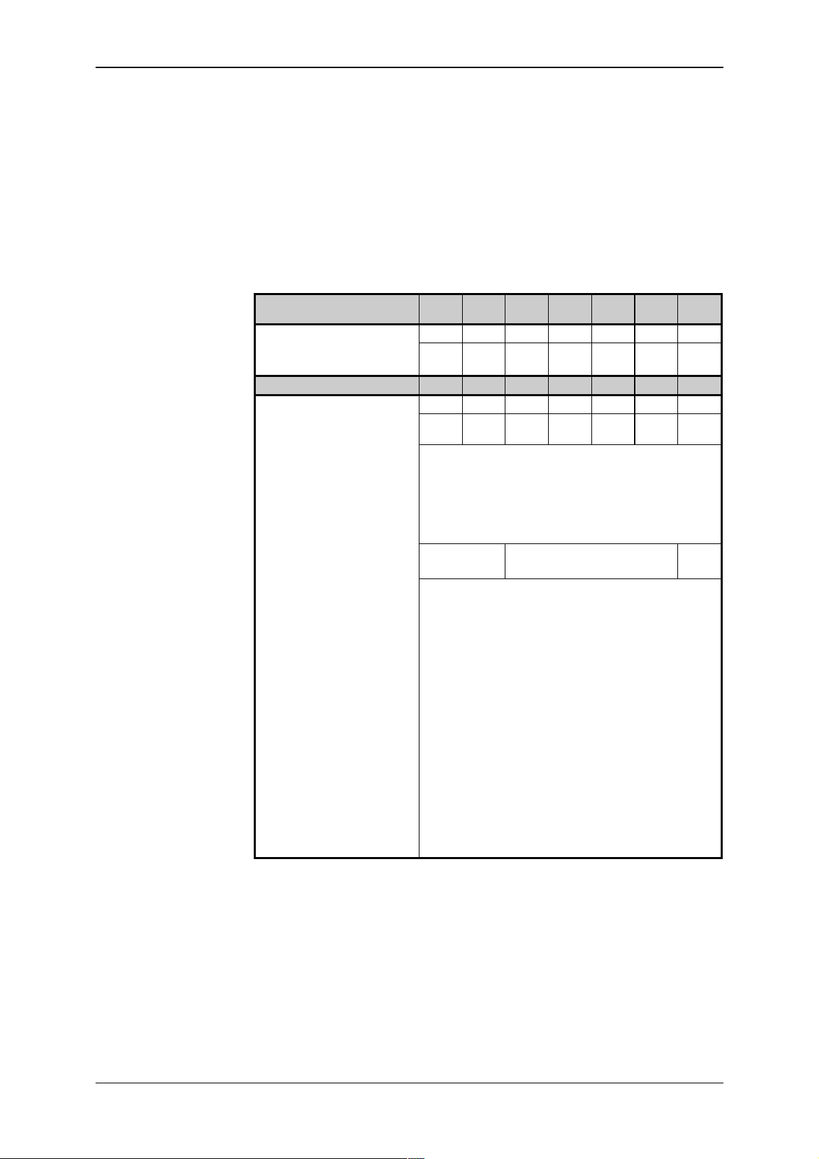
Number of inputs and
outputs of PLC TC600
series
3. Parameters Overview
3.1 Basic Properties
TC601
TC621
Binary inputs
Total number of inputs 12 20 12 16 12 16 20
Arrangement
(no. of groups x no. o f inputs)
Binary transistor out put s
Total number of out puts 8 16 4 - - 4 20
Arrangement
(no. of groups x no. o f outputs)
Binary relay outputs
Total number of out puts - - 4 10 8 10 Arrangement
(no. of groups x no. o f outputs)
Analog inputs
Total number of inputs - - - - 4 4 Arrangement
(no. of groups x no. o f inputs)
Analog outputs
Total number of out puts
Arrangement
(no. of group x no. of outputs)
TC602
TC622
1x8,
1x4
2x8,
1x4
TC603
TC623
1x8,
1x4
TC604
TC624
TC605
TC625
2x8 1x8,
1x4
TC606
TC626
TC607
2x8 2x8,
1x8 2x8 1x4 1x4 2x8,
1x4 2x4,
2x1
2x4 2x4,
2x1
1x4 1x4
TC601 to TC606
4 or 8 - optional
1x4 or 1x8
1x4
1x4
TC631 TC632 TC633 TC634
Binary inputs
Total number of inputs 8 8 16 Arrangement
(no. of groups x no. o f inputs)
2x4 2x4 4x4
Binary transistor out put s
Total number of out puts 8 - - Arrangement
(no. of groups x no. o f outputs)
1x8
Binary relay outputs
Total number of out puts - 8 - Arrangement
(no. of groups x no. o f outputs)
2x4
Analog inputs
Total number of inputs - - - 8
TXV 138 08.02 8

Technical equipment of TC600 PLC
3.2 Operational Conditions
Class of environment effect 33 2000-3
(mod IEC 364- 3:1993)
Range of operational temperatures
Aver age temperatur e dur ing 24
hours
Allowed transportation temperature
Relative ai r humidi ty 50 % to 95 % without condensation
Degree of pol lution
(idt EN 61131-2:1992, IEC 1131-2: 1992)
Ov er vol tage category of installation
33 0420
(eqv IEC 664:1980, IE C 664A :1981)
Immunity against disturbances
(idt EN 61131-2:1992, IEC 1131-2: 1992)
Emitted disturbance levels for gr oup 1, class A
Vibrations Fc 10 Hz to 150 Hz, 0.15 mm, 10 cycles
!
IEC 68-2-6:1995+Corr.1995)
Operating posi tion vertical
Type of oper ation permanent
0 °C to +55 °C
max. +50 °C
-25 °C to +70 ° C
(tab. 16)
(mod CISP R 11:1997)
(idt EN 60068-2- 6:1995,
3.3 Basic Parameters
BM EM EM/2
Type of appliance to be built-in
Class of el. object
(mod IEC 536- 1:1976, IEC 536-2: 1992)
Coverage IP-10B
Supply voltage
(SELV)
Power input max. 20 VA
Mass about 0.8 kg about 0.4 kg about 0.2 kg
Size (h x w x d)
1)
Power input of B M extended by one EM and one E M /2
2)
See fi gs. 9.1, 9.2, 9. 3
2)
24 V~ ±20 %,
50-60 Hz ±5 %
or 24 V- ±20 %
or 13 W
1)
141x182x69 141x157x44 141x89x44
9 TXV 138 08.02

Tecomat TC600
4. Central Unit
4.1 Basic Parts and Parameters
Central unit ensures the majority of PLC control functions. Due to its
properties, i t i s ranked am ong T ecom at CP U D series. It contai ns especi al ly
the supply voltage converter, microcontroller, memories RAM and
EEPROM, RTC circuit , lithium battery to supply v oltage to the RAM mem ory and RTC cir cui t i n the c ase that t he PLC power supply i s t urned of f , t wo
serial communication channels and optional additional data memory and
analog output circuit s or a t hird serial c ommunication channel.
CPU Basic
parameters
Central uni t series D
Real time circ uit (RTC) fitted i n standar d desi gn
User program source m emory fitted in standard design
Memory type EEPROM (FLASH)
Memory size 32 kB
User program and data memory fitted in standard design
Memory type RAM
Memory size 32 kB
Additi onal data memory, Dat aB ox optional
Memory type RAM
Memory siz e 128 kB or 512 kB
Backup of the RAM memory and RTC min. 20 000 h
Cycle peri od per 1k of logic instruct ions 13 ms
Total number of user registers 8 192
Number of remanent r egisters optional 0 to 512
Total number of timer s and count er s 4 096
Range of timers 65 536 x 10 ms to 10 s,
possibility of cascading
Range of counter s 65 536, possibility of cascading
Instructi on set extended
Instructi on length 1 to 6 bytes
Number of serial communi c ation chan-
nels
Transmission speed of CH1, CH2, CH3 0.3 t o 230.4 kBd
Number of analog outputs optionally 0, 4 or 8
2 + 1, optional
1)
1)
Maxim um tr ansmission speed is lim ited by the max im um al lowed transmission speed of the set communication channel m ode.
4.2 User Accessible Memories
User program
memory
User program source
memory
TXV 138 08.02 10
Memory of the user program is f orm ed by a part of the RAM m em ory of
CPU assigned for the user progr am, data and tabl es. When PLC is turned
off, the m emory is supplied by the built-in lithi um battery .
Source memory of the user program is formed by a part of the EEPROM
memory of CPU assigned for saving of a copy of the user program. The
memory power-independent, that is, contents of the memory remain retained even after the power supply of the PLC is turned off or when the
battery i s di scharged. Use of the source memory is contr olled by the user by
setting a parameter in t he P LC S E T mode (see Article 4.5) .
When the source mem or y is allowed, after exiting the SET mode, turning
on of the PLC power supply or restart, c ontents of the user program source
memor y is mov ed to the user program mem ory with which CP U works. The
functi on is used especially for backup of the user program. The m emory is
programmed from within t he devel opment environment direc tly in the PLC.

Technical equipment of TC600 PLC
Memory of CPU
parameters
Scratchpad memory
The DataBox
Support of w or k ing
with the Dat aB ox
Backup of the RAM
memory and RTC
circuit power s upply
Detection of state of
the backup batter y
Memory of CPU param eters is power-independent m emor y designed for
storage of param eters that can be set in the PLC SE T mode. Contents of
the mem ory rem ain ret ained ev en when the PLC power supply i s turned off
or if the battery is discharged.
The scratchpad m emory is a part of the CPU RAM memory accessible to
the user in the f orm of i nput i mages (regi sters X), outputs i mages ( registers
Y), system (S) and user registers (R). Preserving of the scratchpad cont ents
after t urni ng of f of the PLC power supply and restart s i s program - contr oll ed.
The behav iour is described in detail in Chapter 10.
The DataBox is an optional compl ement of the CPU, fi tted by the producer on the basis of an or der. I t ex t ends t he user accessibl e RAM m em ory
by 128kB or the data memory by 512kB. When the P LC is turned off, the
memor y is supplied fr om a bui lt-i n li thium batt ery. It is designed f or working
with greater amounts of data, f or exampl e for arc hiv ing of dat a on the controll ed process for a longer t ime period et c. The data can be writt en to the
memory or read, respectively, either by using the PLC user program or
through the serial line.
For support of the DataBox program attendance, there are thr ee user instructions available. The READDBX instruction is intended for reading of
data from DataBox into R regi sters, the WRI TEDBX instructi on is intended
for writing of data from R registers to the DataBox, and the SIZEDBX instruction serv es for identi fication of the DataBox size. Detailed descripti on
of function of instructions, their definitions, structures of the parameters
zone for i nstructions READDBX and WRI TEDBX and way of c alling of instructions in the user program are given on t he distribution disket te xPRO
which forms a part of the PLC delivery.
For serial communication with the DataBox, either CH1 can be used
which always operates in the PC m ode or c hannels CH2, CH3 set i n the PC
mode. To support serial communication with the DataBox, the
COMPLC.EXE program is av ai labl e which all ows for reading data f rom DataBox i nto a fi le or write dat a from a fil e to DataBox , respectiv ely, and test
size of memory accessible in the form of the DataBox. W orking with the
DataBox i s possible starti ng from the CO MPLC.EXE program version 1. 6.
The program, which is found on the x PRO distr ibuti on diskett e, must be r un
under the MS DOS oper ating system.
When the PLC power is turned of f, the RA M memory and RTC circuit are
supplied from a bui l t-i n l i thi um batt ery. Param et ers of the used batt ery al l ow
for backup wit h the power supply turned of f f or the m ini mum t im e of 20000
hours. In common operating conditions (operating temperature of 20 °C,
unidirectional operation at least) and typical power take-off of the backing
circui ts, the backup time is l imi ted by battery life (5 years at the minimum).
Voltage of the backup battery i s evaluated by the diagnostic system. In
the case the vol tage drops under 2.5 V, bit .0 of the S35 system regi ster is
set to the state log. 1. PLC cont inues with it s activ i ty unti l t he v oltage drops
under the minimum supply voltage of the RTC circuit. Evaluation of the
RTC circuit failure leads to bringing the PLC in the HALT mode and announcing the error message 80 0C 00 00.
11 TXV 138 08.02

Tecomat TC600
4.3 Analog Outputs
Analog outputs are used for control of v olt age-control acti on elem ents of
the control led obj ect . T hey are ar ranged i n a group wit h a com m on ter m inal
of the analog ground. Analog outputs are galvanically connected with the
CPU control circuits. Physically, the analog outputs are realised on small
plug-in units, the so called piggybacks, fitted on the CPU if ordered. Number
of output s depends on the ty pe of the chosen piggy bac k ( see Article 2.5).
Parameters of analog
outputs
OT-13 OT-14
Number of output channel s 4 8
Arrangement of outputs 1x4 1x8
Common gr oup c onduc tor minus
Galvanic separation from inter nal
control circuits
Type of output voltage
Voltage range/ r esol ution (1 LSB 1))
Error of output voltage
Binary output representation 8 bits
Output curr ent max. 10 mA
Setting time of the output
Output l oad r esi stanc e
Resistance against short-circuit min. 5 s
1)
LSB (Least Signifi c ant Bit) - lowest bit of the binar y val ue
1 LSB =
0 to 9.96 V/ 39 mV
no
typ.
1 LSB
max.
4 LSB
max. 30 s
>1 k
TXV 138 08.02 12

To program the PLC,
communication
channel CH1 is used
Interface RS-232 of
CH1 is activated af ter
connection of the
interconnecting cable
TXK 646 51.06
Technical equipment of TC600 PLC
4.4 Serial Communication Channels
Standard design of all PLC's of the TC600 series is equipped with two
comm unication channels. Thi rd communi cation channel is added per order
(see Article 2.5).
4.4.1 Serial Communication Channel 1 (CH1)
CH1 is designed for c onnecti on of t he PLC t o a superior system . The superior system most of ten repr esents a computer of the P C class perfor mi ng
the funct i on of a program m i ng devic e, visual isati on stat ion or contr ol devi ce
of the PLC network. It contains a complete set of the EPSNET network
servi c es. Detailed description of the services is given in the handbook
Communication of T ec om at P r ogr am m able Logic Controllers,
TXV 001 06.02.
CH1 is equipped with fix ed fit ted interface RS-232 without galvanic separation f rom internal circuits. Besides this, in all types of BM, CH1 can be
complem ented with a piggyback with int erface RS- 485 or RS-422. Opt ional
interf ace is impl ici tl y assigned to CH1. Interface RS -232 is assigned to CH1
automati cally by connecting the cable TXK 646 51.06. Together with connecting interface RS-232, the optional interface (if fitted) is disconnected
from CH1. For selection of the inter face ty pe, especiall y functi on of the superior dev ice is decisiv e, type of int erfac e of i ts serial comm unicat ion channel, connect ion distance, transmission speed and level of disturbanc es.
Serial
Interface RS-232 is
used for tw o- point
connection
Parameters of the
RS-232 interface
4.4.1.1 Interface RS-232
Interface RS-232 ensures conversion of output signals of TTL level to
level defined by the specification V.28 (EIA RS-232), and of input signals
according to V .28 to the TTL l evel. I t allows for connec tion of two end devi ces in the duplex mode. I t is suitabl e for c onnection r ealised i n short di stance in an environment with low level of electrom agnetic distur banc es.
For the com municat ion, PLC's of the TC600 series use only bi nding ci rcuits of signal s TxD (Transmit Data), RxD (Receiv e Data), CTS (Cl ear To
Send), and RTS (Request To Send) of the standard RS-232 int er face.
Transmission speed max. 230.4 kBd
Cable length m ax. 15 m
Voltage of outputs TxD, RTS for level 1
Voltage of outputs TxD, RTS for level 0
typ. -8 V against GND (R
typ. +8 V against GND (R
2)
1)
=5 k
l
=5 k
l
Voltage of inputs Rx D, CTS f or lev el 1 min. -3 V against GND
max. -25 V against GND
Voltage of inputs Rx D, CTS f or lev el 0 min. +3 V against GND
max. +25 V against GND
Impedance of inputs RxD, CTS
1)
The maximum transmission speed is limited by the maximum allowed
transmission speed of the set mode of the communic ation channel.
2)
The maximum cable length may only be used provi ded that the maxi-
5 k
mum transmission speed is reduced.
13 TXV 138 08.02

Tecomat TC600
Interface RS-485 is
used for multi-point
connection
4.4.1.2 Interface RS-485
Interf ace RS-485 ensures conversion of output signal s of t he TTL l evel
to lev el def i ned by t he specificat i on V.11 (X.27, EIA RS -485), and i nput signals according t o V.11 to the TTL lev el. Param eters of sym metric bi nding
circui ts of the RS-485 int erface all ow for mul ti-point connection of end devi ces in the half -duplex mode. It is suitable f or connection reali sed in medium di stance i n an environm ent with hi gher l evel of elect rom agnet ic distur bances.
For the communic ation, PLC's of the TC600 series use binding circuit s of
signals TxD (Transmi t Data), RxD (Recei v e Data). Signal RTS (Request To
Send) is used internally for control of the tr ansmitter ac tivation.
Parameters of the
RS-485 interface
Transmission speed max. 230.4 kBd
Cable length max. 1200 m
Sensitivity of differential inputs
±200 mV
1)
2)
RxD+, RxDInput resistance of differential inputs
min. 12 k
RxD+, RxDVoltage of different ial inputs
RxD+, RxD- f or lev el 1
Voltage of different ial inputs
RxD+, RxD- f or lev el 0
Voltage of different ial output s
TxD+, TxD- for level 1
Voltage of different ial output s
TxD+, TxD- for level 0
Difference of the output vol tage
min. 0.2 V
max. 12 V
min. -0.2 V
max. -7 V
min. 1.5 V (R
max. 5 V Io=0)
min. -1.5 V (R
max. -5 V Io=0)
max. ±0.2 V
=75
l
=75
l
value for levels 0 and 1
Output curr ent max. ±250 mA
1)
The maximum transmission speed is limited by the maximum allowed
transmission speed of the set mode of the communic ation channel.
2)
The maximum cable length may only be used provi ded that the maxi-
mum transmission speed is reduced.
TXV 138 08.02 14

Interface RS-422 is
used for tw o- point
connection
Technical equipment of TC600 PLC
4.4.1.3 Interface RS-422
Interface RS-422 of PLC's of the TC600 series ensures conv ersion of
output signals of the TTL level to lev el defined by the specification V.11
(X.27, EIA RS-422), and input signals according to V.11 to the TTL lev el.
Parameter s of symmetr ic binding ci rcuits of t he RS-422 int erface al low for
two-point connection of end dev ices in the duplex mode. It is suitable f or
connection reali sed in m edium distance i n an env ironm ent with hi gher lev el
of elec tromagnetic disturbances.
For the com municat ion, PLC's of the TC600 series use only bi nding ci rcuits of signals TxD ( Transm i t Dat a) and Rx D (Recei ve Data) of the RS-422
interf ace.
Parameters of the
RS-422 interface
Transmission speed max. 230.4 kBd
Cable length max. 1200 m
Sensitivity of t he differenti al input
±200 mV
1)
2)
RxD+, RxDInput resistance of the diff er ential
min. 12 k
input Rx D+, RxDVoltage of the differ ential input
RxD+, RxD- f or lev el 1
Voltage of the differ ential input
RxD+, RxD- f or lev el 0
Voltage of the differ ential out put
TxD+, TxD- for level 1
Voltage of the differ ential out put
TxD+, TxD- for level 0
Difference of the output vol tage
min. 0.2 V
max. 12 V
min. -0.2 V
max. -7 V
max. 5 V Io=0)
2.3 V (R
=100
l
max. -5 V Io=0)
-2.3 V (R
=100
l
max. ±0.2 V
value for levels 0 and 1
Output curr ent max. ±60 mA
1)
The maximum transmission speed is limited by the maximum allowed
transmission speed of the set mode of the communic ation channel.
2)
The maximum cable length may only be used provi ded that the maxi-
mum transmission speed is reduced.
15 TXV 138 08.02

Tecomat TC600
CH2 is designed for
general use
CH3 is designed for
general use
4.4.2 Serial Communication Channel 2 (CH2)
CH2 serves especial ly f or connect ion of int elli gent peri pheries with a serial input or output of data to the PLC, and for mutual interconnection of
PLC's. It can operate in sev er al modes:
Mode PC - c onnec tion of a superior system, usually a PC
Mode PLC - interconnection of PLC's or regulators for mutual tr ansfer of
data
Mode MAS - data collection from subordinate PLC's or regulators in the
EPSNET network
Mode uni - general user channel for universal use
Setting of the required mode is giv en in Arti cle 4.5, detai led descripti on
of the m odes is given in the handbook
Serial Communication of Tecomat
Programmable Logic Contr oller s , TXV 001 06.02.
CH2 interf ace is optional (see Article 2.5). Parameters of the interf ace
are given under item 4.4.1.
4.4.3 Serial Communication Channel 3 (CH3)
CH3 is an optional par t of the P LC. It can be complem ented only in types
without analog out puts. It serv es especially f or c onnection of i ntelli gent peripheries with a serial input or output of data or connecti on of an external
control board, mutual interconnect ion of P LC's or connection of a PLC to a
superior system. It can operate in several modes:
Mode PC - c onnec tion of a superior system, usually a PC
Mode PLC - interconnection of PLC's or regulators for mutual data
transfer
Mode MAS - data collection from subordinate PLC's or regulators in the
EPSNET network
Mode uni - general user channel for universal use
Setting of the required mode is giv en in Arti cle 4.5, detai led descripti on
of the m odes is given in the handbook
Serial Communication of Tecomat
Programmable Logic Contr oller s TXV 001 06.02.
CH3 interfac e is dependent on the type of the c omm unicat ion piggy back
(see Article 2.5). Interface par ameters are given under item 4. 4.1.
TXV 138 08.02 16
Mode SET
Displaying of
parameters
Entrance in the SE T
mode
Termination of the
SET mode
Adjustable
parameters
Technical equipment of TC600 PLC
4.5 Setting of CPU Parameters
CPU parameters are set in the setting mode (mode SET). To set and
display paramet ers, the PLC front boar d is equipped with buttons SET and
MODE and a one-plac e seven-segment LE D display.
In the SET mode, all data are displayed in the rotational way, that is,
number 123 is displayed in such a way that digits 1, 2, 3 are l ighted gradually on the display, then there is a delay, and the whole sequence is repeated. Ev ery character i s displayed for about 0. 5 s and is separated f rom
the foll owing charac ter by a delay which ensures recognit i on of two ident i cal
characters display ed one aft er another (f or ex ampl e, di splaying of the num ber 111).
Switching t o the SET mode can be perf ormed by pressing butt ons SET
and MODE sim ultaneously whil e the PLC power supply is on. Buttons S ET
and MODE are held pr essed unti l the triple dash appears on the display. In
general it holds that by t he SET butt on we change setting of the param eter,
and by the MODE but ton we mov e t hrough i ndiv i dual paramet ers. Pressing
of the but ton is indic ated by lighting of the decim al point on t he display.
The SET mode m ay be term inated any ti me by sim ultaneously pr essing
the buttons SET and MODE. W e again hold the buttons SET and MODE
pressed until the t r iple dash appears on the display. Stat e of param et ers is
saved upon term ination of the mode in the power-independent m emory of
parameters, and the PLC switches to the HA LT m ode or som e of err or m essages may possibly be signalled.
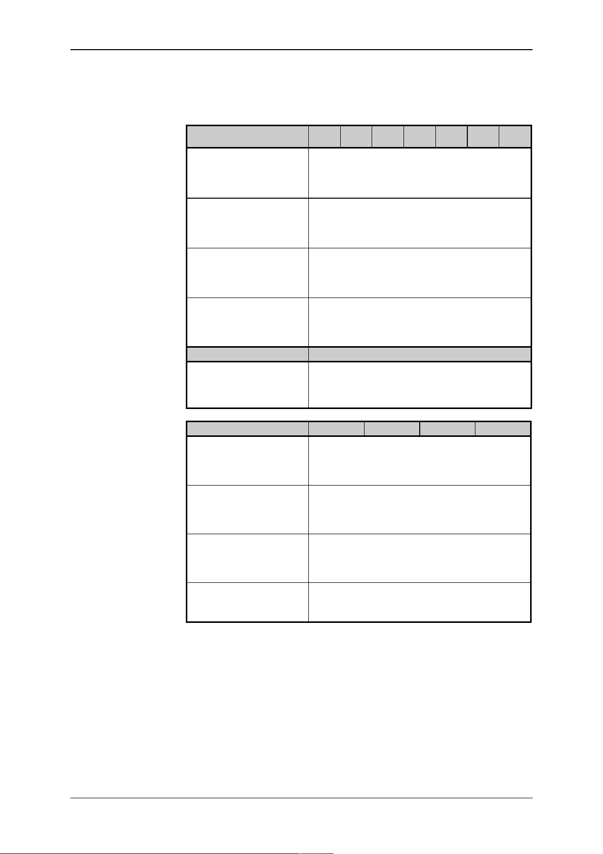
Tab. 4.1 Adjustable CPU parameters
(ordered fr om the left to the right and in the rows)
Setting of t he s er ial
channel mode
Object to
Adjustable parameters
be set
channel CH1 - address speed delay of re-
ply
CTS detec-
tion
off - - - -
channels
CH2 and CH3
Program source
mode PC
reg. PLC
1)
reg. uni
mode
MAS
address speed delay of re-
ply
address speed - -
- speed transport
delay
-- - -
off
CTS detec-
tion
CTS detec-
tion
2)
memory
on
1)
Only BM's fitted with the communication piggyback contain channel
CH3.
2)
CTS detection in the MAS mode cannot be set for CH3.
4.5.1 Setting of Parameters of Serial Communication Channels CH1,
CH2, CH3
Channel CH1 has fixed-set mode PC which c annot be changed. In this
channel, the par ameter serial channel mode is not set.
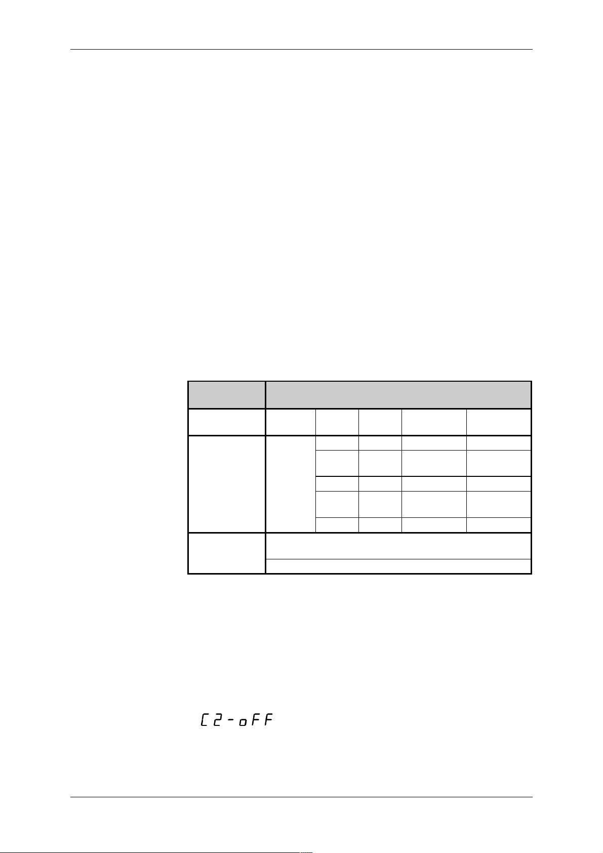
In setting the parameter serial channel mode for c hannels CH2, CH3, a
message of the foll owing type is shown on the display
with the f ollowing m eaning:
C - setting of t he serial channel mode
2 - number of t he c hannel being set
off- the mode being set
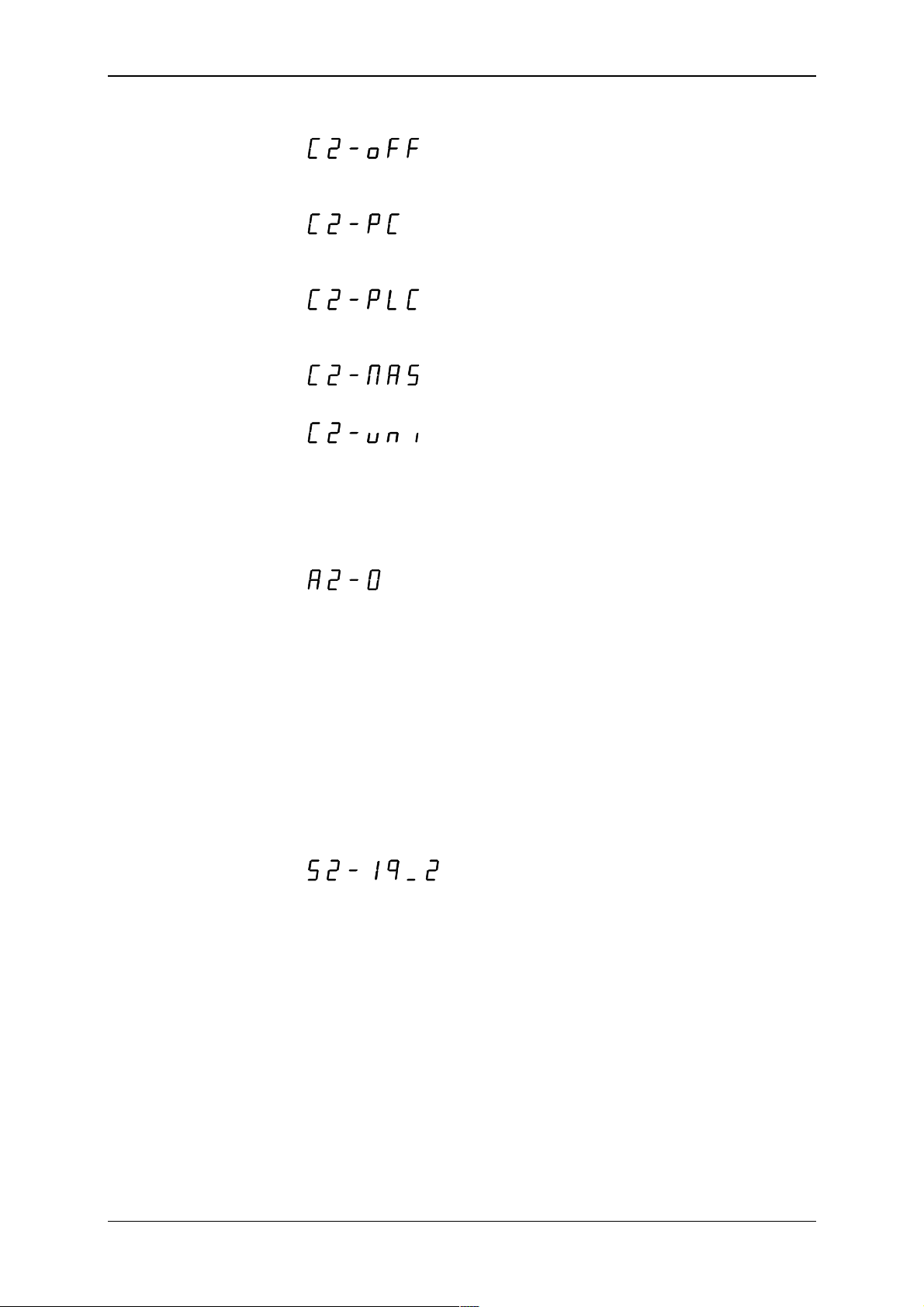
Serial c hannels may operate in the f ollowing m odes:
17 TXV 138 08.02
Tecomat TC600
off - channel is of f (no other c hannel paramet er is set)
PC - connection of a superior system (a PC or an active operation
board)
PLC - interconnect ion wit h other PLC's or regul ators i n t he EPSNET m ul-
tim aster network with fast dat a exchange
MAS - data collection from subordinate PLC's or regulators in the
EPSNET network
uni - general user channel for univ er sal use
By the SET but ton we move t hrough indiv idual modes. B y pressing the
MODE button we save the set mode and move to setting of another parameter
Setting of t he s er ial
channel address
Setting of t he s er ial
channel communication speed
When sett ing the param eter serial ch annel add ress, a message of the
following type is shown on the display
with the f ollowing m eaning:
A - setting of t he serial channel addr ess
2 - number of t he c hannel being set
0 - the set addr ess
Address may take a value from 0 to 99. By shortly pressing the SET
button, we increase i ts val ue by 1, by pressing and holdi ng the SET button
(for about 1s) we incr ease i ts val ue by 10. By pressing the MODE button, we
save the set value and move to setting of another parameter.
Address is set only f or modes PC and PLC. In the uni mode, setting of
the address is a part of the init ialisation table in the user program.
When setting the parameter serial channel communication speed, a
message of the foll owing type is shown on the display
with the f ollowing m eaning:
S - setting of the serial channel c ommunication speed
2 - number of the channel being set
19_2 - set speed in kb/s (the underscore is a substitute for the decimal
point)
The speed may take v alues defined in adv ance according to t able 4.2.
Speed not av ailabl e in the giv en m ode of the gi ven channel, i s not of fered
when browsing by the SET button. By pressing the MO DE button, we save
the set v alue and move to setting of anot her par ameter.
The speed is set only f or modes PC, PLC and MAS. In the uni m ode,
speed setting is a part of the initialisation t able in the user program.
TXV 138 08.02 18
Technical equipment of TC600 PLC
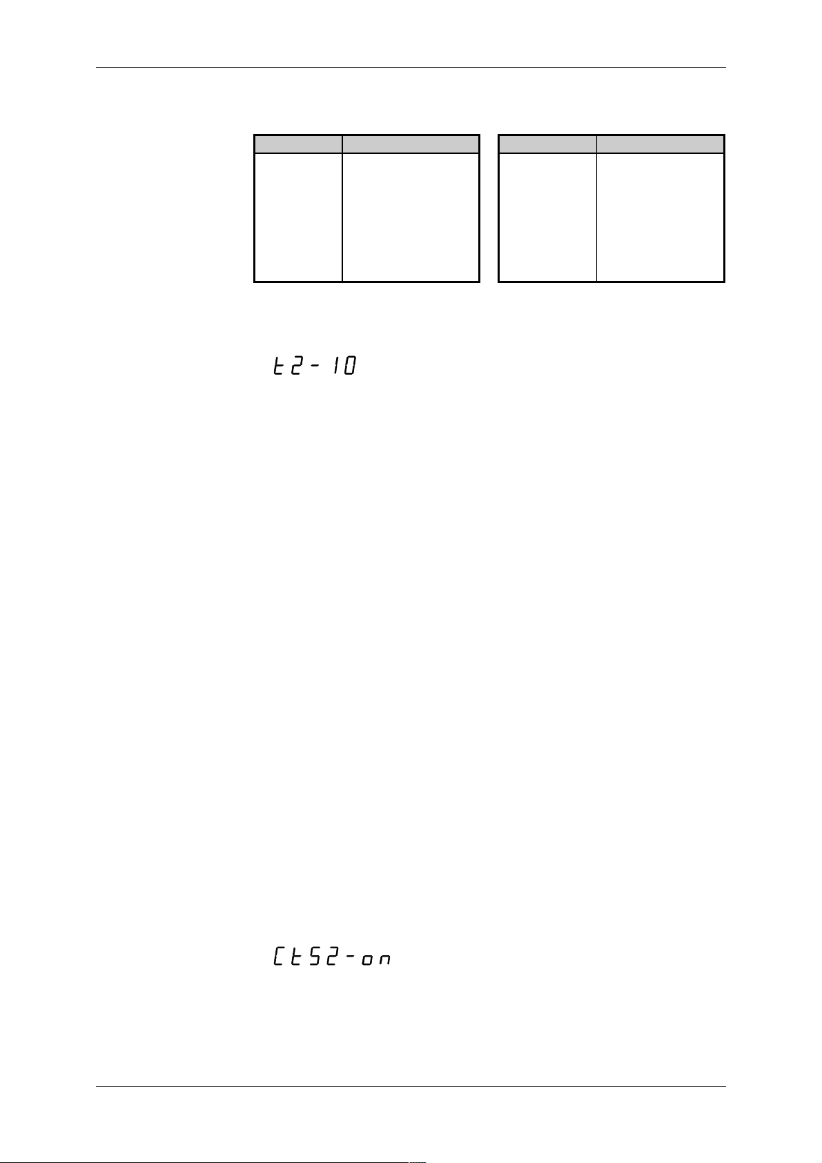
Tab. 4.2 List of available transmission speeds of CH1, CH2 and CH3 in
various modes
Speed Channel mode Speed Channel mode
0.3 kb/s PC,MAS 28.8 kb/s PC,PLC,MAS
0.6 kb/s PC,MAS 38.4 kb/s PC,PLC,MAS
1.2 kb/s PC,MAS 57.6 kb/s PC,PLC,MAS
2.4 kb/s PC,MAS 76.8 kb/s PLC
4.8 kb/s PC,MAS 115. 2 k b/s PLC
9.6 kb/s PC,PLC,MAS 172.8 kb/s PLC
14.4 kb/s PC,PLC, M A S 230.4 kb/s PLC
19.2 kb/s PC,PLC, M A S
Setting of t he r eply
delay and transport
delay
Reply delay
Transport delay
When sett ing the param eter reply delay (in the PC m ode) or transport
delay (in the MAS mode), a message of the f ollowing type i s shown on the
display
with the f ollowing m eaning:
t - setti ng of the reply delay
2 - number of t he c hannel being set
10 - set delay/transport delay in ms
By shortly pressing the SET button, we increase the value of the delay/tr ansport delay by 1, by pr essing and holding the SET button (f or about
1s) we increase its v alue by 10. B y pressing the M ODE button we save the
set value and move to setting of another par ameter.
Optional reply delay serv es for solut ion of si tuations when the superior
system sending the message, cannot switch in time from transmission mode
to receiv ing m ode, and thus it cannot receiv e t he PLC's reply. By ex tending
the reply delay t he superior system gai ns time f or preparati on necessary to
start receivi ng of a reply .
The delay ti m e i s set in m s and m ay take values f rom 0 to 99 m s. Val ue
0 means that the mini mum reply delay shall correspond with the time necessary to transmit 1 byte, thus it depends on the set speed. Val ues 1 to 99
give the delay in milliseconds and are not dependent on the comm unicati on
speed.
The reply delay is set only for mode PC.
Optional transport delay serv es for soluti on of si tuat ions when the PLC i n
the role of the superior system is waiting for reply from a subordinate PLC
for l onger than 0.5 s for t he r eason of delay on the t r ansmission l ine, caused
by modem s etc .
Transport delay is set in multipl es of 100 m s and may take values from 0
to 6 s. Value 0 means that the superior PLC waits for the reply for the
maxi mum of 0.5 s (ti me of cycle of the subordinate PLC may not exceed
this value). Values 1 to 60 give the transport delay of 0.1 to 6 s which is
added to the v alue 0. 5 s. Values 61 to 99 set the m ax im um transport delay
of 6 s.
The transport del ay is set only f or mode MAS.
Setting of t he CTS
signal detection
When setting the param eter CTS signal detection, a message of the
following type is shown on the display
with the f ollowing m eaning:
CTS - setting of the CTS signal detection
2 - num ber of the channel being set
on - det ec tion on
19 TXV 138 08.02

Tecomat TC600
Detection of the CTS si gnal may be either of f or on. By pressing the SET
button we change the setting, by pressing the MODE butt on we save t he set
value and move to setting of another par ameter.
When detect ion of the CTS signal is on, bef ore t ransmission of the repl y
the PLC tests state of the CTS signal af ter setti ng the RT S signal . The repl y
is transmitt ed only if the CT S signal has the sam e v alue as the RTS signal.
This mode i s suitable for com municat ion vi a modems. The set reply delay
holds in this mode too, it is thus ensured that PLC shall not reply before t he
delay elapses even if the CTS signal is already set.
When CT S signal det ecti on is of f, PLC control s the RTS signal but does
not take into considerati on state of the CTS signal.
Detection of the CTS si gnal can be set for the PC mode of all channel s
and for the MAS mode f or channel CH2. For channels CH2 and CH3 in the
uni mode, detec tion of the CTS signal c an be set using the ini tiali sation table in the user progr am.
Default sett ing of
parameters
Parameter s of CH1 are implicitly set by the producer to the following
values: mode - PC, addr ess - 0, speed - 19.2 k b/s, delay - 0, CTS detection
- off
CH2 and CH3 are implici tly off.
4.5.2 Management of the user p rogram source memo ry
When setti ng parameters of the source memory, a message of the fol lowing type i s shown on the display
with the f ollowing m eaning:
EP - setting of the user program source memory
off- m emory off (default val ue)
The source mem ory m ay be eit her of f or on. By pr essing t he S ET but ton
we change the setting, by pressing the MODE but ton we save t he set v alue
and move to setti ng of another parameter.
When t he param et er i s set to the of f v al ue, after t he PLC switches to t he
RUN mode, program stored in the user program memory i s run. When t he
parameter is set to the on value, after the setting mode is ended and in
every subsequent turning on of the PLC power supply, program from the
source memory is first moved to the user program m emory, and this program is then run in the RUN mode. The function serves especially for
backing of power-dependant memory of the user program.
TXV 138 08.02 20
Technical equipment of TC600 PLC
5. Input and Output Unit
5.1 Basic Functions
The majori ty of input and output circui ts of the PLC is real ized on t he input and output unit. Indiv idual types of the series diff er in the type of the
used input and output unit or i n m odificat i on of the uni t f i tt ing wit h ci rcui t s of
binary and analog inputs and binary t r ansi stor and r elay outputs.
5.1.1 Binary Inputs
Binary i nputs serve for c onnection of t wo-state signals of the contr olled
object to t he PLC. To increase f unctional rel iability, every input is galv anically separated by an optical el ement f rom i nternal ci rcuits and is equi pped
with a fi l ter. If the i nput i s exc it ed (cl osed), t hi s is signall ed by l i ghti ng of t he
LED diode. Input s are organized in groups with one c ommon connec tor. A
group of signals may be connected in one or the other polarity .
Inputs DI1 to DI3 of modules TC603 to TC607 can be used for basic
functi on i denti cal wit h other i nput s or f or real i zati on of t he PLC speci al functions.
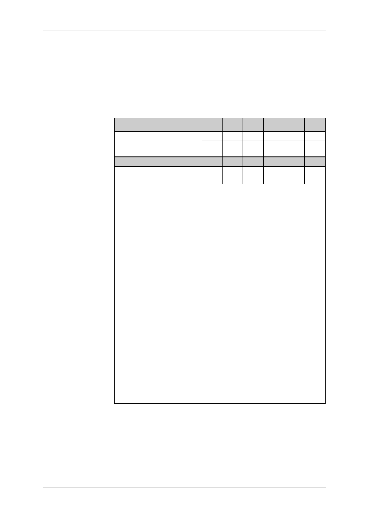
Parameters of binar y
inputs
TC601
TC621
Total number of inputs 12 20 12 16 12 16 20
Arrangement
(no. of groups x no. o f inputs)
TC631 TC632 TC633 TC634
Total number of inputs 8 8 16 Arrangement
(no. of groups x no. o f inputs)
Group common conductor plus or mi nus
Galvanic separation f r om
other electric circuits
Nominal vol tage 24 V-, 24 V~
Voltage for log. 0 max. 12 V-, 11 V~
Voltage for log. 1 min. 16 V- , 15 V~
Current for log. 1 typ. 10 mA
Delay from log. 0 t o log.1 typ. 4 ms
Delay from log. 1 t o log.0 typ. 4 ms
Pulse overload capacity of
the input
TC602
TC622
1x8,
1x4
2x4 2x4 4x4
TC603
TC623
2x8,
1x4
1x8,
1x4
(max. 14 V-, 13. 5 V~)
(min. 18.5 V-, 17.5 V~)
max. 30 V-, 30 V~
(pulse width 100 s, period 1 s)
TC604
TC624
2x8 1x8,
yes
max. 250 V
TC605
TC625
1x4
TC606
TC626
2x8 2x8
1)
1)
TC607
1x4
1)
Value val i d for inputs DI0 to DI3 of m odul es TC603 to T C607 and TC623
to TC626
21 TXV 138 08.02
Tecomat TC600
5.1.2 Binary Transistor Output s
Binary tr ansistor outputs serv e f or contr ol of two-state act ion and signal ling el ements, which require hi gh count and el. cl osing speed. To i ncrease
functional rel iability, every output is galvanically separated by an opti c al element fr om internal cir cui ts and is protect ed against short ci rcui t, overv ol t age
and rever si ng of polarity.
When connecting an external power supply of outputs, closing of individual outputs i s signalled by lighting of the LED di ode. By lighting, the common LED diode marked as BLK, signals blocking of outputs in the still
(open) state.
Outputs are organi z ed in groups with one common connector.
Parameters of
transistor outputs
TC601
TC621
TC602
TC622
TC603
TC623
TC604
TC624
TC605
TC625
TC606
TC626
TC607
Total number of out puts 8 16 4 - - 4 20
Arrangement
(no. of groups x no. o f outputs)
1x8 2x8 1x4 1x4 2x8
1x4
TC631 TC632 TC633 TC634
Total number of out puts 8 - - Arrangement
(no. of groups x no. o f outputs)
1x8
Group common conductor plus
Galvanic separation f r om
yes
other electric circuits
Operational volt age of out-
9.6 V- to 28.8 V-
puts
Current of outputs max. 1 A
Current of the comm on
conductor
Residual current in el.
max. 6 A max. 4 A 6 A
4 A
max. 300 A
opening
El. closing time
El. opening time
Protection against short
max. 400 s
max. 400 s
yes
circuit
Limi t at ion of the initi al peak
typ. 7.5 A
current
Disconnecting tim e of the
typ. 4 ms
initial peak current
Limitation of short circuit
typ. 4 A
current
Protection against overload yes
Current limitation typ. 4 A
Protection against revers-
yes
1)
ing of polari t y
Servicing of inducti ve load external
1)
The circuit is brought in non-activ e state, loads are closed, current will
flow through the circuit protect iv e diode.
TXV 138 08.02 22
Technical equipment of TC600 PLC
5.1.3 Binary Relay O utputs
Binary rel ay outputs serve for control of two-state action and signalling
element s of the cont roll ed object , suppli ed by alter nating v ol tage or v oltage
higher than the allowed range of closed volt age of transistor outputs. O utputs are realized by the closi ng v oltage-f ree cont act rel ay led out independently or in a group with one com mon connector.
Closing of every output is signalled by lighting of the LED diode. The
comm on LED diode mark ed as BLK, signals by li ghting bl ocking of outputs
in the still (open) state.
Parameters of r elay
outputs
TC601
TC621
TC602
TC622
TC603
TC623
TC604
TC624
TC605
TC625
TC606
TC626
Total number of outputs - - 4 10 8 10
Arrangement
(no. of groups x no. of outputs)
TC631 TC632 TC633 TC634
1x4 2x4,
2x1
2x4 2x4,
2x1
-8-2x4
Galvanic separation from
yes
other elect r ic circ uits
Contact parameters
Closed voltage
max. 250 V
Closed current max. 1 A
Closed alternat ing output m ax. 250 VA
Closed direct- c ur r ent output m ax. 24 W f or vol tage 24 V
max. 43 W for voltage 48 V
max. 57 W for voltage 250 V
Current through t he gr oup
max. 4 A
comm on c onduc tor
Closing and opening t ime typ. 5 ms
Oscillation time typ. 1 ms
6
Mechanical life min. 20 x 10
closings
Serv icing of inductiv e load external
Protection of the c ontact
external
against overload
Dielect r ic resistance of the
1 kV~
open contact
Dielect r ic resistance between
2.2 kV~
relay contac ts and non-live
PLC parts
Dielect r ic resistance between
3.75 kV~
relay contac ts and SELV circuits
Dielect r ic resistance between
contact groups
1)
3.75 kV~
1)
Includi ng c ontacts led out independently
23 TXV 138 08.02

Tecomat TC600
Format of input data
5.1.4 Analog Inputs of TC605, TC606, TC625, TC626 Modules
Analog inputs serve for connection of up to four analog signals of the
controll ed object to the PLC. They are i ntended especial ly f or processing of
analog signals with normalized current or v oltage level. Input circuits are
galvanically connected wit h internal P LC c ontrol ci r c uits.
Inputs are arranged in a gr oup with one common connector of t he analog
ground. Ev ery input can be set indi viduall y by a jumper f or the voltage or
current signal source. T he m easurement range i s set by a pr ogram . T ype of
input and the measurement range c an be selected for every i nput independently of other inputs.
Value of the i nput v ar iabl e i s passed in the FS form at (F ul l S cal e). V alue
0 of the input data corresponds with the lower limit of the measurement
range, the maxi mum v alue of t he input data 4095 cor responds with the upper limi t of the measurem ent range. E x ceedi ng of the c onv er ter r ange is not
signalled. Conversion to technical units is performed on the user program
level. The FS format provides the highest possible resolution.
Parameters of analog
inputs
TC605, TC606,
TC625, TC626
TC601 to TC604
TC621 to TC624
TC605, TC606
TC625, TC626
Number of input channels - 4
Arrangement
1x4
(no. of gr oups x no. of inputs)
Group common conductor minus
Galvanic separation from inter -
no
nal elect r ic circ uits
Input binary r epr esentation 12 bits unsigned
Conversi on time of 4 channels 4 ms
Input type cur r ent or v oltage
Voltage inputs
Measurement range/ r esol ution
(1 LSB)
Input resistance
Recomm ended internal r esi s-
0 V to +10 V/
0 V to +2 V/ 0.49 mV
>10 M
<10 k
2.44 mV
tance of the signal source
Current inputs
Measurement range/ r esol ution
0 mA to +20 mA/
4.9 A
(1 LSB)
Input resistance
100
Input current max. 50 mA
Input voltage max. 5 V
1)
2)
LSB (Least Signifi c ant Bit) - lowest bit of t he binary value
1)
1 LSB =
2)
1 LSB =
TXV 138 08.02 24

Switching of the
current source allows
for connection of two
detector st r ings with
impedance up to 8 k
Technical equipment of TC600 PLC
5.1.5 Analog Inputs of the TC634 Module
Analog input s serve f or connection of up t o eight analog signals of the
controll ed obj ect t o the P LC. T hey are i ntended especial l y f or m easurem ent
of temperatures using passive resistance temperature scanners, and for
processing of analog signal s with normali zed current or v ol tage lev el. Input
circui ts are galvanically connected wit h the PLC internal control c ircuit s.
Inputs are fi xed-confi gured as differenti al ones. Ev ery input can be set
individually using a jumper for direct-current voltage or current signal
source. Measurement r ange and form at of the input variabl e val ue ar e set in
a program. Input type, m easurement range and f ormat of t he v alue of input
data can be selected for every input independently of other inputs.
To supply power to passiv e resistance detector s, an internal power supply prov iding speci fic current 1 mA is av ailable, which is switched in m easurements automatically to one of the two output c lips.
The modul e ensures fil tering off of the disturbance com ponent of input
signals, protect ion of input circ uits, conv er sion of t he analog v ol tage or cur-
rent input level to the binary value, and conv ersion of the value into the
chosen form at.
Parameters of analog
inputs of TC634
Number of input channels 8
Arrangement of input s 8 differential
Method of A /D conv er si on si gma-delt a modulation
Input f iltration digital filter 50 Hz
Calibrat ion automatic at the PLC initialization
and at ev er y c hange of the measure-
ment range
Conversi on time of one channel 60 ms
Reconfiguration time of one channel
Total measurement t ime
Input response time
2)
3)
1)
180 ms
variable according to configuration
60 ms
Binary representation of the input 16 bi ts
Galvanic separation from inter nal
no
electric circuits
Galvanic separation from non-live
yes
PLC parts
Input type
(can be selected by a jumper)
voltage - passive resistance scanners of
1)
Reconfiguration time of one channel is time necessary to change and
current
voltage
temperature
calibrate the measurement range and conversion of one channel. It is
applied at transferring among diff er ent input ty pes.
2)
Total m easurem ent t i m e is the sum of t im es necessary f or conversion or
reconfiguration of all dec lared input c hannels
3)
Response time of t he input i s tim e which the i nput signal needs to reach
100% of it s final v alue. If the signal change i s faster than the response
tim e of the i nput, the signal is reduced by the input fi lter.
25 TXV 138 08.02

Tecomat TC600
Parameters of inputs
for TC634 resistance
temperature sc anner s
Scanner type
(can be selected by a progr am)
Pt100 W
Pt100 W
Ni1000 W
Ni1000 W
= 1.385
100
= 1.391
100
= 1.617
100
= 1.500
100
general 0 to 630
general 0 to 2520
Measurement range see table 5.1a
Resolution see table 5.2a
Format of input data see table 5.1a
Total measurement err or see table 5.3a
Temperat ur e dr ift see table 5.3a
Input resistance
Resistance of t he si gnal source
Input voltage
1)
Current of the power supply for sup-
>10 M
max. 8 k
max. 12 V
1 mA
plying of scanners
Load resistance of the current supply
1)
Greatest v oltage di ff erence measured am ong all i nput cli ps of the m odule may not exceed this value.
2)
The giv en load m ay be connect ed to bot h output cl i ps of t he curr ent sup-
2)
max. 8 k
ply (IoutA, IoutB).
Parameters of TC634
current inputs
Parameters of TC634
voltage inputs
Measurement range
(can be selected by a progr am)
0 mA to +20 mA
+4 mA to +20 mA
Resolution see table 5.2b
Format of input data see table 5.1b
Total measurement err or see table 5.3b
Temperat ur e dr ift see table 5.3b
Input resistance
25.2
Input current max. 50 mA
Input voltage max. 5 V
Measurement range
(can be selected by a progr am)
0 V to +10 V
0 V to +2 V
Resolution see table 5.2b
Format of input data see table 5.1b
Total measurement range see table 5.3b
Temperat ur e dr ift see table 5.3b
Input resistance
Resistance of t he si gnal source
Input voltage
1)
Greatest dif f erenc e of volt age m easured am ong all i nput c li ps of the m o-
1)
>10 M
max. 10 k
max. 12 V
dule may not exceed this value.
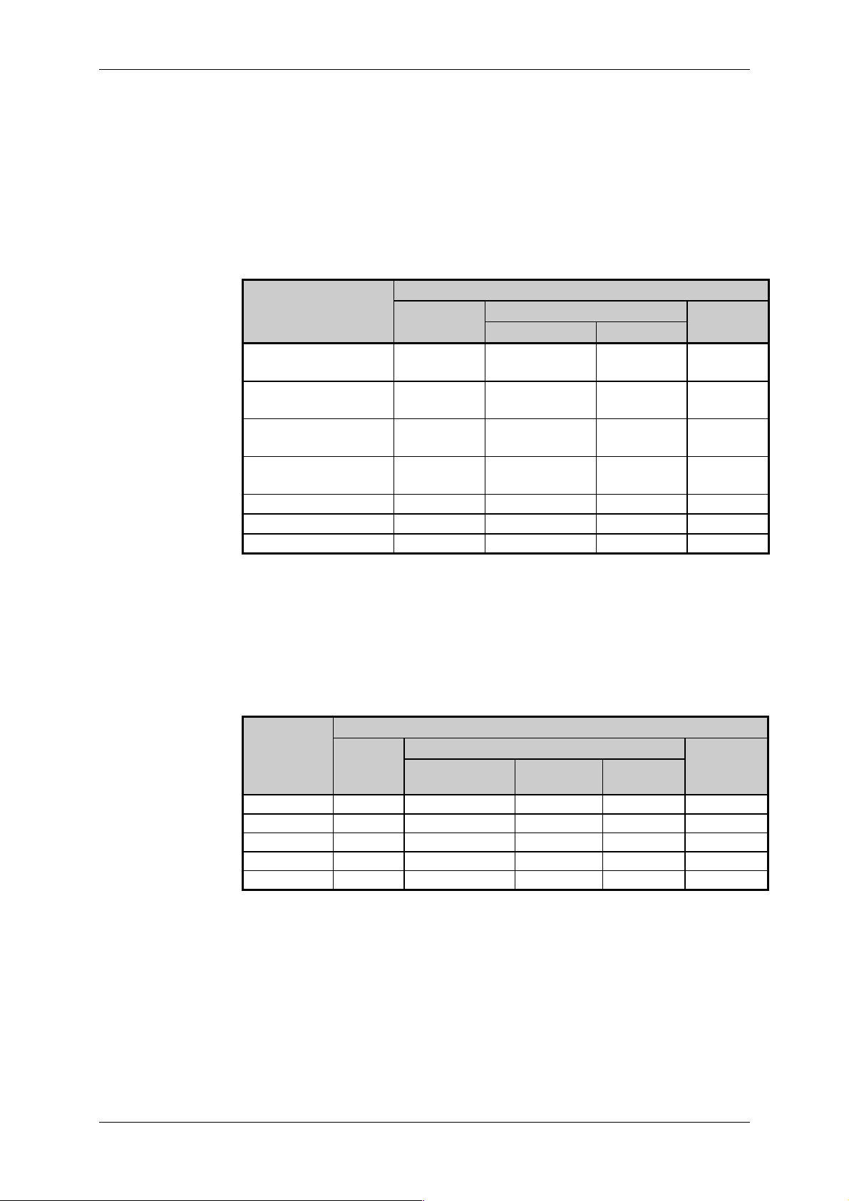
Formats of input data
Value of the input v ariabl e is passed in one of three f ormats. Format of
input data is selected in a program.
Format FS
In the FS f orm at (Ful l S cale), v alue 0 of input dat a corresponds with the
lower limit of the measurement range, the maximum value of input data
65535 corresponds with the upper limit of the measurement range. Exceeding of the range of the conv erter is not signalled. Conversion to technical uni ts is perf ormed on t he user program lev el . The F S f orm at provi des
the highest possible resol ution.
Technical units
In the Technical units format, converted value of the input variable is
passed in C, , A or mV. Exceeding of the range is signalled by v alue
TXV 138 08.02 26
Format PID
Format of input
data of resist anc e
temperature
scanners
Technical equipment of TC600 PLC
$7FFF, underflow of the range i s signalled by v alue $-7FFF ($8001). Detailed dat a on signalli ng of ov erf low and underflow of the r ange for indiv idual types of inputs - see notes to table 5.1.
In the PID f or m at, v al ue of t he i nput vari able i s passed, c onv er ted to t he
format compatible with PID instructions of Tecomat programmable logic
controllers. The val ue can be interpreted as percentage expression of the
full measurement range. Ex ceeding of the range is signalled by the v alue
$7FFF. Detailed data on signalling exceeding of the range for i ndiv idual i nput types - see notes to tabl e 5.1.
Tab. 5.1a. Format of input data of TC634 r esi stanc e temperatur e scanners
Data format
Scanner type/ FS Technical units PID
measurement rang e
Pt100, W 100 = 1. 385
-200 to +850 C
Pt100, W 100 = 1. 391
-200 to +850 C
Ni1000, W 100 = 1.617
-60 to +200 C
Ni1000, W 100 = 1.500
-60 to +200 C
0 to 630
0 to 2520
tenths of C
1)2)
tenths of
0 to 65535 -2000 to +8500
0 to 65535 -2000 to +8500
0 to 65535 -600 to +2000
0 to 65535 -600 to +2000
0 to 65535 0 to 6300 0 to 10000
0 to 65535 0 to 25200 0 to 10000
3
3
1)
At conv ersion to the f ormat of °C tenths, correction of non-linearity of
"#$%
(idt EN 60751: 1995) .
2)
For the marked format, value $7FFF signals interruption of the scanner,
value $-7FFF ($8001) signals short circuit of the scanner.
3)
For the m arked form at, ex ceeding of the upper lim it of the range is signalled by value $7FFF.
Tab. 5.1b. Format of input data of TC634 c ur r ent and voltage input s
Data format
Measurement
range
0 to +20 mA 0 to 65535 0 to 20000
+4 to +20 mA 0 to 65535 4000 to 20000
0 to +10 V 0 t o 65535 0 to 10000
0 to +2 V 0 to 65535 0 to 20000 4)0 to 10000
1)
For the marked format, exceeding of the range at current higher than
22 mA is signalled.
2)
For the marked format, exceeding of the range at current higher than
FS Technical units PID
A
1)
2)
mV tenths of
mV
3)
0 to 10000
0 to 10000
0 to 10000
22 mA is signalled, and underflow of the range at current lower than
3.5 mA.
3)
For the marked format, exceeding of the range at voltage higher than
10.1 V is signalled.
4)
For the marked format, exceeding of the range at voltage higher than
2.1 V is signalled.
1)
2)
3)
4)
27 TXV 138 08.02
Tecomat TC600
Resolution of input
data
Resolution of input
data of resist anc e
temperature sc anner s
Resolution of input
data of current and
voltage inputs
Resolution means the smallest detectable change of the input variable
expressed in techni cal units. It represents the val ue of the l east signif icant
bit of input data (LSB).
Tab. 5.2a. Resolution of input data of TC634 resistance tem perature scan-
ners
Data format
Scanner type FS Technical units PID
Pt100, W 100 = 1. 385
Pt100, W 100 = 1. 391
Ni1000, W 100 = 1.617
Ni1000, W 100 = 1.500
0 to 630
0 to 2520
tenths of C
0.016021 C/ LSB 0.1 C/ LSB
0.016021 C/ LSB 0.1 C/ LSB
0.0039673 C/ LSB 0.1 C/ LSB
0.0039673 C/ LSB 0.1 C/ LSB
9.6131 m/ LSB 0.1/ LSB
38.452 m/ LSB 0.1/ LSB
tenths of
0.01 %/ LSB
0.01 %/ LSB
Tab. 5.2b Resolut ion of input data of TC634 current and vol tage inputs
Data format
Measurement
range
0 to +20 mA
+4 to +20 mA
0 to +10 V 0. 15259 mV 1 mV /LSB 0. 01 % /LSB
0 to +2 V 0. 030518
FS Technical units PID
A
0.30518 A1 A /LSB
0.24414 A1 A /LSB
mV
mV tenths of mV
0.1 mV /LSB 0.01 % / LSB
0.01 % /LSB
0.01 % /LSB
Accuracy of
measurement of
inputs for resis tance
temperature
scanners
Accuracy of
measurement of
current and voltage
inputs
Tab. 5.3a. Accuracy of measurement of inputs for TC634 resistance tem-
perature scanners
Scanner type Maximu m error
(25 °C)
Pt100, W 100 = 1. 385
Pt100, W 100 = 1. 391
Ni1000, W 100 = 1.617
Ni1000, W 100 = 1.500
0 to 630
0 to 2520
0.5 C
0.5 C
0.4C
0.4C
2
8
Temperature dr i f t
(0 to 50 °C)
0.011 C/ C
0.011 C/ C
0.009 C/ C
0.009 C/ C
40 m/ C
70 m/ C
Tab. 5.3b Accuracy of measurement of TC634 current and volt age inputs
Measurement range
0 to +20 mA
+4 to +20 mA
0 to +10 V
0 to +2 V
Maximum error
(25 °C)
400 A
400 A
200 mV
40 mV
Temperature dr i f t
( 0 to 50 °C)
8
A / C
8
A / C
4 mV / C
800 V / C
TXV 138 08.02 28

Properties of interrupt
inputs
Technical equipment of TC600 PLC
5.2 Special Functions
Basic BM functions of TC603 to TC607 can be extended by special
functions.
Special functi ons use standard-f it ted i nput s, or possibly PLC out puts, but
their attendance requires more complex shell al gorithms or complementation of the basic technical equipment of the input and output unit. These
servi ng algorithms are real ized by the system program , thus servi cing performed by the user program r emains sim ple.
Special f unct ions are compl em ented t o select ed BM t ypes per order (see
Article 2.5). Always one special func tion may be c omplemented only.
5.2.1 Interrupt Inputs
Interrupt inputs allow for fast access to user programs for servicing of
time critical operational states of the controlled object, and processing of
fast changes of input signals processing of which by standard binar y inputs
is not possible.
Change of state of binary inputs DI0, DI1, DI2 or DI3 is done by the i nterruption process P42 which m ay be used to service the stat e. At the same
time, flags are set determining source of the interrupt in the STAT state
word. Activ ation of the interruption process from individual inputs can be
controlled by setting the relevant bits of the CONT control word. In ev ery
input, it is possible to individual ly set the signal edge that activates the int er rupt.
Interrupt inputs do not disturb neither limi t basic func tions of inputs DI0 to
DI3 described under i tem 5.1. 1.
Parameters of
interrupt inputs
Properties of the type
3 counter
TC601, TC602 TC603 to T C607
Number of interrupt inputs - 4
Voltage for log. 0
(opening of the circuit)
Voltage for log. 1
(closing of the cir c uit)
Delay f r om log. 0 to log.1
Delay f r om log. 1 to log.0
Width of the input pul se
Interrupt per iod see item 10.5.8
Response time of the PLC see item 10.5.8
For other parameters see item 5.1.1.
5.2.2 Counter of Type 3
Counter of type 3 is a unidirectional 16 bit counter of external ev ents
equipped with pre-selection, counting (CLK) and resetting input (RESET).
The counter can operat e as a freely running counter (in t he range of 0 to
65535) or self- filling counter (in the range of 0 to pre-selection).
The binary input DI0 is used as the CLK input, binary input DI1 i s used as
the RESET input. When the RESET input state corresponds with log. 1
(closed input), the counter counts ascending edges of signals on the CLK
input. W hen the RESET input state corresponds with log. 0 (open input ), t he
counter is reset permanently. Overf low of the count er range or reaching of
the pre-selection will evoke interruption process P44 of the user program. At
the same ti me, setti ng of rel evant bits in the ST AT state word of the counter. Reset and blocking of t he count er can be al so done f rom withi n t he user
program by sett ing the relevant bit in t he CONT control word of the count er .
Use of binary i nputs as the counter inputs does not di sturb neither lim it
their basic function described under item 5.1. 1.
max. 14V-, 13.5V~
min. 18.5 V-, 17.5 V~
max. 30 V-, 30 V~
max. 5 s
max. 5 s
min. 30 s
29 TXV 138 08.02

Tecomat TC600
Parameters of the
type 3 counter
Incremental encoder
admeasurement
properties
TC601, TC602 TC603 to TC607
Number of counters - 1
Nominal voltage 24 VVoltage for log. 0
(opening of the circuit)
Voltage for log. 1
(closing of the cir c uit)
Range 16 bits (0 to 65535)
Delay f r om log. 0 to log.1
Delay f r om log. 1 to log.0
Input f r equenc y / resolution
capability
Interrupt per iod min. 10 ms
Pulse width
For other parameters see item 5.1.1.
5.2.3 Admeasurement of P osition by the Incremental Enco der
The functi on of admeasurement by the increm ental encoder i s designed
for processing of incremental encoder signals with outputs with an open
collector.
In the admeasurement, it is operated with signed ar it hm eti cs i n the range
of long (4 byt es) between li m it s -2147483648 (8000 0000h) t o +2147483647
(7FFF FFFFh) with 0 in between. It allows for adm easuring with r esolution
of the m ovem ent di rect i on, sett ing of one pre-select i on for every m ovem ent
directi on, resoluti on of positi on towards pre-selections and searching out of
the refer ence point. Af ter reachi ng of a pre-selecti on, ov erfl ow or under fl ow
of the range, relev ant bits are set i n the STAT state word and the interruption process P44 is evoked. Control of admeasurement is performed
through the CONT state word.
To connect the enc oder, binar y inputs DI0 ( direct output of trac e 1 of incremental encoder), DI1 (direct output of trace 2 of increm ental encoder),
and DI3 (direct output of the zero pulse of incremental encoder ) ar e used.
Use of binary i nputs f or connecti on of increm ental encoder does not disturb neither lim it thei r basi c function described under item 5.1. 1.
max. 14 V-
min. 18.5 V-
max. 30 V-
max. 5 s
max. 5 s
max. 30 kHz / 3 pulses
(10 kHz / 1 pulse)
min. 30 s
Circuits paramet er s
for incremental
encoder connection
TXV 138 08.02 30
Number of encoders - 1
Nominal voltage 24 VGalvanic separation from
other elect r ic circ uits
Voltage for log. 0
(opening of the circuit)
Voltage for log. 1
(closing of the cir c uit)
Current f or log. 1 typ. 10 m A
Delay f r om log. 0 to log.1
Delay f r om log. 1 to log.0
Input f r equenc y
/ resoluti on c apability
Pulse width
Interrupt per iod min. 10 ms
Range of the admeasured
variable
For other parameters see item 5.1.1.
TC601, TC602 TC603 to TC607
yes
max. 14 V-
min. 18.5 V-
max. 30 V-
max. 5 s
max. 5 s
max. 30 kHz / 12 pulses
(2.5 kHz / 1 pulse)
min. 30 s
32 bits
(- 2 147 483 648 to+ 2 147 483 647)
 Loading...